

Page 1
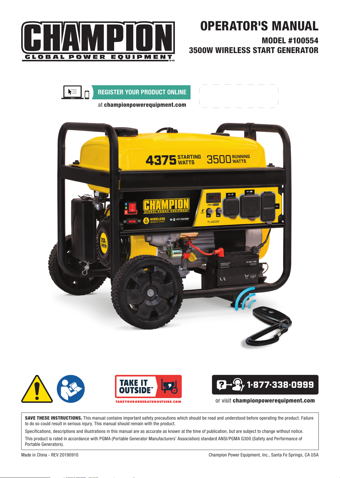
OPERATOR'S MANUAL
MODEL #100554
3500W WIRELESS START GENERATOR
Made in China - REV 20190910 Champion Power Equipment, Inc., Santa Fe Springs, CA USA
or visit championpowerequipment.com
SAVE THESE INSTRUCTIONS. This manual contains important safety precautions which should be read and understood before operating the product. Failure
to do so could result in serious injury. This manual should remain with the product.
Specifications, descriptions and illustrations in this manual are as accurate as known at the time of publication, but are subject to change without notice.
This product is rated in accordance with PGMA (Portable Generator Manufacturers’ Association) standard ANSI/PGMA G300 (Safet y and Performance of
Portable Generators).
REGISTER YOUR PRODUCT ONLINE
at championpowerequipment.com
Page 2

100554 - 3500W WIRELES S START GENERATOR
TABLE OF CONTENTS
TABLE OF CONTENTS
Introduction ................................................ 3
Safety Definitions
Important Safety Instructions
Fuel Safety ...................................................... 6
Safety Labels .................................................... 7
Safety Symbols .................................................. 8
Operation Symbols .............................................. 9
Quick Start Label Symbols.....................................10
Controls and Features ...............................11
Generator .......................................................11
Control Panel ................................................... 12
Intelligauge .....................................................13
Wireless Remote Control .......................................14
FCC Statement for Remote Control Device....................14
Parts Included ..................................................15
Too ls N eeded ...................................................15
Assembly ...................................................16
Unpacking ......................................................16
Remove Shipping Support Brackets ...........................16
Install the Wheel Kit ............................................16
Connect the Battery ............................................17
Add Engine Oil ..................................................17
Add Fuel ........................................................18
Grounding ......................................................19
Operation ...................................................19
Generator Location .............................................19
Surge Protection ...............................................20
Starting the Engine .............................................20
Battery ..........................................................22
Connecting Electrical Loads ...................................22
Do Not Overload Generator ....................................23
Stopping the Engine ............................................23
Operation at High Altitude .....................................24
....................................... 3
.................... 4
Maintenance ............................................. 25
Cleaning the Generator ........................................25
Changing the Engine Oil .......................................25
Cleaning and Adjusting the Spark Plug ........................25
Cleaning the Air Filter ..........................................26
Cleaning the Spark Arrestor ...................................26
Adjusting the Governor .........................................26
Generator Battery ..............................................26
Remote Control Battery ........................................27
Maintenance Schedule .........................................27
Storage ..................................................... 27
Short Term Storage (up to 30 days) ...........................27
Mid Term Storage (30 days – 1 year) .........................27
Long Term Storage (over 1 year) ..............................28
Removing from Storage ........................................28
Specifications ........................................... 29
Generator Specifications .......................................29
Engine Specifications ..........................................29
Oil Specifications ...............................................29
Fuel Specifications .............................................29
Battery Specifications..........................................29
Temperature Specific ati ons ....................................29
Parts Diagram ..................................................30
Parts List .......................................................31
Engine Parts Diagram ..........................................33
Engine Parts List ...............................................34
Wiring Diagram .................................................36
Troubleshooting ........................................ 37
2
Page 3

100554 - 3500W WIRELESS START GENERATOR
INTRODUCTION
INTRODUCTION
Congratulations on your purchase of a Champion Power
Equipment (CPE) product. CPE designs, builds, and supports
all of our products to strict specifications and guidelines. With
proper product knowledge, safe use, and regular maintenance,
this product should bring years of satisfying service.
Every effort has been made to ensure the accuracy and
completeness of the information in this manual at the time
of publication, and we reserve the right to change, alter and/
or improve the product and this document at any time without
prior notice.
CPE highly values how our products are designed,
manufactured, operated, and serviced as well as providing
safety to the operator and those around the generator.
Therefore, it is IMPORTANT to review this product manual
and other product materials thoroughly and be fully aware
and knowledgeable of the assembly, operation, dangers
and maintenance of the product before use. Fully familiarize
yourself, and make sure others who plan on operating the
product fully familiarize themselves too, with the proper safety
and operation procedures before each use. Please always
exercise common sense and always err on the side of caution
when operating the product to ensure no accident, property
damage, or injury occurs. We want you to continue to use and
be satisfied with your CPE product for years to come.
When contacting CPE about parts and/or service, you will
need to supply the complete model and serial numbers of your
product. Transcribe the information found on your product’s
nameplate label to the table below
SAFETY DEFINITIONS
The purpose of safety symbols is to attract your attention to
possible dangers. The safety symbols, and their explanations,
deserve your careful attention and understanding. The safety
warnings do not by themselves eliminate any danger. The
instructions or warnings they give are not substitutes for proper
accident prevention measures.
! DANGER
DANGER indicates a hazardous situation which,if not
avoided, will result in death or serious injury.
! WARNING
WARNING indicates a hazardous situation which, if not
avoided, could result in death or serious injury.
! CAUTION
CAUTION indicates a hazardous situation which, if not
avoided, could result in minor or moderate injury.
"
NOTICE
NOTICE indicates information considered important, but
not hazard-related (e.g., messages relating to property
damage).
CPE TECHNICAL SUPPORT TEAM
1-8 77-338-0 999
MODEL NUMBER
100 55 4
SERIAL NUMBER
DATE OF PURCHASE
PURCHASE LOCATION
3
Page 4

100554 - 3500W WIRELESS START GENERATOR
IMPORTANT SAFETY INSTRUCTIONS
IMPORTANT SAFETY INSTRUCTIONS
! WARNING
Cancer and Reproductive Harm – www.P65Warnings.ca.gov
! DANGER
Generator exhaust contains carbon monoxide, a colorless,
odorless, poisonous gas. Breathing carbon monoxide will
cause nausea, dizziness, fainting or death. If you start to
feel dizzy or weak, get to fresh air immediately.
OPERATE GENERATOR OUTDOORS ONLY IN A WELL
VENTILATED AREA AND POINT EXHAUST AWAY.
DO NOT operate the generator inside any building, including
garages, basements, crawlspaces and sheds, enclosure or
compartment, including the generator compartment of a
recreational vehicle.
DO NOT allow exhaust fumes to enter a confined area
through windows, doors, vents or other openings.
! DANGER
Using a generator indoors CAN KILL YOU IN MINUTES.
Generator exhaust contains carbon monoxide. This is a
poison you cannot see or smell.
NEVER use inside a home or garage, EVEN IF doors and
windows are open.
ONLY use OUTSIDE and far away from windows, doors,
and vents.
! DANGER
Operate equipment with guards in place.
Rotating parts can entangle hands, feet, hair, clothing and/
or accessories. Traumatic amputation or severe laceration
can result.
Keep hands and feet away from rotating parts.
Tie up long hair and remove jewelry.
DO NOT wear loose-fitting clothing, dangling drawstrings or
items that could become caught.
! DANGER
Generator produces powerful voltage.
DO NOT touch bare wires or receptacles.
DO NOT use electrical cords that are worn, damaged or
frayed. Use only Champion electrical cords for proper
application.
DO NOT operate generator in wet weather.
DO NOT allow children or unqualified persons to operate or
service the generator.
Use a ground fault circuit interrupter (GFCI) in damp areas
and areas containing conductive material such as metal
decking.
Connection to your home’s electrical system requires a
listed 30A transfer switch installed by a licensed electrician
and approved by the local authority having jurisdiction. The
connection must isolate the generator from the utility power
and must comply with all applicable laws and electrical
codes.
Install battery-operated carbon monoxide alarms or plug-in
carbon monoxide alarms with battery back-up according to
the manufacturer’s instructions.
! WARNING
Although the generator contains a spark arrester, maintain
a minimum distance of 5 ft. (1.5m) from dry vegetation to
prevent fires.
! WARNING
Do not use generator for medical and life support uses.
In case of emergency, call 911 immediately.
NEVER use this product to power life support devices or life
support appliances.
NEVER use this product to power medical devices or
medical appliances.
Inform your electricity provider immediately if you or anyone
in your household depends on electrical equipment to live.
Inform your electrical provider immediately if a loss of power
would cause you or anyone in your household to experience
a medical emergency.
4
Page 5

100554 - 3500W WIRELESS START GENERATOR
IMPORTANT SAFETY INSTRUCTIONS
! WARNING
Spark from removed spark plug wire can result in fire or
electrical shock.
When servicing the generator:
Disconnect the spark plug wire and place it where it cannot
contact the plug or any other metal object.
DO NOT check for spark with the plug removed.
Use only approved spark plug testers.
! WARNING
Running engines produce heat. Severe burns can occur on
contact. Combustible material can catch fire on contact.
DO NOT touch hot surfaces.
Avoid contact with hot exhaust gases.
Allow equipment to cool before touching.
Maintain at least 3 ft. (91.4 cm) of clearance on all sides to
ensure adequate cooling.
Maintain at least 5 ft. (1.5 m) of clearance from combustible
materials.
! CAUTION
Improper treatment or use of the generator can damage it,
shorten its life or void the warranty.
Use the generator only for intended uses.
Operate only on level surfaces.
DO NOT expose generator to excessive moisture, dust,
or dirt.
DO NOT allow any material to block the cooling slots.
If connected devices overheat, turn them off and disconnect
them from the generator.
DO NOT use the generator if:
– Electrical output is lost
– Equipment sparks, smokes or emits flames
– Equipment vibrates excessively
! WARNING
This product contains a button battery. If swallowed, it could
cause severe injury or death in just 2 hours. Seek medical
attention immediately.
! WARNING
Rapid retraction of the starter cord will pull hand and arm
towards the engine faster than you can let go. Unintentional
startup can result in entanglement, traumatic amputation or
laceration. Broken bones, fractures, bruises or sprains could
result.
When starting engine, pull the starter cord slowly until
resistance is felt and then pull rapidly to avoid kickback.
DO NOT start or stop the engine with electrical devices
plugged in and turned on.
! CAUTION
Exceeding the generator’s running capacity can damage the
generator and/or electrical devices connected to it.
DO NOT overload the generator.
DO NOT tamper with the governed speed.
DO NOT modify the generator in any way.
5
Page 6

100554 - 3500W WIRELESS START GENERATOR
IMPORTANT SAFETY INSTRUCTIONS
Fuel Safety
! DANGER
GASOLINE AND GASOLINE VAPORS ARE HIGHLY
FLAMMABLE AND EXPLOSIVE.
Fire or explosion can cause severe burns or death.
Gasoline and gasoline vapors:
– Gasoline is highly flammable and explosive.
– Gasoline can cause a fire or explosion if ignited.
– Gasoline is a liquid fuel but it’s vapors can ignite.
– Gasoline is a skin irritant and needs to be cleaned up
immediately if spilled on skin or clothes.
– Gasoline has a distinctive odor, this will help detect potential
leaks quickly.
– In any petroleum gas fire, flames should not be extinguished
unless by doing so the fuel supply valve can be turned OFF.
This is because if a fire is extinguished and a supply of
fuel is not turned OFF, then an explosion hazard could be
created.
When operating the generator:
DO NOT move or tip the generator during operation.
DO NOT tip the generator or allow fuel or oil to spill.
When transporting or servicing the generator:
Make certain that the fuel valve is in the OFF position and the
gasoline tank is empty.
Disconnect the spark plug wire.
When storing the generator:
Store away from sparks, open flames, pilot lights, heat and
other sources of ignition.
Do not store generator or gasoline near furnaces, water heaters,
or any other appliances that produce heat or have automatic
ignitions.
! WARNING
Never use a gasoline container, gasoline tank, or any other
fuel item that is broken, cut, torn or damaged.
– Gasoline expands or contracts with ambient temperatures.
Never fill the gasoline tank to full capacity, as gasoline
needs room to expand if temperatures rise.
When adding or removing gasoline:
DO NOT light or smoke cigarettes.
Turn the generator off and let it cool for at least two minutes
before removing the gasoline cap. Loosen the cap slowly to
relieve pressure in the tank.
Only fill or drain gasoline outdoors in a well-ventilated area.
DO NOT pump gasoline directly into the generator at the gas
station. Use an approved container to transfer the fuel to the
generator.
DO NOT overfill the gasoline tank.
Always keep gasoline away from sparks, open flames, pilot
lights, heat and other sources of ignition.
When starting the generator:
DO NOT attempt to start a damaged generator.
Make certain that the gasoline cap, air filter, spark plug, fuel
lines and exhaust system are properly in place.
Allow spilled gasoline to evaporate fully before attempting to
start the engine.
Make certain that the generator is resting firmly on level
ground.
6
Page 7
100554 - 3500W WIRELESS START GENERATOR
IMPORTANT SAFETY INSTRUCTIONS
7
Top
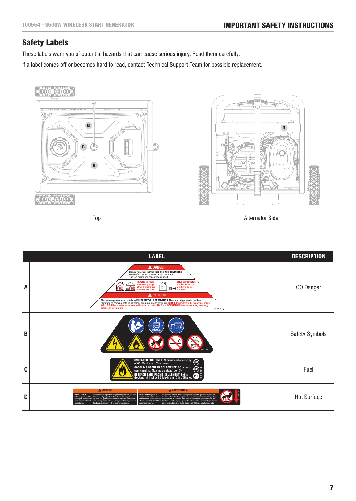
Safety Labels
These labels warn you of potential hazards that can cause serious injury. Read them carefully.
If a label comes off or becomes hard to read, contact Technical Support Team for possible replacement.
Alternator Side
LABEL DESCRIPTION
A
1448-L-SF -A
El uso de un generador en interiores PUEDE MATARLO EN MINUTOS. El escape del generador contiene
monóxido de carbono. Éste es un veneno que no se puede ver ni oler. NUNCA lo use dentro del hogar ni el garaje,
INCLUSO SI las puertas y ventana s están abiertas. Úselo SÓLO a la INTEMPERIE lejos de ventanas, puerta s, y
orificios de ventilación.
ONLY use OUTSIDE
and far away from
windows, doors,
and vents.
NEVER use inside
a home or garage,
EVEN IF doors and
windows are open.
Using a generator indoors CAN KILL YOU IN MINUTES.
Generator exhaust contains carbon monoxide.
This is a poison you cannot see or smell.
! DANGER
! PELIGRO
CO Danger
B
1161-L-SF-A
Safety Symbols
C
UNLEA DED FUEL ONLY. Minimum octa ne rating
of 85. Max imum 10% ethanol.
GASOLI NA REGULAR SO LAMENTE. 85 o ctanos
como mínimo. M áximo de etanol de 10 %.
ESSENC E SANS PLOMB SEULE MENT. Indice
d’octane minimal de 85. Maximum 10 % d'éthanol.
1032-L- OP-A
Fuel
D
! WARNING
DO NOT TOUCH!
Exhaust gases, muffler
and engine components
are extremely HOT and
cause burns.
Operation of this equipment may create sparks that can start
fires around dry vegetation. A spark arrestor may be
required. The operator should contact local fire agencies for
laws and regulations relating to fire prevention requirements.
If installed, clean every 100 hours or every season.
! ADVERTENCIA
¡NO TOCAR! Los gas es de
escape, el silenciador y los
compnonentes del motor están
extremadamente CALIENTES y
causan quemaduras.
La operación de este equipo puede producir chispas que pueden provocar
incendios alrededor de la vegetación seca. Un supresor de chispas puede que
sea necesario. El operador debe comunicarse con las agencias locales de
bomberos para las leyes y reglamentos relativos a los requisitos de prevención
de incendios. Si está instalado, limpie cada 100 horas o cada temporada.
1291-L-SF-A
Hot Surface
B
A
C
D
Page 8

100554 - 3500W WIRELESS START GENERATOR
IMPORTANT SAFETY INSTRUCTIONS
Safety Symbols
Some of the following symbols may be used on this product. Please study them and learn their meaning. Proper interpretation of
these symbols will allow you to more safely operate the product.
SYMBOL MEANING
Read Operator’s Manual. To reduce the risk of injury, user must read and understand operator’s
manual before using this product.
Clearance. Keep all objects at least 5 feet from generator. Heat from the muffler and exhaust gas
can ignite combustible objects.
Ground. Consult with local electrician to determine grounding requirements before operation.
Electric Shock. Failure to use in dry conditions and to observe safe practices can result in electric
shock. Improper connections to a building can allow current to backfeed into utility lines, creating an
electrocution hazard. A transfer switch must be used when connecting to a building.
Fire/Explosion. Fuel and its vapors are extremely flammable and explosive. Fire or explosion
can cause severe burns or death. Keep generator at least 5 ft (1.5m) from all objects to prevent
combustion.
Hot Surface. To reduce the risk of injury or damage, avoid contact with any hot surface.
Open Flame Alert. Fuel and its vapors are extremely flammable and explosive. Keep fuel away from
smoking, open flames, sparks, pilot lights, heat, and other ignition sources.
Wet Conditions Alert. Do not expose to rain or use in damp locations.
8
Page 9
100554 - 3500W WIRELESS START GENERATOR
IMPORTANT SAFETY INSTRUCTIONS
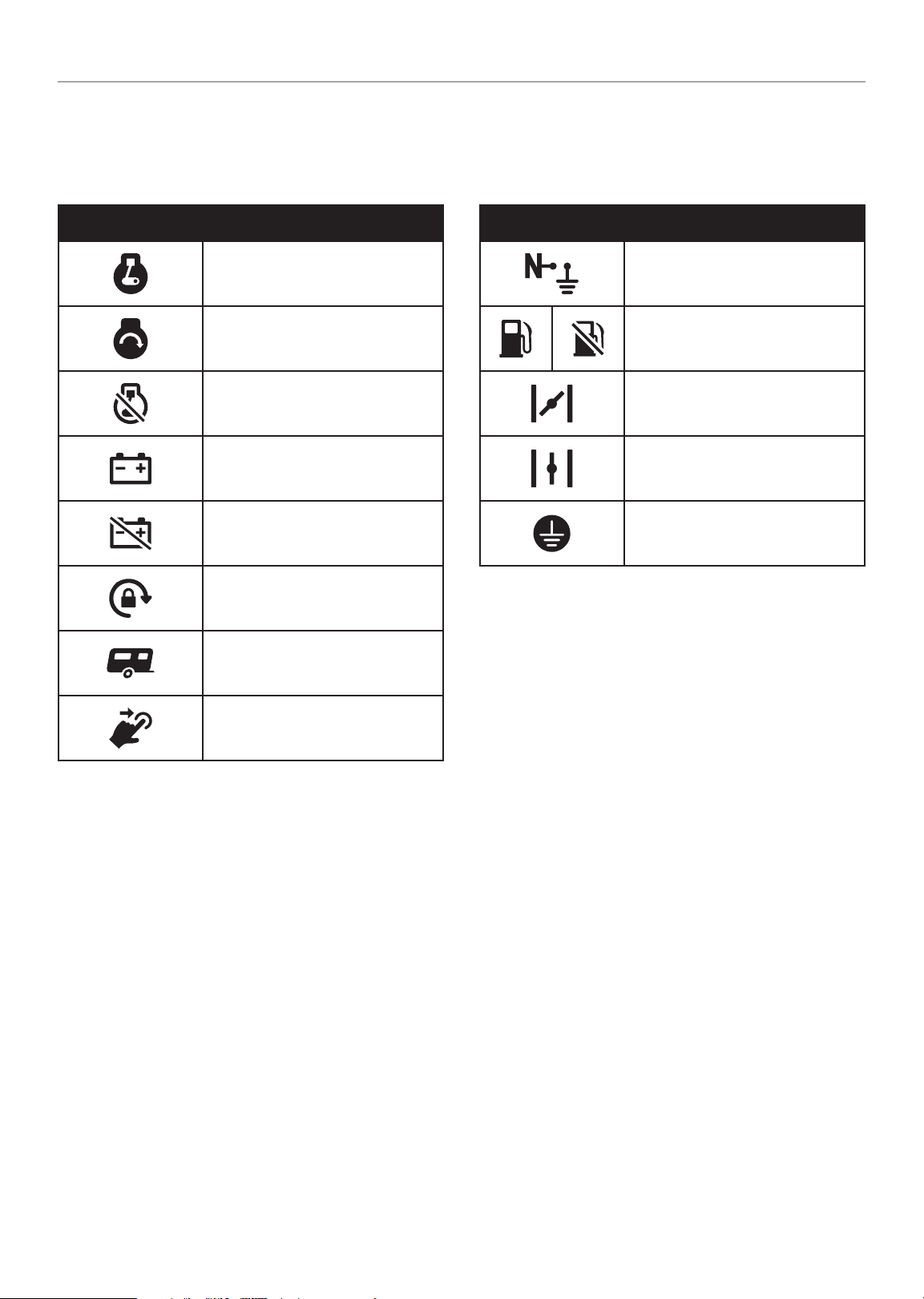
Operation Symbols
Some of the following symbols may be used on this product. Please study them and learn their meaning. Proper interpretation of
these symbols will allow you to more safely operate the product.
SYMBOL MEANING
ON
START
STOP or OFF
Battery ON
Battery OFF
Locking Receptacle
RV Ready Receptacle
SYMBOL MEANING
Neutral Floating. Neutral circuit IS
NOT electrically connected to the frame/
ground of the generator.
Fuel/Gasoline Valve ON/OFF
Choke
Run
Ground Terminal
Circuit Breaker Reset: Push
9
Page 10
100554 - 3500W WIRELESS START GENERATOR
1498-L -OP-A
1 1 2 32 3 4 5
10W-30
!
76 8
!
IMPORTANT SAFETY INSTRUCTIONS
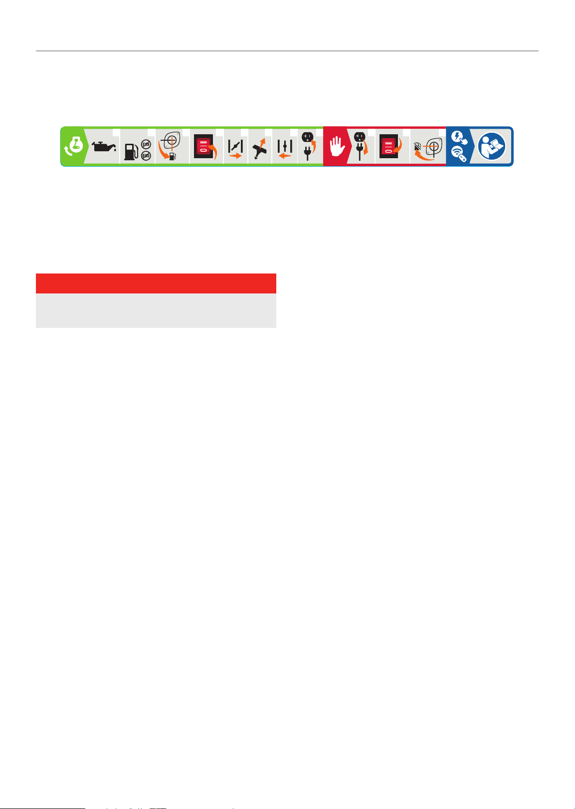
Quick Start Label Symbols
Some of the following symbols may be used on this product. Please study them and learn their meaning. Proper interpretation of
these symbols will allow you to more safely operate the product.
Starting the Engine
! DANGER
Move generator outside and far away from windows,
doors and intake ventilation covers.
1. Check oil level.
Recommended oil is 10W-30.
2. Check gasoline level.
When adding gasoline, use a minimum octane rating of 85
and an ethanol content of 10% or less by volume.
3. Turn the fuel valve t o “ON” position.
4. Press ignition switch to the “ON” position.
5. Move choke lever to “CHOKE” position.
6. Pull the recoil starter.
7. Move the choke lever to “RUN” position.
8. Plug in desired device.
Stopping the Engine
1. Tur n off an d unplug all c onnected elect ric al loads .
2. Press the ignition switch to the “OFF” position.
3. Turn the fuel valve t o t he “OFF” position.
Wireless and Electric Start
See page 20 in “Operation” section.
10
Page 11
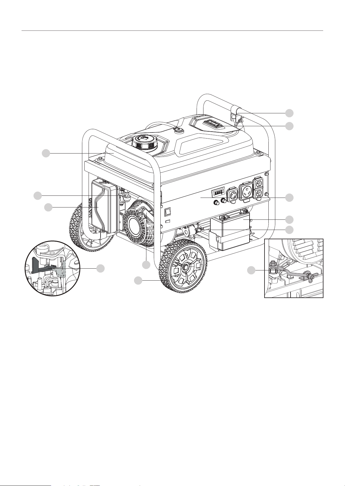
100554 - 3500W WIRELESS START GENERATOR
CONTROLS AND FEATURES
CONTROLS AND FEATURES
Read this operator’s manual before operating your generator. Familiarize yourself with the location and function of the controls and
features. Save this manual for future reference.
Generator
10
9
1
2
3
11
4
5
1. Gasoline Tank – 4.7 gal. (17.8 L)
2. Fuel Valve – Used to turn fuel supply on and off to engine.
3. Air Filter – Protects the engine by filtering dust and debris
from the intake air
4. Recoil Starter – Used to manually start the engine
5. Never Flat Wheels – 8 in. (20.3 cm)
6. Oil Fill Cap/Dipstick – Used to check and fill oil level.
7. Battery – Provides 12V DC power the starting system.
8
7
6
12
8. Control Panel – See “Control Panel” section.
9. Fuel Gauge – Indicates the amount of gasoline in the fuel
tank.
10. Folding Handle – Used to move unit by lifting and rolling
on wheels. Do not use to lift or carry the unit.
11. Choke – Used to start the engine.
12. Ground Terminal – Consult an electrician for local
grounding regulations.
11
Page 12
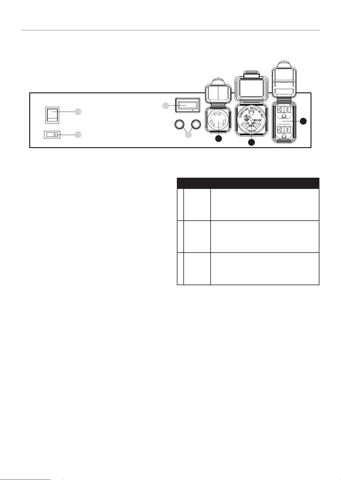
100554 - 3500W WIRELESS START GENERATOR
Control Panel
1
CONTROLS AND FEATURES
3
C
2
1. Ignition Switch – Used to START or STOP the generator.
2. Battery Switch – Enables/disables starting electrically.
3. Intelligauge – Four mode digital meter for displaying
voltage, frequency (hertz), run time, and total run time.
4. Circuit Breakers (Push Reset) – Protects the generator
against electrical overloads.
4
A
W
B
t
C
A
A
RECEPTACLES
120V AC, 30A Locking ( NEMA L5-30R)
May be used to supply electrical power for
operation of 120 Volt AC, 30 Amp, single
phase, 60 Hz electrical loads.
120V AC, 30A RV (NEMA TT-30 R)
May be used to supply electrical power for
operation of 120 Volt AC, 30 Amp, single
phase, 60 Hz electrical loads.
(2×) 120V AC, 20A (NEMA 5-20R)
May be used to supply electrical power for
operation of 120 Volt AC, 20 Amp, single
phase, 60 Hz electrical loads.
B
12
Page 13
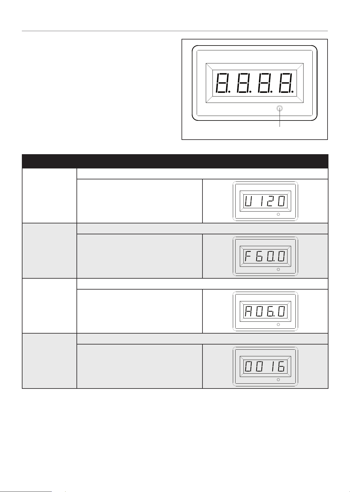
100554 - 3500W WIRELESS START GENERATOR
Intelligauge
Four mode digital meter for displaying voltage, frequency
(hertz), run time, and total run time.
The LCD displays each mode by pressing the button below the
display.
MODE DESCRIPTION
CONTROLS AND FEATURES
MODE BUTTON
Output voltage of the generator.
Voltage (V)
Frequency (F)
Run Time (R)
Tot al Run Time
Example: 120 volts
Output frequency in hertz.
Example: 60.0 hertz
Run time of the generator for the current session
Example: 6 hours
Tot al run time of the genera tor since first operat ion
Example: 16 hours
13
Page 14

100554 - 3500W WIRELESS START GENERATOR
CONTROLS AND FEATURES
Wireless Remote Control
This generator is equipped with a wireless remote control
system for starting and stopping. The system consists of (5)
main components:
1. Receiver Control Module (RCM)
2. Remote Control
3. Battery Switch
4. Ignition Switch
5. Auto-Choke
The Remote Control functions are enabled when:
1. The Ignition Switch is in the “ON” position, AND
2. The Battery Switch is in the “ON” position.
The Remote Control functions are disabled if either of the above
conditions is not met.
To start the generator wirelessly, press the “START” button
on the Remote Control one time. The engine will attempt to
start (6) times. The RCM controls the Auto-Choke during each
attempt to start. If the generator does not start, call Champion
Customer Care team for assistance at 1-877-338-0999.
To stop the generator wirelessly, press the “STOP” button on
the Remote Control one time.
Remote Control Power Consumption
While the Ignition Switch is in the “ON” position, the RCM is
active and waiting for a remote signal. This function requires
electrical current from the battery. If the Ignition Switch is left
in the “ON” position for extended periods (several weeks), the
battery can be completely drained.
Moving the Ignition Switch to the “OFF” position disables the
Remote functions, but the RCM still consumes approximately
2 mA from the battery.
When the push-button electric start or recoil start method is
used, the operator must be sure all electrical loads (appliances)
are turned OFF during startup and shutdown. Damage to the
generator or the attached appliances can be caused by starting
or stopping the generator while appliances are plugged in and
turned ON.
FCC Statement for Remote Control Device
1. This device complies with Part 15 of the FCC Rules.
Operation is subject to the following two conditions:
1a. This device may not cause harmful interference.
1b. This device must accept any interference received,
including interference that may cause undesired
operation.
2. Changes or modifications not expressly approved by the
party responsible for compliance could void the user’s
authority to operate the equipment.
! NOTICE
This equipment has been tested and found to comply with
the limits for a Class B digital device, pursuant to Part 15
of the FCC Rules. These limits are designed to provide
reasonable protection against harmful interference in a
residential installation. This equipment generates uses and
can radiate radio frequency energy and, if not installed
and used in accordance with the instructions, may cause
harmful interference to radio communications. However,
there is no guarantee that interference will not occur in a
particular installation. If this equipment does cause harmful
interference to radio or television reception, which can be
determined by turning the equipment off and on, the user is
encouraged to try to correct the interference by one or more
of the following measures:
To prevent battery drain, press the Battery Switch to the “OFF”
position. This disconnects power to the RCM so there is no
current draw on the battery.
Control Panel Load Management
When the generator initially starts wirelessly, no voltage is
supplied to the Control Panel for approximately 15 seconds. This
allows the engine to reach full speed before electrical loads are
applied to the generator.
When the generator is stopped wirelessly, the voltage to the
Control Panel is immediately turned off. Then the engine stops
approximately 5 seconds after the “STOP” button on the
Remote Control is pressed. Turning the Control Panel voltage
off before the engine shutdown protects connected appliances
from being damaged by non-60 Hz voltage while the generator
coasts to a stop.
The on/off voltage delay at startup and shut down only happen
when the Remote Control is used. There is no voltage delay
when the push-button electric start or recoil start method is
used.
– Reorient or relocate the receiving antenna.
– Increase the separation between the equipment and
receiver.
– Connect the equipment into an outlet on a circuit
different from that to which the receiver is connected.
Consult dealer or an experienced radio/TV technician for help.
14
Page 15
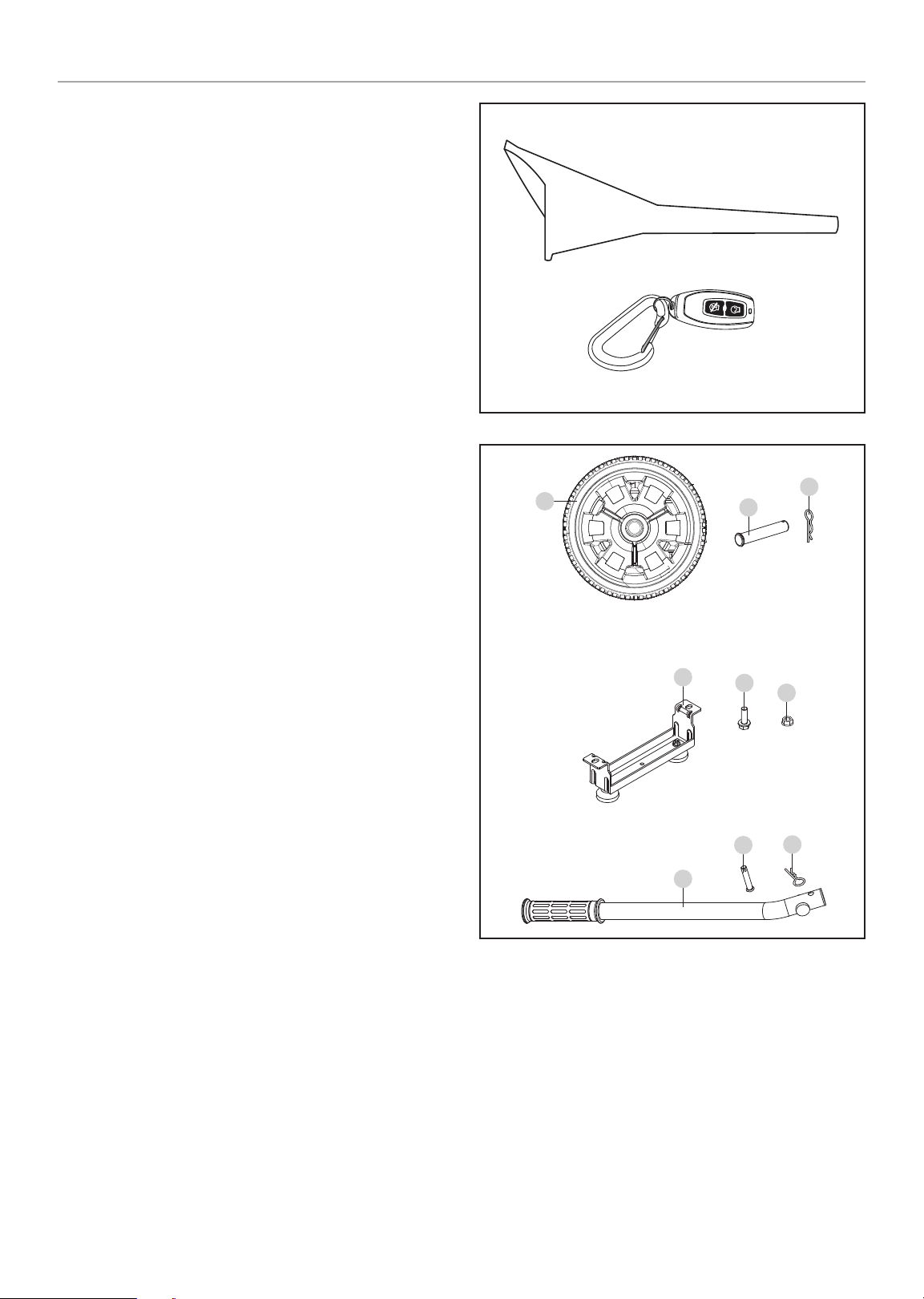
100554 - 3500W WIRELESS START GENERATOR
Parts Included
Accessories
Oil Funnel ..............................................................................1
Remote Key Fob ....................................................................1
Assembly Parts
Wheels
8 in. (20.3 cm) Never Flat Wheel (A) ..................................2
Roll Pin (B)........................................................................2
Large R-clip (C) ................................................................2
Engine Vibration Mounts
Support Leg with Vibration Mounts (D) .............................. 1
Flange Bolt (M8×16) (E) .................................................... 2
Flange Lock Nut (M8) (F) ..................................................2
Folding Handle
Handle (G) ........................................................................1
Short Pin (H) .....................................................................1
Small R-clip (I) .................................................................. 1
CONTROLS AND FEATURES
A
B
C
Tools Needed
– Wrench/Socket set (metric)
– Pliers
– Screwdriver
D
G
E
F
H
I
15
Page 16

100554 - 3500W WIRELESS START GENERATOR
ASSEMBLY
ASSEMBLY
Your generator requires some assembly. This unit ships from
our factory without oil. It must be properly serviced with fuel
and oil before operation.
If you have any questions regarding the assembly of your
generator, call our Technical Support Team at 1-877-338-0999.
Please have your serial number and model number available.
Unpacking
1. Set the shipping carton on a solid, flat surface.
2. Remove everything from the carton except the generator.
3. Carefully cut each corner of the box from top to bottom.
Fold each side flat on the ground to provide a surface area
to work with the generator.
Remove Shipping Support Brackets
To protect the generator during shipping, support brackets have
been installed between the engine and frame. These brackets
MUST BE REMOVED BEFORE adding oil or gasoline to the
generator.
Install the Wheel Kit
! CAUTION
The wheel kit is not intended for over-the-road use.
Install the Wheels
1. Slide the roll pin (B) through the wheel (A) from the outside.
2. Slide the roll pin through the mount point on the frame.
3. Secure with the R-clip (C).
4. Repeat to attach the second wheel.
"
NOTICE
DO NOT attempt to run generator without first removing the
shipping support brackets. Damage to the generator as a
result of not removing the brackets will void the warranty.
1. BEFORE filling the engine with oil or gasoline, tip the
generator onto it’s recoil end. Tip onto the flattened
cardboard box the generator came in or other protective
surface so as to not scratch the frame.
2. Remove the bolts from the orange support brackets. Bolts
and brackets can be discarded.
3. Tip the generator upright.
B
A
Install the Support Leg
1. Attach the support leg (D) to the generator frame with
flange bolts (E) and flange lock nuts (F).
2. Slowly tip the generator back down so that it rests on the
Wheels and support leg.
C
F
D
E
16
Page 17
100554 - 3500W WIRELESS START GENERATOR
ASSEMBLY
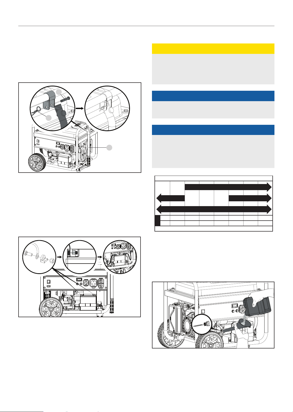
Install the Handle
1. Place the handle (G) inside the mounting channel on the
frame.
2. Secure the handle to the frame using an short pin (H).
3. Place an R-clip (I) on the end of the short pin and fasten
securely.
H
I
G
Add Engine Oil
! CAUTION
DO NOT attempt to crank or start the engine before it has
been properly filled with the recommended type and amount
of oil. Damage to the generator as a result of failing to follow
these instructions will void your warranty.
"
NOTICE
The generator rotor has a sealed, pre-lubricated ball bearing
that requires no additional lubrication for the life of the bearing.
"
NOTICE
The recommended oil type for typical use is 10W-30
automotive oil.
If running generator in extreme temperatures, refer to the
following chart for recommended oil type.
Recommended Engine Oil Type
Connect the Battery
1. Remove the protective cover from the red (+) lead on the
battery.
2. Attach the red (+) lead to the red (+) terminal on the
battery with the bolt and secure with the nut.
3. Repeat for the black (–) battery lead.
10W-30
10W-405W-30
5W-30 Synthetic
-20 0 20 40 60
°F
-28.9
°C -17.8 -6.7 4.4 15.6 26.7 37.8 48.9
Ambient temperature
80 100 120
1. Place the generator on a flat, level surface.
2. Remove oil fill cap/dipstick to add oil.
3. Using a funnel, add up to 18.6 fl. oz. / 0.6 qt. (0.6 L) of
oil (not included) and replace oil fill cap/dipstick. DO NOT
OVERFILL.
4. Check engine oil level at every use and add as needed.
17
Page 18
100554 - 3500W WIRELESS START GENERATOR
ASSEMBLY
"
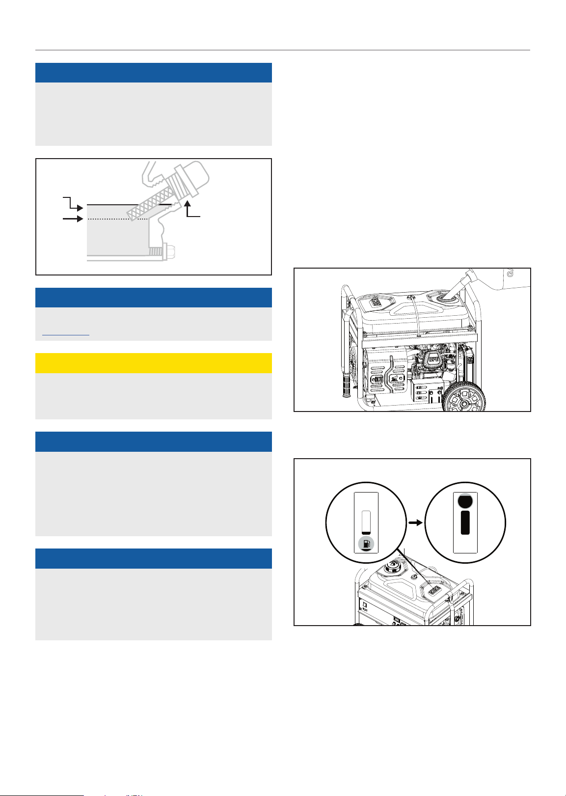
NOTICE
Once oil has been added, a visual check should show oil
about 1-2 threads from running out of the fill hole.
When using the dipstick to check oil level, DO NOT screw in
the dipstick while checking.
MAX
MIN
"
NOTICE
Check oil level often during the break-in period. Refer to the
Maintenance section for recommended service intervals.
OIL DIP STICK
Add Fuel
Use clean, fresh, regular unleaded gasoline with a minimum
octane rating of 85 and an ethanol content of 10% or less by
volume. ybc
DO NOT mix oil with gasoline.
1. Remove the gasoline cap.
2. Slowly add gasoline to the tank. Tank is full when gasoline
reaches red circle on screen. DO NOT OVERFILL. Gasoline
can expand after filling. A minimum of ¼ in. (6.4 mm) of
space left in the tank is required for gasoline expansion,
although more than ¼ in. (6.4 mm) is recommended.
Gasoline can be forced out of the tank as a result of
expansion if overfilled, and can affect the stable running
condition of the generator.
! CAUTION
This engine is equipped with a low oil shut-off and will stop
when the oil level in the crankcase falls below the threshold
level.
"
NOTICE
The first 5 hours of run time are the break-in period for the
unit. During the break in period stay at or below 50% of the
running watt rating and vary the load occasionally to allow
stator windings to heat and cool. Adjusting the load will also
cause engine speed to vary slightly and help seat piston
rings. After the 5 hour break-in period, change the oil.
"
NOTICE
Synthetic oil may be used after the 5 hour initial break-in
period. Using synthetic oil does not increase the
recommended oil change interval. Full synthetic 5W-30
oil will aid in starting in cold ambient < 41ºF (5ºC)
temperatures.
3. The approximate fuel level is shown on the fuel gauge on
top of the fuel tank.
EMPTY FULL
4. Screw on the gasoline cap and wipe away any spilled fuel.
18
Page 19

100554 - 3500W WIRELESS START GENERATOR
OPERATION
! CAUTION
Use unleaded gasoline with a minimum octane rating of 85
and an ethanol content of 10% or less by volume.
DO NOT light cigarettes or smoke when filling the tank.
DO NOT mix oil and gasoline.
DO NOT overfill the tank. Fill tank to approximately ¼ in.
(6.4 mm) below the top of the tank to allow for gasoline
expansion.
DO NOT pump gasoline directly into the generator at the
pump. Use an approved container to transfer the gasoline to
the generator.
DO NOT fill tank indoors.
DO NOT fill tank when the engine is running or hot.
! WARNING
Pouring gasoline too fast through the fuel screen may result
in gasoline splashing over the generator and operator while
filling.
"
NOTICE
The generator engine works well with 10% or less ethanol
blend gasoline. When using ethanol-gasoline blends there
are some issues worth noting:
– Ethanol-gasoline blends can absorb more water than
gasoline alone.
– These blends can eventually separate, leaving water or
a watery goo in the tank, fuel valve and carburetor. The
compromised gasoline can be drawn into the carburetor
and cause damage to the engine and/or potential
hazards.
– If a fuel stabilizer is used, confirm that it is formulated to
work with ethanol-gasoline blends.
– Any damages or hazards caused by using improper
gasoline, improperly stored gasoline, and/or
improperly formulated stabilizers, are not covered by
manufacturer’s warranty.
It is advisable to always shut off the gasoline supply and
run the engine to starvation after each use. See Storage
instructions for extended non-use.
Grounding
Your generator must be properly connected to an appropriate
ground to help prevent electric shock.
! WARNING
Failure to properly ground the generator can result in
electric shock.
A ground terminal connected to the frame of the generator has
been provided (see Controls and Features for terminal location).
For remote grounding, connect of a length of heavy gauge
(12 AWG minimum) copper wire between the generator ground
terminal and a copper rod driven into the ground. We strongly
recommend that you consult with a qualified electrician to
ensure compliance with local electrical codes.
Neutral Floating*
– Neutral circuit IS NOT electrically connected to the frame/
ground of the generator.
– The generator (stator winding) is isolated from the frame
and from the AC receptacle ground pin.
– Electrical devices that require a grounded receptacle pin
connection will not function if the receptacle ground pin is
not functional.
Neutral Bonded to Frame*
– Neutral circuit IS electrically connected to the frame/ground
of the generator.
– The generator system ground connects lower frame
cross-member below the alternator. The system ground is
connected to the AC neutral wire.
* See your model’s control panel for specified type of grounding.
OPERATION
Generator Location
NEVER operate the generator inside any building, including
garages, basements, crawlspaces and sheds, enclosure or
compartment, including the generator compartment of a
recreational vehicle. Please consult your local authority. In
some areas, generators must be registered with the local
utility. Generators used at construction sites may be subject
to additional rules and regulations. Generators should be on
a flat, level surface at all times. (Even while not in operation)
Generators must have at least 5 ft. (1.5 m) of clearance from
all combustible material. In addition to clearance from all
combustible material, generators must also have at least 3 ft.
(91.4 cm) of clearance on all sides to allow for adequate cooling,
maintenance and servicing. Generators should never be started
or operated in the back of a SUV, camper, trailer, in the bed of
a truck (regular, flat or otherwise), under staircases/stairwells,
19
Page 20
100554 - 3500W WIRELESS START GENERATOR
OPERATION
next to walls or buildings, or in any other location that will not
allow for adequate cooling of the generator and/or the muffler.
DO NOT contain generators during operation. Allow generators
to properly cool before transport or storage.
Place the generator in a well-ventilated area. DO NOT place the
generator near vents or intakes where exhaust fumes could
be drawn into occupied or confined spaces. Carefully consider
wind and air currents when positioning generator.
Failure to follow proper safety precautions may void
manufacturer’s warranty.
! WARNING
Do not operate or store the generator in rain, snow, or wet
weather.
Using a generator or electrical appliance in wet conditions,
such as rain or snow, or near a pool or sprinkler system,
or when your hands are wet, could result in electrocution.
! WARNING
During operation the muffler and exhaust fumes will
become hot. If adequate cooling and breathing space are
not supplied, or if the generator is blocked or enclosed,
temperatures can become extremely heated and may lead
to fire.
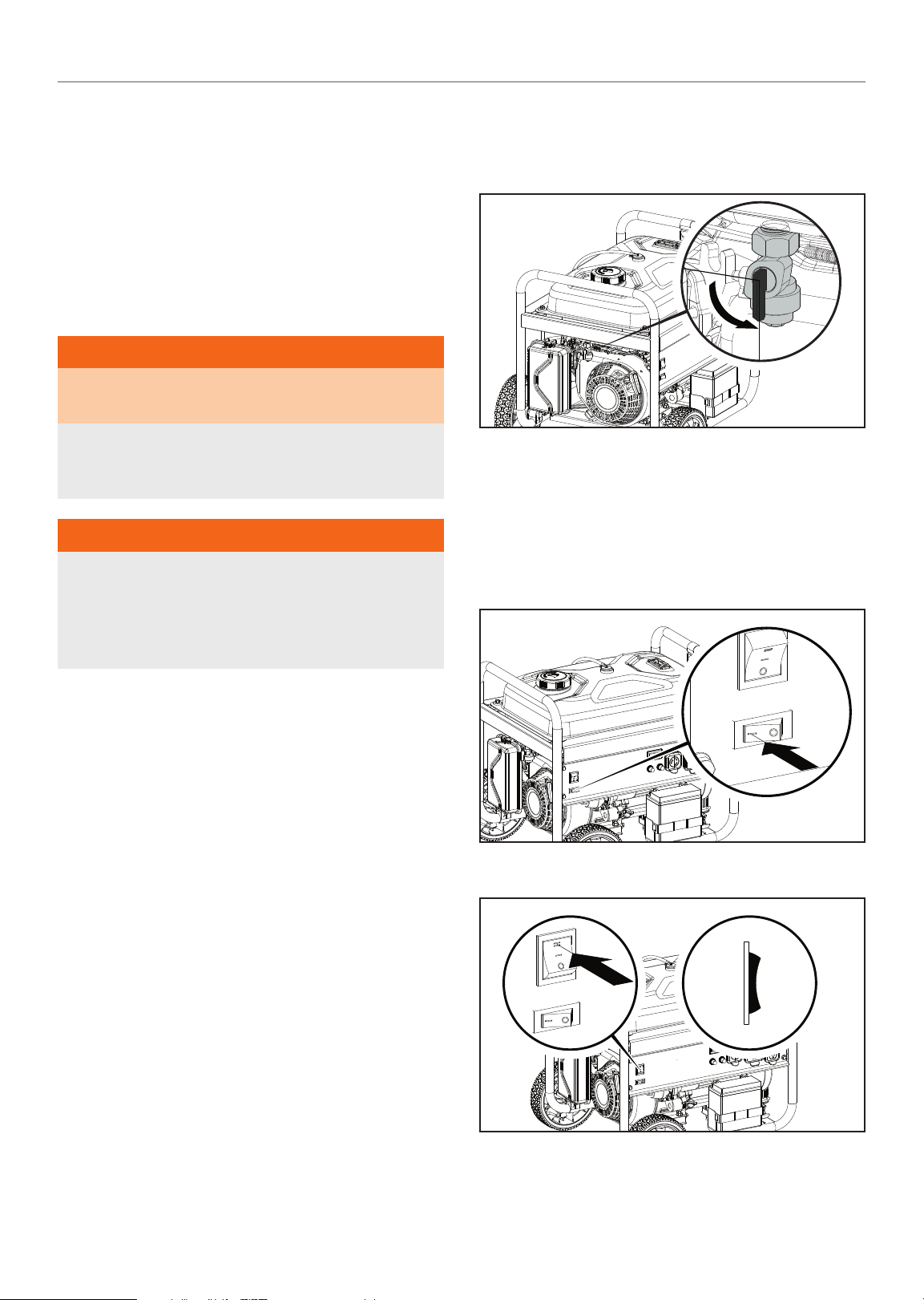
Starting the Engine
1. Make certain the generator is on a flat, level surface.
2. Tur n t he gasoline f uel valve to the “ON” p osi tio n.
Wireless Remote Start
Wireless remote starting is only possible within 80 feet of the
generator.
DO NOT attempt to adjust the choke. The remote system will
automatically close and open the choke.
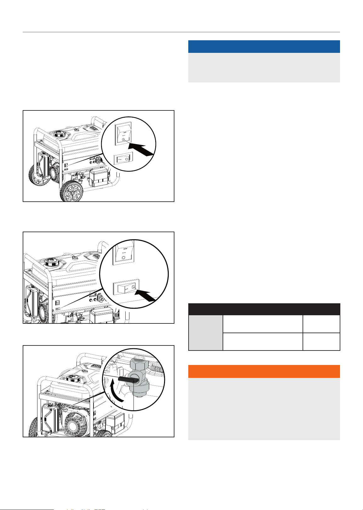
1. Push the battery switch to the “ON” position.
Surge Protection
Electronic devices, including computers and many
programmable appliances use components that are designed
to operate within a narrow voltage range and may be affected
by momentary voltage fluctuations. While there is no way to
prevent voltage fluctuations, you can take steps to protect
sensitive electronic equipment.
– Install UL1449, CSA-listed, plug-in surge suppressors on the
outlets feeding your sensitive equipment.
Surge suppressors come in single- or multi-outlet styles.
They’re designed to protect against virtually all shortduration voltage fluctuations.
2. Push the ignition switch to the “ON” position.
20
Page 21

100554 - 3500W WIRELESS START GENERATOR
OPERATION
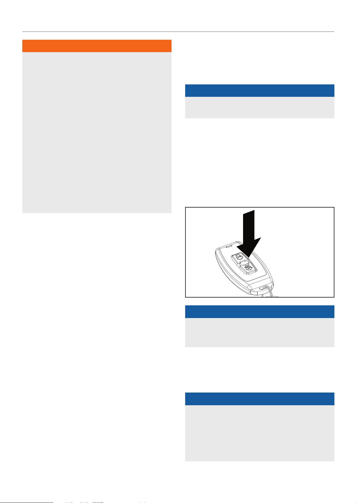
3. Press and release the “START” button on the remote
control. DO NOT hold the button down, only press the
button once. The engine will attempt to start six times.
Electric Start
DO NOT attempt to adjust the choke. The remote system will
automatically close and open the choke.
1. Push the battery switch to the “ON” position.
! CAUTION
If the ignition switch is held down in the “START” position
longer than 5 seconds it could damage the starter.
Manual Start
1. Disconnect all electrical loads from the generator. Never
start or stop the generator manually with electrical devices
plugged in or turned on.
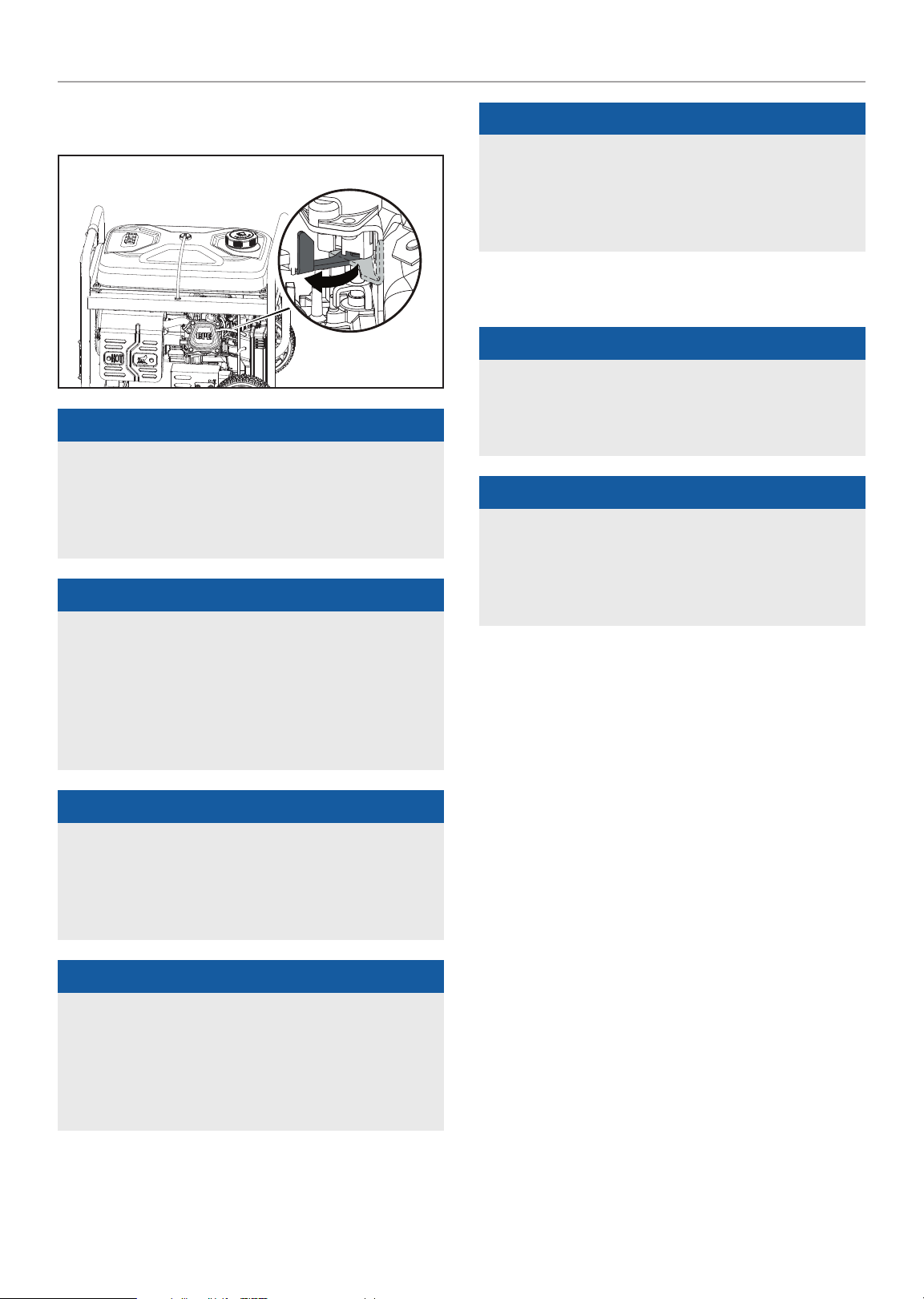
2. Move the choke to the “CHOKE” position.
2. Press and hold the ignition switch to the “START” position.
Release as the engine begins to start. If the engine fails
to start within five seconds, release the switch and wait
at least ten seconds before attempting to start the engine
again.
3. For restarting a warm engine, move the choke to 75% of
the “CHOKE” position.
4. Push the ignition switch to the “ON” position.
5. Pull the starter cord slowly until resistance is felt and then
pull rapidly
21
Page 22
100554 - 3500W WIRELESS START GENERATOR
OPERATION
6. Do not over-choke. As soon as engine starts, move the
choke to the “RUN” position over a 2-5 second duration.
"
NOTICE
Keep choke in “CHOKE” position for only 1 pull of the recoil
starter. After first pull, move choke to “RUN” position for
up to 3 pulls of the recoil starter. Too much choke leads to
spark plug fouling/engine flooding due to lack of incoming
air. This will cause the engine not to start.
"
NOTICE
For gasoline restarts with hot engine in hot ambient
temperature > 86°F (30°C), keep choke in 75% of the
“CHOKE” position for only 1 pull of the recoil starter. After
first pull, move choke to “RUN” position for up to 3 pulls
of the recoil starter. Too much choke leads to spark plug
fouling/engine flooding due to lack of incoming air. This will
cause the engine not to start.
"
NOTICE
If the engine starts but does not continue to run make
certain that the generator is on a flat, level surface. This
engine is equipped with a low oil sensor that will prevent the
engine from running when the oil level falls below a critical
threshold.
Battery
"
NOTICE
When the battery switch is in the “ON” position, the switch
will light up if the battery is sending out a charge. If the
switch does not light up while in the “ON” position, check
that the battery connection is still good.
"
NOTICE
The supplied 12V battery does re-charge while the engine
is running and the battery switch is turned ON, but it is also
recommended that the battery be fully charged at least once
per month or maintained with a trickle charger or battery
maintainer (not included).
Connecting Electrical Loads
Let the engine stabilize and warm up for a few minutes after
starting.
Plug in and turn on the desired 120 or 240 (if applicable) Volt AC
single phase, 60 Hz electrical loads.
"
NOTICE
For gas starting in cold ambient temperature < 59°F
(15°C), the choke must be in 100% of “CHOKE” position
for recoil start procedures. Do not over-choke. As soon as
engine starts, gradually move the choke lever to the “RUN”
position over a 2-5 second duration.
"
NOTICE
For Wireless and Electric Start only: A safety feature
is provided which delays the electrical power availability
during starting mode. The delay lasts for approximately 15
seconds. The delay is provided to prevent damage to the
generator if electrical loads are inadvertently turned on
during engine startup.
– DO NOT connect 3-phase loads to the generator.
– DO NOT overload the generator.
22
Page 23
100554 - 3500W WIRELESS START GENERATOR
OPERATION
! WARNING
Connecting a generator to your electric utility company’s
power lines or to another power source may be against
the law. In addition this action, if done incorrectly, could
damage your generator and appliances and could cause
serious injury or even death to you or a utility worker who
may be working on nearby power lines. If you plan to run a
portable electric generator during an outage, please notify
your electric utility company immediately and remember to
plug your appliances directly into the generator. Do not plug
the generator into any electric outlet in your home. Doing
so could create a connection to the utility company power
lines. You are responsible for ensuring that your generator’s
electricity does not feed back into the electric utility power
lines.
If the generator will be connected to a building electrical
system, consult your local utility company or a qualified
electrician. Connections must isolate generator power from
utility power and must comply with all applicable laws and
codes.
4. Allow the engine to stabilize.
5. Plug in and turn on the next item.
6. Allow the engine to stabilize.
7. Repeat steps 5-6 for each additional item.
"
NOTICE
Never exceed the specified capacity when adding loads to
the generator.
Stopping the Engine
Remote Stop
1. Turn off all electrical connected loads. Never start or stop
the generator with electrical devices turned on.
2. Let the generator run at no-load for several minutes to
stabilize internal temperatures of the engine and generator.
3. Press the “STOP” button on the remote.
Do Not Overload Generator
Capacity
Follow these simple steps to calculate the running and starting
watts necessary for your purposes:
1. Select the electrical devices you plan on running at the
same time.
2. Total the running watts of these items. This is the amount
of power you need to keep your items running.
3. Identify the highest starting wattage of all devices
identified in step 1. Add this number to the number
calculated in step 2. Starting wattage is the surge of power
needed to start some electric driven equipment. Following
the steps listed under “Power Management” will guarantee
that only one device will be starting at a time.
Power Management
Use the following formula to convert voltage and amperage to
watts:
Volts × Amps = Watts
To prolong the life of your generator and attached devices,
follow these steps to add electrical load:
1. Start the generator with no electrical load attached.
2. Allow the engine to run for several minutes to get up to
temperature.
3. Plug in and turn on the first item. It is best to attach the
item with the largest load first.
"
NOTICE
Engine will shut off but the battery switch, ignition switch,
and fuel valve will remain in the “ON” position waiting for
the next start instruction.
To completely shut down t he generator, ma ke sure the ignition
switch, battery switch, and fuel valve are in the “OFF” position
when the generator will not be used for an extended period of
time.
"
NOTICE
Battery power is drawn while the generator is in standby
mode (battery switch ON).
Do not leave generator in standby mode for an extended
period of time or the battery will be completely drained and
the wireless remote and electric start feature will no longer
function.
23
Page 24
100554 - 3500W WIRELESS START GENERATOR
OPERATION
Manual Stop
1. Tur n off an d unplug all electrical connec ted l oads. Never
start or stop the generator with electrical devices plugged
in or turned on.
2. Let the generator run at no-load for several minutes to
stabilize internal temperatures of the engine and generator.
3. Press the ignition switch to the “OFF” position.
4. If generator was started electrically, press the battery
switch to the “OFF” position.
"
NOTICE
If the engine will not be used for a period of two (2) weeks or
longer, please see the Storage section for proper engine and
fuel storage.
Operation at High Altitude
The density of air at high altitudes is lower than at sea level.
Engine power is reduced as the air mass and air-fuel ratio
decrease. Engine power and generator output will be reduced
approximately 3½% for every 1000 ft. of elevation above sea
level. At high altitudes increased exhaust emissions can also
result due to the increased enrichment of the air fuel ratio.
Other high altitude issues can include hard starting, increased
fuel consumption and spark plug fouling.
To alleviate high altitude issues other than the natural power
loss, CPE can provide a high altitude carburetor main jet.
The alternative main jet and installation instructions can be
obtained by contacting our Technical Support Team. Installation
instructions are also available in the Technical Bulletin area of
the CPE website.
5. Tur n the fuel valve to the “OFF” pos iti on.
The part number and recommended minimum altitude for the
application of the high altitude carburetor main jet is listed in
the following table.
In order to select the correct high altitude main jet it is
necessary to identify the carburetor model. For this purpose,
a code is stamped on the side of the carburetor. Select the
correct high altitude jet part number corresponding to the
carburetor code found on your particular carburetor.
Carb. Code High Alt. Jet Part Number Min. Altitude
100 082378
Z926-1
100123767
3281 ft.
(1000 m)
6562 ft.
(2000 m)
! WARNING
Operation using the alternative main jet at elevations lower
than the recommended minimum altitude can damage the
engine. For operation at lower elevations, the originally
supplied standard main jet must be used. Operating the
engine with the wrong engine configuration at a given
altitude may increase its emissions and decrease fuel
efficiency and performance.
Important: Always ensure that the fuel valve, the ignition
switch, and the battery switch are in the “OFF” position when
the generator will not be used for an extended period of time.
24
Page 25

100554 - 3500W WIRELESS START GENERATOR
MAINTENANCE
MAINTENANCE
Make certain that the generator is kept clean and stored
properly. Only operate the unit on a flat, level surface in a clean,
dry operating environment. DO NOT expose the unit to extreme
conditions, excessive dust, dirt, moisture or corrosive vapors.
! WARNING
Never operate a damaged or defective generator.
! WARNING
Improper maintenance will void your warranty.
"
NOTICE
For Emission control devices and systems, read and
understand your responsibilities for service as stated in the
Emission Control Warranty Statement of this manual.
The owner/operator is responsible for all periodic maintenance.
Complete all scheduled maintenance in a timely manner.
Correct any issue before operating the generator.
For service or parts assistance, contact our
Technic al Support Team at 1-877-338 -0999.
Cleaning the Generator
! CAUTION
1. Remove the oil drain bolt and washer with a 10 mm socket
(not included) and extension.
2. Allow the oil to drain completely into an appropriate
container.
DRAIN BOLT
WASHER
3. Replace the oil drain bolt and washer.
4. Remove the oil fill cap/dipstick to add oil.
5. Add oil according to “Add Engine Oil” on Assembly
section. DO NOT OVERFILL. Oil not included for routine
maintenance.
6. Dispose of used oil at an approved waste management
facility.
"
NOTICE
Once oil has been added, a visual check should show oil
about 1-2 threads from running out of the fill hole. If using
the dipstick to check oil level, DO NOT screw in the dipstick
while checking.
DO NOT spray generator directly with water.
Water can enter the generator through the cooling slots and
damage the generator windings. It can also contaminate the
fuel system.
1. Use a damp cloth to clean exterior surfaces of the
generator.
2. Use a soft bristle brush to remove dirt and oil.
3. Use an air compressor (25 PSI) to clear dirt and debris
from the generator.
4. Inspect all air vents and cooling slots to ensure that they
are clean and unobstructed.
To prevent accidental starting, remove and ground the spark
plug wire before performing any service.
Changing the Engine Oil
Change oil when the engine is warm. Refer to the oil
specification to select the proper grade for your operating
environment.
Cleaning and Adjusting the Spark Plug
1. Remove the spark plug cable from the spark plug.
2. Use a spark plug socket tool (not included), or a
13/16 in. (21 mm) socket (not included) to remove the plug.
3. Inspect the electrode on the plug. It must be clean and not
worn to produce the spark required for ignition.
4. Make certain the spark plug gap is
0.024-0.031 in. (0.6-0.8 mm).
SPARK PLUG GAP
5. Refer to the spark plug types in Specifications when
replacing the plug.
25
Page 26
100554 - 3500W WIRELESS START GENERATOR
MAINTENANCE
6. Firmly re-install the plug.
7. Attach the spark plug cable to the spark plug.
Cleaning the Air Filter
1. Remove the snap-on cover holding the air filter to the
assembly.
2. Remove the foam element.
3. Wash in liquid detergent and water. Squeeze thoroughly dry
in a clean cloth.
4. Saturate in clean engine oil.
5. Squeeze in a clean, absorbent cloth to remove all excess
oil.
6. Place the filter in the assembly.
7. Reattach the air filter cover and snap in place.
Cleaning the Spark Arrestor
1. Allow the engine to cool completely before servicing the
spark arrestor.
2. Remove the two or three screws (varies by model) holding
the cover plate which retains the spark arrestor to the
muffler.
3. Remove the spark arrestor screen.
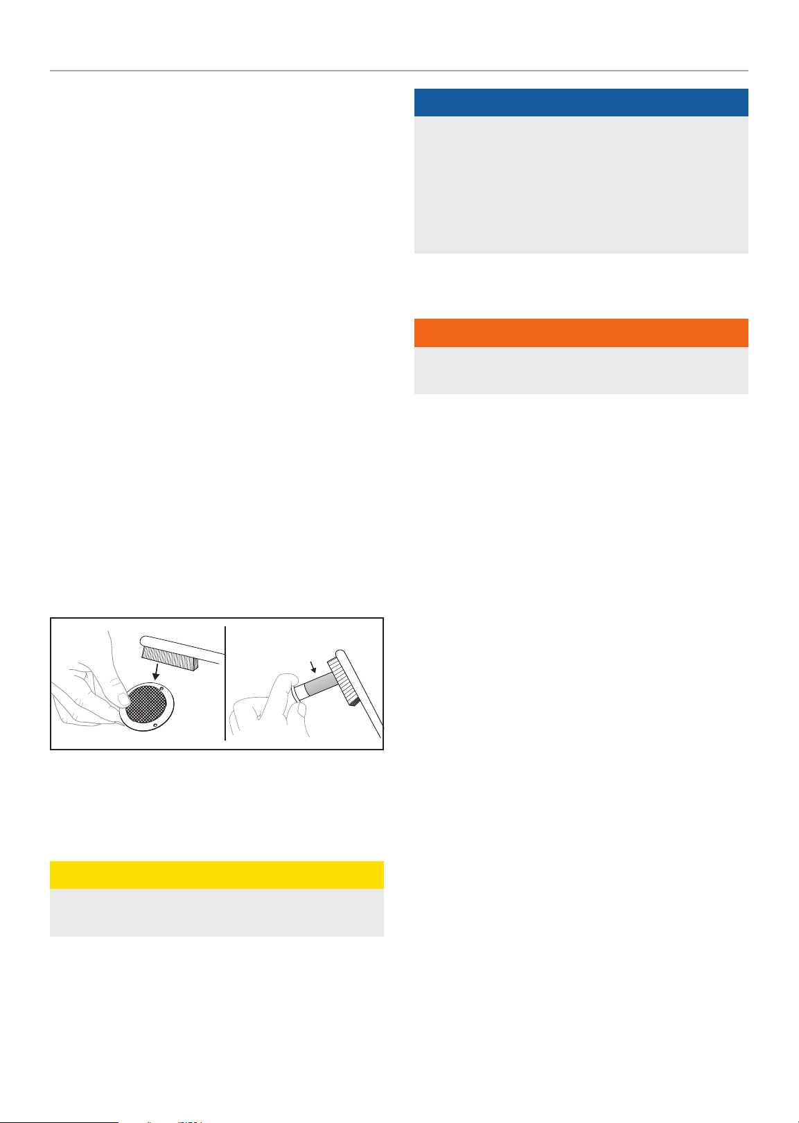
4. Carefully remove the carbon deposits from the spark
arrestor screen with a wire brush.
Type 1 Type 2
"
NOTICE
Federal and local laws and administrative requirements
indicate when and where spark arrestors are required.
When ordered, spark arrestors are required for operation
of this generator in National Forest lands. In California,
this generator must not be used on any forest-covered
land, brush-covered land, or grass-covered land unless the
engine is equipped with a spark arrestor.
Adjusting the Governor
! WARNING
Tampering wit h the factory set governor will void your
warranty.
The air-fuel mixture is not adjustable. Tampering with
the governor can damage your generator and your
electrical devices and will void your warranty. Contact our
Technical Support Team at 1-877-338-0999 for all other
service and/or adjustment needs.
Generator Battery
Your generator is equipped with an automatic battery charging
circuit that charges the battery while the engine is running.
The battery will maintain a proper charge if the unit is used on
a regular basis (about once every two weeks). If it is used less
frequently, the battery should be connected to a trickle charger
or battery maintainer (not included) to keep the battery properly
charged.
* See your model’s parts list for specified type of spark arrestor.
5. Replace the spark arrestor if it is damaged.
6. Position the spark arrestor on the muffler and attach with
the screws removed in step 2.
! CAUTION
Failure to clean the spark arrestor will result in degraded
engine performance.
Maximum charging rate should not exceed 1.5 amps. Follow
the instructions included with the battery charger. The battery
should be fully charged at least once per month. If the battery
is not able to start the engine, it can be started by manually
pulling the engine recoil cord. If the battery voltage is extremely
low, the charging circuit may not be able to re-charge the
battery. In this case, the battery must be connected to a
standard automotive style battery charger for re-charging
before it can be used.
Disconnect the Battery
1. Remove the protective cover from the black (–) battery
lead.
2. Disconnect the black (–) lead from the black (–) terminal on
the battery and store the cap screw and nut.
3. Repeat steps 1-2 for the red (+) battery lead.
4. Store the battery in a cool, dry place.
Charge the Battery
For a generator equipped with batteries for electric starting,
proper battery maintenance and storage should be followed.
26
Page 27

100554 - 3500W WIRELESS START GENERATOR
STORAGE
A trickle charger or battery maintainer should be used to charge
the battery while the generator is in storage. Maximum charging
rate should not exceed 1.5 amps. Follow the instructions
included with the trickle charger or battery maintainer.
The battery should be fully charged at least once per month.
Remote Control Battery
"
NOTICE
– Always purchase the correct size and grade of battery
most suitable for the intended use.
– Clean the battery contacts and also those of the device
prior to battery installation.
– Remove batteries from equipment which is not to be
used for an extended period of time.
– Remove batteries if consumed or if product is to be left
unused for a long time.
Maintenance Schedule
Follow the service intervals indicated in the following
maintenance schedule.
Service your generator more frequently when operating in
adverse conditions.
EVERY 250 HOURS
# Clean combustion chamber**
EVERY 3 YEARS
# Replace fuel line*
* To be p erfo rmed by knowledgeabl e, experie nced owners or C PE cert ifie d
service centers.
STORAGE
! DANGER
Gasoline vapors are highly flammable and extremely
explosive.
Fire or explosion can cause severe burns or death. Only
fill or drain fuel outdoors in a well-ventilated area. DO NOT
pump gasoline directly into the generator. Use an approved
container to transfer the fuel to the generator. Never use
a gasoline container, gasoline tank, or any other fuel item
that is damaged or appears damaged. DO NOT overfill the
gasoline tank. Always keep fuel away from sparks, open
flames, pilot lights, heat and other sources of ignition.
DO NOT light or smoke cigarettes.
Contact our Technical Support Team at 1-877-338-0999
to locate the nearest CPE certified service dealer for your
generator or engine maintenance needs.
EVERY 8 HOURS OR PRIOR TO EACH USE
# Check oil level
# Clean around air intake and muffler
FIRST 5 HOURS (BREAK IN)
# Change oil
EVERY 50 HOURS OR ANNUALLY
# Clean air filter
# Change oil if operating under heavy load or in hot
environments
EVERY 100 HOURS OR ANNUALLY
# Change oil
# Clean/adjust spark plug
# Check/adjust valve clearance*
# Clean spark arrestor
# Clean fuel tank and filter*
Short Term Storage (up to 30 days)
Gasoline may gum up and clog the carburetor if the generator is
not run or carburetor drained within 4 weeks.
1. Be sure all appliances are disconnected from the generator.
2. Start the generator as instructed in “Starting the Engine”
section.
3. Turn the fuel valve t o t he “O FF” posi tio n.
4. Let the engine run until fuel starvation has stopped the
engine. This usually takes a few minutes.
5. Move the ignition switch to the “OFF” position.
Mid Term Storage (30 days – 1 year)
Gasoline in the tank has a maximum shelf life of up to 1 year
with the addition of a properly formulated fuel stabilizer and
stored in a cool, dry place.
1. Be sure all appliances are disconnected from the generator.
2. Add a properly formulated fuel stabilizer to the gasoline
tank.
3. Turn the fuel valve t o t he “O N” pos iti on.
4. Start and run the generator for 10 minutes so the treated
gasoline cycles through the fuel system.
27
Page 28
100554 - 3500W WIRELESS START GENERATOR
STORAGE
5. Option 1: Drain Gasoline from Carburetor
5a. Turn ignition switch t o t he “OFF ” p osi tio n a nd allow
generator to cool completely before continuing.
5b. Turn the fuel valve to the “OFF”.
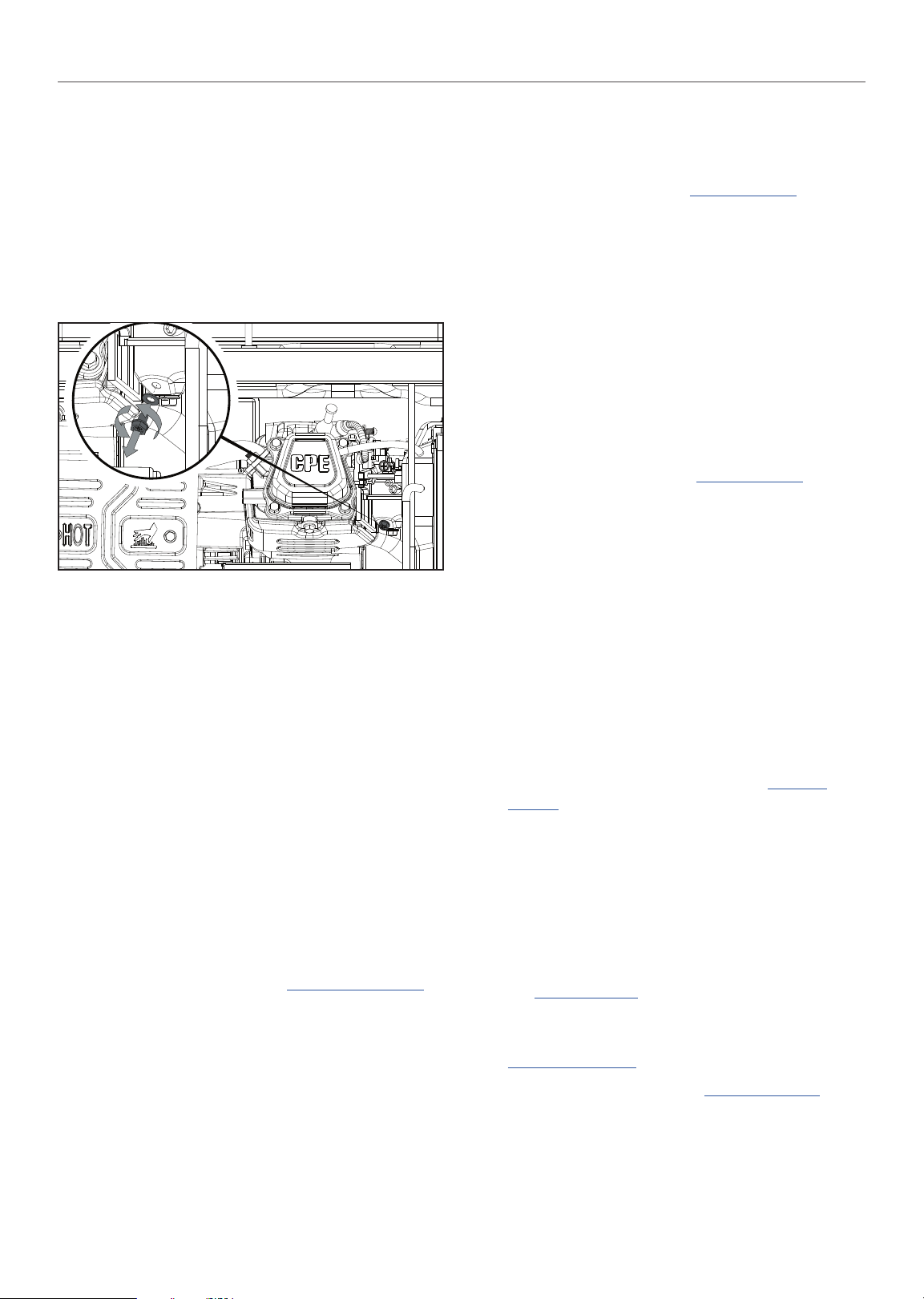
5c. Use the drain bolt on the carburetor to empty any
excess gasoline from the carburetor into an appropriate
container. Use a funnel (and appropriate hose if
necessary) under the carburetor drain bolt to avoid
spillage.
5d. When gasoline stops flowing from the carburetor,
replace and tighten the carburetor drain bolt and
be sure to properly dispose of the drained gasoline
according to local regulations or guidelines.
6. Option 2: Run Dry
6a. With the generator running, turn the fuel valve to the
“OFF” position and allow the generator to run until the
engine stops from complete fuel starvation. This may
take a few minutes.
6b. Turn ignition swit ch to th e “OFF” posi tion and allow
generator to cool completely before continuing.
7. Remove the spark plug cap and spark plug and pour about
a tablespoon of oil into the cylinder.
8. Pull the recoil slowly to crank the engine to distribute the
oil and lubricate the cylinder.
9. Install the spark plug and spark plug cap.
10. Clean the generator according to Cleaning the Generator.
11. Store the generator in a cool, dry place out of direct
sunlight.
Long Term Storage (over 1 year)
For storage over 1 year, the gasoline tank and carburetor must
be completely drained of gasoline.
1. Follow steps 1-4 according to Mid Term Storage.
1a. Turn ignition switch to the “OFF” position and allow
generator to cool completely before continuing.
2. Use the drain bolt on the carburetor to empty any excess
gasoline from the gasoline tank and carburetor into an
appropriate container. Use a funnel (and appropriate hose if
necessary) under the carburetor drain bolt to avoid spillage.
3. When gasoline stops flowing from the carburetor, replace
and tighten the carburetor drain bolt and be sure to
properly dispose of the drained gasoline according to local
regulations or guidelines.
4. Tur n t he fuel valve to the “OFF” position.
5. Follow steps 8-11 according to Mid Term Storage.
Removing from Storage
If the generator has been improperly stored for a long period
of time with gasoline in the gasoline tank and/or carburetor, all
fuel must be drained and the carburetor must be thoroughly
cleaned. This process involves technically advanced tasks.
For assistance please call our Technical Support Team at
1-877-338-09 99.
If the gasoline tank and carburetor were properly emptied of all
gasoline prior to the generator being stored, follow the below
steps when removing from storage.
1. Be sure the ignition switch is in the “OFF” position.
2. Add gasoline to the generator according to Add Fuel:
Gasoline.
3. Turn the fuel valve t o t he “O N” pos iti on.
4. After 5 minutes check the carburetor and air filter areas for
any leaking gasoline. If any leaks are found, the carburetor
will need to be disassembled and cleaned or replaced. If no
gasoline leaks are found, turn the fuel valve to the “OFF”
position.
5. Check engine oil level and add clean, fresh oil if needed.
See Oil Specifications for proper oil type.
6. Check and clear air filter of any obstructions such as bugs
or cobwebs. If necessary, clean air filter according to
Cleaning the Air Filter.
7. Start the generator according to Starting the Engine.
28
Page 29

100554 - 3500W WIRELESS START GENERATOR
SPECIFICATIONS
SPECIFICATIONS
Generator Specifications
Generator Model ........................................ 100554
Start Type ............................ Manual, Electric, Wireless
Watts (Starting/Running) ........................... 4375/3500
AC Volts ....................................................... 120
AC Amps @ 120V ........................................... 29.2
Frequency .................................................. 60 Hz
Phase .......................................................Single
Weight ........................................ 120.1 lb. (54.5 kg)
Length .........................................24.9 in. (63.2 cm)
Width ......................................... 22.9 in. (58.2 cm)
Height ..........................................22.4 in. (56.9 cm)
Engine Specifications
Model ...................................................... FH210
Displacement ..............................................208 cc
Type ................................................ 4-Stroke OHV
Spark Plug
OEM Type ........................................... NHSP F6RTC
Replacement Type ................... NGK BPR6ES or equivalent
Gap ...............................0.024-0.031 in. (0.6-0.8 mm)
Valve
Intake Clearance .............. 0.004-0.006 in. (0.10-0.15 mm)
Exhaust Clearance ............0.006-0.008 in. (0.15-0.20 mm)
"
NOTICE
A technical bulletin regarding valve adjustment procedures
is available at www.championpowerequipment.com.
"
NOTICE
Temperature will affect engine oil and engine performance.
Change the type of engine oil used based on the
temperature to suit the engine needs.
Fuel Specifications
Use unleaded gasoline with a minimum octane rating of 85 and
an ethanol content of 10% or less by volume. DO NOT USE E15
or E85. DO NOT OVERFILL.
Gasoline Capacity ............................... 4.7 gal. (17.8 L)
Battery Specifications
Type .....................Rechargeable, Non-Spillable Lead Acid
Volts ............................................................12
Capacity ..................................................... 9 Ah
Temperature Specifications
Starting Temperature Range (°F/°C) ........ 5 to 104/-15 to 40
Remote Starting Temperature
Range (°F/°C) ................................ 23 to 104/-5 to 40
"
NOTICE
An important message about temperature: Your product
is designed and rated for continuous operation at ambient
temperatures up to 104°F (40°C). When needed, it may be
operated at temperatures ranging from 5°F (-15°C) to 122°F
(50°C) for short periods of time. If exposed to temperatures
outside this range during storage, it should be brought back
within this range before operation. In any event, the product
must always be operated outdoors, in a well-ventilated area
and away from doors, windows and vents.
Oil Specifications
DO NOT OVERFILL.
Type ............................................ *See chart below
Capacity ..............................18.6 fl. oz. / 0.6 qt. (0.6 L)
Recommended Engine Oil Type
10W-30
10W-405W-30
5W-30 Synthetic
-20 0 20 40 60
°F
-28.9
°C -17.8 -6.7 4.4 15.6 26.7 37.8 48.9
Ambient temperature
80 100 120
29
Page 30
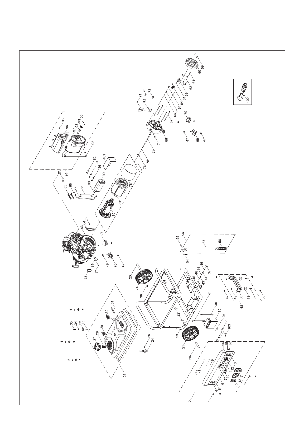
100554 - 3500W WIRELESS START GENERATOR
Parts Diagram
SPECIFICATIONS
30
Page 31

100554 - 3500W WIRELESS START GENERATOR
Parts List
SPECIFICATIONS
# Part Number Description Qty.
1 100 011261-0002
2 100 095516-00 01 Panel Assembly 1
3 100 021441
4 100 019771-0001 Switch 1
5 100 096134- 0001 Battery Switch 1
6 100 095896 Control Panel 1
7 100 0959 27 Intelligauge, VFT 1
8 100 019751
9 100 019754
10 100120180 Breaker Cover 2
11 100 020005 Receptacle L5-30R 1
12 10 0020008 Receptacle TT-30R 1
13 10 0020029
14 100021446 Learning Button 1
15 1000 21445 Remote Indicator 1
16 100020100 Protect Panel 1
17 10 0098921
18 1000 8826 8
19 1000 88269
20 100041170 -0001 Roll Pin Ø16 × 85 2
21 100092300 -0001 8 In. Wheel, Black 2
22 100023414-0001 R-pin 2
23 100095517-0001
24 100021153 Fuel Valve 1
25 100005138 Clamp Ø9.5 × 8 1
26 100095592- 0001
27 100093333 Fuel Tank Cap 1
28 100098838 Fuel Filter 1
29 100099571 Reversal Valve 1
30 100095894 Gauge, Fuel Level 1
31 100059920-0001
32 100021118
Flange Bolt M6 × 12,
Black Zinc
Remote Control
Assembly
30Amp Circuit Breaker,
Push Button
20Amp Circuit Breaker,
Push Button
Receptacle 5-20R,
Duplex
Receptacle Cover
5-20R, Duplex
Receptacle Cover
TT-30R
Receptacle Cover
L5-30R
Frame
590 × 464 × 505.5
Fuel Tank, 17.8 L,
Yellow
Label, Fuel Level
Gauge
Bushing,
Ø12 × Ø9 × 13
# Part Number Description Qty.
4
1
1
1
1
1
1
1
1
1
1
4
33 100032369
34 100010439-0001
35 100011268-0002
36 100009075 Rubber Damper 3
37 100010828-0002 Butterfly Type Nut M6 1
38 100099572-00 01 Pressing Plate, Battery 1
39 100122390 Battery, 12V 9Ah 1
40 100009990-0001 Negative Wire 1
41 100095628 Positive Wire 1
42 100009983
43 100011421-0003 Flange Nut M6 1
44 1000109 20 -0002 Flat Washer Ø6 2
45 100011025-0001
46 1000108 86-0004 Spring Washer Ø6 2
47 100011453-0003 Lock Nut M8, Flange 10
48 100020978-00 01 Support Leg Assembly 1
49 100011452-0003 Lock Nut M6, Flange 2
50 100020659-0001 Support Leg 1
51 100 021015 Vibration Mount 2
52 100011265- 0003 Flange Bolt M6 × 18 4
53 100011311-0005 Flange Bolt M8 × 16 2
54 100023415-0001 R-pin, R5 1
55 100011047-0003 Roll Pin Ø8 × 40 1
56 100086540-0001 Handle Assembly 1
57 100095941-0001 Handle 1
58 100031982 Sheath, Handle 1
59 100011250-00 02 Flange Bolt M5 × 14 2
60 1000186 58-0023
61 100011252-0001 Flange Bolt M5 × 18 6
62 100095626 AVR 1
63 100018592
64 100018701 Te rmin al Bl ock 1
65 1000108 85-0004 Spring Washer Ø5 1
66 100010919- 0002 Flat Washer Ø5 1
67 100011297-0002 Flange Bolt M6 × 165 4
68 100018567 End Housing 1
69 100020986-0 001
Vibration Mounting,
Fuel Tank
Washer
Ø6.5 × 2 × Ø25, Black
Flange Bolt M6 × 25,
Black
Grounding Line
150 mm
Lock Washer Ø6,
Too thed
Generator End Cover,
Yellow
Carbon Brush
Assembly
Vibration Mount,
Support 1
4
4
5
1
1
1
1
2
31
Page 32
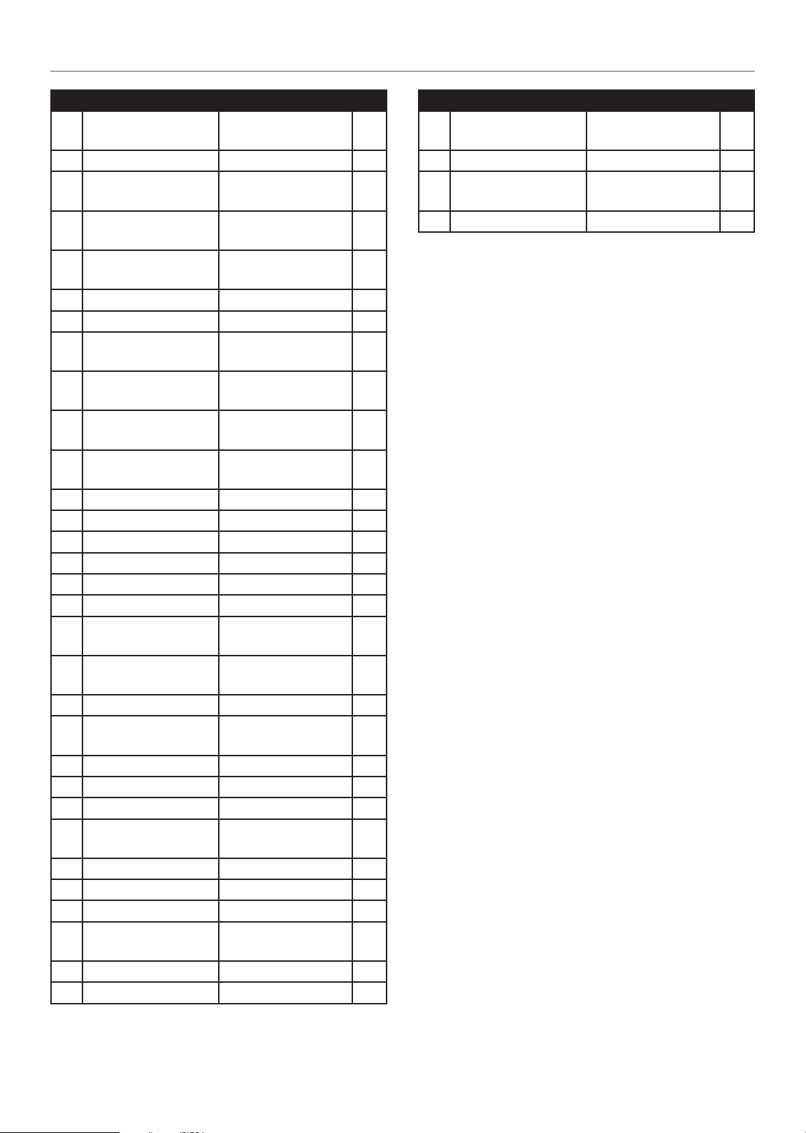
100554 - 3500W WIRELESS START GENERATOR
SPECIFICATIONS
# Part Number Description Qty.
70 100021000-0001
71 100011261-0004 Flange Bolt M6 × 12 4
72 100021068
73 100011230-00 02
74 10 0011375-0 001
75 100010887-0004 Spring Washer Ø8 1
76 100010899-00 02 Washer Ø8 1
77 100095623
78 100095943
79 100095944
80 100095942
81 100020165 Support, End Cover 1
82 100000657 Cable Clamp 1
83 1ZC7DF0N2 Engine, 208 cc 1
84 100021030 Holder, Air Cleaner 1
85 100000658 Clamp 2 2
86 100005148 Clamp 1 1
87 100095515
88 100095519
89 100005135 Clamp Ø11.5 × 10 2
90 100094372
91 100004241 Bushing Ø8.5 × 9 2
92 100011422-0 004 Flange Nut M8 2
93 100006936 Gasket, Exhaust Pipe 1
94 100087308
95 100097575-0001 Flange Bolt M6 × 10 4
96 100006811 Muffler Cover 1
97 100126717 Muffler 1
98 100006594
99 100006999 Plate, Spark Arrester 1
100 100 011247-0003 Flange Bolt M5 × 8 2
Vibration Mount,
Support 2
Mounting Plate
Support Assembly
Flange Bolt M8 × 16,
GB5787
Flange Bolt
M8 × 1 × 220
Alternator Assembly,
Al, Ø160 × 120 mm
Stator Cover,
112.5 mm
Stator Assembly, Al,
Ø160 × 120 mm
Rotor Assembly, Al,
Ø95 × 120 mm
Connection Tube 1,
800 mm
Connection Tube 2,
245 mm
Carbon Canister,
380 cc
Exhaust Muffler
Assembly
Spark Arrester
Assembly
# Part Number Description Qty.
2
1
2
1
1
1
1
1
1
1
1
1
1
101 10 0099411-0001
102 100 095629 Remote Control 1
103 100090978
104 100143536 Rubber Mat 1
Carbon Canister
Insulator
Butterfly Type Bolt
M6 × 16
1
1
32
Page 33
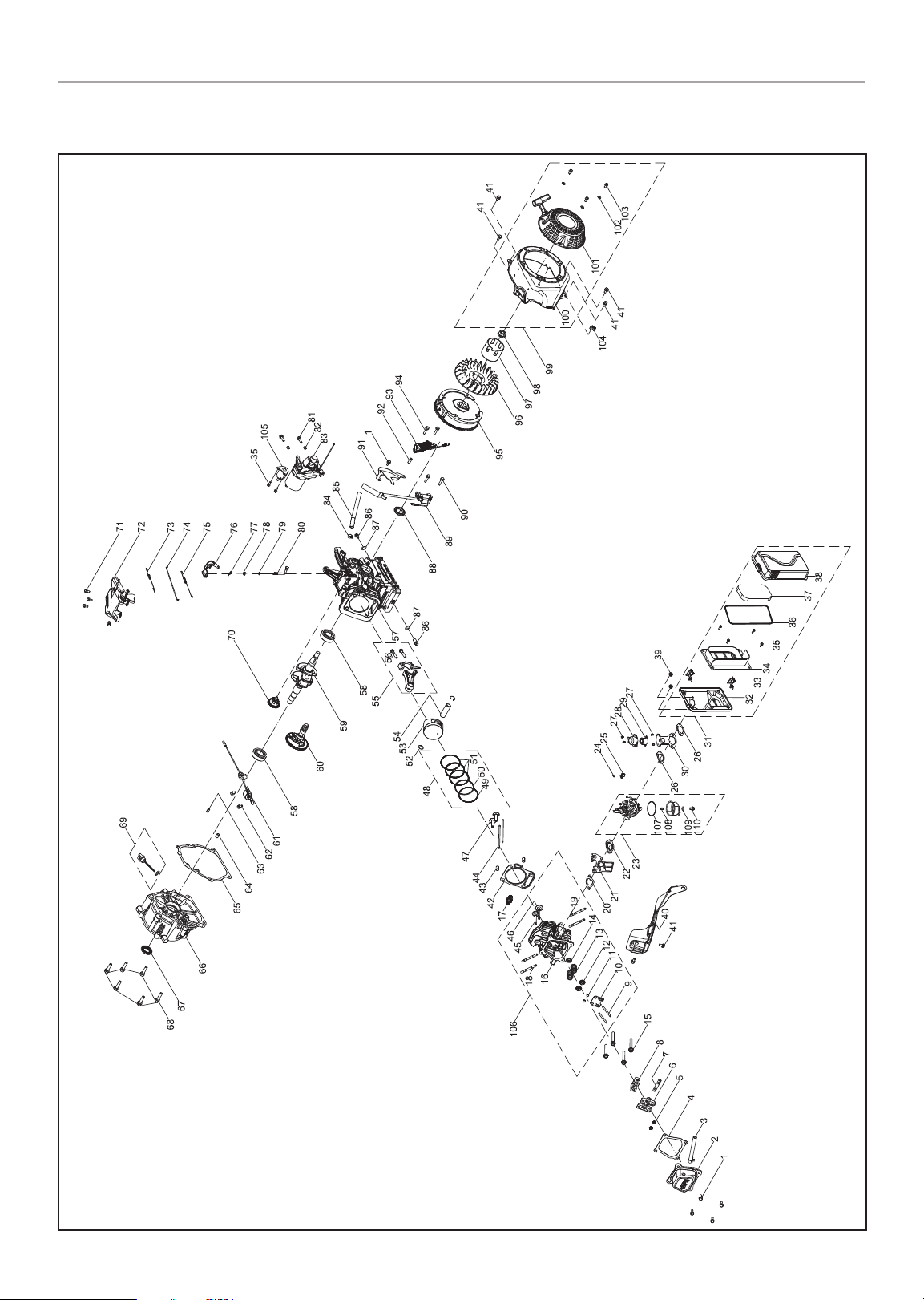
100554 - 3500W WIRELESS START GENERATOR
Engine Parts Diagram
SPECIFICATIONS
33
Page 34

100554 - 3500W WIRELESS START GENERATOR
Engine Parts List
SPECIFICATIONS
# Part Number Description Qty.
1 100 011264-0003
2 100 002335
3 100 031972 Breather Tube 1
4 100 066138
5 100 011463-0002 Flange Nut M6 2
6 100 004431 Rocker Arm Assembly 2
7 100 004512 Shaft, Rocker Arm 1
8 100 004506 Retainer, Rocker Arm 1
9 100 004505 Bolt, Rocker Arm 2
10 1000 04478 Guide Plate, Push Rod 1
11 100 004588
12 10 0004585
13 10 0004564 Spring, Valve 2
14 100004600 Oil Seal, Valve 1
15 1000 02464-0001 Flange Bolt M8 × 60 4
16 1000 02389 Cylinder Head 1
17 10 0009378 Spark Plug F6RTC 1
18 100010389 Stud Bolt M8 × 35 2
19 100010354 Stud Bolt M6 × 96 2
20 100092295 Gasket, Insulator 1
21 100005599 Insulator, Carburetor 1
22 100078606 Gasket, Carburetor 1
23 100094371 Carburetor 1
24 100052404 Spring 1
25 100007579
26 100066136 Gasket, Air Filter Base 2
27 100051029 -0001 Screw M4 × 6 4
28 100074044 Protection Cover 1
29 100061511 Stepping Motor 1
30 100095804 Mounting Bracing Plate 1
31 10000 4745 Air Filter Assembly 1
32 100005023 Air Filter Base 1
33 100004894 Air Filter Clip 2
34 100004877 Air Filter Separator 1
35 100011250-0002 Flange Bolt M5 × 14 6
36 100004795 Gasket, Air Filter Cover 1
37 100004770 Air Filter Element 1
38 100004873 Air Filter Cover 1
Flange Bolt M6 × 16,
GB5789
Cylinder Head
Cover(Cpe)
Gasket, Cylinder Head
Cover
Valve Adjust Cap,
Exhaust
Valve Spring Seat,
Exhaust
Clamp, Stepping Motor
Guide
# Part Number Description Qty.
5
1
1
2
2
1
39 100011452-0003 Lock Nut M6, Flange 2
40 100007111 Air Guide, Lower 1
41 100011261-0004
42 100010213 Gasket, Cylinder Head 1
43 1000105 58 Dowel Pin Ø10 × 16 2
44 100004408 Push Rod 2
45 100004550 Valve, Exhaust 1
46 100004524 Valve, Intake 1
47 100004263 Lifter, Valve 2
48 100003245 Piston Ring Set 1
49 100003150 1st Piston Ring 1
50 100003191 2nd Piston Ring 1
51 100 003283 Oil Ring 1
52 100003221 Circlip, Wrist Pin 2
53 100003081 Piston 1
54 100003125 Wrist Pin 1
55 100003448 Connecting Rod 1
56 100003430 Bolt, Connecting Rod 2
57 1000026 64 Crankcase 1
58 100010787 Bearing TM6205 - P63 2
59 100003770 Crankshaft 1
60 100092356 Camshaft 1
61 100010025 Oil Level Sensor 1
62 100011217-0 002 Flange Bolt M6 × 16 2
63 1000105 44 Dowel Pin Ø7 × 14 1
64 100010554 Dowel Pin Ø9 × 14 1
65 100092294
66 100002990 Cover, Crankcase 1
67 100017651
68 100011319- 0001 Flange Bolt M8 × 32 6
69 100004107-0001 Oil Dipstick Assembly 1
70 100008296 Gear, Governor 1
71 100011215-0001 Flange Bolt M6 × 12 4
72 100008186 Control Assembly 1
73 100007840 Spring, Governor 1
74 10 0007947 Rod, Governor 1
75 100007920 Spring, Throttle Return 1
76 100008417 Arm, Governor 1
77 100007986 Cotter, Governor Shaft 1
78 100017630 Oil Seal Ø6 × Ø11 × 4 1
Flange Bolt M6 × 12,
GB5789
Gasket, Crankcase
Cover
Oil Seal
Ø25 × Ø41.25 × 6
6
1
1
34
Page 35

100554 - 3500W WIRELESS START GENERATOR
# Part Number Description Qty.
79 100010113
80 100007975 Governor Shaft 1
81 100011223-00 01 Flange Bolt M6 × 32 2
82 100010547 Dowel Pin Ø8 × 8 2
83 100096311 Motor 1
84 100005138 Clamp Ø9.5 × 8 1
85 100017831
86 100010272
87 100010459
88 100017644
89 100009272 Ignition Module 1
90 100011268-0003 Flange Bolt M6 × 25 2
91 100007060 Lower Guard 1
92 100004217 Bushing Ø8 × Ø12 × 8 1
93 100009400 Charge Coil 1
94 100011269-0003 Bolt M6 × 28 2
95 100009535 Flywheel 1
96 100007028 Cooling Fan 1
97 100007550 Pulley, Starter 1
98 100011459-00 03 Flange Nut M14 × 1.5 1
99 100095986-0001
100 100 051113-0011 Fan Cover, Yellow 1
101 10 0099122-0001 Recoil Starter, Black 1
102 100 010894-0001 Washer Ø6 3
103 100011528-00 04 Flange Bolt M6 × 10 3
104 100 052808 Clamp 1
105 100120416 Start Relay 1
106 100127017
107 10 0082397 Fuel Bowl O-Ring 1
100123334 Main Jet Standard 1
100 082378
108
100123767
109 100 006039
110 100005725
Sealing Ring,
Ø5.2 × 1.9
Fuel Pipe,
Ø4 × Ø10 × 126
Drain Bolt,
M10 × 1.25 × 15
Washer
Ø10 × 1.5 × Ø16
Oil Seal Ø25 × Ø41.25
× 6, Spiral Grain
Recoil Starter
Assembly
Cylinder Head
Assembly
Main Jet Altitude
100 0-2000m
Main Jet Altitude
2000-3000m
Fuel Bowl Mounting
Bolt Gasket
Fuel Bowl Mounting
Bolt
SPECIFICATIONS
1
1
2
2
1
1
1
/
/
1
1
35
Page 36

100554 - 3500W WIRELESS START GENERATOR
Wiring Diagram
SPECIFICATIONS
36
Page 37
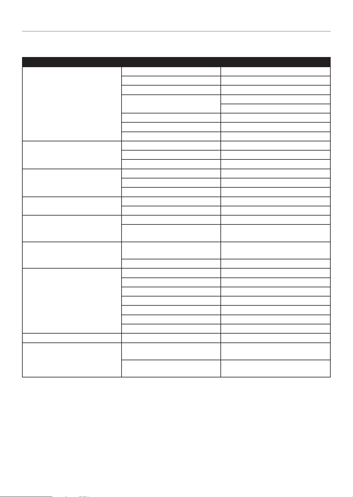
100554 - 3500W WIRELESS START GENERATOR
TROUBLESHOOTING
Problem Cause Solution
No fuel. Add fuel.
Faulty spark plug. Replace spark plug.
Unit loaded during start up. Remove load from unit.
Generator will not start.
Generator starts but runs roughly.
Generator will not start wirelessly.
Generator will not start electrically.
Generator shuts down during operation.
Generator cannot supply enough power
or overheating.
No AC output.
Generator hunts. Engine governor defective. Contact the help line.
Repeated circuit breaker tripping.
Low oil level.
Spark plug wire loose. Attach wire to spark plug.
Fuel valve is closed Open fuel valve.
Engine switch OFF. Tur n engine swi tch O N.
Choke in the wrong position. Adjust choke.
Dirty air filter. Clean or replace air filter.
Dirty fuel valve. Clean the fuel valve.
Remote control battery is dead. Replace remote control battery.
Generator battery is dead. Recharge generator battery
Battery switch is in the OFF position. Turn battery switch t o O N p osi tio n.
Generator battery is dead. Recharge generator battery.
Battery switch is in the OFF position. Turn battery switch t o O N p osi tio n.
Out of fuel. Fill fuel tank.
Low oil level.
Generator is overloaded.
Dirty air filter. Clean or replace air filter.
Power cord not properly connected. Check all connections.
Connected device is defective. Replace defective device.
Circuit breaker is open. Reset circuit breaker.
Faulty brush assembly. Replace brush assembly (Service Center).
Faulty AVR (auto voltage regulator). Replace AVR (Service Center).
Loose wiring. Inspect and tighten wiring connections.
Other. Contact the help line.
Overload.
Faulty power cords or device.
Fill crankcase to the proper level.
Place generator on a flat, level surface.
Fill crankcase to the proper level. Place
generator on a flat, level surface.
Review load and adjust. See “Connecting
Electrical Loads.”
Review load and adjust. See “Connecting
Electrical Loads.”
Check for damaged, bare or frayed wires.
Replace defective device.
TROUBLESHOOTING
For further technical support:
Technic al Support Team
Mon-Fri 8:30 AM-5:00 PM (PST/PDT)
Toll Free 1- 877-338-09 99
[email protected]
37
Page 38

WARRANTY*
CHAMPION POWER EQUIPMENT
3 YEAR LIMITED WARRANTY
Warranty Qualifications
To register your product for warranty and FREE lifetime call center
technical support please visit:
https://www.championpowerequipment.com/register
To complete registration you will need to include a copy of the
purchase receipt as proof of original purchase. Proof of purchase
is required for warranty service. Please register within ten (10)
days from date of purchase.
Repair/Replacement Warranty
CPE warrants to the original purchaser that the mechanical and
electrical components will be free of defects in material and
workmanship for a period of three years (parts and labor) from
the original date of purchase and 270 days (parts and labor) for
commercial and industrial use. Transportation charges on product
submitted for repair or replacement under this warranty are the
sole responsibility of the purchaser. This warranty only applies to
the original purchaser and is not transferable.
Do Not Return The Unit To The Place Of
Purchase
Contact CPE’s Technical Service and CPE will troubleshoot any
issue via phone or e-mail. If the problem is not corrected by
this method, CPE will, at its option, authorize evaluation, repair
or replacement of the defective part or component at a CPE
Service Center. CPE will provide you with a case number for
warranty service. Please keep it for future reference. Repairs or
replacements without prior authorization, or at an unauthorized
repair facility, will not be covered by this warranty.
Other Exclusions
This warranty excludes:
– Cosmetic defects such as paint, decals, etc.
– Wear items such as filter elements, o-rings, etc.
– Accessory parts such as starting batteries, and storage
covers.
– Failures due to acts of God and other force majeure events
beyond the manufacturer’s control.
– Problems caused by parts that are not original Champion
Power Equipment parts.
When applicable, this warranty does not apply to products used
for prime power in place of a utility.
Limits of Implied Warranty and
Consequential Damage
Champion Power Equipment disclaims any obligation to cover
any loss of time, use of this product, freight, or any incidental
or consequential claim by anyone from using this product.
THIS WARRANTY AND THE ATTACHED U.S. EPA and/or CARB
EMISSION CONTROL SYSTEM WARRANTIES (WHEN APPLICABLE)
ARE IN LIEU OF ALL OTHER WARRANTIES, EXPRESS OR IMPLIED,
INCLUDING WARRANTIES OF MERCHANTABILITY OR FITNESS
FOR A PARTICULAR PURPOSE.
A unit provided as an exchange will be subject to the warranty
of the original unit. The length of the warranty governing the
exchanged unit will remain calculated by reference to the purchase
date of the original unit.
This warranty gives you certain legal rights which may change
from state to state or province to province. Your state or province
may also have other rights you may be entitled to that are not
listed within this warranty.
Warranty Exclusions
This warranty does not cover the following repairs and equipment:
Normal Wear
Products with mechanical and electrical components need
periodic parts and service to perform well. This warranty does not
cover repair when normal use has exhausted the life of a part or
the equipment as a whole.
Installation, Use and Maintenance
This warranty will not apply to parts and/or labor if the product is
deemed to have been misused, neglected, involved in an accident,
abused, loaded beyond the product’s limits, modified, installed
improperly or connected incorrectly to any electrical component.
Normal maintenance is not covered by this warranty and is not
required to be performed at a facility or by a person authorized by
CPE.
*Except as otherwise stipulated in any of the following enclosed Emission Control System Warranties (when applicable) for the Emission C ontrol S ystem: U.S. Environment Protection Agency
(EPA ) and/or C alifornia Air Resources Board (CARB). Whichever warranty applies for the longer period, either this 3 year limited warranty or the applicable Emission Control System Warrant y,
shall supersede the other.
Address
Champion Power Equipment, Inc.
120 39 Smith Ave.
Santa Fe Springs, CA 90670 USA
www.championpowerequipment.com
Customer Service
Mon – Fri 8:30 AM – 5:00 PM (PST/PDT)
Toll Free: 1-8 77-338 -099 9
[email protected]
Fax no.: 1-562-236-9429
Tec hn ical S ervice
Mon – Fri 8:30 AM – 5:00 PM (PST/PDT)
Toll Free: 1-8 77-338 -099 9
[email protected]
24/7 Tech Support: 1-562-204-1188
Contact Information
Page 39

CHAMPION POWER EQUIPMENT, INC. (CPE),
THE UNITED STATES ENVIRONMENT PROTECTION AGENCY (U.S. EPA)
AND THE CALIFORNIA AIR RESOURCES BOARD (CARB) EMISSION CONTROL SYSTEM
WARRANTY
Your Champion Power Equipment (CPE) engine complies with bot h the U.S. EPA and state of California Air Resources Board
(CARB) Exhaust and Evaporative emissions regulations.
YOUR WARRANTY RIGHTS AND OBLIGATIONS:
The US EPA, California Air Resources Board, and CPE are pleased to explain the Federal and California Exhaust and Evaporative Emission
Control Systems Warranty on your 2019 small off-road engine (SORE) and engine powered equipment. In California, new equipment that
use small off-road engines (SORE) must be designed, built and equipped to meet the State’s stringent anti-smog standards.
CPE must warrant the exhaust and evaporative emission control system on your small off-road engine (SORE) for the period listed below,
provided there has been no abuse, neglect, unapproved modification, or improper maintenance of your equipment leading to the failure of
the exhaust and evaporative emission control systems.
Your evaporative emission control system may include parts such as: carburetors, fuel tanks, fuel lines, (for liquid fuel and fuel vapors),
fuel caps, valves, canisters, filters, clamps, connectors, and other associated components. Also included for your exhaust emission control
system may be the fuel-injection system, the ignition system, catalytic converter and other exhaust emission related assemblies. Where a
warrantable condition exits, CPE will repair your small off-road engine (SORE) at no cost to you including diagnosis, parts and labor.
MANUFACTURER’S WARRANTY COVERAGE:
This exhaust and evaporative emission control system is warranted for two years. If any exhaust and evaporative, emission related part on
your engine or equipment is defective in, the part will be repaired or replaced by CPE.
OWNER WARRANTY RESPONSIBILITIES:
As the small off-road engine (SORE) owner, you are responsible for the performance of the required maintenance listed in your Owner’s
Manual. CPE recommends that you retain all your receipts covering maintenance on your small off-road engine (SORE), but CPE cannot
deny warranty coverage solely for the lack of receipts.
As the small off-road engine (SORE) owner, you should be aware that CPE may deny you warranty coverage if your small off-road engine
(SORE) or a part has failed due to abuse, neglect, improper maintenance or unapproved modifications.
You are responsible for presenting your small off-road engine to an Authorized CPE distribution center, service center or alternate service
outlet as described in (3)(f) below or CPE dealer or CPE, Santa Fe Springs, Ca. as soon as the problem exists. The warranty repairs shall be
completed in a reasonable amount of time, not to exceed 30 days.
If you have any questions regarding your warranty coverage, you should contact:
Champion Power Equipment, Inc.
Customer Service
120 39 Smith Ave.
Santa Fe Springs, CA 90670
1-877-338-09 99
Page 40

EXHAUST AND EVAPORATIVE EMISSION CONTROL SYSTEM WARRANTY
The following are specific provisions relative to your Exhaust and Evaporative Emission Control System (ECS) Warranty
Coverage.
1. APPLICABILITY: This warranty shall apply to 1995 and later model year California small off-road engines (SORE) (for other states,
1997 and later model year engines). The ECS Warranty Period shall begin on the date the new engine or equipment is delivered to its
original, end-use purchaser, and shall continue for 24 consecutive months thereafter.
2. GENERAL EMISSIONS WARRANTY COVERAGE
CPE warrants to the original, end-use purchaser of the new engine or equipment and to each subsequent purchaser that each of its
small off-road engines (SORE) is:
2a. Designed, built and equipped to conform to U.S. EPA emissions standards for spark-ignited engines at or below 19 kilowatts and
all applicable regulations adopted by the California Air Resources Board and
2b. Free from defects in materials and workmanship that cause the failure of a warranted part to be identical in all material respects
to the part as described in the engine manufacturer’s application for certification for a period of two years.
3. THE WARRANTY ON EXHAUST AND EVAPORATIVE EMISSION-RELATED PARTS WILL BE INTERPRETED AS FOLLOWS:
3a. Any warranted part that is not scheduled for replacement as required maintenance in the Owner’s Manual shall be warranted for
the ECS Warranty Period. If any such part fails during the ECS Warranty Period, it shall be repaired or replaced by CPE according
to Subsection “d” below. Any such part repaired or replaced under the ECS Warranty shall be warranted for any remainder of the
ECS Warranty Period.
3b. Any warranted, exhaust and evaporative emissions-related part which is scheduled only for regular inspection as specified in the
Owner’s Manual shall be warranted for the ECS Warranty Period. A statement in such written instructions to the effect of “repair
or replace as necessary”, shall not reduce the ECS Warranty Period. Any such part repaired or replaced under the ECS Warranty
shall be warranted for the remainder of the ECS Warranty Period.
3c. Any warranted, exhaust and evaporative emissions-related part which is scheduled for replacement as required maintenance in
the Owner’s Manual shall be warranted for the period of time prior to the first scheduled replacement point for that part. If the part
fails prior to the first scheduled replacement, the part shall be repaired or replaced by CPE according to Subsection “d” below.
Any such exhaust and evaporative emissions-related part repaired or replaced under the ECS Warranty, shall be warranted for the
remainder of the ECS Warranty Period prior to the first scheduled replacement point for such emissions-related part.
3d. Repair or replacement of any warranted, exhaust and evaporative emissions-related part under this ECS Warranty shall be
performed at no charge to the owner at a CPE Authorized Service Outlet.
3e. The owner shall not be charged for diagnostic labor which leads to the determination that a part covered by the ECS Warranty is in
fact defective, provided that such diagnostic work is performed at a CPE Authorized Service Outlet.
3f. CPE shall pay for covered exhaust and evaporative emissions warranty repairs at non-authorized service outlets under the
following circumstances:
i. The service is required in a population center with a population over 100,000 according to U.S. Census 2000 without a CPE
Authorized Service Outlet AND
ii. The service is required more than 100 miles from a CPE Authorized Service Outlet. The 100 mile limitation does not apply in the
following states: Alaska, Arizona, Colorado, Hawaii, Idaho, Montana, Nebraska, Nevada, New Mexico, Oregon, Texas, Utah and
Wyoming.
3g. CPE shall be liable for damages to other original engine components or approved modifications proximately caused by a failure
under warranty of an emission-related part covered by the ECS Warranty.
3h. Throughout the ECS Warranty Period, CPE shall maintain a supply of warranted exhaust and evaporative emission-related parts
sufficient to meet the expected demand for such exhaust and evaporative emission-related parts.
3i. Any CPE Authorized and approved exhaust and evaporative emission-related replacement part may be used in the performance
of any ECS Warranty maintenance or repair and will be provided without charge to the owner. Such use shall not reduce CPE’s
warranty obligation.
3j. Unapproved add-on or modified parts may not be used to modify or repair a CPE engine. Such use voids this ECS Warranty and
shall be sufficient grounds for disallowing an ECS Warranty claim. CPE shall not be liable hereunder for failures of any warranted
parts of a CPE engine caused by the use of such an unapproved add-on or modified part.
Page 41

EMISSION-RELATED PARTS INCLUDE THE FOLLOWING: (using those portions of the list
applicable to the engine)
Systems covered by this
warranty
Fuel Metering System Carburetor and internal parts (and/or pressure regulator or fuel injection system), Air/fuel ratio
feedback and control system, Cold start enrichment system.
Air Induction System Controlled hot air intake system, Intake manifold, Air filter.
Ignition System Spark plug, Magneto or electronic ignition system, Spark advance/retard system.
Exhaust Gas Recirculation (EGR)
System
Air Injection System Air pump or pulse valve, Valves affecting distribution of flow, Distribution manifold.
Catalyst or Thermal Reactor
System
Particulate Controls Traps , Filters, Precipitat ors, and any other device used to c apture particul ate emis si ons.
Miscellaneous items used in
Above Systems
Evaporative Controls Fuel Tank, Fuel Cap, Fuel Lines (for liquid fuel and fuel vapors), Fuel Line Fittings, Clamps, Pressure
EGR valve body, and carburetor spacer if applicable, EGR rate feedback and control system.
Catalytic Converter, Thermal Reactor, Exhaust Manifold.
Vacuum, Temperature, and time sensitive valves and switches, Electronic Controls, Hoses, Belts,
Connectors, and Assemblies.
Relief Valves, Control Valves, Control Solenoids, Electronic Controls, Vacuum Control Diaphragms,
Control Cables, Control Linkages, Purge Valves, Gaskets, Liquid/ Vapor Separator, Carbon Canister,
Canister Mounting Brackets, Carburetor Purge Port Connector.
Parts Description
TO OBTAIN WARRANTY SERVICE:
You must take your CPE engine or the product on which it is installed, along with your warranty registration card or other proof of original
purchase date, at your expense, to any Champion Power Equipment dealer who is authorized by Champion Power Equipment, Inc. to
sell and service that CPE product during his normal business hours. Alternate service locations defined in Section (3)(f) above must be
approved by CPE prior to service. Claims for repair or adjustment found to be caused solely by defects in material or workmanship will not
be denied because the engine was not properly maintained and used.
If you have any questions regarding your warranty rights and responsibilities, or to obtain warranty service, please write or call
Customer Service at Champion Power Equipment, Inc.
Champion Power Equipment, Inc.
120 39 Smith Ave.
Santa Fe Springs, CA 90670
1-877-338-09 99
Attn.: Customer Service
 Loading...