

Page 1
OWNER’S MANUAL
Y
T
N
A
R
R
A
W
D
E
T
I
M
I
L
L
I
M
I
T
E
D
W
A
R
R
A
N
T
Y
Y
E
A
R
3
L
I
M
I
T
E
D
W
A
R
R
A
N
T
Y
Y
E
A
R
2
Y
T
N
A
R
R
A
W
D
E
T
I
M
I
L
A
D
A
T
I
M
I
L
A
Í
T
N
A
R
A
G
L
I
M
I
T
E
D
W
A
R
R
A
N
T
Y
Y
E
A
R
•
A
Ñ
O
S
3
L
I
M
I
T
E
D
W
A
R
R
A
N
T
Y
Y
E
A
R
•
A
Ñ
O
S
2
A
D
A
T
I
M
I
L
A
Í
T
N
A
R
A
G
E
É
T
I
M
I
L
E
I
T
N
A
R
A
G
L
I
M
I
T
E
D
W
A
R
R
A
N
T
Y
Y
E
A
R
•
A
N
S
3
2 INCH SEMI-TRASH WATER TRANSFER
L
G
I
M
I
A
R
D
E
T
2
Y
E
A
A
N
T
A
W
R
R
A
N
T
Y
S
N
A
R
•
E
É
T
I
M
I
L
I
E
MODEL NUMBER
100113
12039 Smith Ave.
Santa Fe Springs CA 90670
REV 100113-20201029
www.championpowerequipment.com
USA / 1-877-338-0999
PUMP WITH HOSE KIT
SAVE THESE INSTRUCTIONS
Important safety instructions
are included in this manual.
Page 2

AN IMPORTANT MESSAGE ABOUT TEMPERATURE:
Your Champion Power Equipment product is designed and rated for continuous operation at ambient temperatures up to
40°C (104°F). When your product is needed your product may be operated at temperatures ranging from -15°C (5°F) to
50°C (122°F) for short periods. If the product is exposed to temperatures outside this range during storage, it should be
brought back within this range before operation. In any event, the product must always be operated outdoors, in a
well-ventilated area and away from doors, windows and other vents.
Have questions or need assistance?
Do not return this product to the store!
WE ARE HERE TO HELP!
Visit our website:
www.championpowerequipment.com
for more info:
• Product Info & Updates
• Frequently Asked Questions
– or –
Call our Customer Care Team Toll-Free at:
1-877-338-0999
• Tech Bulletins
• Product Registration
Parts Ordering:
Mon – Fri 8:30 AM – 5:00 PM (PST/PDT)
Toll Free: 1-877-338-0999
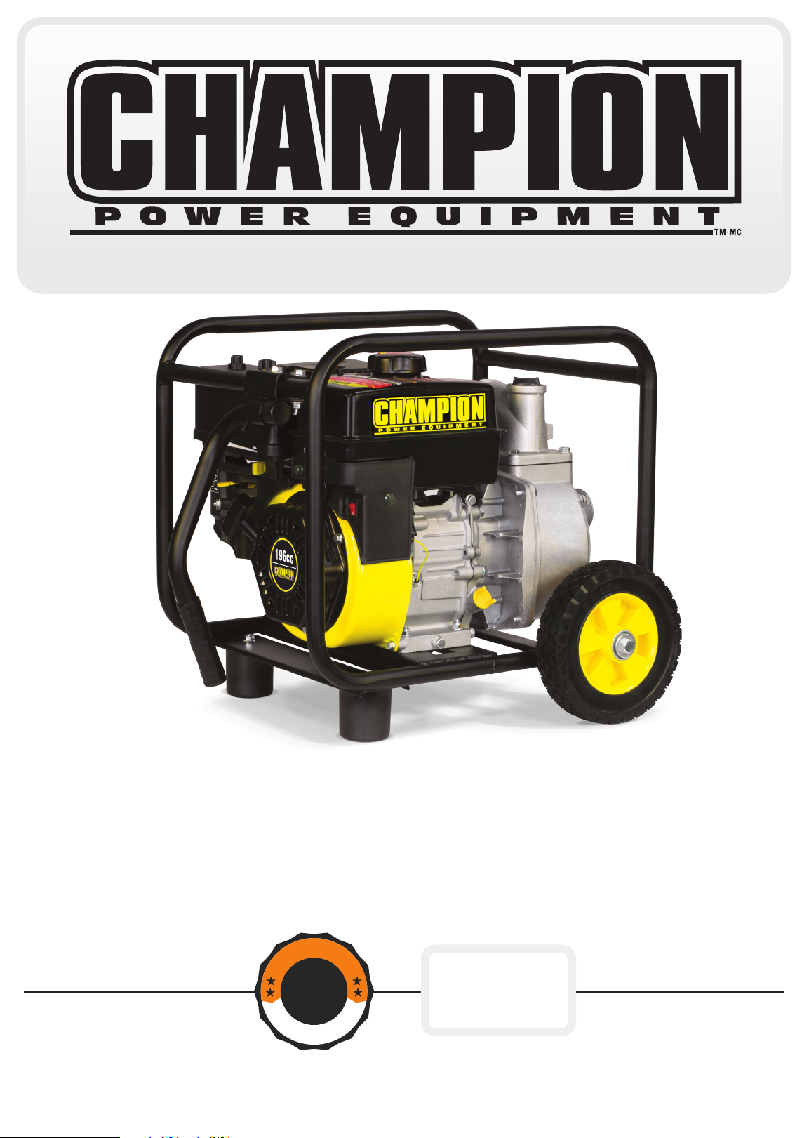
*We are always working to improve our products. Therefore, the enclosed product may differ slightly from the image on the cover.
Page 3
TABLE OF CONTENTS
100113
2 INCH SEMI-TRASH WATER TRANSFER
PUMP WITH HOSE KIT
Introduction ............................ 1
Manual Conventions ....................... 2
Safety Rules ............................ 3
Controls and Features ..................... 5
Semi-trash pump ...................... 5
Parts Included ........................ 6
Wheel Kit .......................... 6
Hose Kit .......................... 6
Other ............................ 6
Assembly .............................. 7
Remove the Semi-trash pump
from the Shipping Carton ................. 7
Install the Wheel Kit .................... 7
Install the Vibration Mounts ............... 7
Install the Handle ...................... 7
Add Engine Oil ........................ 8
Add Fuel ............................ 9
Operation ............................. 10
Semi-trash pump Location ............... 10
Connecting a Hose Kit .................. 10
Priming the Pump ..................... 11
Starting the Engine .................... 12
Stopping the Engine ................... 12
Operation at High Altitude ............... 13
Maintenance and Storage .................. 14
Engine Maintenance ................... 14
Oil ............................. 14
Spark Plugs ....................... 14
Air Filter ......................... 15
Cleaning ......................... 15
Adjustments ....................... 15
Maintenance Schedule ................ 15
Storage ............................ 16
Engine Storage ..................... 16
Semi-trash pump Storage .............. 16
Winter Storage ..................... 16
Troubleshooting ......................... 17
Specifications .......................... 18
Engine Specifications .................. 18
Semi-trash pump Specifications ........... 18
Fuel .............................. 18
Oil ............................... 18
Spark Plugs ......................... 18
Maintenance Valve Clearance ............. 18
An Important Message About Temperature .... 18
Parts Diagram ........................ 19
Parts List ........................... 20
Engine Parts Diagram .................. 21
Engine Parts List ..................... 22
Page 4

ENGLISH 100113
INTRODUCTION
Congratulations on your purchase of a Champion Power Equipment product. Champion Power Equipment and
Champion Engine Technology designs, builds, and supports all of our products to strict specifications and guidelines.
With proper product knowledge, safe use, and regular maintenance, this product should bring years of satisfying
service.
Every effort has been made to ensure the accuracy and completeness of the information in this manual, and we
reserve the right to change, alter and/or improve the product and this document at any time without prior notice.
Since CPE/CET highly value how our products are designed, manufactured, operated and are serviced, and also
highly value your safety and the safety of others, we would like you to take the time to review this product manual
and other product materials thoroughly and be fully aware and knowledgeable of the assembly, operation, dangers
and maintenance of the product before use. Fully familiarize yourself, and make sure others who plan on operating
the product fully familiarize themselves too, with the proper safety and operation procedures before each use. Please
always exercise common sense and always error on the side of caution when operating the product to ensure no
accidents, property damage, or injury occurs. We want you to continue to use and be satisfied with your CPE/CET
product for years to come.
Record the model and serial numbers as well as date and place of purchase for future reference. Have this
information available when ordering parts and when making technical or warranty inquiries.
Champion Power Equipment Support
1-877-338-0999
Model Number
100113
Serial Number
Date of Purchase
Purchase Location
For O il Ty pe see ‘Add Engine Oil‘ section. For Fue l Typ e see ‘Add Fuel‘ section.
1
Page 5
100113 ENGLISH
MANUAL CONVENTIONS
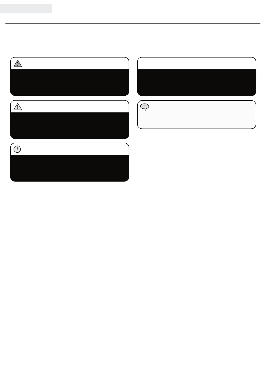
This manual uses the following symbols to help differentiate between different kinds of information. The safety symbol
is used with a key word to alert you to potential hazards in operating and owning power equipment.
Follow all safety messages to avoid or reduce the risk of serious injury or death.
DANGER
DANGER indicates an imminently hazardous
situation which, if not avoided, will result in death
or serious injury.
WARNING
WARNING indicates a potentially hazardous
situation which, if not avoided, could result in
death or serious injury.
CAUTION
CAUTION indicates a potentially hazardous
situation which, if not avoided, may result in minor
or moderate injury.
CAUTION
CAUTION used without the safety alert symbol
indicates a potentially hazardous situation which, if
not avoided, may result in property damage.
NOTE
If you have questions regarding your semi-trash pump,
we can help. Please call our help line at 1-877-338-0999
2
Page 6
SAFETY RULES
ENGLISH 100113
WARNING
Read this manual thoroughly before operating your
semi-trash pump. Failure to follow instructions
could result in property damage, serious injury or
death.
DANGER
DO NOT pump gasoline or fuel, fuel-oil mixtures,
detergents, acids, chemicals, beverages, pesticides,
fertilizers or any other flammable liquid or corrosive.
Pumping volatile liquids may result in an explosion
or fire. These liquids will corrode the pump and void
the warranty.
DANGER
Engine exhaust contains carbon monoxide, a
colorless, odorless, poison gas. Breathing carbon
monoxide will cause nausea, dizziness, fainting or
death. If you start to feel dizzy or weak, get to fresh
air immediately.
Operate semi-trash pump outdoors only in a
well ventilated area DO NOT operate the semitrash pump inside any building, enclosure or
compartment.
DO NOT allow exhaust fumes to enter a confined
area through windows, doors, vents or other openings.
DANGER
Rotating parts can entangle hands, feet, hair,
clothing and/or accessories.
Traumatic amputation or severe laceration can result.
Keep hands and feet away from rotating parts. Tie
up long hair and remove jewelry. Operate equipment
with guards in place. DO NOT wear loose-fitting
clothing, dangling drawstrings or items that could
become caught.
DANGER
The water pump develops powerful force.
DO NOT move the semi-trash pump when it is in
use. DO NOT use hoses or connectors that are
worn, damaged or frayed. DO NOT allow children or
unqualified persons to operate or service the semi-trash
pump. DO NOT open top plug or drain plug.
WARNING
Sparks can result in fire or electrical shock.
When servicing the semi-trash pump:
Disconnect the spark plug wire and place it where
it cannot contact the plug. DO NOT check for spark
with the plug removed. Use only approved spark
plug testers.
WARNING
DO NOT immerse this unit in water.
3
Page 7

100113 ENGLISH
SAFETY RULES
DANGER
Fuel and fuel vapors are highly flammable and
extremely explosive.
Fire or explosion can cause severe burns or death.
Unintentional startup can result in entanglement,
traumatic amputation or laceration.
When adding or removing fuel:
Turn the engine off and let it cool for at least two
minutes before removing the fuel cap. Loosen the
cap slowly to relieve pressure in the tank.
Only fill or drain fuel outdoors in a well-ventilated area.
DO NOT pump gas directly into the engine at the
gas station. Use an approved container to transfer
the fuel to the engine.
DO NOT overfill the fuel tank.
Always keep fuel away from sparks, open flames,
pilot lights, heat and other sources of ignition.
DO NOT light or smoke cigarettes.
When starting the engine:
DO NOT attempt to start a damaged engine. Make
certain that the gas cap, air filter, spark plug,
fuel lines and exhaust system are properly in
place. Allow spilled fuel to evaporate fully before
attempting to start the engine.
Make certain that the semi-trash pump is resting
firmly on level ground.
When operating the semi-trash pump:
DO NOT move or tip the semi-trash pump during
operation.
DO NOT tip the semi-trash pump or allow fuel or oil
to spill from the engine. Block the wheels to prevent
unintended movement.
When transporting or servicing the semi-trash
pump:
Make certain that the fuel shutoff valve is in the off
position and the fuel tank is empty.
Disconnect the spark plug wire.
When storing the semi-trash pump:
Store away from sparks, open flames, pilot lights,
heat and other sources of ignition.
WARNING
WARNING
DO NOT pump salt, sludge, sewer, sea, or any other
type of water containing solid material.
WARNING
Rapid retraction of the starter cord will pull hand and
arm towards the engine faster than you can let go.
Unintentional startup can result in entanglement,
traumatic amputation or laceration.
Broken bones, fractures, bruises or sprains could
result.
When starting engine, pull the starter cord slowly
until resistance is felt and then pull rapidly to avoid
kickback.
CAUTION
Exceeding the semi-trash pump’s specification for
maximum head can damage the semi-trash pump
and/or hose kits connected to it.
DO NOT modify the semi-trash pump in any
way. DO NOT attempt to exceed the rated flow.
Attempting to increase the rated flow may damage
the unit and/or shorten its life.
CAUTION
Improper treatment or use of the semi-trash pump
can damage it, shorten its life and void your warranty.
Use the semi-trash pump only for intended uses.
Operate only on level surfaces. DO NOT expose
semi-trash pump to excessive moisture, dust, or dirt.
DO NOT allow any material to block the cooling slots.
DO NOT use the semi-trash pump if:
– Equipment sparks, smokes or emits flames
– Equipment vibrates excessively
Water pumped through this unit shall not be used
as drinking water.
4
Page 8
ENGLISH 100113
CONTROLS AND FEATURES
Read this owner’s manual before operating your semi-trash pump. Familiarize yourself with the location and function
of the controls and features. Save this manual for future reference.
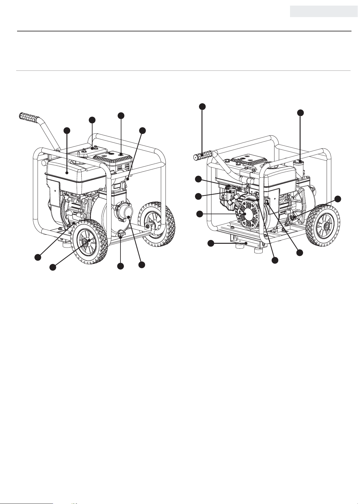
Semi-trash pump
9
2
5
6
3
41
10
11
12
13
7
8
14
17
16
15
(1) Fuel Tank – 0.9 gal. (3.4 L) capacity fuel tank.
(2) Air Filter – Protects the engine by filtering dust
and debris from the air intake.
(3) Muffler
(4) 2 in. (5.1 cm) Outlet – 2 in. (5.1 cm) NPT outlet
connector.
(5) Low Oil Sensor – Senses the level of oil in the
crankcase and shuts the engine down if the level
falls too low.
(6) 8 in. (20.3 cm) Never Flat Wheels
(7) Drain Plug
(8) 2 in. (5.1 cm) Inlet – 2 in. (5.1 cm) NPT inlet
connector.
(9) Handle
(10) Throttle Lever – Used to adjust engine speed.
(11) Choke lever– Used to start the engine.
(12) Recoil Starter – Used to start the engine.
(13) Support Leg with Anti-Vibration Mounts
(14) Fuel Valve – Used to turn fuel supply on and off to
engine.
(15) Engine Switch – Used to start the engine.
(16) Oil Filler Cap – Check and fill engine oil level.
(17) Priming Plug – Remove plug to prime pump.
Replace plug before starting pump.
5
Page 9
100113 ENGLISH
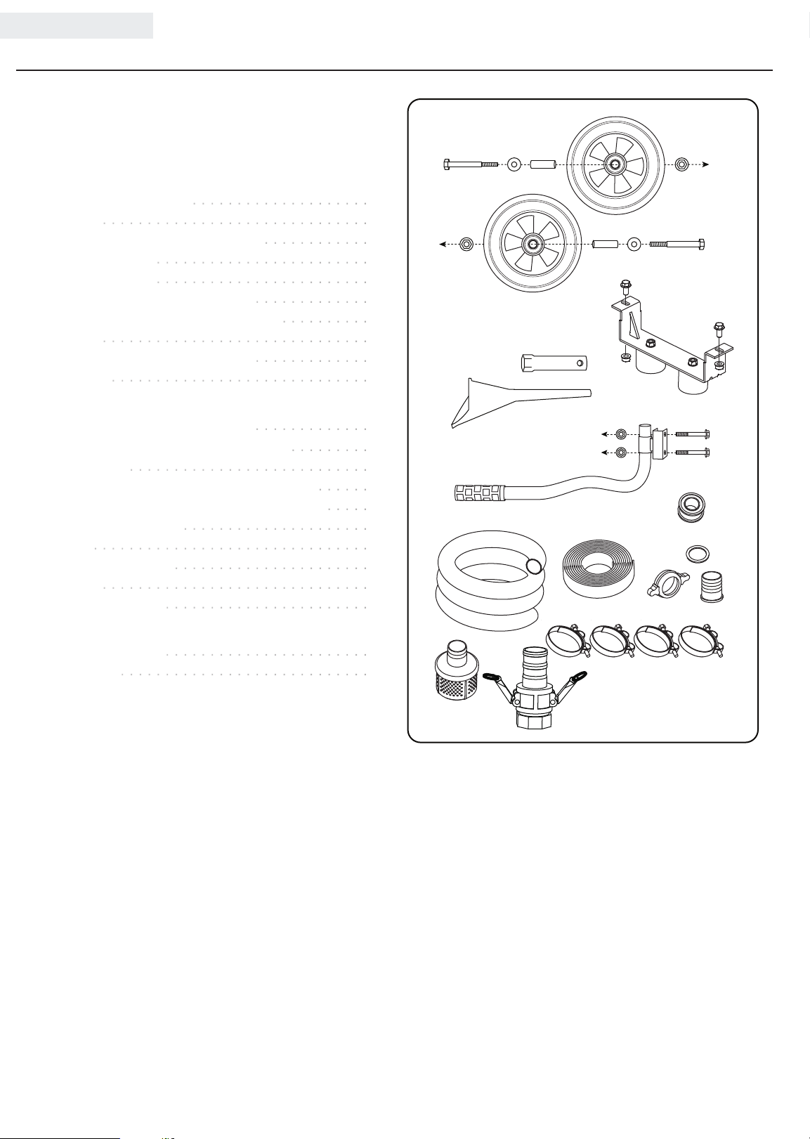
Parts Included
Your model 100113 gasoline powered semi-trash pump
ships with the following parts:
Wheel Kit
– 8 in. (20.3 cm) Wheel ....................2
– Bushing ..............................2
– Flange Bolt (M10x105 for Wheel) ............2
– Flat Washer ø10 ........................2
– Lock Nut (M10) ........................2
– Support Leg w/Vibration Mounts .............1
– Flange Bolt (M8x16 for Support Leg) ..........2
– Handle ..............................1
– Flange Bolt (M8x45 for Handle) .............2
– Nut (M8) .............................4
Hose Kit
– 12 ft. (3.7 m) Rigid Intake Hose .............1
– 20 ft. (6.1 m) Collapsible Outlet Hose .........1
– Teflon Tape ...........................1
– Clamp, 22 × 54-57 mm, Inlet, Gold Color ......3
– Clamp, 22 × 52-55 mm, Outlet, Silver Color ..... 1
– Outlet Hose Adapter .....................1
– Gasket ............................... 1
– Outlet Hose Fitting ......................1
– Strainer ..............................1
– Cam Lock Coupler ....................... 1
CONTROLS AND FEATURES
Other
– Spark Plug Socket ....................... 1
– Oil Funnel ............................1
6
Page 10
ASSEMBLY
ENGLISH 100113
Your semi-trash pump requires some assembly. This unit
ships from our factory without oil. It must be properly
serviced with fuel and oil before operation.
If you have any questions regarding the assembly of your
semi-trash pump, call our help line at 1-877-338-0999.
Please have your serial number and model number
available.
Remove the Semi-trash pump from the Shipping Carton
1. Set the shipping carton on a solid, flat surface.
2. Remove everything from the carton except the
semi-trash pump.
3. Carefully cut each corner of the box from top to bottom.
Fold each side flat on the ground to provide a surface
area to install the wheel kit and support leg.
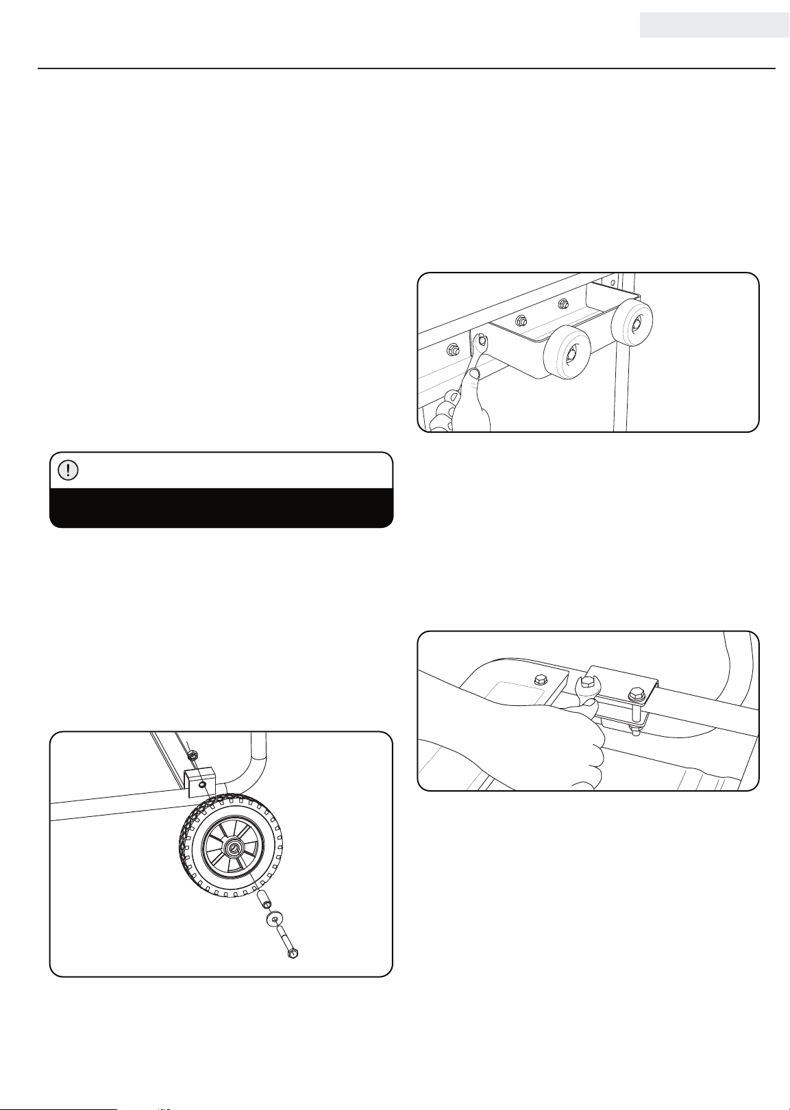
Install the Wheel Kit
CAUTION
The wheel kit is not intended for over-the-road use.
You will need the following tools to install the wheels:
• 17 mm wrench OR adjustable wrench (not included)
• Socket wrench with a 16 mm socket (not included)
1. Slide the M10x105 wheel bolt through the washer,
sleeve and wheel.
2. Slide the bolt through the mount point on the frame.
3. Fasten securely with the M10 nut.
4. Repeat steps 1-3 to attach the second wheel.
Install the Vibration Mounts
1. Attach the support leg with rubber vibration mounts
to the frame cross member using a flange bolt
(M8x16) and nut (M8).
2. Thread the flange bolt through the vibration mount
and the frame.
3. Secure with nut. Tighten, but DO NOT over tighten.
4. Repeat steps 1-3 for second other side of the leg.
Install the Handle
1. Place the handle over the mounting channel on the
frame.
2. Secure the handle to the frame using the two handle
bolts (M8x45).
3. Place a nut (M8) on the end of each bolt and fasten
securely. DO NOT over tighten the lock nuts.
7
Page 11
100113 ENGLISH
ASSEMBLY
Add Engine Oil
CAUTION
DO NOT attempt to crank or start the engine before
it has been properly filled with the recommended
type and amount of oil. Damage to the generator as
a result of failure to follow these instructions will
void your warranty.
NOTE
The generator rotor has a sealed, pre-lubricated ball
bearing that requires no additional lubrication for
the life of the bearing.
NOTE
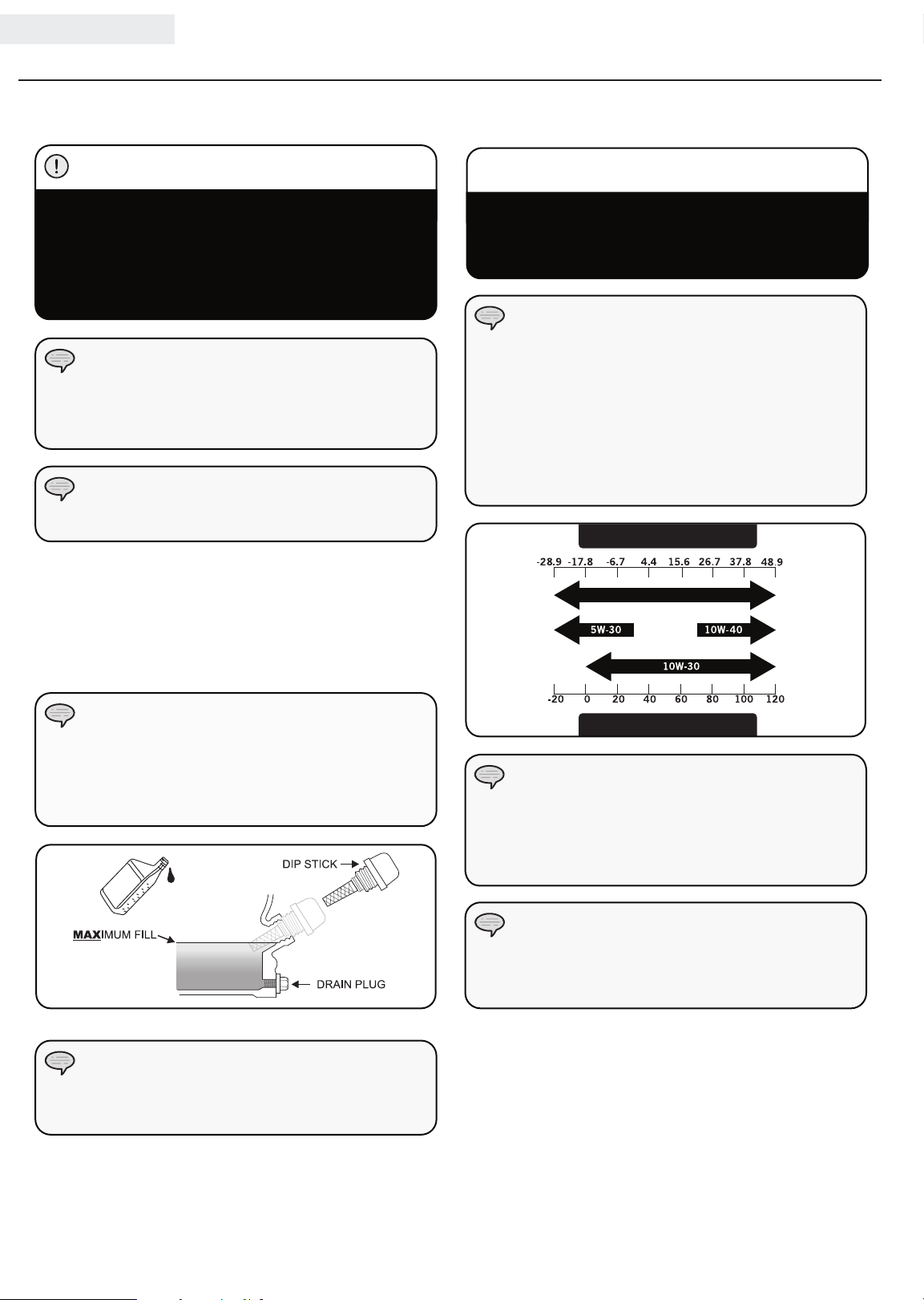
The recommended oil type is 10W-30 automotive oil.
1. Place the generator on a flat, level surface.
2. Remove oil fill cap/dipstick to add oil.
3. Add up to 0.6 qt. (0.6 L) of oil (not included) and
replace oil fill cap/dipstick. DO NOT OVERFILL.
4. Check engine oil level daily and add as needed.
Add Engine Oil Cont’d.
CAUTION
The engine is equipped with a low oil shut-off and
will stop when the oil level in the crankcase falls
below the threshold level.
NOTE
We consider the first 5 hours of run time to be
the break-in period for the unit. During the break
in period stay at or below 50% of the running
watt rating and vary the load occasionally to allow
stator windings to heat and cool. Adjusting the
load will also cause engine speed to vary and help
seat piston rings. After the 5 hour break-in period,
change the oil.
Degrees Celsiusº
Full Synthetic 5W-30
(Outside)
NOTE
Once oil has been added, a visual check should show
oil about 1-2 threads from running out of the fill hole.
If using the dipstick to check oil level, DO NOT screw
in the dipstick while checking.
NOTE
Check oil often during the break-in period. Refer to the
Maintenance section for recommended service intervals.
Degrees Fahrenheitº
(Outside)
NOTE
Weather will affect engine oil and engine
performance. Change the type of engine oil used
based on weather conditions to suit the engine
needs.
NOTE
Synthetic oil may be used after the 5 hour initial
break-in period. Using synthetic oil does not
increase the recommended oil change interval.
8
Page 12
ASSEMBLY
ENGLISH 100113
Add Fuel
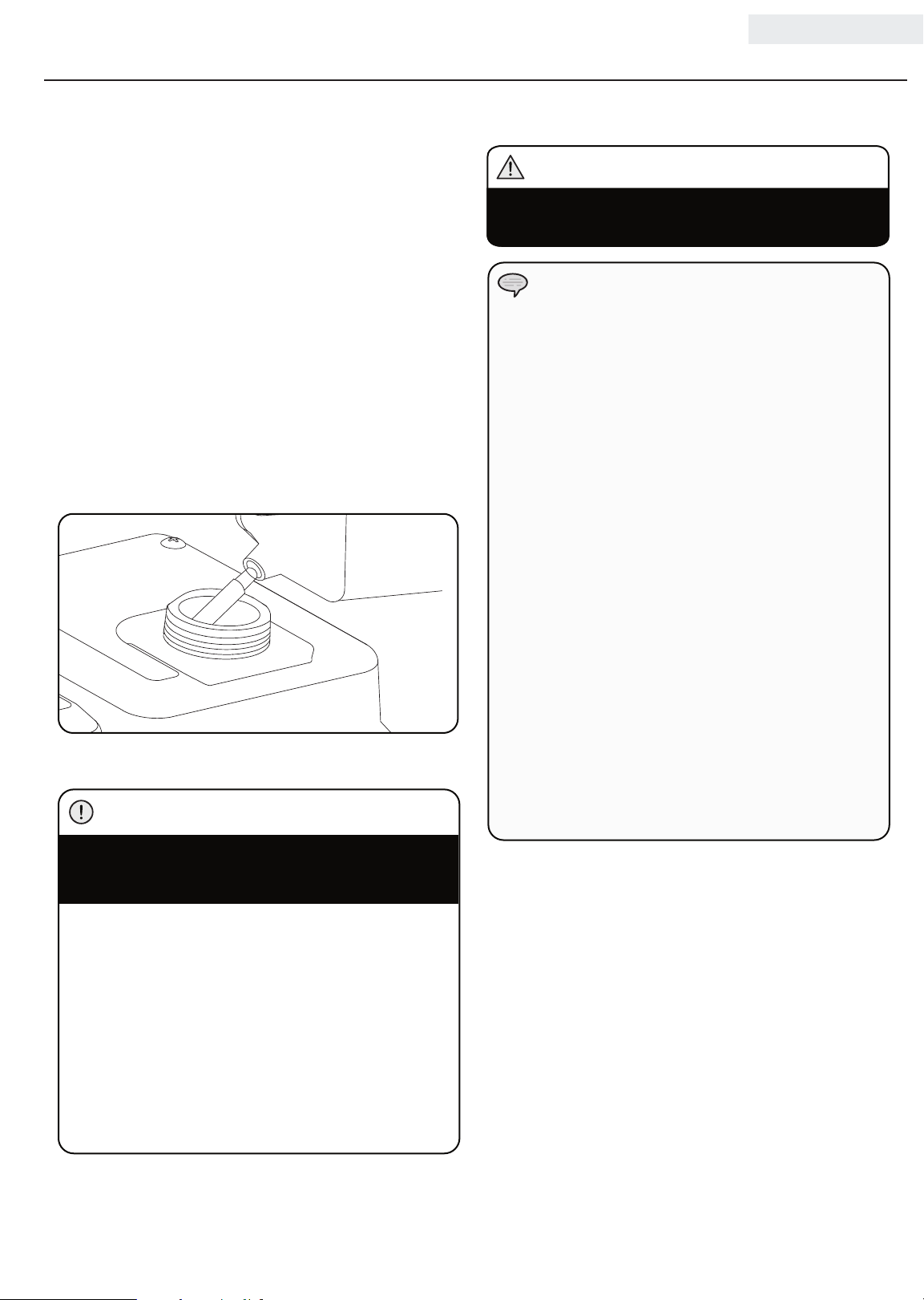
1. Use clean, fresh, regular unleaded fuel with a
minimum octane rating of 87 and an ethanol
content of less than 10% by volume.
2. DO NOT mix oil with fuel.
3. Clean the area around the fuel cap.
4. Remove the fuel cap.
5. Slowly add fuel to the tank. DO NOT OVERFILL. Fuel
can expand after filling. A minimum of 6.4 mm (¼ in.)
of space left in the tank is required for fuel expansion,
more than 6.4 mm (¼ in.) is recommended. Fuel
can be forced out of the tank as a result of expansion
if it is overfilled, and can affect the stable running
condition of the product. When filling the tank, it is
recommended to leave enough space for the fuel to
expand.
6. Screw on the fuel cap and wipe away any spilled fuel.
CAUTION
Add Fuel Cont’d.
WARNING
Pouring fuel too fast through the fuel screen may
result in blow back of fuel at the operator while filling.
NOTE
Our engines work well with 10% or less ethanol
blend fuels. When using blended fuels there are
some issues worth noting:
– Ethanol-gasoline blends can absorb more water
than gasoline alone.
– These blends can eventually separate, leaving
water or a watery goo in the tank, fuel valve and
car bureto r.
– With gravity-fed fuel supplies, this compromised
fuel can be drawn into the carburetor and cause
damage to the engine and/or potential hazards.
– There are only a few suppliers of fuel stabilizer
that are formulated to work with ethanol blend
fuels.
– Any damages or hazards caused by using
improper fuel, improperly stored fuel, and/
or improperly formulated stabilizers, are not
covered by manufacture’s warranty.
It is advisable to always shut off the fuel supply,
run the engine to fuel starvation and drain the tank
when the equipment is not in use for more than 30
days.
Use regular unleaded gasoline with a minimum
octane rating of 87.
Do not mix oil and gasoline.
Fill tank to approximately 6.4 mm (¼ in.) below the
top of the tank to allow for fuel expansion.
DO NOT pump gas directly into the generator at the
gas station. Use an approved container to transfer
the fuel to the generator.
DO NOT fill fuel tank indoors.
DO NOT fill fuel tank when the engine is running or hot.
DO NOT overfill the fuel tank.
DO NOT light cigarettes or smoke when filling the
fuel tank.
9
Page 13
100113 ENGLISH
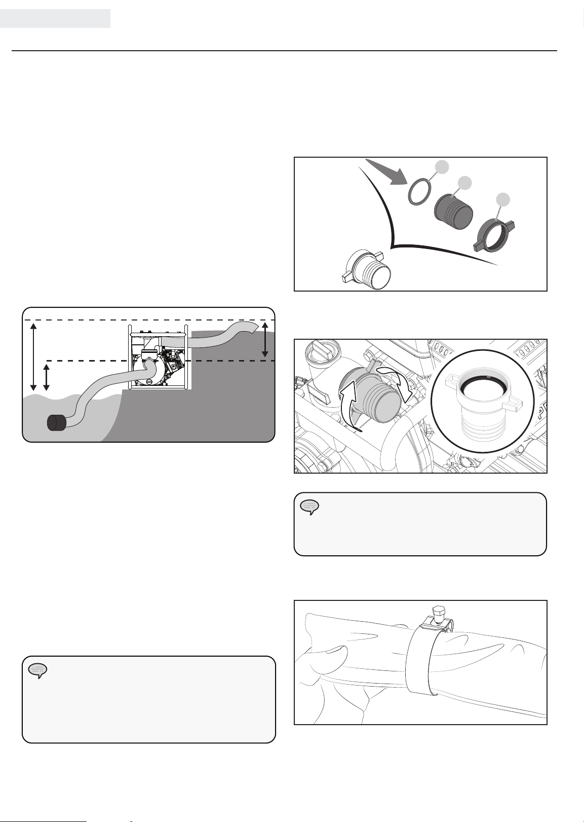
TOTAL HEAD
DISCHARGE HEAD
SUCTION HEAD
OPERATION
Semi-trash pump Location
Place the semi-trash pump in a well ventilated area. DO
NOT place the semi-trash pump near vents or intakes
where exhaust fumes could be drawn into occupied
or confined spaces. Carefully consider wind and air
currents when positioning semi-trash pump.
This semi-trash pump must have at least 5 ft. (1.5 m) of
clearance from combustible material. Leave at least
3 ft. (91.4 cm) of clearance on all sides of the semitrash pump to allow for adequate cooling, maintenance
and servicing.
Place the pump on a level surface free from any
obstructions or potential hazards. The pump should
be placed close to the water level to ensure maximum
pump performance.
Connecting a Host Kit Cont’d.
Connect the Discharge Hose (Blue)
1. Locate (1) of the following: outlet hose adapter (C),
gasket (A), and outlet hose fitting (B) and align for
assembly.
A
B
C
2. Thread the assembled connector to the outlet fitting
(top of pump).
Pump output will be affected by the type, length, and
size of the suction and discharge hoses. The pumping
height, also known as the total head, is the distance
from the water level to the point of discharge. As
this distance increases, pump output decreases. The
discharge capacity is greater than the suction capacity.
Therefore, it is important that the suction head is less
than the discharge head.
The time required to draw water from the source to
the pump (self-priming time) can be decreased by
minimizing the suction head.
Connecting a Hose Kit
NOTE
Both the intake and discharge ports are 2 in.
(5.1 cm) NPT. Please insure the connectors to the
suction and discharge hose are 2 in. (5.1 cm) NPT
threaded.
NOTICE
Make sure the gasket is seated inside before
threading the adapter on.
3. Locate and slide the silver colored hose clamp
(marked 52-55) over the blue outlet hose.
10
Page 14
OPERATION
Connecting a Hose Kit Cont’d. Connecting a Hose Kit Cont’d.
ENGLISH 100113
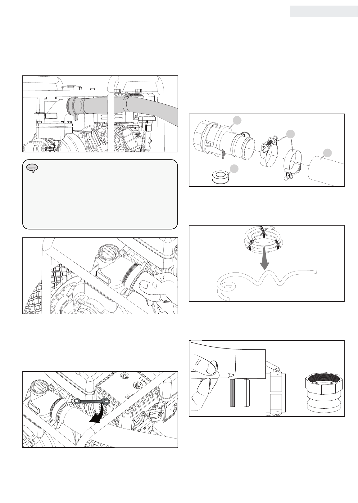
4. Slide the blue discharge hose over the outlet hose
fitting.
NOTICE
You may use a small amount of dish soap on the
outlet hose fitting to help ease the outlet hose on
the fitting. Work the soap around the fitting with
your finger. Then work the blue hose on the outlet,
by twisting and turning until it’s fully seated.
Connect the Suction Hose (Green) and Suction
Filter
1. Locate the following: cam lock coupler (coupler and
fitting together) (A), 54-57 marked hose clamps (B),
Teflon® tape (C), green suction hose (D) and align
for assembly.
A
B
D
C
2. Cut ties and uncoil the green hose and use some
weight to help straighten the hose out. Best to do
this on a warmer day in the sun.
5. Slide the hose clamp in place about midway on the
outlet hose adapter as shown. Tighten to 7.4±1.5
lbf-ft (10±2 Nm) with a 10mm wrench. The hose
clamp should be placed behind the outlet adapter
barbs on the smooth part of the adapter.
11
3. Separate the cam lock coupler and fitting. Align the
green hose to the coupler and mark the locations of
the ribs on the fitting.
Page 15
100113 ENGLISH
Connecting a Hose Kit Cont’d. Connecting a Hose Kit Cont’d.
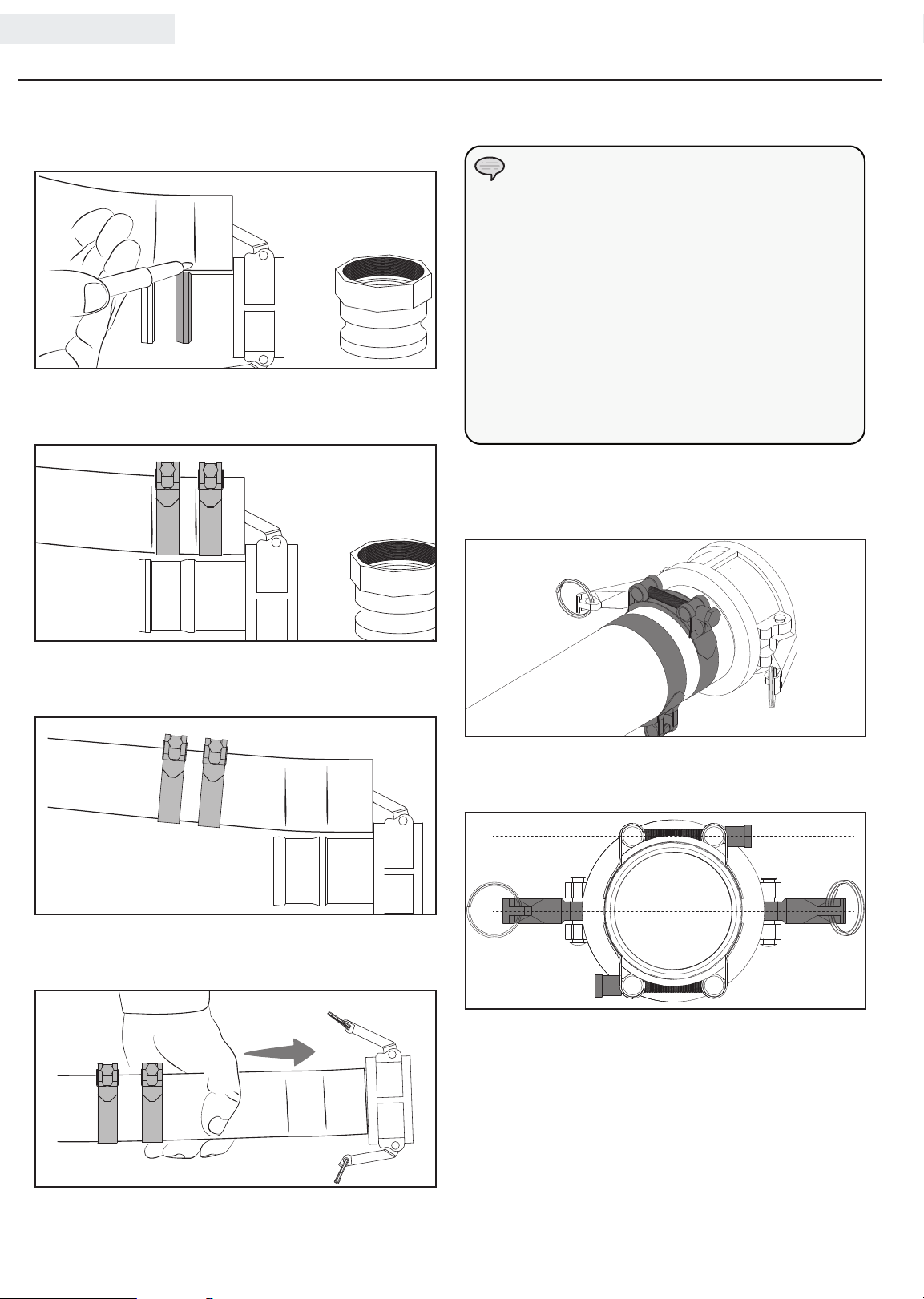
4. Mark the second rib on the coupler on the hose.
NOTICE
You may use a small amount of dish soap on the
cam lock coupler to help ease the green hose on
the fitting. Work the soap around the coupler with
your finger. Then work the green hose on the fitting,
by twisting and turning until it’s fully seated.
You may need to dip the green suction hose into
boiling water for 1 minute to install the hose as
well. This will allow the material to stretch some
5. Lay the green hose side by side and place the clamp
marked 54-57 in their approximate location.
while assembling the green hose to the cam lock
co upler.
8. Slide the clamps marked 54-57 over cam lock
coupler just past the marks you made on the hose
earlier.
OPERATION
6. Slide the clamps back and start to assemble the
green hose to cam lock coupler.
7. Insert the cam lock coupler in the green rigid
suction hose until properly seated.
9. Rotate and align the clamp bolts so you have
clearance for the cam levers to lock in place later.
12
Page 16
OPERATION
Connecting a Hose Kit Cont’d. Connecting a Hose Kit Cont’d.
ENGLISH 100113
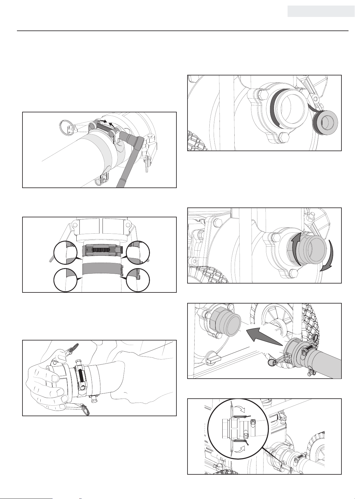
10. Tighten each clamp to 11.1±1.5 lbf-ft (15±2 Nm)
with a 10mm socket and 3/8” drive ratchet until
the clamp completely tightens. If you do not have
a torque wrench, hand tight then ¼ turn past full
tight. This will need to be as tight as you can make
them.
11. Once tightened, visually confirm the hose is raised
on the ribs. This indicates you have it tight.
13. Wrap the green inlet clockwise with the Teflon® tape
provided with 4 complete wraps.
14. Thread the fitting over the tape and hand tighten.
Use either 14” Channellock® or a pipe wrench with
2.5” (63.5mm) opening min, hand tight then 1 1/2
turn past full tight. This is critical to make sure the
fitting is tight so you do not have air leaks.
12. Test connection is tight by twisting coupler in the
hose to make sure it doesn’t turn. If coupling turns,
then tighten clamps further until coupling won’t
turn.
15. Attach the cam lock coupler to the fitting.
16. Lock in place with the cam levers.
13
Page 17
100113 ENGLISH
OPERATION
Connecting a Hose Kit Cont’d.
NOTICE
If the cam levers do not clamp down completely,
rotate and align the clamp bolts so you have
clearance for the cam levers to lock. See step 9
earlier.
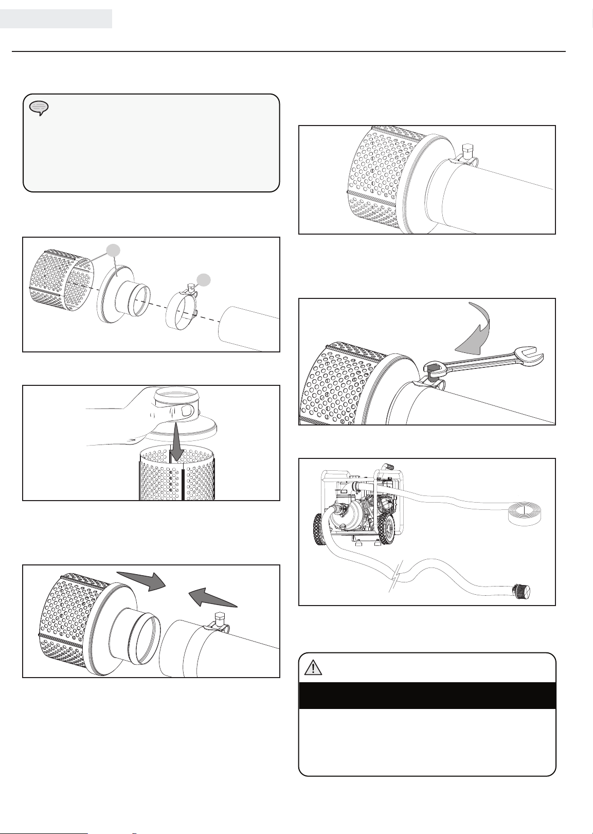
17. Locate the following: filter (E) and 54-57 marked
hose clamp (F).
E
F
18. Snap the filter pieces together.
Connecting a Hose Kit Cont’d.
20. Slide the clamp just before the end of the green
hose.
21. Tighten the clamp to 7.4±1.5 lbf-ft (10±2 Nm)
with a 10mm wrench. If you do not have a torque
wrench, hand tight then ¼ turn past full tight.
19. Place the clamp marked 54-57 on the other end
of the green hose. Attach the strainer to the green
suction hose.
22. You should have everything connected.
Priming the Pump
WARNING
DO NOT run the pump dry.
Running the pump dry can destroy the pump seals
and will void the warranty. If the pump was running
while dry, stop the engine and allow it to cool
thoroughly before filling the chamber with water.
14
Page 18

OPERATION
Priming the Pump Cont’d. Starting the Engine Cont’d.
Located on the outlet flange is the priming plug.
Remove the priming plug and fill pump body to the very
top of outlet flange with water. Reinstall the priming
plug. As the engine starts up, this will start the draw of
liquid into the pump. Located within the pump assembly
is the one-way valve. As you prime the pump housing
this one-way flap valve shuts off the opening to the
suction hose. The priming process is only required when
the pump housing is not full of water.
NOTE
If the engine starts but does not run make certain
that the semi-trash pump is on a flat, level surface.
The engine is equipped with a low oil sensor that
will prevent the engine from running when the oil
level falls below a critical threshold.
NOTE
Keep choke lever in “Choke” position for 2 pulls of
the recoil starter. After 2 pulls, move choke lever to
the “Run” position for up to the next 3 pulls of the
recoil starter. Too much choke leads to spark plug
fouling/engine flooding due to the lack of incoming
air. This will cause the engine not to start.
ENGLISH 100113
NOTE
Ensure the priming plug is secure before pump
operation, if not secure the priming plug could be
ejected and water or other liquids could be pumped
through the top of the outlet flange.
Starting the Engine
1. Make certain the semi-trash pump is on a flat, level
surface.
2. Flip engine switch (A) to “ON” position.
3. Rotate the fuel valve (B) to the “ON” position.
4. Move the choke lever (C) to the “Choke” position.
5. Move throttle lever to middle position. (D)
6. Pull the starter cord slowly until resistance is felt
and then pull rapidly.
7. As engine warms up, move the choke lever (C) to
“ R u n ”.
8. Move the throttle lever (D) to the “Fast” position.
B
NOTE
Pump performance can be adjusted using the
throttle. To decrease pump output, slide the throttle
to the right. To increase it, slide the throttle to the
left.
WARNING
DO NOT remove either top, or drain (bottom) plugs
while the water pump is on and running
Loss of pressure and suction will occur. Injury may
also occur.
Stopping the Engine
1. Turn the fuel valve to the “OFF” position.
2. Let the engine run until fuel starvation has stopped
the engine. This usually takes a few minutes.
3. Move the throttle lever to slow position.
4. Press the engine switch to the “OFF” position.
Important: Always ensure that the Fuel Valve and the
Engine Switch are in the “OFF” position when the engine
is not in use.
15
D
A
C
NOTE
If the engine will not be used for a period of two (2)
weeks or longer, please see the Storage section for
proper engine and fuel storage.
Page 19
100113 ENGLISH
Operation at High Altitude
The density of air at high altitude is lower than at sea
level. Engine power is reduced as the air mass and airfuel ratio decrease. Engine power and generator output
will be reduced approximately 3½% for every 1000
feet of elevation above sea level. This is a natural trend
and cannot be changed by adjusting the engine. At high
altitudes increased exhaust emissions can also result
due to the increased enrichment of the air fuel ratio.
Other high altitude issues can include hard starting,
increased fuel consumption and spark plug fouling.
To alleviate high altitude issues other than the natural
power loss, Champion Power Equipment can provide a
high altitude carburetor main jet. The alternative main
jet and installation instructions can be obtained by
contacting Customer Support. Installation instructions
are also available in the Technical Bulletin area of the
Champion Power Equipment internet site.
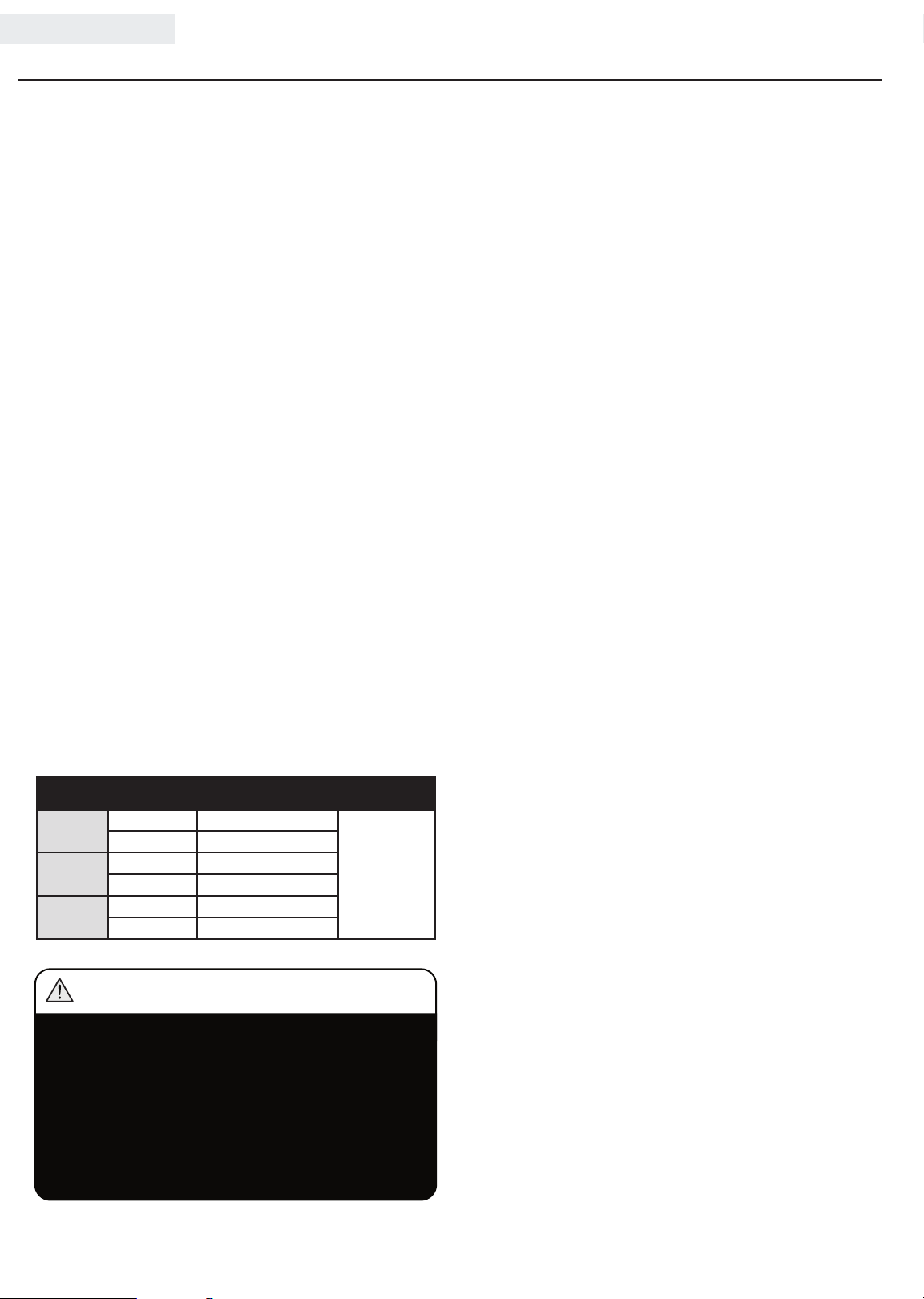
The part number and recommended minimum altitude
for the application of the high altitude carburetor main
jet is listed in the table below.
In order to select the correct high altitude main jet
it is necessary to identify the carburetor model. For
this purpose, a code is stamped on the side of the
carburetor. Select the correct main jet part number
corresponding to the carburetor code found on your
particular carburetor.
OPERATION
Carburetor
Code
P19 -1- H
P19 -1- Z
P19 -1-Y
Main Jet Part Number Altitude
Standard 26.1 310 17.0 0 . H
Altitude 26.131017.00.01.H
Standard 26.1 310 17.0 0 . Z
Altitude 26.1 310 17.0 0 .01. Z
Standard 26.1 310 17.0 0 .Y
Altitude 26.131017.00.01.Y
3500 Feet
(1067 Meters)
WARNING
Operation using the alternative main jet at
elevations lower than the recommended minimum
altitude can damage the engine. For operation at
lower elevations, the standard main jet must be
used. Operating the engine with the wrong engine
configuration at a given altitude may increase
its emissions and decrease fuel efficiency and
performance.
16
Page 20
MAINTENANCE AND STORAGE
ENGLISH 100113
The owner/operator is responsible for all periodic
maintenance.
WARNING
Never operate a damaged or defective semi-trash pump.
WARNING
Tampering with the factory set governor will void
your warranty.
WARNING
Improper maintenance will void your warranty.
NOTE
Maintenance, replacement, or repair of emission
control devices and systems may be performed
by any non-road engine repair establishment or
individual.
Complete all scheduled maintenance in a timely manner.
Correct any issue before operating the semi-trash pump.
NOTE
For service or parts assistance, contact our help
line at 1-877-338-0999.
Engine Maintenance
To prevent accidental starting, remove and ground spark
plug wire before performing any service.
Oil
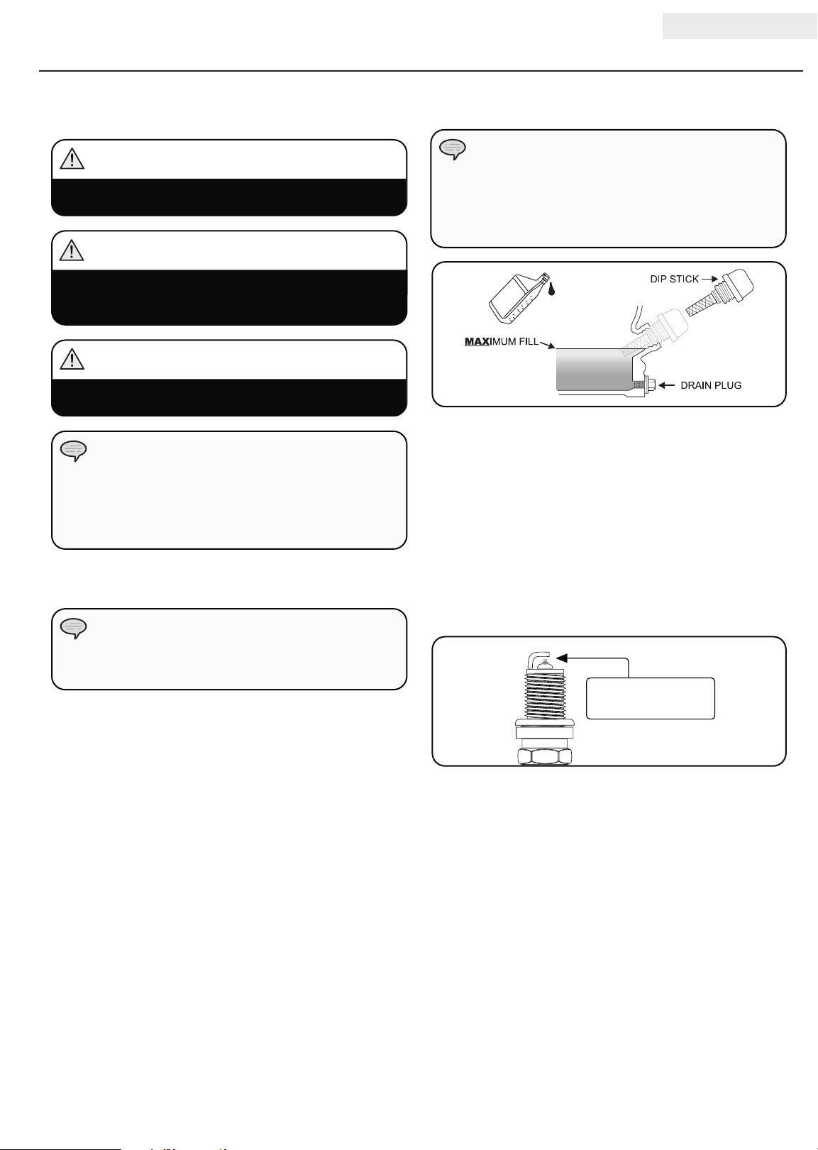
Change oil when the engine is warm. Refer to the oil
specification to select the proper grade of oil for your
operating environment.
1. Remove the oil drain plug with a 12 mm socket and
extension (not included).
2. Allow the oil to drain completely.
3. Replace the drain plug.
4. Remove oil fill cap/dipstick to add oil.
5. Add up to 0.6 qt. (0.6 L) of oil and replace oil fill
cap/dipstick. DO NOT OVERFILL.
6. Dispose of used oil at an approved waste
management facility.
Oil Cont’d.
NOTE
Once oil has been added, a visual check should show
oil about 1-2 threads from running out of the fill hole.
If using the dipstick to check oil level, DO NOT screw
in the dipstick while checking.
Spark Plugs
1. Remove the spark plug cable from the spark plug.
2. Use the spark plug tool that shipped with your semitrash pump to remove the plug.
3. Inspect the electrode on the plug. It must be clean
and not worn to produce the spark required for
ignition.
4. Make certain the spark plug gap is 0.7 - 0.8 mm or
(0.028 - 0.031 in.).
0.7 - 0.8 mm
0.028 - 0.031 in.
5. Refer to spark plug section on specifications page.
6. Carefully thread the plug into the engine.
7. Use the spark plug tool to firmly install the plug.
8. Attach the spark plug wire to the plug.
17
Page 21
100113 ENGLISH
MAINTENANCE AND STORAGE
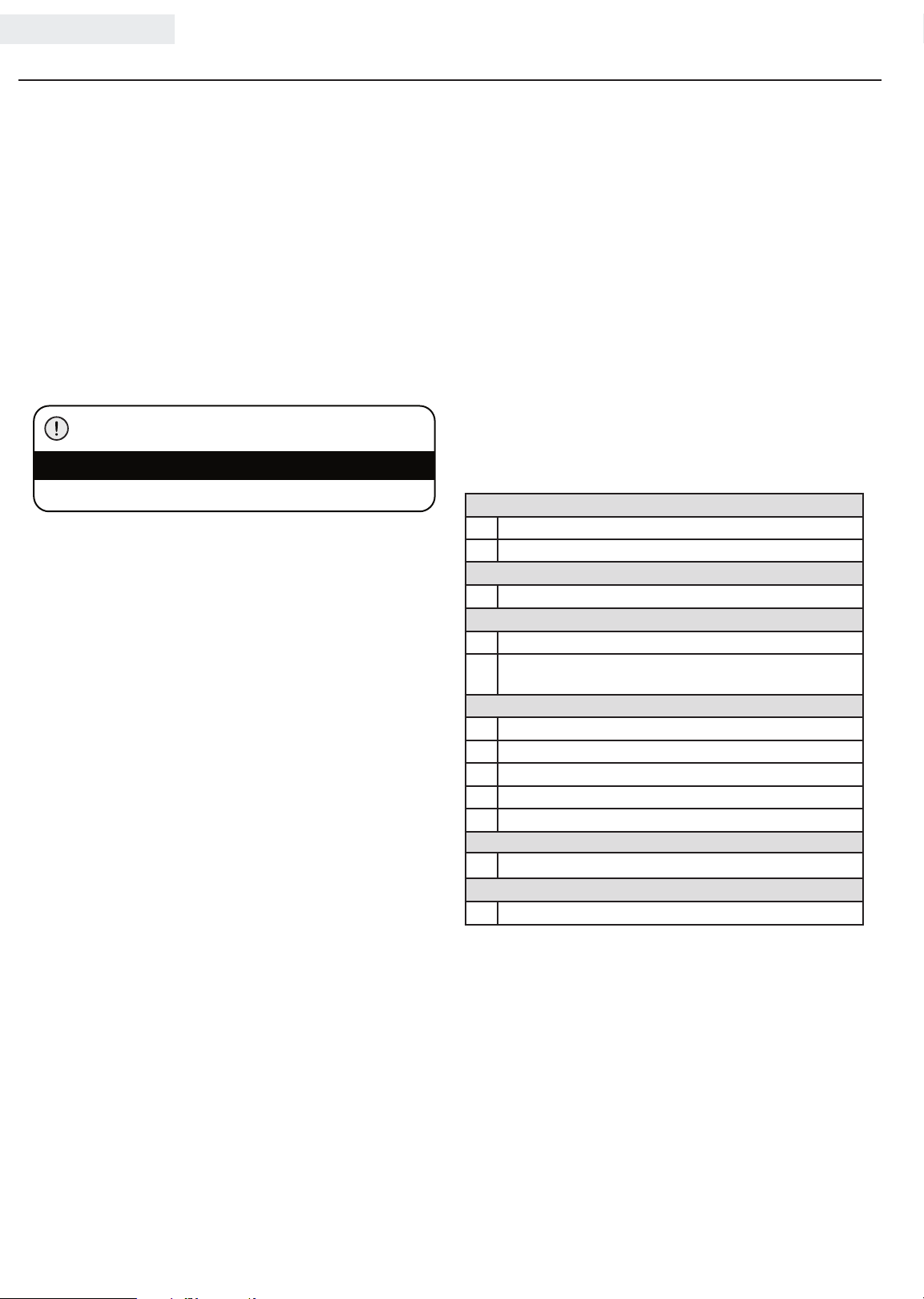
Air Filter
1. Unscrew wing nut to remove the air filter cover.
2. Remove the foam element.
3. Wash in liquid detergent and water. Squeeze
thoroughly dry in a clean cloth.
4. Saturate in clean engine oil.
5. Squeeze in a clean, absorbent cloth to remove all
excess oil.
6. Reassemble the element.
7. Reattach the air filter cover and tighten wing nut.
Cleaning
CAUTION
DO NOT spray engine with water.
Water can contaminate the fuel system.
Use a damp cloth to clean exterior surfaces of the
engine.
Use a soft bristle brush to remove dirt and oil.
Use an air compressor (25 PSI) to clear dirt and debris
from the engine.
Adjustments
The air-fuel mixture is not adjustable. Tampering with
the governor can damage your semi-trash pump and your
electrical devices and will void your warranty.
CPE recommends that you contact our service line at
1-877-338-0999 for all other service and/or adjustment
needs.
Maintenance Schedule
Follow the service intervals indicated in the following
maintenance schedule.
Service your semi-trash pump more frequently when
operating in adverse conditions.
Contact our help line at 1-877-338-09 9 9 to locate the
nearest Champion Power Equipment certified service dealer
for your semi-trash pump or engine maintenance needs.
Every 8 hours or daily
Check oil level
Clean around air intake and muffler
First 5 Hours
Change oil
Every 50 hours or every season
Clean air filter
Change oil if operating under heavy load or in hot
environments
Every 100 hours or every season
Change oil
Clean/Adjust spark plug
Check/Adjust valve clearance*
Clean spark arrester
Clean fuel tank and filter*
Every 250 hours
Clean combustion chamber*
Every 3 years
Replace fuel line
*To be performed by knowledgeable, experienced owners or
Champion Power Equipment certified dealers.
18
Page 22
MAINTENANCE AND STORAGE
ENGLISH 100113
Storage
For longer term storage, please follow these guidelines.
Engine Storage
1. Allow the engine to cool completely before storage.
2. Clean the engine according to the instructions in the
Maintenance section.
3. Drain all fuel completely from the fuel line and
carburetor to prevent gum from forming.
4. Add a fuel stabilizer into the fuel tank.
5. Change the oil.
6. Remove the spark plug and pour about ½ ounce
(14.8 ml) of oil into the cylinder. Crank the engine
slowly to distribute the oil and lubricate the cylinder.
7. Reattach the spark plug.
Semi-trash pump Storage
1. Allow the semi-trash pump to cool completely before
storage.
2. Turn off the fuel supply at the fuel valve.
3. Drain the pump chamber thoroughly.
4. Clean the semi-trash pump according to the
instructions in the Maintenance section.
5. Once the pump is dry, spray WD-40 or similar
product into the pump housing through all ports and
drainage hole.
6. Store in a clean, dry place out of direct sunlight.
Winter Storage
Protect your semi-trash pump parts from freezing.
1. Apply all storage instructions from previous sections.
2. Make sure semi-trash pump hose is free of all water
before storing for winter.
3. In order to prevent the pump from freezing you will
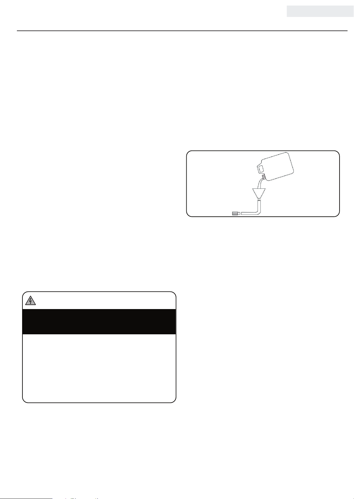
need to insert RV antifreeze.
4. You will need approximately 6 ounces (177.4 ml) of
RV Antifreeze, a funnel, and approximately 12 in.
(30.5 cm) of garden hose or equivalent. See diagram
below.
5. Pour the antifreeze into the funnel, then pull on the
engine recoil starter to create suction in the pump
housing. Pull the recoil several times until antifreeze
comes out of the pump outlet. DO NOT START THE
ENGINE WHEN DO THIS. Only pull the recoil cord
if the fuel valve and engine switch are in the OFF
position.
DANGER
Generator exhaust contains odorless and colorless
carbon monoxide gas.
To avoid accidental or unintended ignition of your
generator during periods of storage, the following
precautions should be followed:
– When storing the generator for short or extended
periods of time make sure that the Engine
Switch and the Fuel Valve are set in the OFF
position.
19
Page 23
100113 ENGLISH
SPECIFICATIONS
Engine Specifications
– Model ......................YF168F-2-000
– Displacement .......................196cc
– Typ e ........................4-Stroke OHV
– Start Type .........................Recoil
Semi-trash pump Specifications
– Model ...........................100113
– Inlet Diameter ..............2 in. (5.1 cm) NPT
– Outlet Diameter ............2 in. (5.1 cm) NPT
– Fuel Capacity ................ 0.9 gal. (3.4 L)
– Total Head .................. 98 ft. (29.9 m)
– Suction Head ..................26 ft. (7.9 m)
– Max Delivery Volume .....158 gal/min (598 L/min)
– Max Solid Waste .......9/16 in. diameter (1.4 cm)
– Gross Weight .............. 84.9 lb. (38.5 kg)
– Net Weight ..................66.1 lb. (30 kg)
– Height ................... 19.2 in. (48.8 cm)
– Width ...................20.8 in. (52.8 cm)
– Length. . . . . . . . . . . . . . . . . . . . 25 in. (63.6 cm)
Fuel
Fuel capacity is 0.9 gal. (3.4 L). Use regular unleaded
gasoline with a minimum octane rating of 87 and an
ethanol content of no more than 10% by volume.
Spark Plugs
OEM spark plug: NHSP F6RTC
Replacement spark plug: NGK BPR6ES or equivalent
Make certain the spark plug gap is 0.7 - 0.8 mm or
(0.028 - 0.031 in.).
Maintenance Valve Clearance
– Intake: 0.13 – 0.17 mm (0.005 – 0.007 in.)
– Exhaust: 0.18 – 0.22 mm (0.007 – 0.009 in.)
Note: Tech bulletin regarding the valve adjustment
procedure is on www.championpowerequipment.com.
An Important Message About Temperature
Your Champion Power Equipment product is designed
and rated for continuous operation at ambient
temperatures up to 40°C (104°F). When your product is
needed your product may be operated at temperatures
ranging from -15°C (5°F) to 50°C (122°F) for short
periods. If the product is exposed to temperatures
outside this range during storage, it should be brought
back within this range before operation. In any event,
the product must always be operated outdoors, in a
well-ventilated area and away from doors, windows and
other vents.
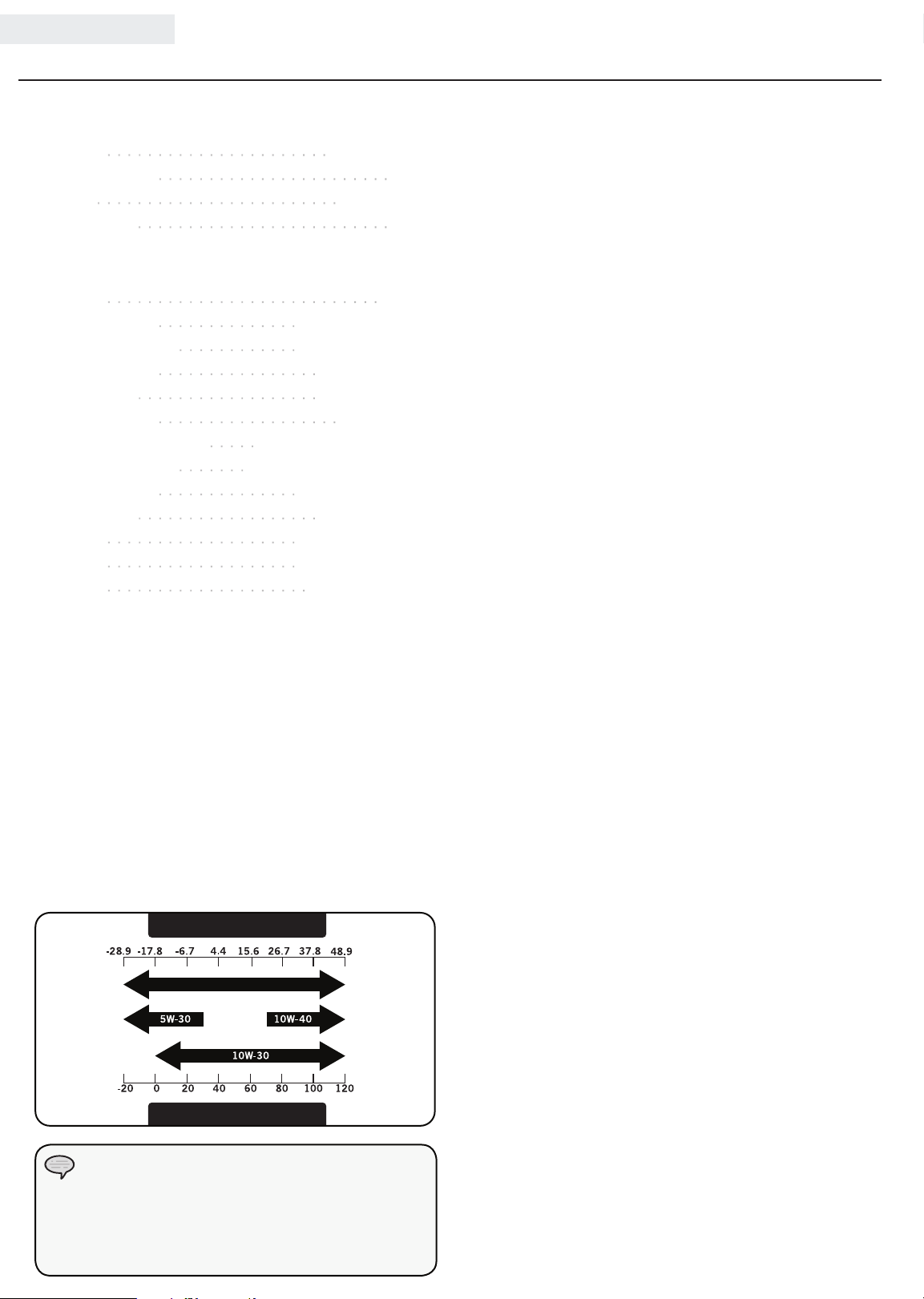
Oil
Use 10W-30 automotive oil.
Oil capacity is 0.6 qt. (0.6 L).
DO NOT OVERFILL.
Please reference the following chart for recommended
oil types for use in the semi-trash pump.
Degrees Celsiusº
Full Synthetic 5W-30
Degrees Fahrenheitº
(Outside)
(Outside)
NOTE
Weather will affect engine oil and engine
performance. Change the type of engine oil used
based on weather conditions to suit the engine
needs.
20
Page 24
SPECIFICATIONS
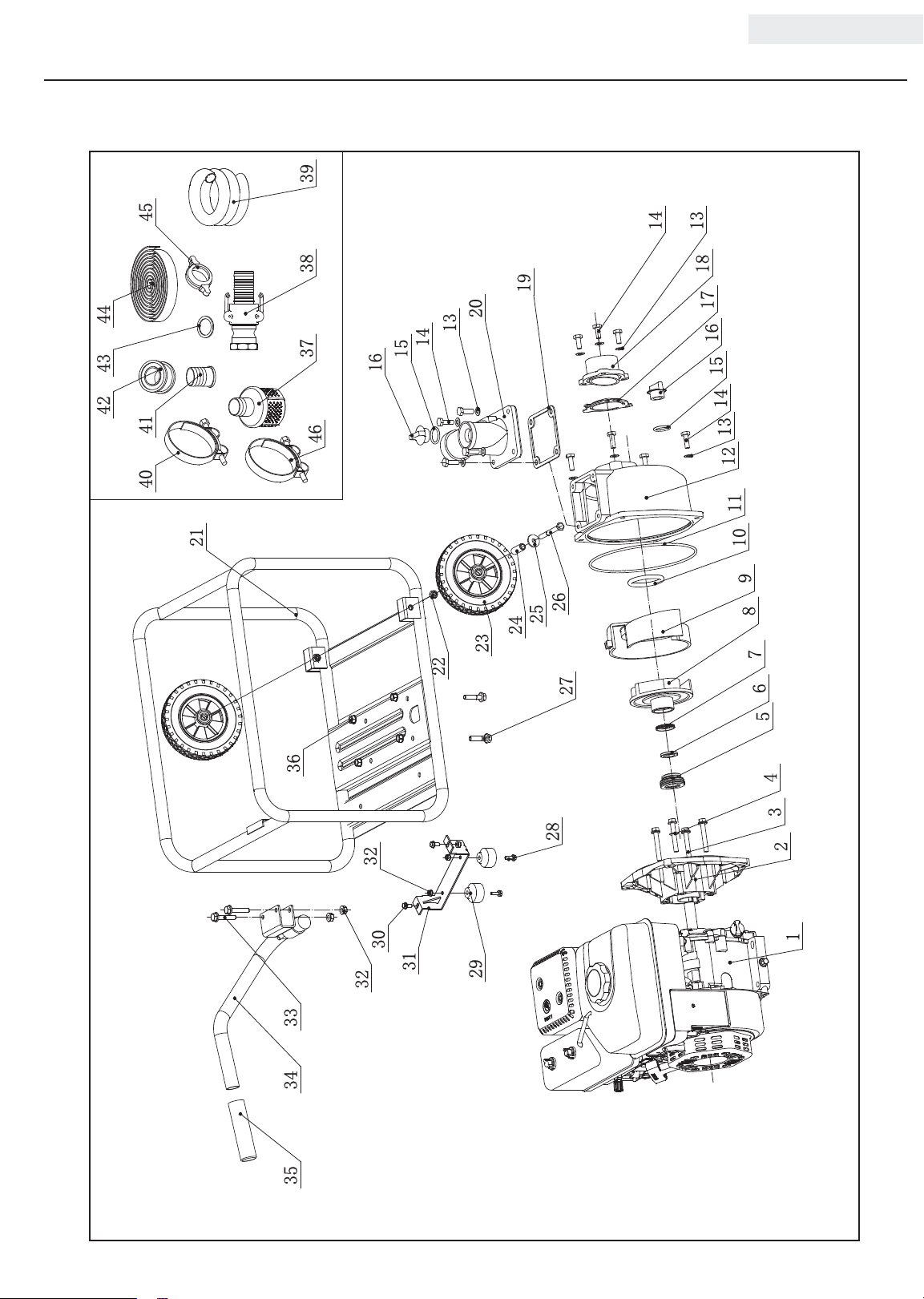
Parts Diagram
ENGLISH 100113
42 43 44
45
40 41
21
37 38 39
46
16
15
14
22
13
20
23
24
19
25
26
27
14
13
18
17
16
15
14
13
12
11
10
9
8
7
6
5
36
333435
32
32
30
31
29
28
4
3
2
1
21
Page 25
100113 ENGLISH
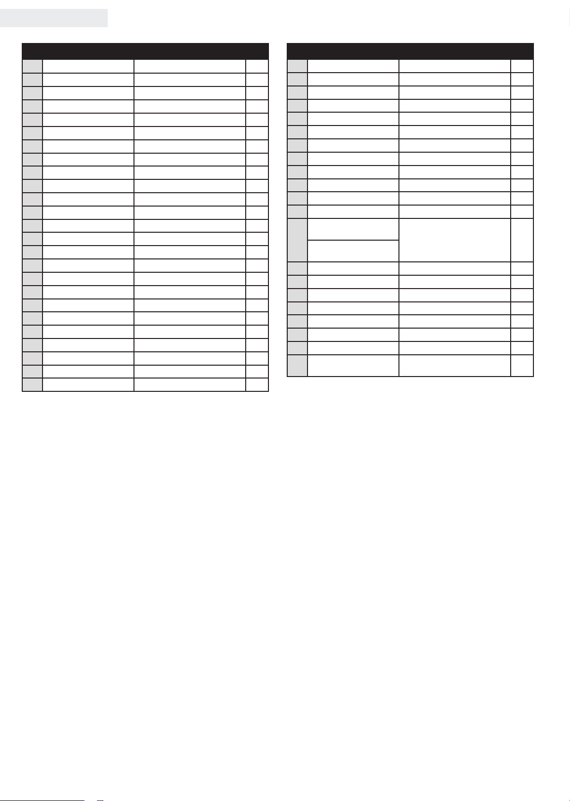
Parts List
# Part Number Description Qty
26.109 Engine, 196cc 1
1
202.251303 .0 0 Pump Base 1
2
1.5789.0855 Flange Bolt M8 x 55 4
3
202.251002.00 Washer Ø8, Copper
4
202.250300.02 Water Seal
5
202.251301.02 Friction-Piece
6
202.251302.00 Seal, Friction-Piece
7
20 2.2 5110 6 .00 Imp eller
8
202.251202.00 Impeller Cover
9
202.251203.00 Seal, Impeller Cover, Ø53 x Ø7
10
20 2.2 51111.0 0 Seal, Base Pump
11
20 2.2 51101.00 Pump Body
12
1.97.1.08 Washer Ø8
13
1.5783.0820 Bolt M8 x 20
14
202. 2514 0 3. 00 Seal, Plug, Ø23.6 x Ø3.55
15
202. 2514 01. 00 Plug
16
20 2.2 5110 5.0 0 One-Way Valve
17
202.251104.02 Inlet Flange
18
20 2.2 5110 3 .0 0 Seal, Outlet Flange
19
202.251102.02 Outlet Flange
20
6.1.124. 2 Frame, 512 x 391 x 419
21
1.6182.10 Lock Nut M10
22
122.201701.05.4 8 8 in. Wheel, Yellow
23
122.200 016. 01 Bushing, Ø16 x Ø10.5 x 58.5
24
1.96.10 Washer Ø10
25
11
# Part Number Description Qty
1.57 82.10105 Bolt M10 x 105
26
1.5789.0835 Flange Bolt M8 x 35
27
1.5789.0825 Flange Bolt M8 x 25
28
252.201400.02 Vibration Mount, Support Leg
4
1
1
1
1
1
1
1
1
7
2
2
1
1
1
1
1
2
2
2
29
1.5789.0 816 Flange Bolt M8 x 16
30
152.200002.00.2 Support Leg, 60 mm
31
1.6177.1.08 Flange Lock Nut M8
32
1.5789.0845 Flange Bolt M8 x 45
33
202.200700.01 Handle
34
152.200702.00 Cover, Handle
35
1.6187.1.08 Lock Nut M8
36
202.250003.01 Strainer
37
202.250001.03
SN: < 20SEP2401284
38
202.250500.01
SN: 20NOV1100001+
9.1800.002 Rigid Intake Hose
39
2.06.044 Clamp, 22 x 54-57 mm, Inlet
40
202.250 0 01.01 Hose Fitting
41
9.1900.001 Teflon Tape
42
202.250002.01 Seal Ring
43
9.1800.001 Collapsible Outlet Hose
44
202.250005.01 Hose Adapter
45
2.06.043
46
Cam Lock Coupler, 2 in.
Clamp, 22 x 52-55 mm,
Outlet, White Zinc
2
2
4
2
2
2
1
6
2
1
1
4
1
1
1
3
1
1
1
1
1
1
22
Page 26
SPECIFICATIONS
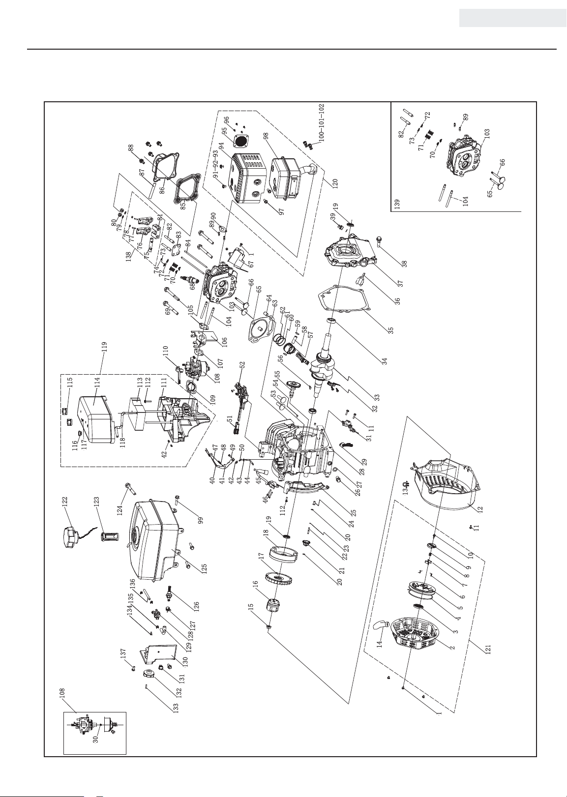
Engine Parts Diagram
ENGLISH 100113
96
95
88
87
86
85
80
79
78
138
119
114
115
117
116
122
118
123
124
134
137
81
82
77
76
75
112
113
136
135
83
84
73
74
72
71
70
69
105
110
111
42
128
129
130
94
91 92 93
90
89
68
103
104
106
107
108
109
51
474849
4041424344
99
125
126
127
98
97
1
67
66
65
64
63
62
61
60
52
50
56
55
54
53
45
46
112
19
18
17
16
15
100 101 102
120
19
39
59
58
57
29
28
27
26
25
24
20
23
22
21
20
139
35
34
33
32
11
31
14
72
82
73
71
70
38
37
36
13
89
103
66
65
104
12
11
10
9
8
7
6
5
4
3
2
121
23
131
108
30
132
133
1
Page 27

100113 ENGLISH
Engine Parts List
# Part Number Description Qty
1.5789.06 08 Flange Bolt M6 x 8 5
1
22.061100.00.2 Cover, Recoil Starter, Black 1
2
21.061005.00 Spring, Recoil Starte r 1
3
2.10. 00 3.1 Rope Ø4 x 1550, Black 1
4
21.0610 01.01 Reel, Recoil Starter 1
5
45.060003.00 Spring, Ratchet 2
6
45.060002.00 Starter Ratchet, Steel 2
7
45.060009.00 Spring, Ratchet Guide 1
8
45.060007.00 Ratchet Guide 1
9
45.060008.00 Screw, Ratchet Guide 1
10
1.578 9.0 612 Flange Bolt M6 x 12 8
11
24.0 8010 0.01.48 Fan Cover, Yellow 1
12
2.05.002 Clamp Ø9.5 x 5 1
13
21.061300.00 Handle, Recoil, Soft 1
14
2.02.006 Nut M14 x 1.5 1
15
21.06 0001.01 Pulley, Starter 1
16
23.080001.00 Cooling Fan 1
17
24.120100.06 Flywheel 1
18
2.11. 0 01 Oil Seal Ø25 x Ø41.3 x 6 2
19
2.03.020.1 Washer Ø6.2 x Ø15 x 0.5, Black 2
20
21.110100 .00 Gear, Governor 1
21
21.110013.00 Shaft, Governor Gear 1
22
21.110 011.0 0 Clip, Gove rnor Gear 1
23
21.110012. 01 Bushing, Govornor Gear, Steel 1
24
23.080600.00 Air Guide, Right 1
25
2.08.037 Drain Bolt M10 x 1.25 x 25 2
26
2.03.016 Washer Ø10 x Ø16 x 1.5, Drain Bolt 2
27
26.030100.00 Crankcase 1
28
21.1204 00 .01 Diode Assembly 1
29
26 .131 017. 0 0 Main Jet, Standard 1
30
26.131017.00 .01 Main Jet, Altitude /
21.127000.02 Oil Level Sensor 1
31
23.050200.0 0 Connecting Rod 1
32
25.050100.02 Crankshaft 1
33
1.276. 620 5 Bearing 6205 2
34
24.030008.00 Gasket, Crankcase Cover 1
35
22.031000.00.48 Oil Dipstick Assembly, Yellow 1
36
24.030007.00 Cover, Crankcase 1
37
1.5789.0832 Flange Bolt M8 x 32 6
38
22.031000.01.48 Oil Filte r Cap, Yellow 1
39
23.110005.01 Spring, T hrottle Return 1
40
21.110003.00 Arm, Governor 1
41
1. 6 17 7. 0 6 Flange Nut M6 3
42
2.03.021.1 Washer Ø6.4 x Ø13 x 1, Black 1
43
21.110001.00 Shaft, Governor Arm 1
44
22.123000.02 Ignition Coil, Shield 1
45
1.5789.0625 Flange Bolt M6 x 25 2
46
23.110006.00 Rod, Governor 1
47
23.110007.00 Spring, Governor 1
48
2.08.040 Bolt M6 x 21, Governor Arm 1
49
21.110008.00 Pin, Shaft 1
50
24.11100 8 .01 .4 8 Grip Sheath, Speed G overnor, Yellow 1
51
24.11100 0 .01 Control A ssembly 1
52
25.040013.00 Lif ter, Valve 2
53
2.04.001 Dowel Pin Ø9 x 14 2
54
26.041000.01 Camshaft 1
55
2.14. 012 Woodruff Key 4 x 7.5 x 19 1
56
26.050005.00 Piston 1
57
23.050003.00 Pin, Piston 1
58
2.09.001 Circlip Ø18 x Ø1 2
59
26.050303.00 Ring, Oil 1
60
26.050302.0 0 Ring, Second Piston 1
61
26.050301.00 Ring, First Piston 1
62
26.030009.00 Gasket, Cylinder Head 1
63
2.04.003 Dowel Pin Ø10 x 14 2
64
23.040002.00 Valve, Intake 1
65
23.040006.00 Valve, Exhaust 1
66
26.0804 00.00 Air Guide, Lower 1
67
2.15.002(F6RT C) Spark Plug F6RTC 1
68
1.5789.08 60 Flange Bolt M8 x 60 4
69
23.040017.00 Oil Se al, Valve 2
70
# Part Number Description Qty
21.040003.00 Spring, Valve 2
71
21.040007.00 Retainer, Exhaust Valve Spring 1
72
21.040001.00 Retainer, Intake Valve Spring 1
73
21.040008.00 Rotator, Exhaust Valve 1
74
24.040202.00 Shaft, Rocker Arm 1
75
22.040009.00 Rocker Arm 2
76
22.040 012.00 Screw, Valve Adjustment 2
77
21.04 00 21.00 Nut M6 x 0.5, Lock 2
78
1.97.1.06 Washer Ø6 2
79
1.6177.1.06 Flange Nut M6 2
80
24.040201.00 Retaine r, Rocker Arm 1
81
23.040010.00 Bolt, Rocker Arm 2
82
24.040004.00 Guide Plate, Push Rod 1
83
23.040005.00 Push Rod 2
84
21.020002.01 Gasket, Cylinder Head Cover 1
85
24.021000.00 Cover, Cylinder Head 1
86
21.020001.00 Breather Tube 1
87
1.578 9.0 615 Flange Bolt M6 x 15 4
88
2.01.010 Stud Bolt M 8 x 35 2
89
26.100001.00 Gasket, Exhaust Pipe 1
90
1.16 674. 0510 Flange Bolt M5 x 10 2
91
1.84 8.05 Washer Ø5 2
92
1.93.0 5 Lock Washer Ø5 2
93
24.101202.00 Muffler P rotector 1
94
46.10130 0. 05 Muffler Screen 1
95
1.818. 0406 Screw M4 x 6 4
96
1.9074.4.0510 Screw /Washer Assembly M5 x 10 2
97
24.10110 0.0 0 Muffler Ass embly 1
98
2.0 8.15 4 Flange Bolt Assembly M6 x 20 3
99
1.617 5.08 Nut M8 2
100
1.84 8.08 Washer Ø8 2
101
1.93.0 8 Lock Washer Ø8 2
102
26. 010100 .0 0 Cylinder Head 1
103
2.01.009 Stud B olt M6 x 110 2
104
24.130002.00 Gasket, Insulator 1
105
23.130001.00 Insulator, Carburetor 1
106
22.130003.00 Gasket, Carburetor 1
107
26.131000.00
108
26.131000.02
21.130004.00 Gasket, Air Cleaner 1
109
21.130100.00 Choke Handle 1
110
24.091100.01 Base, Air Cleaner 1
111
1.5789.062 0 Flange Bolt M6 x 20 2
112
24.091003.02 Element, Air Cleaner 1
113
24.09120 0.02 Cover, Air Cleaner 1
114
24.091600.01 Scr ew Cap, Air Clean C over 2
115
2.12.001 Buffer Ø7.5 x 7.5 1
116
2.06.006 Clamp Ø7 x Ø1 1
117
24.070014.02 Pipe, Fuel Tank To Air Cleaner 1
118
24.091000.02 Air Cle aner Ass embly 1
119
24.101000.00 Muffler A ssembly 1
120
22.061000.00 Recoil Assembly 1
121
24.070100.02 Cap, Fuel Tank 1
122
81.0703 01.00 Fuel Filter, Fuel Tank 1
123
2.0 8.15 6 Flange Bolt Assembly M6 x 33 1
124
24.071000.01 Fuel Tank 1
125
21.070600.03 Joint, Fuel Pipe 1
126
2.06.016 Clamp Ø 8.7 x b8 1
127
24.070400.00 Fuel Vavle 1
128
24.070011.01 Pipe Ø4.5 x (30 + 30 ) 1
129
24.070010.00 Veil, Fuel Tank 1
130
5.1010. 00 3.3 Ignition Switch, Red 1
131
24.070001.00 Fuel Knob 1
132
1.8 18 .0 412 Bolt M4 x 12 1
133
1.16 674. 0512. 2 Flange Bolt M5 x 12 1
134
2.06.007 Clamp Ø 8 x b6 3
135
24.070011.00 Fuel Pipe Ø4.5 x Ø9.5 x 230 1
136
1.578 9.0 612.3 Flange Bolt M6 x 12 2
137
24.040200.00 Rocker Arm Ass embly 1
138
26.010000.00 Cylinder Head Ass embly 1
139
Carburetor 1
24
Page 28
ENGLISH 100113
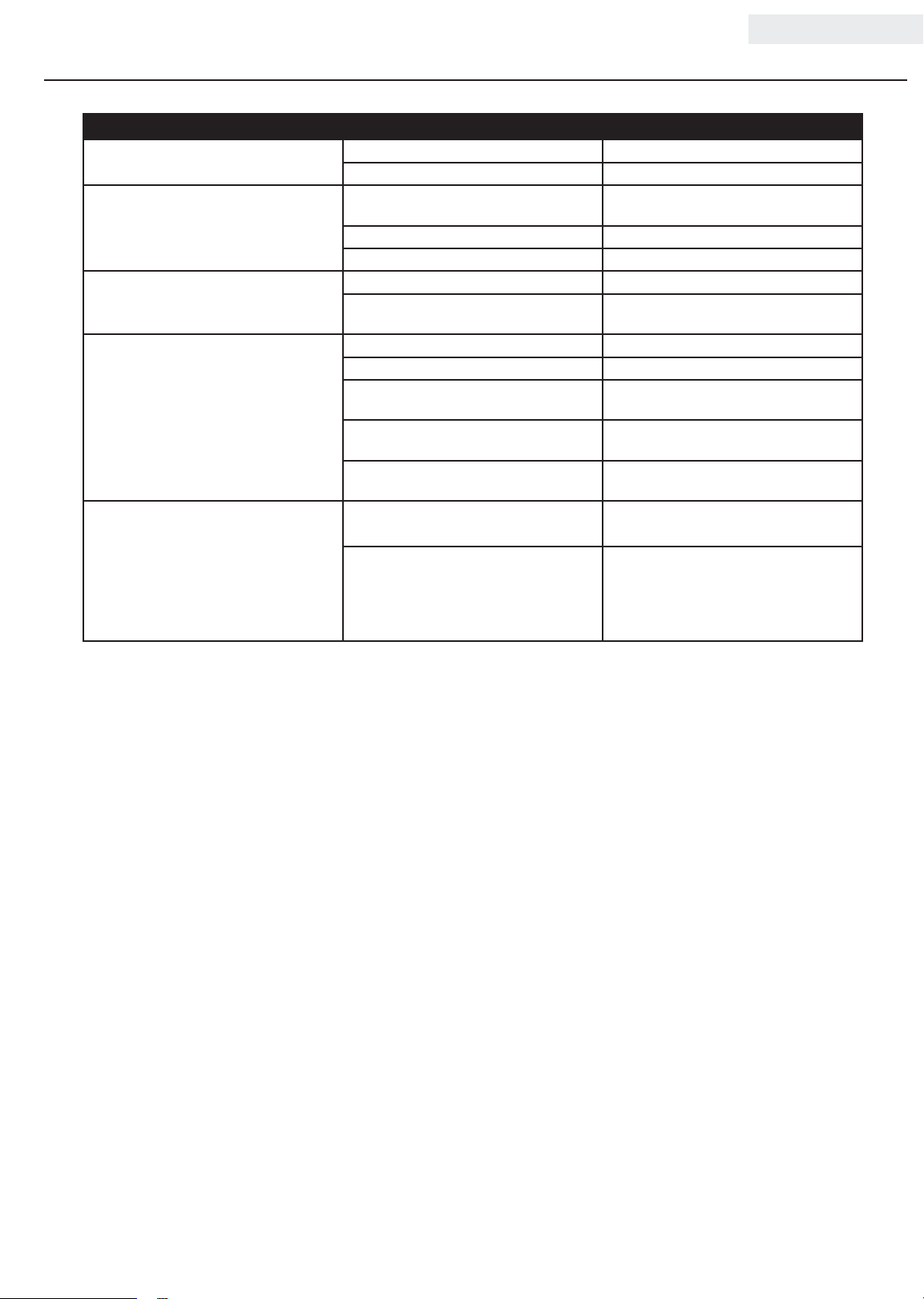
TROUBLESHOOTING
Problem Cause Solution
Semi-trash pump will not start No fuel Add fuel
Faulty spark plug Replace spark plug
Semi-trash pump will not start; Semi-trash
pump starts but runs roughly
Semi-trash pump shuts down during
operation
Semi-trash pump overheating or
performing poorly
Pump will not draw water Water not added to pump Review “Priming the Pump” section of this
Low oil level Fill crankcase to the proper level; place
semi-trash pump on a flat, level surface
Choke in the wrong position Adjust choke
Spark plug wire loose Attach wire to spark plug
Out of fuel Fill fuel tank
Low oil level Fill crankcase to the proper level; place
water transfer pump on a flat, level surface
Strainer or hose clogged Remove debris from strainer or hose
Pump not primed Re-prime pump
Suction hose out of water Place suction hose under the surface of
the water
Head limit exceeded Relocate pump so suction head is less
than discharge head (maximum 98 feet)
Air leak Tighten connectors and clamps or replace
seal packing
manual
Hose clamps on inlet hose are not tight Even small pinhole leak can result in
For further technical support:
Technical Service
Mon – Fri 8:30 AM – 5:00 PM (PST/PDT)
Toll Free: 1-877-338-0999
[email protected]
vacuum loss preventing pump from
priming. Check hose clamps to ensure
they are tight. Adjust clamp position if
necessary.
25
Page 29

WARRANTY*
CHAMPION POWER EQUIPMENT
2 YEAR LIMITED WARRANTY
Warranty Qualifications
To register your product for warranty and FREE lifetime call center
technical support please visit:
https://www.championpowerequipment.com/register
To complete registration you will need to include a copy of the
purchase receipt as proof of original purchase. Proof of purchase
is required for warranty service. Please register within ten (10)
days from date of purchase.
Other Exclusions
This warranty excludes:
– Cosmetic defects such as paint, decals, etc.
– Wear items such as filter elements, o-rings, etc.
– Accessory parts such as hoses, hose fittings, etc.
– Failures due to acts of God and other force majeure events
beyond the manufacturer’s control.
– Problems caused by parts that are not original Champion
Power Equipment parts.
When applicable, this warranty does not apply to products used
for prime power in place of a utility.
Repair/Replacement Warranty
CPE warrants to the original purchaser that the mechanical and
electrical components will be free of defects in material and
workmanship for a period of two years (parts and labor) from
the original date of purchase and 90 days (parts and labor) for
commercial and industrial use. Transportation charges on product
submitted for repair or replacement under this warranty are the
sole responsibility of the purchaser. This warranty only applies to
the original purchaser and is not transferable.
Do Not Return The Unit To The Place Of
Purchase
Contact CPE’s Technical Service and CPE will troubleshoot any
issue via phone or e-mail. If the problem is not corrected by
this method, CPE will, at its option, authorize evaluation, repair
or replacement of the defective part or component at a CPE
Service Center. CPE will provide you with a case number for
warranty service. Please keep it for future reference. Repairs or
replacements without prior authorization, or at an unauthorized
repair facility, will not be covered by this warranty.
Warranty Exclusions
This warranty does not cover the following repairs and equipment:
Normal Wear
Products with mechanical and electrical components need
periodic parts and service to perform well. This warranty does not
cover repair when normal use has exhausted the life of a part or
the equipment as a whole.
Installation, Use and Maintenance
This warranty will not apply to parts and/or labor if the product is
deemed to have been misused, neglected, involved in an accident,
abused, loaded beyond the product’s limits, modified, installed
improperly or connected incorrectly to any electrical component.
Normal maintenance is not covered by this warranty and is not
required to be performed at a facility or by a person authorized by
CPE.
Limits of Implied Warranty and
Consequential Damage
Champion Power Equipment disclaims any obligation to cover
any loss of time, use of this product, freight, or any incidental
or consequential claim by anyone from using this product.
THIS WARRANTY AND THE ATTACHED U.S. EPA and/or CARB
EMISSION CONTROL SYSTEM WARRANTIES (WHEN APPLICABLE)
ARE IN LIEU OF ALL OTHER WARRANTIES, EXPRESS OR IMPLIED,
INCLUDING WARRANTIES OF MERCHANTABILITY OR FITNESS
FOR A PARTICULAR PURPOSE.
A unit provided as an exchange will be subject to the warranty
of the original unit. The length of the warranty governing the
exchanged unit will remain calculated by reference to the purchase
date of the original unit.
This warranty gives you certain legal rights which may change
from state to state or province to province. Your state or province
may also have other rights you may be entitled to that are not
listed within this warranty.
Contact Information
Address
Champion Power Equipment, Inc.
12039 Smith Ave.
Santa Fe Springs, CA 90670 USA
www.championpowerequipment.com
Customer Service
Toll Free: 1-877-338-0999
[email protected]
Fax no.: 1-562-236-9429
Technical Service
Toll Free: 1-877-338-0999
[email protected]
EMERGENCY 24 HOUR SUPPORT: 1- 5 62 -204-118 8
*Except as other wise stipulated in any of the following enclosed Emission Control System Warranties (when applicable) for the Emission C ontrol System: U.S. Environment Protection Agency
(EPA) and/or California Air Resources Board (CA RB).
Page 30

CHAMPION POWER EQUIPMENT, INC. (CPE)
AND THE UNITED STATES ENVIRONMENT PROTECTION AGENCY (U.S. EPA)
EMISSION CONTROL SYSTEM WARRANTY
Your Champion Power Equipment (CPE) engine complies with U.S. EPA emission regulations.
YOUR WARRANTY RIGHTS AND OBLIGATIONS:
The US EPA AND CPE are pleased to explain the Federal Emission Control Systems Warranty on your 2020 small off-road engine (SORE)
and engine powered equipment. New engines and equipment must be designed, built and equipped, at the time of sale, to meet U.S.
EPA regulations for small off-road engines (SORE). CPE warrants the emission control system on your small off-road engine (SORE)
and equipment for the period of time listed below, provided there has been no abuse, neglect, unapproved modification, or improper
maintenance of your equipment.
Your emission control system may include parts such as the carburetor, fuel-injection system, the ignition system, catalytic converter and
fuel lines. Also included may be hoses, belts, connectors and other emission related assemblies. Where a warrantable condition exits, CPE
will repair your small off-road engine (SORE) at no cost to you including diagnosis, parts and labor.
MANUFACTURER’S EMISSION CONTROL SYSTEM WARRANTY COVERAGE:
This emission control system is warranted for two years, subject to provisions set forth below. If, during the warranty period, an emission
related part on your engine is defective in materials or workmanship, the part will be repaired or replaced by CPE.
OWNER WARRANTY RESPONSIBILITIES:
As the small off-road engine (SORE) owner, you are responsible for the performance of the required maintenance listed in your Owner’s
Manual. CPE recommends that you retain all your receipts covering maintenance on your small off-road engine (SORE), but CPE cannot
deny warranty solely for the lack of receipts or for your failure to ensure the performance of all scheduled maintenance.
As the small off-road engine (SORE) owner, you should however be aware that CPE may deny you warranty coverage if your small, off-road
engine (SORE) or a part has failed due to abuse, neglect, improper maintenance or unapproved modifications.
You are responsible for presenting your small off-road engine (SORE) to an Authorized CPE service outlet or alternate service outlet as
described in (3)(f.) below, CPE dealer or CPE, Santa Fe Springs, Ca. as soon as a problem exists. The warranty repairs should be completed
in a reasonable amount of time, not to exceed 30 days.
If you have any questions regarding your warranty rights and responsibilities, you should contact:
Champion Power Equipment, Inc.
Customer Service
12039 Smith Ave.
Santa Fe Springs, CA 90670
1-877-338-0999
Page 31

EMISSION CONTROL SYSTEM WARRANTY
The following are specific provisions relative to your Emission Control System (ECS) Warranty Coverage.
1. APPLICABILITY: This warranty shall apply to 1997 and later model year small off-road engines (SORE). The ECS Warranty Period shall
begin on the date the new engine or equipment is delivered to its original, end-use purchaser, and shall continue for 24 consecutive
months thereafter.
2. GENERAL EMISSIONS WARRANTY COVERAGE
CPE warrants to the original, end-use purchaser of the new engine or equipment and to each subsequent purchaser that each of its
small off-road engines (SORE) is:
2a. Designed, built and equipped so as to conform to U.S. EPA emissions standards for spark-ignited engines at or below 19 kilowatts.
2b. Free from defects in materials and workmanship that cause the failure of a warranted part to be identical in all material respects
to the part as described in the engine manufacturer’s application for certification for a period of two years.
3. THE WARRANTY ON EMISSION-RELATED PARTS WILL BE INTERPRETED AS FOLLOWS:
3a. Any warranted part that is not scheduled for replacement as required maintenance in the Owners Manual shall be warranted for
the ECS Warranty Period. If any such part fails during the ECS Warranty Period, it shall be repaired or replaced by CPE according
to Subsection “d” below. Any such part repaired or replaced under the ECS Warranty shall be warranted for any remainder of the
ECS Warranty Period.
3b. Any warranted, emissions-related part which is scheduled only for regular inspection as specified in the Owners Manual shall be
warranted for the ECS Warranty Period. A statement in such written instructions to the effect of “repair or replace as necessary”,
shall not reduce the ECS Warranty Period. Any such part repaired or replaced under the ECS Warranty shall be warranted for the
remainder of the ECS Warranty Period.
3c. Any warranted, emissions-related part which is scheduled for replacement as required maintenance in the Owner’s Manual shall
be warranted for the period of time prior to the first scheduled replacement point for that part. If the part fails prior to the first
scheduled replacement, the part shall be repaired or replaced by CPE according to Subsection “d” below. Any such emissionsrelated part repaired or replaced under the ECS Warranty, shall be warranted for the remainder of the ECS Warranty Period prior to
the first scheduled replacement point for such emissions-related part.
3d. Repair or replacement of any warranted, emissions-related part under this ECS Warranty shall be performed at no charge to the
owner at a CPE Authorized Service Outlet.
3e. The owner shall not be charged for diagnostic labor which leads to the determination that a part covered by the ECS Warranty is in
fact defective, provided that such diagnostic work is performed at a CPE Authorized Service Outlet.
3f. CPE shall pay for covered emissions warranty repairs at non-authorized service outlets under the following circumstances:
i. The service is required in a population center with a population over 100,000 according to U.S. Census 2000 without a CPE
Authorized Service Outlet AND
ii. The service is required more than 100 miles from a CPE Authorized Service Outlet. The 100 mile limitation does not apply in the
following states: Alaska, Arizona, Colorado, Hawaii, Idaho, Montana, Nebraska, Nevada, New Mexico, Oregon, Texas, Utah and
Wyoming.
3g. CPE shall be liable for damages to other original engine components or approved modifications proximately caused by a failure
under warranty of an emission-related part covered by the ECS Warranty.
3h. Throughout the ECS Warranty Period, CPE shall maintain a supply of warranted emission-related parts sufficient to meet the
expected demand for such emission-related parts.
3i. Any CPE Authorized and approved emission-related replacement part may be used in the performance of any ECS Warranty
maintenance or repair and will be provided without charge to the owner. Such use shall not reduce CPE’s warranty obligation.
3j. Unapproved add-on or modified parts may not be used to modify or repair a CPE engine. Such use voids this ECS Warranty and
shall be sufficient grounds for disallowing an ECS Warranty claim. CPE shall not be liable hereunder for failures of any warranted
parts of a CPE engine caused by the use of such an unapproved add-on or modified part.
Page 32
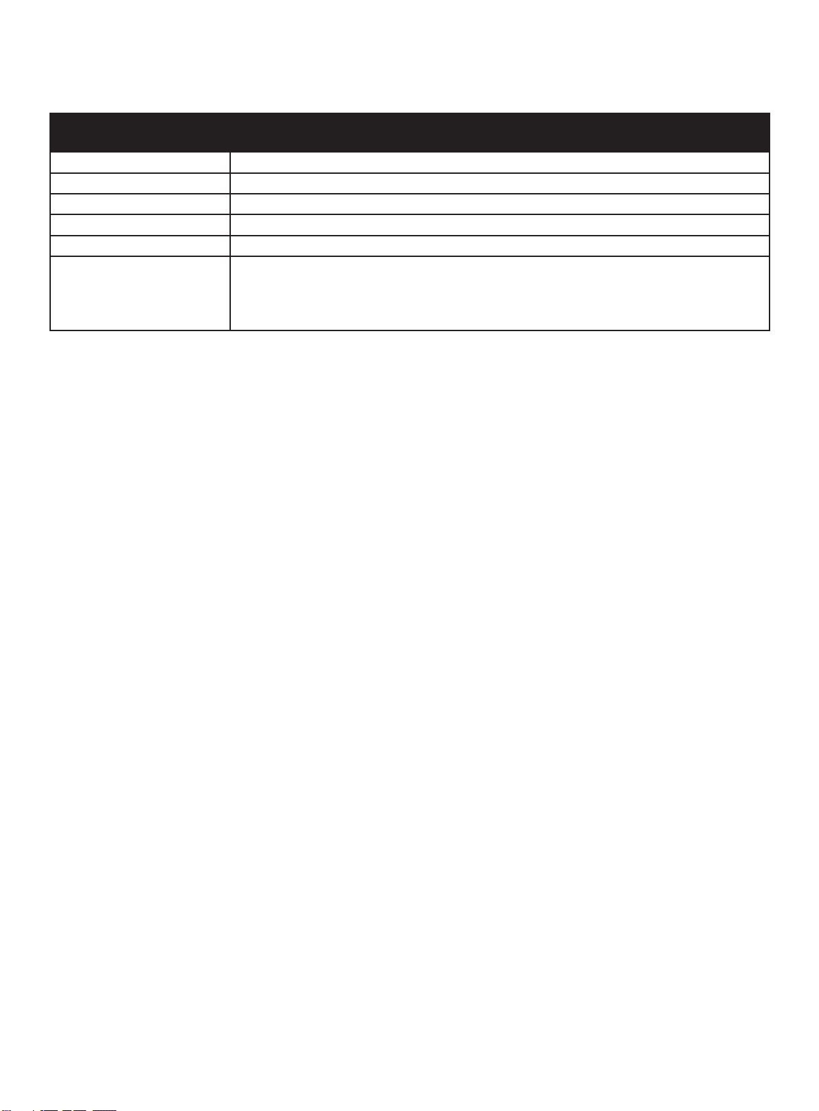
EMISSION-RELATED PARTS INCLUDE THE FOLLOWING: (using those portions of the list applicable to the
engine)
Systems covered by this
warranty
Fuel Metering System Fuel regulator, Carburetor and internal parts
Air Induction System Air cleaner, Intake manifold
Ignition System Spark plug and parts, Magneto ignition system
Exhaust System Exhaust manifold, catalytic converter
Miscellaneous Parts Tubing, Fittings, Seals, Gaskets, and Clamps associated with these listed systems.
Evaporative Emissions Fuel Tank, Fuel Cap, Fuel Line (for liquid fuel and fuel vapors), Fuel Line Fittings, Clamps, Pressure
Relief Valves, Control Valves, Control Solenoids, Electronic Controls, Vacuum Control Diaphragms,
Control Cables, Control Linkages, Purge Valves, Gaskets, Vapor Hoses, Liquid/ Vapor Separator,
Carbon Canister, Canister Mounting Brackets, Carburetor Purge Port Connector
Parts Description
TO OBTAIN WARRANTY SERVICE:
You must take your CPE engine or the product on which it is installed, along with your warranty registration card or other proof of original
purchase date, at your expense, to any Champion Power Equipment dealer who is authorized by Champion Power Equipment, Inc. to
sell and service that CPE product during his normal business hours. Alternate service locations defined in Section (3)(f.) above must be
approved by CPE prior to service. Claims for repair or adjustment found to be caused solely by defects in material or workmanship will not
be denied because the engine was not properly maintained and used.
If you have any questions regarding your warranty rights and responsibilities, or to obtain warranty service, please write or call
Customer Service at Champion Power Equipment, Inc.
Champion Power Equipment, Inc.
12039 Smith Ave.
Santa Fe Springs, CA 90670
1-877-338-0999
Attn.: Customer Service
 Loading...