

Page 1

7721 VCA Stereo Compressor
User’s Manual
Chameleon Labs LLC, Woodinville, WA USA www.chameleonlabs.com 7721 User’s Manual
1
Page 2
Important Safety Instructions
1. Read these instructions.
2. Keep these instructions.
3. Heed all warnings.
CAUTION AVIS
RISK OF ELECTRIC SHOCK
DO NOT OPEN
RISQUE DE CHOC ELECTRIQUE
NE PAS OUVRIR
4. Follow all instructions.
5. Do not use this apparatus near water.
6. Clean only with a dry cloth.
7. Do not block any ventilation openings.
Install in accordance with the manufacturer’s
instructions.
8. Do not install near any heat sources such as
radiators, heat registers, stoves, or other
apparatus (including amplifiers) that produce
heat.
9. Protect the power cord from being walked on
or pinched particularly at plugs, convenience
receptacles, and the point where they exit from
the apparatus.
11.
Only use attachments/accessories specified by
the manufacturer.
12.
Use only with a cart, stand, tripod, bracket, or
table specified by the manufacturer, or sold with
the apparatus. When a cart is used, use caution
when moving the cart/apparatus combination
to avoid injury from tip-over.
13.
Unplug this apparatus during lightning storms
or when unused for long periods of time.
14.
Refer all servicing to qualified service
personnel. Servicing is required when the
apparatus has been damaged in any way, such
as power-supply cord or plug is damaged, liquid
has been spilled or objects have fallen into the
apparatus, the apparatus has been exposed to
rain or moisture, does not operate normally, or
has been dropped.
15.
This apparatus shall not be exposed to dripping
or splashing, and no object filled with liquids,
such as vases or beer glasses, shall be placed on
the apparatus.
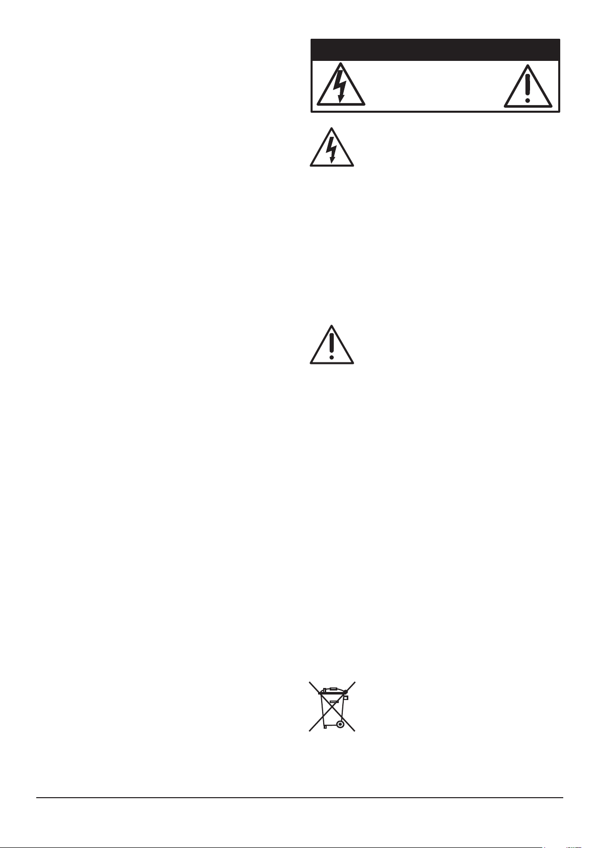
The lightning flash with arrowhead
symbol within an equilateral triangle is
intended to alert the user to the presence
of uninsulated “dangerous voltage”
within the product’s enclosure, that may be
of sufficient magnitude to constitute a risk of
electric shock to persons.
Le symbole éclair avec point de flèche à l’intérieur
d’un triangle équilatéral est utilisé pour
alerter l’utilisateur de la présence à l’intérieur
du coffret de “voltage dangereux” non isolé
d’ampleur suffisante pour constituer un risque
d’éléctrocution.
The exclamation point within an
equilateral triangle is intended to alert
the user of the presence of important
operating and maintenance (servicing)
instructions in the literature accompanying the
appliance.
Le point d’exclamation à l’intérieur d’un
triangle équilatéral est employé pour alerter
les utilisateurs de la présence d’instructions
importantes pour le fonctionnement et
l’entretien (service) dans le livret d’instruction
accompagnant l’appareil.
Caution: to reduce the risk of electric shock, do
not remove cover (or back). No user-serviceable
parts inside Refer servicing to qualified
personnel
Attention: pour eviter les risques de choc
Electrique, ne pas enlever le couvercle. Aucun
Entretien de pieces interieures par l’usager.
Confier L’entretien au personnel qualifie.
Avis: pour eviter les risques d’incendie ou
D’electrocution, n’exposez pas cet article A la
pluie ou a l’humidite
At the end of its useful life, this product must
be carefully and correctly disposed of, and
not placed in with household waste. Please
contact your local, state, or national services
for information regarding the safe disposal of
electronic equipment.
Chameleon Labs LLC, Woodinville, WA USA www.chameleonlabs.com 7721 User’s Manual
2
Page 3

Introduction
Congratulations on your purchase of a fine
Chameleon Labs’ 7721 VCA Stereo compressor. We
hope that it gives you many years of reliable and
high-quality service.
• Dry/Wet control (Full Dry CCW is full
uncompressed signal, Full Wet CW is full
compressed signal
• Output Gain control (-60db to +20dB)
Your 7721 compressor has stereo inputs and outputs
and uses a voltage controlled audio engine to
generate the control voltage that provides the
amount and type of limiting and compression you
desire. It feature a highly effective VU meter, a Wet/
Dry control knob, Peak/RMS detection, Soft and Hard
knee selection as well Threshold, Attack, Release and
Compression ratio controls.
The 7721 has been carefully constructed and
individually tested for quality at our facility in
Woodinville, Washington. It utilizes an ultra low
noise pure, IC based topology.
We have spent three years developing the 7721 and
are extremely pleased to have built this unit for your
use. Although highly influenced by the famous buss
compressors of the 70’s, we have strived to introduce
significant improvements especially in the area of
increased precision for the controls, improved noise
floor and a useful set of features.
• VU Meter selector control (input and outputs
and gain reduction)
• Output Signal Overload LED (+4dB)
Rear Panel Features
• AC Power Input (IEC) and integral fuseholder
• XLR inputs
• XLR outputs
Power Supply
• Internal universal power supply
Limited Warranty
• One year
Features:
• Stereo Inputs / Outputs (balanced XLR’s)
• Selectable Side Chain input (balance XLR)
• Class A/B signal chain topology
• Peak or RMS Detection
• Hard or Soft Knee Compression
• Compression In/Out Switch
• Threshold Control - (-15dB / +15dB)
• High Pass Filter (20, 60, 90, 130 and 200Hz)
• Attack (0.10ms - 30ms)
• Release (0.10s - 1.5s)
• Compression Ratio (between 1.5:1 and 10:1)
Chameleon Labs LLC, Woodinville, WA USA www.chameleonlabs.com 7721 User’s Manual
3
Page 4
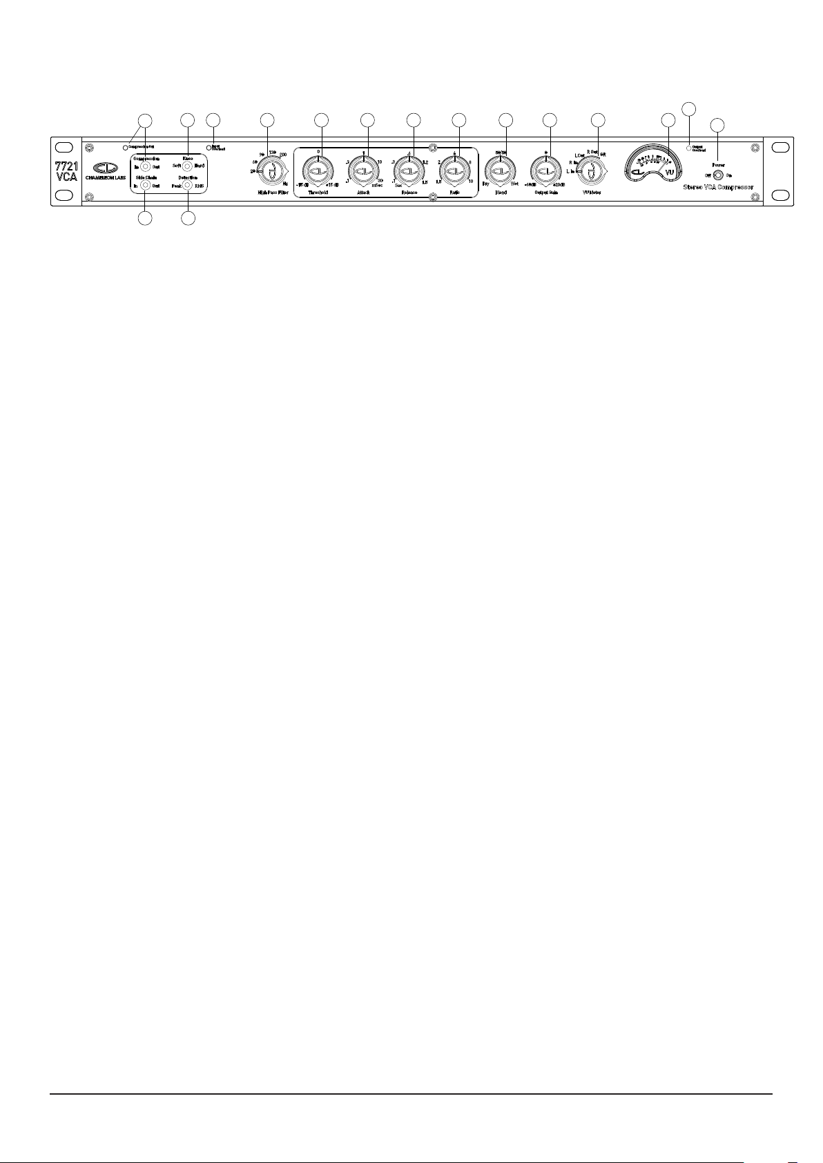
Front Panel Features
3 7 8 9 10 11 12 13 14 15
2
4 5
6
1. Power Switch
When all your connections to and from the
preamplifier have been made, use this switch
to turn the unit on or off. When the unit is
turned ON the VU meter will light up.
2. Compression
This switch turns the compression ON and
OFF. When the compression is OFF, the red
Compression Out LED is ON.
3. Knee
Select between a Soft Knee and Hard Knee
compression curve. (See Graph Page 10)
4. Side Chain
This switch selects the Side Chain input as
the reference audio signal for engaging the
compressor.
5. Detection
This switch allows you to select between Peak
and RMS Detection. The 7721 compressor
engages by analyzing the audio signal
arriving at the Left and Right inputs. Peak
detection engages by looking primarily at
the signal “peaks”. RMS detection engages
by looking at the average RMS power of the
signal waveform.
6. Input Overload
This red LED fires when the input signal
reaches +4dB of signal level.
7. High Pass Filter
This control applies a 24dB per octave High
Pass filter to the audio signal being used
for engaging the compressor. Selectable
frequecies are 20, 60, 90, 130 and 200Hz.
This control is primarily used to keep the
compressor from pumping when analyzing
audio signal with high level, low frequency
content. (See Graph Page 9)
16
1
8. Threshold
This control establishes the level at which the
detector will be engaged. The threshold level
can be set between -15dB and +15dB.
9. Attack
This control establishes the amount of time it
takes the compressor to engage and trigger
compression. You can select between attack
times of .1 and 30 milliseconds.
10. Release
This control establishes the amount of time
it takes for the compressor to release and
return the signal to its initial gain level. The
release time is adjustable between .1 and 1.5
seconds.
11. Ratio
This control establishes the amount of gain
reduction desired which can vary between
ratios of 1.5:1 (mild) and 10:1 (aggressive).
(See Graph Page 10)
12. Blend
This control allows you to listen to an output
signal that contains a “Blend” of compressed
and un-compressed signal. When the knob is
turned full counter clockwise (full Dry), the
output signal contains only uncompressed
signal. At the detent center position the
signal blend is 50/50 and when the knob is
turned full clockwise (full Wet) the output
signal is fully compressed content. This
control blends the two signals only and does
not effect on the compressor settings.
13. Output Gain
This control allows you to boost or attenuate
the output signal level between -60 to +15
dB.
Chameleon Labs LLC, Woodinville, WA USA www.chameleonlabs.com 7721 User’s Manual
4
Page 5

14. VU Meter Control
This five position control allows monitoring
of Input and Output channels as well as Gain
Reduction.
15. VU Meter
This precision VU meter shows either the
input, output or gain reduction levels,
depending upon the position of the VU Meter
control switch (14).
16. Output Overload
This LED will light when the output levels are
overloaded. Carefully adjust the Output Gain
control (13) so this LED does not come on,
during louder passages.
Chameleon Labs LLC, Woodinville, WA USA www.chameleonlabs.com 7721 User’s Manual
5
Page 6
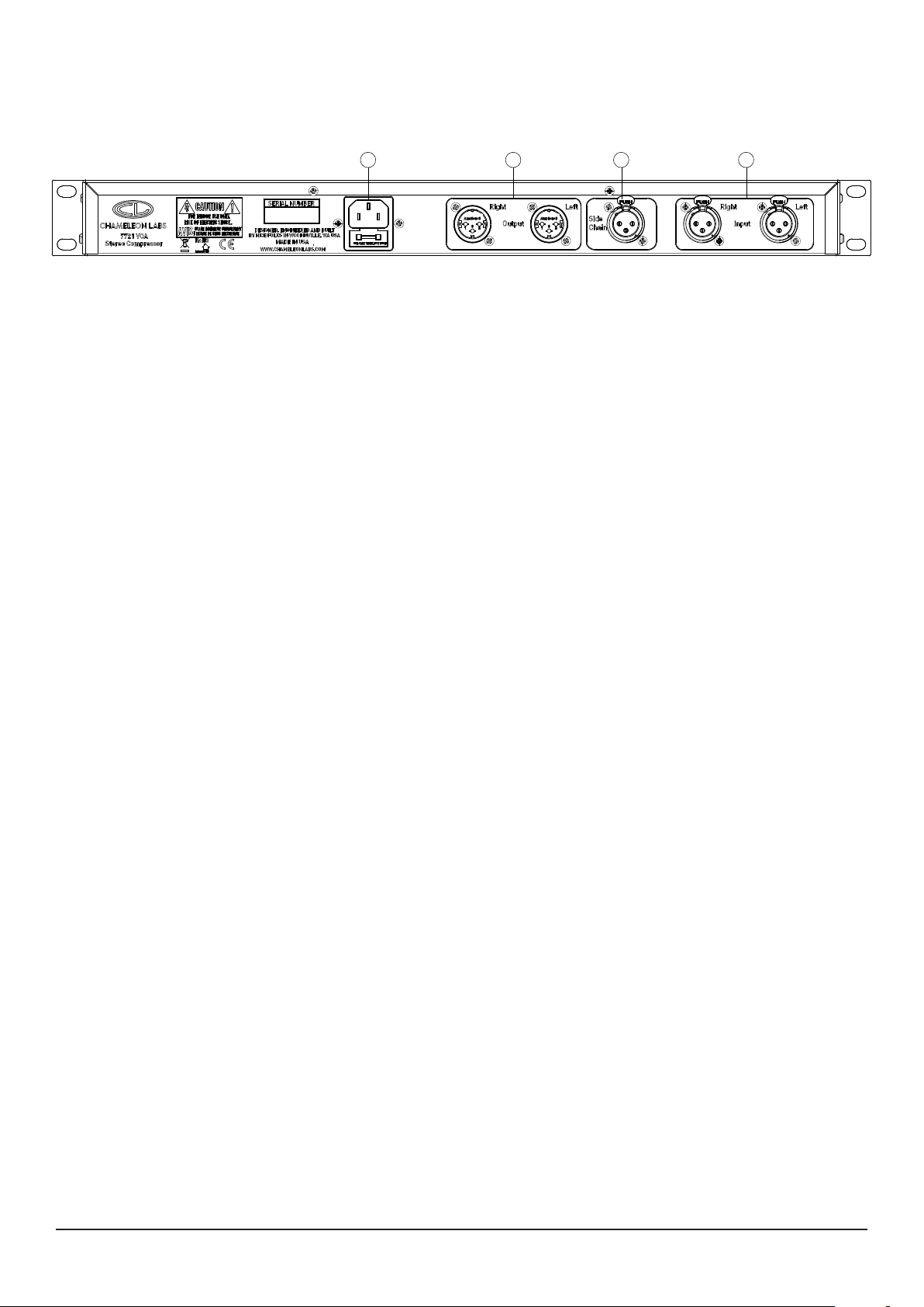
Rear Panel Features
1
1. AC Power Input
The unit contains a universal power supply
that will operate with AC mains voltages from
100 VAC to 240 VAC at 50/60 Hz.
Connect one end of the supplied AC power
cord to this input, and the other end to an AC
mains supply.
The AC input has its own integral fuseholder.
Before changing or inspecting the AC fuse,
turn off the unit and unplug the power cord
from the AC mains supply. Use only the
specified fuse. If the fuse is replaced and
blows again, please contact your dealer for
repair. DO NOT use a larger fuse.
2
3 4
3. Side Chain Input
This input allows connection of a line input
for use as a stand alone trigger signal for the
compressor.
4. Stereo Inputs
Connect the stereo output of your line-level
device to these inputs.
These female XLR connectors are wired with
pin 2 HOT, pin 3 common, and pin 1 ground
(shield).
2. Stereo Outputs
Connect this to the line-level input section of
a mixer or to other devices such as Analog to
Digital converters etc.
These male XLR connectors are wired with
pin 2 HOT, pin 3 common, and pin 1 ground
(shield).
Chameleon Labs LLC, Woodinville, WA USA www.chameleonlabs.com 7721 User’s Manual
6
Page 7

Initial set up of the Model 7721
1. Mute your monitors or headphones and make
your connections to the rear panel. These
connections are commonly made to a patch
bay panel or to a channel or bus insert on a
mixer.
2. Turn ON the unit.
3. Set the Compression switch to IN position
4. Set the Side Chain to Out position
5. Set the Knee switch to either Soft or Hard
6. Set the Detection switch to either Peak or
RMS
7. Set the High Pass switch to 20
8. Set the Blend control to full clockwise (Wet)
position.
9. Set the Compression switch to the IN position
10. Set the Threshold control to full clockwise
position (+15dB)
11. Set the Attack knob to 1ms (12 o’clock)
12. Set the Release knob to .6s (12 o’clock)
13. Set the Threshold control to full clockwise
position (+15dB)
14. Set the Ratio control knob to 4:1
15. Set the VU Meter switch to Left or Right Input
settings and verify that the incoming input
levels are within a usable range (-10 to -3dB)
16. Set the VU Meter switch to Left or Right
Output settings and verify that the output
levels are at maximum usbale levels within a
feasable range (-10 to -3dB) using the Output
Gain control
17. Set the VU Meter switch to GR (Gain
Reduction)
18. Lower the Threshold level control by turning
the knob counter clockwise and you hear and
see Gain Reduction engaged.
Chameleon Labs LLC, Woodinville, WA USA www.chameleonlabs.com 7721 User’s Manual
7
Page 8
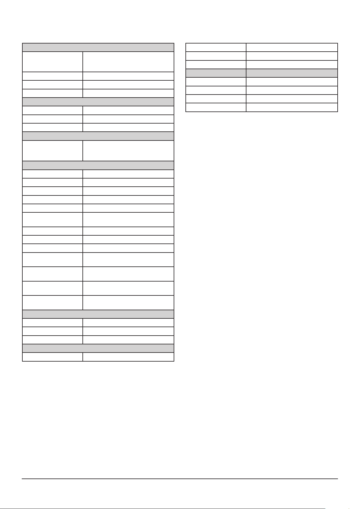
Technical Specications
General Specifications
Noise < 120dB with compression out
Output Type Transistor Class AB to drive 10kΩ
Maximum Output +20 dBu into 600Ω load impedance
Frequency Response 10Hz - 50kHz -0.5 dB
Indicators
Meter Light
Red
Red
Internal Power Supply
100 to 240 VAC (50/60 Hz)
User Controlled Functions
ON Switch Turn Pre Amp ON - VU meter light on
Compression Switch In / Out
Side Chain Switch In / Out
Knee Switch Soft / Hard
Detection Switch Peak / RMS
High Pass Filter Switch Provides a 24dB/octave high pass filter at
Threshold Control Sets Threshold level (-15dB to +15dB)
Attack Control Sets Attack time between .1 and 30ms
Release Control Sets Release time between .1 and 1.5s
Ratio Control Sets compression ratio between 1.5:1 and
Blend Control Blends the uncompressed audio signal with
Output Gain Control Provides output gain control between -60db
VU Meter Switch Selects VU Meter drive signal between input,
Inputs/Outputs
Stereo Inputs IC Based Class AB Balanced Circuit
Side Chain IC Based Class AB Balanced Circuit
Stereo Outputs IC Based Class AB Balanced Circuit
Physical Specifications
Noise level is gain reduction dependent with
compression engaged
Power ON
Compressor Out
Output Overload
Switch mode power supply, fully shielded
Quiescent Consumption 0.5 Watts
Peak Output 3 Amp
20Hz, 60Hz, 90Hz, 130Hz and 200Hz
10:1
the compressed signal path
and +20dB
output and gain reduction signal paths
Depth
280mm / 11.02 inches
Box Size
Height
44.5mm / 1.75 inches (1 RU)
Width
480mm / 19 inches
Weight
4.4 kg / 9.7 lbs
Depth
400mm / 15.75 inches
Height
150mm / 5.90 inches
Width
620mm / 24.4 inches
Weight
6.1 kg / 13.4 lbs
Chameleon Labs reserves the right to change these
specifications at any time without notice. Not to be a pain, but
to improve things in general.
Chameleon Labs is a trademark of Chameleon Labs LLC.
All other brand names mentioned are trademarks or registered
trademarks of their respective holders, and are hereby
acknowledged.
©2019 Chameleon Labs. All Rights Reserved.
Chameleon Labs LLC, Woodinville, WA USA www.chameleonlabs.com 7721 User’s Manual
8
Page 9
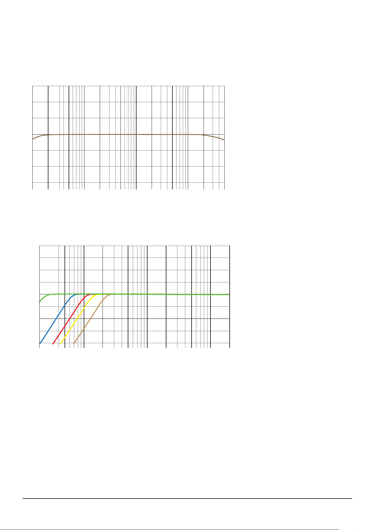
Typical Performance Graphs
50k
Frequency Response
+9
Frequency Response
+6
+3
0
dB
-3
-6
-9
10
20
50 100 200 500 1k 2k 5k 10k 20k
Hertz
Control Signal High Pass Filter - 20Hz, 60Hz, 90Hz, 130Hz, 200Hz
+24
+18
+12
+6
This graph shows the frequency
response
High Pass Filter
The high-pass crossover frequency
can be selected from 20, 60, 90,
130 and 200 Hz.
0
-6
-12
-18
-24
20 50 100 200 500 1k 2k 5k 10k 20k
Chameleon Labs LLC, Woodinville, WA USA www.chameleonlabs.com 7721 User’s Manual
9
Page 10
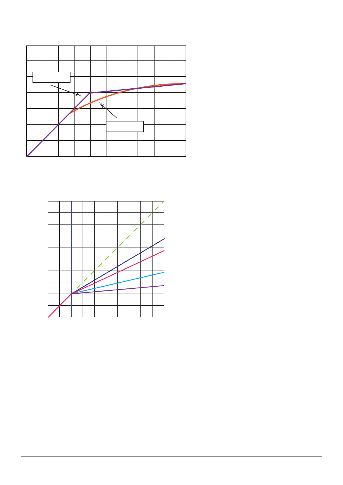
Typical EQ Performance Graphs
Hard Knee
Soft Knee
Soft Knee vs Hard Knee
compression curve
Output
Level (dB)
Threshold
+35
+30
+25
+20
+15
+10
+5
0
-5
-10
-15 -10 -5 0 +5 +10 +15 +20 +25 +30 +35
Input Level (dB)
1:1
1.5:1
2:1
4:1
10:1
Typical compression curves with
threshold set to -5dB, hard knee
and RMS detection
Compression
Ratio
Chameleon Labs LLC, Woodinville, WA USA www.chameleonlabs.com 7721 User’s Manual
10
Page 11

Chameleon Labs LLC, Woodinville, WA USA www.chameleonlabs.com 7721 User’s Manual
11
Page 12

Warranty and Liability
Your Chameleon Labs product is warranted to the original owner for a period of one year. Chameleon
Labs guarantees this product to be free from electrical and mechanical defects and will repair or
replace defective components, or replace the unit at Chameleon Lab’s option. Should service be
required for your Chameleon Labs product, please contact the manufacturer. Service is provided for
products beyond the warranty period. Seller warrants that the goods are described in this agreement,
but no other express warranty is made in respect to the goods. The entire risk as to the quality and
performance of the good is with the buyer. Seller disclaims all warranties either expressed or implied,
including any implied warranty of merchantability or fitness for a particular purpose, and seller
neither assumes nor authorizes any other person to assume for it any liability in connection with the
sale of said goods.
MODEL NUMBER ----------------------------------------------------------------------------
SERIAL NUMBER ----------------------------------------------------------------------------
DATE OF PURCHASE ----------------------------------------------------------------------------
PURCHASED FROM ----------------------------------------------------------------------------
----------------------------------------------------------------------------
----------------------------------------------------------------------------
Please visit www.chameleonlabs.com for the latest updates and technical information.
Chameleon Labs LLC, Woodinville, WA USA www.chameleonlabs.com 7721 User’s Manual
12
 Loading...