

Page 1

Updated: 5/11/2022
Lightweight End Fed
Halfwave Sloper
(CHA LEFS 8010)
Operator’s Manual
Nevada - USA
WWW.CHAMELEONANTENNA.COM
VERSATILE – DEPENDABLE – STEALTH – BUILT TO LAST
Page 2

CHA LEFS 8010 Page 2
Table of Contents
Introduction .............................................................................................................................................. 3
HF Propagation ......................................................................................................................................... 3
Parts of the Antenna ................................................................................................................................. 5
Antenna Configurations ............................................................................................................................ 7
Antenna Installation .................................................................................................................................. 8
Recovery Procedure .................................................................................................................................. 9
Troubleshooting ...................................................................................................................................... 10
Specifications .......................................................................................................................................... 10
Warranty ................................................................................................................................................. 12
Accessories .............................................................................................................................................. 12
Chameleon AntennaTM Products ............................................................................................................ 12
References .............................................................................................................................................. 13
WARNING! Never mount this, or any other antenna near power lines or utility wires! Any materials:
ladders, ropes, or feedlines that contact power lines can conduct voltages that kill. Never trust insulation to protect
you. Stay away from all power lines.
WARNING! Never operate this antenna where people could be subjected to high levels of RF exposure,
especially above 10 watts or above 14 MHz. Never use this antenna near RF sensitive medical devices, such as
pacemakers.
Photographs and diagrams in this manual may vary slightly from current production units due to manufacturing
changes that do not affect the form, fit, or function of the product.
All information on this product and the product itself is the property of and is proprietary to Chameleon AntennaTM.
Specifications are subject to change without prior notice.
!
!
Page 3

CHA LEFS 8010 Page 3
Introduction
Thank you for purchasing and using the Chameleon Antenna
TM
Lightweight End Fed Half Wave Sloper (CHA
LEFS 8010). The CHA LEFS 8010 is an eight band, no-tuner, High Frequency (HF) antenna for use on the
80, 40, 30, 20, 17, 15, 12, and 10 meter Amateur Radio Service (ham) bands. Its’ minimalistic design and
lightweight components, shown in plate (1), are intended for the serious backpacker and outdoor
adventurer use. Leave the tuner and SWR meter at home – just bring a radio and a pair of hiking boots!
Plate 1. CHA LEFS 8010 Antenna.
The CHA LEFS 8010 is designed for the trail. The
sturdy line winder with integral high-efficiency
impedance matching network transformer,
ultra-thin 20 gauge PTFE antenna wire, and
Micro 90 paracord enables highly portable
operation without the extra bulk of an antenna
tuner. Setup is quick and easy and the antenna
will operate without a tuner or adjustment on
the entire 80, 40, 30, 20, 17, 15, 12, and 10 meter
ham bands. The antenna can also be used on 60
meters with an antenna tuner. When ready to
be packed, the CHA LEFS 8010 doesn’t take up
much space in your backpack – it is only eight
inches long, four inches wide, and weighs only
1.5 pounds. The CHA LEFS 8010 is perfect for
backpackers, hikers, bikers, campers, and
survival communication. The subdued color
scheme make it nearly disappear in the field.
The CHA LEFS 8010 is also configurable to
facilitate Near-Vertical Incident Sky wave (NVIS)
communication. Antennas built by Chameleon
Antenna
TM
are versatile, dependable, stealthy,
and built to last. Please read this operator’s
manual so that you may maximize the utility you
obtain from your CHA LEFS 8010.
HF Propagation
HF radio provides relatively inexpensive and reliable local, regional, national, and international voice and
data communication capability. It is especially suitable for undeveloped areas where normal
telecommunications are not available, too costly or scarce, or where the commercial telecommunications
infrastructure has been damaged by a natural disaster or military conflict.
Although HF radio is a reasonably reliable method of communication, HF radio waves propagate through
a complex and constantly changing environment and are affected by weather, terrain, latitude, time of
day, season, and the 11-year solar cycle. A detailed explanation of the theory of HF radio wave
propagation is beyond the scope of this operator’s manual, but an understanding of the basic principles
will help the operator decide what frequency and which of the CHA LEFS 8010 configurations will support
their communication requirements.
Page 4

CHA LEFS 8010 Page 4
HF radio waves propagate from the transmitting antenna to the receiving antenna using two methods:
ground waves and sky waves.
Ground waves are composed of direct waves and surface waves. Direct waves travel directly from the
transmitting
antenna to the receiving antenna when they are within the radio line-of-sight. Typically, this distance is 8
to 14 miles for field stations. Surface waves follow the curvature of the Earth beyond the radio horizon.
They are usable, during the day and under optimal conditions, up to around 90 miles, see table (1). Low
power, horizontal antenna polarization, rugged or urban terrain, dense foliage, or dry soil conditions can
reduce the range very significantly. The U.S. Army found that in the dense jungles of Vietnam, the range
for ground waves was sometimes less than one mile.
Frequency
Distance
Frequency
Distance
2 MHz
88 miles
14 MHz
33 miles
4 MHz
62 miles
18MHz
29 miles
7 MHz
47 miles
24 MHz
25 miles
10 MHz
39 miles
30 MHz
23 miles
Table 1. Maximum Surface Wave Range by Frequency.
Sky waves are the primary method of HF radio wave propagation. HF radio waves on a frequency below
the critical frequency (found by an ionosonde) are reflected off one of the layers of the ionosphere and
back to Earth between 300 and 2,500 miles, depending upon the frequency and ionospheric conditions.
HF radio waves can then be reflected from the Earth to the ionosphere again during multi-hop propagation
for longer range communication. The most important thing for the operator to understand about HF radio
wave propagation is the concept of Maximum Usable Frequency (MUF), Lowest Usable Frequency (LUF),
and Optimal Working Frequency (OWF). The MUF is the frequency for which successful communications
between two points is predicted on 50% of the days of in a month. The LUF is the frequency below which
successful communications are lost due to ionospheric loses. The OWF, which is somewhere between the
LUF and around 80% of the MUF, is the range of frequencies which can be used for reliable
communication. If the LUF is above the MUF, HF sky wave propagation is unlikely to occur.
The HF part of the Radio Frequency (RF) spectrum is usually filled with communications activity and an
experienced operator can often determine where the MUF is, and with less certainty, the LUF by listening
to where activity ends. The operator can then pick a frequency in the OWF and attempt to establish
contact. Another method is using HF propagation prediction software, such as the Voice of America
Coverage Analysis Program (VOACAP), which is available at no cost to download or use online at
www.voacap.com. The operator enters the location of the two stations and the program show a wheel
with the predicted percentage of success based on frequency and time. ALE, which is the standard for
interoperable HF communications, is an automated method of finding a frequency in the OWF and
establishing and maintaining a communications link.
Page 5

CHA LEFS 8010 Page 5
Even under optimal conditions, there is a gap between where ground waves end (around 40 to 90 miles)
and the sky wave returns to Earth on the first hop (around 300 miles). NVIS propagation can be used to
fill this gap. The frequency selected must be below the critical frequency, so NVIS is can normally only be
used on frequencies from around 2 to 10 MHz. Frequencies of 2 – 4 MHz are typical at night and 4 – 8
MHz during the day.
Parts of the Antenna
The CHA LEFS 8010 is comprised of the following components, see plates (2) and (3). The letter
references are used to identify components of the antenna in the detailed installation instructions.
Plate 2. Components of the CHA LEFS 8010 Antenna.
A. Line Winder Assembly. The Line Winder Assembly is a unitary assembly comprised of the
components and sub-components that make up the Lightweight End Fed Half Wave Sloper antenna.
It functions as the suspension and feed point of the antenna when erected and convenient storage
for the Antenna Wires and Paracord when not in use.
B. Suspension Point. The Suspension Point is the large hole in the top of the Line Winder Assembly,
which is used to attach the Paracord for suspension of the antenna feed point.
C. Antenna Wire. The Antenna Wire is permanently attached to Line Winder Assembly. It is
comprised of 63 feet of strong, lightweight 20-gauge copper-clad Kevlar PTFE wire and a small
loading coil.
Page 6
CHA LEFS 8010 Page 6
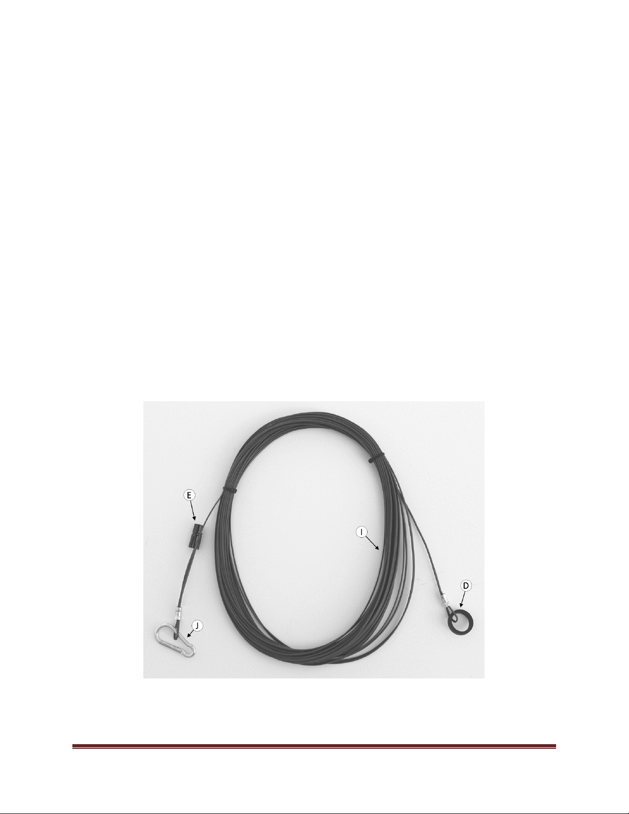
D. Insulator Loop. An Insulator Loop is permanently installed on the far end of the Antenna Wire.
E. Extension Connector. The Extension Connector is located on the far end of the Antenna Wire and is
used to attach the 80 meter Antenna Wire. It is not used otherwise.
F. UHF Connector Socket. The UHF Connector Socket (SO-239) is located on the back of the Line
Winder Assembly and is used to connect the Coaxial Cable to the antenna.
G. Paracord. The Paracord is a 50-foot length of lightweight Micro 90 paracord used to suspend the
antenna.
H. Coaxial Cable. The Coaxial Cable (not supplied) is used to connect the antenna to the radio set. RG-
58 with an integrated RFI Choke, such as that sold by Chameleon AntennaTM, is recommended.
I. Antenna Wire Extension. The Antenna Wire Extension is 67 feet of lightweight 20-gauge copper-
clad Kevlar PTFE wire, which is used to configure the CHA LEFS 8010 as an 80 Meter End Fed Half
Wave antenna.
J. Carabiner. The Carabiner is used to mechanically attach the 80 Meter Antenna Wire to the end of
the standard Antenna Wire and provide strain relief.
Plate 3. Components of the Antenna Wire Extension.
Page 7

CHA LEFS 8010 Page 7
Antenna Configurations
The two basic configurations for the CHA LEFS 8010 are as an End Fed Sloper and an End Fed Horizontal
antenna. Figure (1) shows the Sloper configuration, which is the normal configuration. When installed at
around 25 feet, this antenna will provide good general-purpose communication. There is some directivity
broadside to the antenna on 40 meters and towards the ends of the antenna on 20 meters and above.
The main advantage of the Sloper for portable operation is that it requires only one end support and is
fast and easy to setup.
Figure 1. CHA LEFS 8010 Sloper Configuration.
Figure (2) shows the End Fed Horizontal NVIS configuration. By reducing the height of the antenna to
around 15 feet, and making the antenna wire horizontal, you can enhance NVIS propagation. You will
need another support and an additional length of paracord for the far end of the antenna.
Figure 2. CHA LEFS 8010 Horizontal NVIS Configuration.
Page 8
CHA LEFS 8010 Page 8
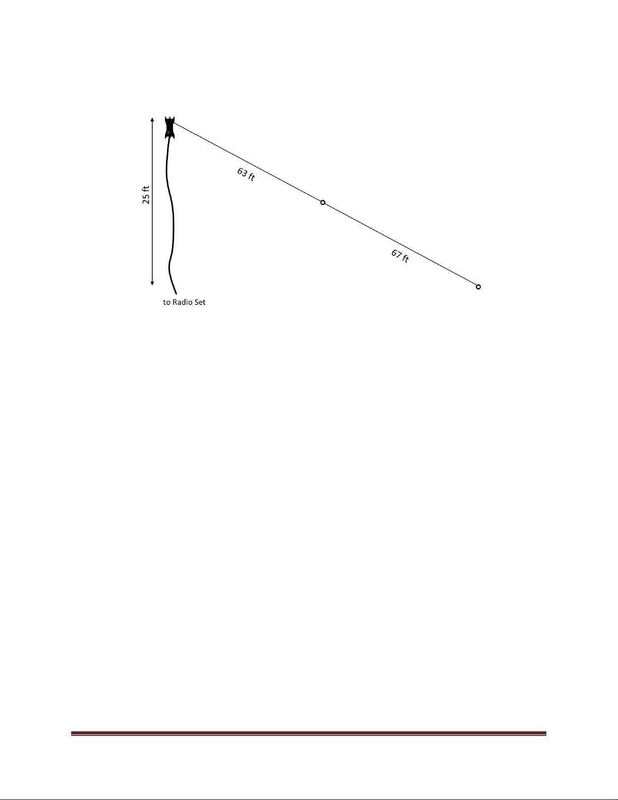
Figure (3) shows the 80 Meter End Fed Sloper configuration, which uses the 80 Meter Antenna Wire
extension. The antenna can also be installed in the Horizontal NVIS configuration.
Figure 3. CHA LEFS 8010 80 Meter Sloper Configuration.
Antenna Installation
Use the following procedure to install the CHA LEFS 8010 Sloper configuration.
Site Selection and Preparation.
1. Select a site to deploy the CHA LEFS 8010
Sloper configuration. The site must have a
support that will position the Line Winder
Assembly at a height of around 15 to 25 feet.
If the right support is not available, any
available support can be used, such as a
fence post, hiking pole, or fishing pole with
reduced performance.
Raise the Antenna.
2. If not already attached, using a Bowline, or
similar knot, attach the Paracord (G) to the
Suspension Point (B) of the Line Winder
Assembly (A); otherwise unwrap the
Paracord from the Line Winder Assembly.
3. Using a throw weight or some other method,
loop the Paracord over the support.
4. Unwrap the Antenna Wire (C) from the Line
Winder Assembly.
5. Connect the Coaxial Cable to the Line Winder
Assembly UHF Connector Socket (F). A right
angle elbow adapter is recommended to
reduce strain on the Coaxial Cable.
6. Raise the Line Winder Assembly to the
desired height and secure it to the support
using a Round Turn and two Half Hitches, or
similar knot.
Finish Installation.
7. Fully extend the Antenna Wire, allowing
some sag in the wire. Do not make the
Antenna Wire taut. The Antenna Wire is
made from lightweight 20-gauge copperclad Kevlar PTFE wire. Although it is strong,
compared to similar gauge wire, it is not as
strong as heavier gauge wire. It very is
important not to over-tension the wire or it
may break.
Page 9

CHA LEFS 8010 Page 9
If you are not using the 80 Meter Antenna Wire
Extension, skip to step 10.
Refer to plate (4) for the next two steps.
Plate 4. Antenna Wire Extension Connection.
8. Attach the Carabiner (J) from the end of the
Antenna Wire Extension to the Isolator Loop
(D) on the end of the Antenna Wire.
9. Connect the two Antenna Wire Extension
Connectors (E) together.
10. Insert a Tent Peg (not supplied) through the
Insulator Loop (D) and drive the Tent Peg
into the ground to secure the far end of the
Antenna Wire. Alternatively, you can attach
a short length of high-stretch rope or shock
cord (not supplied) to the Insulator Loop and
tie the end of the Antenna Wire to a small
tree or other fixed object.
11. Connect the Coaxial Cable to the Radio Set
and perform an operational test.
Recovery Procedure
To recover the CHA LEFS 8010, perform the following steps:
1. Disconnect the Coaxial Cable from the radio set.
2. Lower the Line Winder Assembly to the ground.
3. Disconnect the Coaxial Cable from the Line Winder Assembly.
4. Carefully roll (do not twist) the Coaxial Cable.
5. Detach the far end of the Antenna Wire.
6. Wrap the Antenna Wire (and Antenna Wire Extension, if used) around the Line Winder Assembly in
the area shown in plate (5).
7. Wrap the Paracord around the Line Winder Assembly in the area shown in plate (5).
8. Secure the windings with the attached shock cord.
9. Remove dirt from antenna components and inspect them for signs of wear.
10. Stored antenna and antenna components in your backpack.
Plate 5. Recovered Antenna.
Page 10

CHA LEFS 8010 Page 10
Troubleshooting
1. Inspect the Antenna Wire and Loading Coil for breakage, corrosion, or signs of strain.
2. If using the Antenna Wire Extension, ensure the Extension Connectors are making a good
connection.
3. Ensure the UHF Connector Plugs are securely tightened.
4. Inspect the Coaxial Cable assembly for cuts in insulation or exposed shielding. Replace if damaged.
5. If still not operational, connect a Standing Wave Ratio (SWR) Power Meter and check SWR.
6. If SWR is greater than 3:1 on specified bands, replace Coaxial Cable. Most problems with antenna
systems are caused by the coaxial cables and connectors.
7. If still not operational, contact Chameleon AntennaTM Technical Support. Explain to them what
specifically does not work correctly about the antenna, the steps you have taken during
troubleshooting, and those results.
Specifications
• Frequency:
o 3.5 – 4.0 MHz (80m) (when using Antenna Wire Extension)
o 7.0 - 7.3 MHz (40m)
o 10.10-10.15 MHz (30m) (when using Antenna Wire Extension)
o 14.1 - 14.35 MHz (20m)
o 18.068 - 18.168 MHz (17m)
o 21.0 – 21.45 MHz (15m)
o 24.89 – 24.99 MHz (12m)
o 28.0 – 29.7 MHz (10m)
• SWR (frequency ranges listed above): Typically, less than 2.0:1 in covered bands (2.0:1
bandwidth on 80/75 meter band is around 350 KHz. SWR may be up to 3.0:1 on upper band
edge). SWR chart shown in figure (4). The SWR shown is typical for a field installation; but
installed height and nearby objects can have a pronounced effect on SWR.
• Power: 150W Digital, 250W CW, 500W SSB
• RF Connection: UHF Socket (SO-239)
• Length: 63 ft Standard
130 ft Extended
• Weight: 1.5 lbs without Antenna Wire Extension.
• Color: Black and Green.
• Personnel Requirements and Setup Time: one operator, around 10 minutes.
• Far Field Plots are shown in figures (5) and (6).
Page 11

CHA LEFS 8010 Page 11
Figure 4. SWR by Frequency Graph.
Figure 5. Sloper Far Field Plot 7 MHz.
\
Figure 6. Horizontal NVIS Far Field Plot 7 MHz.
Page 12
CHA LEFS 8010 Page 12
Warranty
The Chameleon Antenna
TM
Lightweight End Fed Half Wave Sloper (CHA LEFS 8010) is warranted to be
free from defects in materials and workmanship for a period of 12 months from the date of purchase.
To obtain warranty service, return all components of the system to Chameleon Antenna at your
expense. Chameleon Antenna will repair or replace defective components and return the system to you
at no charge. We encourage you to call us for technical support before returning the antenna system.
This warranty excludes components that have been damaged or modified by the customer.
Accessories
The following accessories are available for purchase from Chameleon AntennaTM. Please contact us at
support@chameleonantenna.com for current prices and availability.
• Coaxial Cable. The CHA 50’ COAX is 50 feet of high-quality RG-58 cable with an integrated RFI
Choke and PL-259 connectors on each end.
Recommended non-supplied accessories:
• Extra Paracord or similar low-stretch synthetic line. (Required for some antenna configurations)
• Tent stake
• Throwing weight and string.
• UHF Male Female Right Angle Elbow Coaxial Adapter SO-239 to PL-259 Coaxial Adapter. This
adapter is used to reduce stress on coaxial cable connected to the CHA LEFS 8010 by allowing
the cable to drop straight down instead of bending 90 degrees.
Chameleon AntennaTM Products
Please go to http://chameleonantenna.com for information about additional quality antenna products
available for purchase from Chameleon AntennaTM – The Portable Antenna Pioneer.
Page 13

CHA LEFS 8010 Page 13
References
1. Silver, H. Ward (editor), 2013, 2014 ARRL Handbook for Radio Communications, 91st Edition,
American Radio Relay League, Newington, CT.
2. 1987, Tactical Single-Channel Radio Communications Techniques (FM 24-18), Department of the
Army, Washington, DC.
3. Turkes, Gurkan, 1990, Tactical HF Field Expedient Antenna Performance Volume I Thesis, U.S. Naval
Post Graduate School, Monterey, CA.
 Loading...