

Page 1
cypress
CTM-110/120
Installation & Operation
Manual
Revision 3.2
Industrial Wireless Solutions
Page 2

CTM-110/120 Installation & Operation Manual
1702-0037 Rev 3.2
Table of Contents
1 Safety & regulatory notices.............................................................................................................................3
1.1 Operation in hazardous environments................................................................................................3
1.2 Operation in or around aircraft.............................................................................................................3
1.3 Regulatory restrictions..............................................................................................................................3
1.4 Electromagnetic Interference (EMI) – United States FCC Information..................................3
1.5 Electromagnetic Interference (EMI) – Canada Information........................................................4
2 Trademarks..........................................................................................................................................................4
3 CDMA Overview...............................................................................................................................................5
4 GPS Overview....................................................................................................................................................5
5 CTM-110/120 Product....................................................................................................................................7
5.1 CTM-110 Telus bundle............................................................................................................................7
5.2 CTM-120 Telus bundle............................................................................................................................8
6 Physical Installation........................................................................................................................................10
6.1 Mounting the CTM-110/120...............................................................................................................10
6.1.1Mounting Area and Keep out region...................................................................................... 11
6.2 Connecting the power cable.................................................................................................................11
6.3 Connecting the serial data cable..........................................................................................................12
6.4 Mounting and attaching the cell antenna.........................................................................................12
6.5 Mounting and attaching the GPS antenna.......................................................................................12
7 Software Installation......................................................................................................................................13
7.1 STEP 1 - Installing the Chameleon Controller Software...........................................................13
7.2 STEP 2 - Installing the Windows® .inf file.................................................................................... 13
7.2.1.1 For Windows XP operating systems................................................................................... 14
7.2.1.2 For Windows 2000 Operating Systems.............................................................................. 15
8 Operation..........................................................................................................................................................16
8.1 Automatic power control...................................................................................................................... 16
8.2 Manual power control............................................................................................................................ 16
8.3 Panel LED Indicators............................................................................................................................ 17
8.4 Carrier Activation Wizard.................................................................................................................... 17
8.5 Chameleon Controller Software Features........................................................................................18
8.5.1Make a new network connection.............................................................................................. 18
8.5.2Configure GPS Operation (CTM120 only)........................................................................... 19
8.5.3Checking the modem Status...................................................................................................... 20
8.5.4The Terminal Services Window................................................................................................ 20
8.6 Using AT commands to control the CTM-110/120.................................................................... 20
9 Trouble shooting.............................................................................................................................................21
10 Technical Specifications........................................................................................................................ 23
© 2003, 2004 Cypress Solutions Inc.
Page 2
Page 3

CTM-110/120 Installation & Operation Manual
1702-0037 Rev 3.2
1 Safety & regulatory notices
Due to the nature of wireless communication the reception of data can never be guaranteed.
Data may be delayed, corrupted or never received. Although such conditions are rare with wellconstructed and configured wireless networks when used in conjunction with devices such as the
CTM-110/120 wireless data modem, such systems should not be used in situations where the
reception of data is critical to personal safety or property integrity. Cypress Solutions Inc.
accepts no responsibility for damages of any kind including but not limited to personal injury,
death, or loss of property due to the delay or loss of data resulting from the use of the CTM110/120 wireless data modem.
1.1 Operation in hazardous environments
For the CTM110 only:
THIS EQUIPMENT IS SUITABLE FOR USE IN CLASS I DIVISION 2
GROUPS A,B,C AND D OR NON HAZARDOUS LOCATIONS ONLY
Wireless transmitters can cause interference with some critical operation equipment. For
this reason it is required that the CTM-110/120 wireless data modem be turned off
when in the vicinity of blasting operations, medical equipment, life support equipment,
or any other equipment that is susceptible to radio interference.
1.2 Operation in or around aircraft
The CTM-110/120 wireless data modem must be turned off when on-board or in the
vicinity of any aircraft. The FAA prohibits the use of wireless transmitter equipment at
any time during aircraft flight.
1.3 Regulatory restrictions
CAUTION: Any modifications to the CTM-110/120 wireless data modem not expressly
authorized by Cypress Solutions Inc. may cause its regulatory approval status to become
invalidated, thereby voiding your authority to use the product.
The CTM-110/120 wireless data modems are approved under FCC CFR 47 part 2.1091
and Industry Canada RSS-102 rules for operation as a mobile or fixed device with an
antenna of no more than 9dBi gain and from which a separation distance of at least
20cm (8”) must be maintained from all persons at all times and during all modes of
operation. Nor must the antenna used be co-located or operated in conjunction with any
other antenna or transmitter. These rules are in place to prevent any possible hazard due
to personal exposure to electromagnetic radiation.
FCC ID: N7NSB555
Industry Canada ID: IC: 2417C-SB555
1.4 Electromagnetic Interference (EMI) – United States FCC Information
This equipment has been tested and found to comply with limits for a class B digital
device, pursuant to part 15 of the FCC rules. These limits are designed to provide
Page 3
Page 4

CTM-110/120 Installation & Operation Manual
1702-0037 Rev 3.2
reasonable protection against harmful interference in a residential or commercial
installation. This equipment generates, uses, and can radiate radio frequency energy, and
if not installed and used in accordance with the instructions, may cause harmful
interference to radio communication. However, there is no guarantee that harmful
interference will not occur in a particular installation. If this equipment does cause
harmful interference to radio or television reception, which can be determined by
turning the equipment off and on, the user is encouraged to try to correct the
interference by one or more of the following measures:
• reorient or relocate the receiving antenna,
• increase the separation between the equipment and receiver,
• connect the equipment into an outlet on a circuit different from that to which the
receiver is connected,
• consult the dealer or an experienced radio/TV technician for help.
1.5 Electromagnetic Interference (EMI) – Canada Information
This digital apparatus does not exceed the class B limits for radio noise emissions from
digital apparatus as set out in the interference causing equipment standard entitles
“Digital Apparatus”, ICES-003 of the Department of Communications.
Cet appareil numérique respecte les limites de bruits radioélectriques applicables aux
appareils numériques de Classe B prescrites dans la norme sur le matériel brouilleur:
“Appareils Numériques”, NMB-003 édictée par le Ministre des Communications.
2 Trademarks
All brand or product names, trademarks, logos, etc. used in this manual are owned by their
respective companies.
©2003, 2004 Cypress Solutions Inc.
Page 4
Page 5

CTM-110/120 Installation & Operation Manual
1702-0037 Rev 3.2
3 CDMA Overview
The first CDMA networks (now called CDMAone) were commercially launched in 1995, and
provided roughly 10 times more capacity than analog networks - far more than TDMA or GSM.
Since then, CDMA has become the fastest-growing of all wireless technologies. In addition to
supporting more traffic, CDMA brings many other benefits to carriers and consumers, including
broader coverage and stronger security.
Just as the second generation of wireless technology improved upon earlier systems, the industry
looked to a third generation of technology for more advances. Although wireless was used
almost exclusively for voice communication, the ability to deliver data over the air was also very
promising, especially as Internet users and content proliferated.
In 1999, the International Telecommunication Union adopted an industry standard for thirdgeneration (3G) wireless systems that can deliver high-speed data and other new features.
Because CDMA2000 is evolved directly from the previous generation of proven CDMA
systems, it provides the fastest, easiest, most cost-effective path to 3G services. While all 3G
technologies (CDMA2000, WCDMA and TD-SCDMA) may be viable, CDMA2000 is much
further ahead in terms of product development, commercial deployment and market acceptance.
The first commercial CDMA2000 networks were launched in South Korea in early 2001. A large
and growing range of CDMA2000 chipsets, terminals and network infrastructure systems are
now in volume production and gaining economies of scale, as many more North American,
Latin American and Japanese carriers plan to roll out CDMA2000 services in 2002 and 2003
CDMA2000 1X technology supports both voice and data services over a standard (1X) CDMA
channel, and provides many performance advantages over other technologies. First, it provides
up to twice the capacity of earlier CDMA systems, helping to accommodate the continuing
growth of voice services as well as new wireless Internet services. Second, it provides peak data
rates of up to 153 kbps (and up to 307 kbps in the future), without sacrificing voice capacity for
data capabilities. And because it's backwards-compatible with earlier CDMA technology,
CDMA2000 1X provides an easy and affordable upgrade path for both carriers and consumers.
For more information about CDMA visit the CDMA Development Group (CDG) at
http://cdg.org/ The CDG is an industry consortium of companies who have come together to
develop the products and services necessary to lead the adoption of CDMA wireless systems
around the world.
4 GPS Overview
The Global Positioning System (GPS) is a worldwide radio-navigation system operated by the
US Department of Defence (DoD) and formed from a constellation of 24 satellites orbiting at
an altitude of 10,900 nautical miles and with an orbital period of 12 hours.
Page 5
Page 6

CTM-110/120 Installation & Operation Manual
1702-0037 Rev 3.2
GPS uses these satellites as reference points to calculate positions accurate to a matter of metres.
This is achieved by measuring the time it takes for a radio signal to travel from each satellite to
the receive unit. Multiple measurements are then used to accurately triangulate the receiver
location.
The signals received from the orbiting satellites are based on pseudo random codes. The code
for each satellite is unique so that the receiver can determine which satellite it is receiving from.
Additionally, these pseudo random codes are extremely complex in order to minimize the
possibility of incorrectly picking up another signal or background noise with the same code. The
receiver is able to generate the same pseudo random code for every satellite it is tracking. The
difference in time between the locally generated code and the code received from the satellite is
used to calculate the distance from the satellite to the receiver. The receiver keeps track of the
exact location of every satellite by using an almanac stored in its local memory. In this way the
receiver is able to triangulate its location by calculating the distance from at least three satellites.
But this calculation assumes that the receiver generates its pseudo random code starting at
exactly the same time as the satellites, which would require extremely accurate (and expensive)
atomic clocks in every receiver! The receiver overcomes the need for such an accurate clock by
triangulating its position from at least four satellites instead of only three. The additional satellite
allows the receiver to calculate its own clock error and to apply this correction to all calculated
distances.
There are a number of error sources that can introduce inaccuracies into the position calculation.
Understanding these error sources can be helpful in applying the position information provided
by the GPS receiver.
• Although the satellites are in extremely accurate orbits they can be influenced by solar
“winds” of cosmic radiation and also by gravitational forces from the sun and moon. These
errors are called "ephemeris” errors". The satellites position is regularly monitored by the US
DoD and then passed to the satellite for passing on to the receivers as part of the pseudo
random code information. The receiver is then able to account for these ephemeris errors.
However, between these position updates there may be a slight error in the calculated signal.
• As a GPS signal passes through the charged particles of the ionosphere and then through the
water vapour in the troposphere it gets slowed down, and this creates a timing measurement
error which may be different for each satellite and so cannot be taken into account.
• Close to the ground the signal may bounce off various local obstructions before it reaches
the receiver. This is called multipath error and is similar to the ghosting on a TV.
• There are often more satellites available than a receiver needs to fix a position, so it will
choose a few and ignore the rest. If it chooses satellites that are close together in the sky the
intersecting circles that define a position will cross at very shallow angles. This increases the
grey area or error margin around a position. If it chooses satellites that are widely separated
then the circles intersect at almost right angles which minimizes the error region.
In general, all the above error sources combined may result in a position error of only a few
metres overall.
Page 6
Page 7
CTM-110/120 Installation & Operation Manual
1702-0037 Rev 3.2
5 CTM-110/120 Product
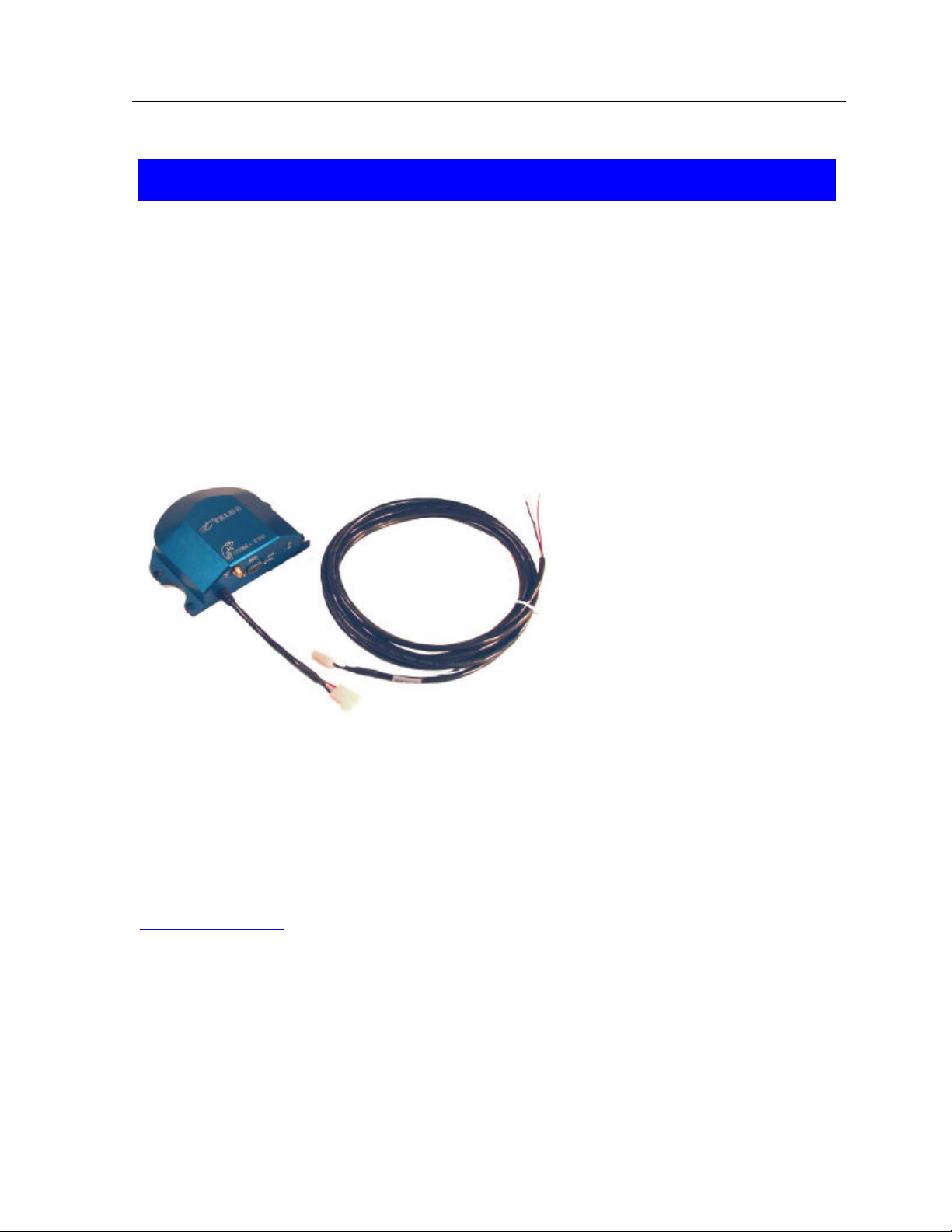
5.1 CTM-110 Telus bundle
CTM-110 Modem
The modem is pre-configured for Telus operation and cannot be activated on another network
except through a roaming agreement. The label on the modem base provides carrier
configuration, regulatory information and the modems Electronic Serial Number (ESN).
Power cable
A standard 4m (12’) length Cable Is provided. Longer lengths are available – contact your dealer
or Cypress Solutions Inc.
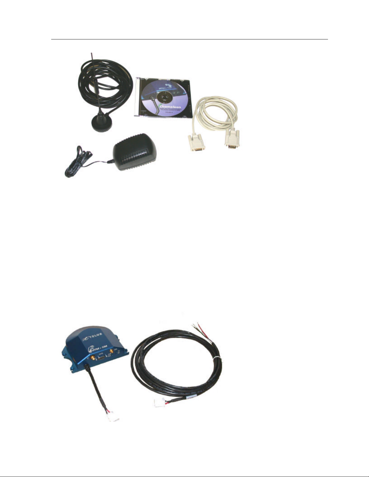
Serial data cable
DB9 male (modem end) to DB9 Female (PC end), 2m (6’) length.
CD-ROM
This contains the Chameleon Controller Software application for configuration and control of
the CTM-110. It also contains the Windows driver for the modem along with this installation
and operation manual.
Check the Cypress Solutions web site for updates to the Chameleon Controller Software
www.cypress.bc.ca
Cell Antenna
Dual band (800MHz and 1900MHz bands) magnetic mount 3dBi whip antenna with 3m (10’)
cable fitted with SMA connector.
AC/DC power supply
120VAC, 50/60Hz to 12VDC power supply to power the Chameleon modem when not
powered directly from a 12 or 24 volt source.
Page 7
Page 8
CTM-110/120 Installation & Operation Manual
1702-0037 Rev 3.2
5.2 CTM-120 Telus bundle
CTM-120 Modem
The modem is pre-configured for Telus operation and cannot be activated on another network
except through a roaming agreement. The label on the modem base provides carrier
configuration, regulatory information and the modems Electronic Serial Number (ESN).
Power cable
A standard 4m (12’) length Cable Is provided. Longer lengths are available – contact your dealer
or Cypress Solutions Inc.
Serial data cable
DB9 male (modem end) to DB9 Female (PC end), 2m (6’) length.
Page 8
Page 9

CTM-110/120 Installation & Operation Manual
1702-0037 Rev 3.2
CD-ROM
This contains the Chameleon Controller Software application for configuration and control of
the CTM-120. It also contains the Windows driver for the modem along with this installation
and operation manual.
Check the Cypress Solutions web site for updates to the Chameleon Controller Software
www.cypress.bc.ca
Cell Antenna
Dual band (800MHz and 1900MHz bands) magnetic mount 3dBi whip antenna with 3m (10’)
cable fitted with SMA connector.
AC/DC power supply
120VAC, 50/60Hz to 12VDC power supply to power the Chameleon modem when not
powered directly from a 12 or 24 volt source.
GPS antenna
A magnetic mount low profile antenna with 5 metre (16’) coax cable and MCX connector for
direct connection to the CTM-120 modem.
Page 9
Page 10

CTM-110/120 Installation & Operation Manual
1702-0037 Rev 3.2
6 Physical Installation
6.1 Mounting the CTM-110/120
The CTM-110/120 is provided with four mounting locations in its base. These may be
used to screw or bolt the device to a suitable surface. If the installation location is subject
to shock or vibration forces in excess of the modem’s specification then suitable
mounting must be arranged to alleviate these forces. The modem ships with 5 adhesive
backed rubber feet installed on the bottom mounting plate.
Page 10
Page 11

CTM-110/120 Installation & Operation Manual
1702-0037 Rev 3.2
6.1.1 Mounting Area and Keep out region.
6.2 Connecting the power cable
The power cable has three wires:
Red +V supply (+9 to +32VDC)
Black 0V return
White Standby (+V for operation, 0V or floating
for standby)
A 5Amp “slow-blow” fuse is recommended in the +V supply line.
The operate/standby switch may, for example, be the accessory position on a vehicle
ignition switch.
Refer to the operation notes for details of operation/standby modes.
Page 11
Page 12

CTM-110/120 Installation & Operation Manual
1702-0037 Rev 3.2
6.3 Connecting the serial data cable
The modem serial data port is a standard DB9 female connector configured as Data
Communication Equipment (DCE) and is wired as per the table below.
DB9
Pin
1 DCD Data Carrier Detect Modem à PC
2 RxD Received Data (by DTE) Modem à PC
3 TxD Transmitted Data (by DTE) PC à Modem
4 DTR Data Terminal Ready PC à Modem
5 GND Signal Ground
6 DSR Data Set Ready Modem à PC
7 RTS Request To Send PC à Modem
8 CTS Clear To Send Modem à PC
9 RI Ring Indicator Modem à PC
The DTR signal (pin 4) is used for modem operation/standby control - refer to the
operation notes for details.
Serial data ports on most computer equipment are configured as Data Terminal
Equipment (DTE) with a DB9 male connector. The serial data cable supplied with the
CTM-110/120 will allow direct connection of the modem to most computer and
terminal equipment. In some cases it may be necessary to insert a “null modem” or
“gender changer” in the serial data line in order to correctly connect between the
devices.
Signal Name Direction
6.4 Mounting and attaching the cell antenna
The antenna used with the CTM-110/120 must be a dual band type suitable for
operation on both the 800MHz Cellular and 1900MHz PCS bands. For regulatory
purposes the antenna must have a gain rating of less than 9dBi on each band. For
optimum performance the antenna should be mounted in a vertical orientation as high
up as possible and with clear line of sight in all directions. For regulatory purposes it
must be mounted in such a position as to maintain a separation distance from any
person of at least 20cm (8”).
The modem antenna connector is a standard SMA female type that requires the antenna
cable to use a male SMA connector.
6.5 Mounting and attaching the GPS antenna
The antenna used with the CTM-120 must be an active type with gain of at least 26dB
and requiring a 3.3 volt dc supply provided directly by the modem over the coax cable.
The antenna provided is a magnetic mount type for installation typically on an upper
horizontal surface of a vehicle with a clear 360 degree view of the sky.
The GPS antenna connector is a standard MCX type that requires the GPS antenna
cable to use a MCX plug connector.
Page 12
Page 13
CTM-110/120 Installation & Operation Manual
1702-0037 Rev 3.2
7 Software Installation
7.1 STEP 1 - Installing the Chameleon Controller Software
The Chameleon Controller Software is designed for operation with Windows XP, and
2000. It provides tools to configure the CTM-110/120 modem and to setup connections
to the cellular network. For the CTM-120 modem with GPS it also provides an
application to enable the GPS data to be routed to a virtual serial COM port on the local
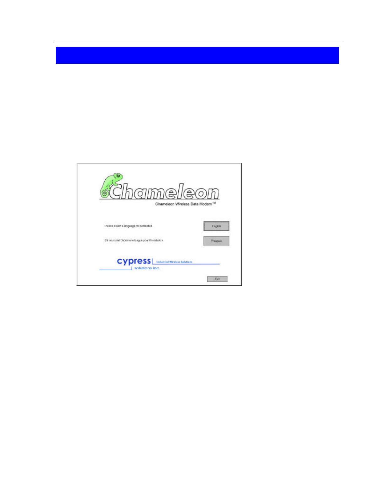
computer so that the position data is available to a mapping application.
To install the Chameleon Controller Software run the file CDstartup.exe from the CDROM. This will invoke the installation wizard:
Select English or French as
the preferred language.
Follow the installation
instructions that appear on the
screen.
At the end of the installation you will be prompted to install the Cypress Solutions
Chameleon modem by following the instructions below for your specific Windows
operating system.
7.2 STEP 2 - Installing the Windows® .inf file
For installations where the CTM-110/120 is to be operated with computers running a
Windows XP or 2000 release operating system it is necessary to install an information
file (.inf) in order that the operating system can successfully find and interface with the
modem. The procedure for each of these operating systems is slightly different.
Page 13
Page 14

CTM-110/120 Installation & Operation Manual
1702-0037 Rev 3.2
7.2.1.1 For Windows XP operating systems
• Select Start > Settings > Control Panel
• Double click on Phone and Modem Options. This will open the phone and modems
properties window.
• Select the Modems tab and click on Add.
• Select don’t detect my modem: I will select it from a list, and click on Next.
• Select Cypress Solutions Inc from the Manufactures list and select Cypress
Solutions Chameleon Modem in the Models dialogue box. Click on Next.
• Select Selected Ports and highlight the communications port on the computer that the
modem is attached to. Click on Next.
• The Digital Signature Not Found dialogue box will then appear warning you that you
are about to install a driver that does not contain a Microsoft digital signature. Click on
Continue Anyway if you wish to continue.
• Click on Finish.
• Click on OK to close the Modems window and then close the Control Panel window.
The Chameleon CDMA modem driver is now installed and ready for use by Windows XP
programs including the Cypress Solutions Chameleon Controller.
Page 14
Page 15

CTM-110/120 Installation & Operation Manual
1702-0037 Rev 3.2
7.2.1.2 For Windows 2000 Operating Systems
• Select Start > Settings > Control Panel
• Double click on Phone and Modem Options. This will open the modems properties
window.
• Select the Modems tab from top of window and click on Add.
• The Add/Remove Hardware Wizard will appear.
• Select don’t detect my modem; I will select if from the list, box and click Next.
• Select Cypress Solutions Inc from the Manufactures list and select Cypress
Solutions Chameleon Modem in the Models dialogue box. Click on Next.
• Select the communications port on the computer that the modem is attached to. Click
on Next.
• Click on Finish.
• Close the Phone and Modem Options window and close the Control Panel window.
The Chameleon CDMA modem driver is now installed and ready for use by Windows 2000
programs including the Cypress Solutions Chameleon Controller.
Page 15
Page 16

CTM-110/120 Installation & Operation Manual
1702-0037 Rev 3.2
8 Operation
8.1 Automatic power control
The CTM-110 Chameleon modem has a low power mode that shuts down all
unnecessary circuits when the modem is not in use but will automatically power up when
it detects user action.
The supply voltage must be at least 8VDC for the CTM-110 to operate. Below this level
the modem will enter low power standby mode.
Operation mode is entered when the modem detects that the RS232 port is active (DTR
going active is used for this)
AND
the standby signal is greater than 9VDC.
With these two conditions met the CTM-110 modem will enter operating mode in 10
seconds. In operating mode the power LED will be on solid.
Standby mode is entered when the modem detects that the RS232 port is inactive (DTR
going inactive is used for this)
AND
the standby signal is less than 9VDC (connected to 0V or disconnected).
With these two conditions met the CTM-110 modem will enter standby mode in 5
seconds. In standby mode the power LED will flash slowly.
8.2 Manual power control
The CTM110 modem can be manually put into low power standby mode at any time by
pressing and holding for at least one second the standby button which is located inside the
front panel (use a straightened paper clip to access it through the hole).
Pressing and holding the standby button when the CTM-110 modem is in low power
standby mode will put it into operating mode – but note that if either the RS232 port is
inactive OR the standby signal is less than 9VDC, then the CTM-110 will automatically
enter low power standby mode again after 5 seconds!
Page 16
Page 17

CTM-110/120 Installation & Operation Manual
1702-0037 Rev 3.2
8.3 Panel LED Indicators
There are four LED indicators on the CTM-110 and CTM-120 panel. These are used to
show the status and operation of the modem.
PWR This LED shows the power status of the modem:
On solid = the modem is on and able to connect
Flash quickly = the modem is shutting down
Flash slowly = the modem is in standby mode
Off = the modem has no power connected
CELL This LED shows the status of the modem on the CDMA network:
Flashing = the modem is attempting to register on the network
On solid = the modem has registered on the network
TX This LED shows that data is being transmitted:
Off = no data is being transmitted
On or flashing = data is being transmitter
(Combined with RX on the CTM-120)
RX This LED shows that data is being received:
Off = no data is being received
On or flashing = data is being received
GPS (CTM-120 only) This LED shows the status of the GPS module:
Flashing = the GPS module is obtaining a position fix
On solid = the GPS module has obtained a valid position
8.4 Carrier Activation Wizard
The first time the Chameleon Controller Software is run with a new CTM-110/120 modem it
will invoke the Activation Wizard. Prior to running the software it is necessary to obtain an
account from Telus Mobility or your dealer – you will be provided with a 6 digit “lock code”
along with the modems telephone number.
Run the Chameleon Controller Software by double clicking on the Chameleon Icon that was
placed on the desktop during the software installation. Select the serial COM port that the
modem is connected to - this question may be suppressed in future by checking the box don’t
tell me about this again.
The Modem Activation Wizard will start:
Enter the 6 digit lock code and the 10
digit telephone number as provided
by Telus. Click Next and follow the
instructions to complete the modem
activation.
Page 17
Page 18

CTM-110/120 Installation & Operation Manual
1702-0037 Rev 3.2
8.5 Chameleon Controller Software Features
The Chameleon Controller Software provides a number of features to configure the modem and
the Windows operating system ready for connecting to the Internet using the Telus 1x network.
It also provides utilities to assist with modem operating configuration and diagnostics.
These features are all accessed from the Chameleon Controller Software application.
8.5.1 Make a new network connection
From the Tools menu select Connection Settings:
Click on Add and follow the
instructions to make a new network
connection:
For a TELUS Mobility 1x connection
the telephone number is #777.
For a TELUS Mobility qnc
connection the telephone number is
#888.
When the new connection has been
setup, enter the user name and
password for this modem and
connection:
For a 1x connection the user name
will be
Phone number@1x.telusmobility.com
and the password will be the ESN as
given on the base of the modem:
099xxxxxxxx
For a qnc connection the user name
will be qnc and the password will be
qnc.
Select Save User Name and Password if you wish these to be remembered by the software for
future use.
To make this your current connection make sure it is selected from the list if there are more than
one connection. Save the connection settings by clicking on OK.
Page 18
Page 19

CTM-110/120 Installation & Operation Manual
1702-0037 Rev 3.2
To connect to the current default connection simply click Connect on the Chameleon
Controller application.
Hint – holding the cursor over the Connect button will tell you which is the current default
connection.
The connection progress will be displayed:
Dialing >> Verifying User Name and Password >> Connected
During the network connection the modem icon will be present in the bottom right system tray
of your desktop. Selecting this icon will show the transmitted and received bytes for this session.
8.5.2 Configure GPS Operation (CTM120 only)
The operation of the internal GPS feature may be configured from the Chameleon Controller
Software application.
From the Tools menu select GPS Configuration:
The GPS position information may be
sent to a remote location over the wireless
connection and over the local serial
connection to the host computer. Each of
these connections may be independently
configured. Data is sent as a $GPGLL
NMEA 0183 sentence.
The local GPS reporting may be enabled
either for this session only or for this and
all future sessions. The GPS update rate
may be set to a value from once per
second, to once per 3600 seconds. GPS
data is sent as a UDP packet to port 5005
of the local host PC. The Chameleon
Controller Software application provides
an automatic utility which makes this data
available on a virtual COM port in the
computer which may be accessed by
standard mapping software applications.
When the remote connection is enabled it must have a remote IP address and port number
configured. This will be the remote server that will accept this GPS data and allow tracking of
the vehicle or equipment in which the modem is installed. The GPS update rate may be set to a
value from once per second, to once per 3600 seconds.
Page 19
Page 20

CTM-110/120 Installation & Operation Manual
1702-0037 Rev 3.2
8.5.3 Checking the modem Status
Prior to initiating a connection to the network the Chameleon Modem status may be checked.
From the Tools menu select Modem Status:
The Modem Info box shows the modems Electronic Serial
Number (ESN) and factory serial Number (FSN). The current
status of the local CDMA network which the modem is seeing
is reported.
The RSSI value is the modems received signal strength.
The GPS Info box is not used in this release of the Chameleon
Controller Software.
8.5.4 The Terminal Services Window
The Chameleon Controller Software provides the ability to send and receive AT commands
directly to the modem. From the Tools menu select Terminal. Type the required AT command
in the command line window and click on Send. The modem’s response will be displayed in the
response window. The AT command session may be logged to a text file if required.
8.6 Using AT commands to control the CTM-110/120
The CTM-110/120 CDMA modem supports the full AT command set for wireless data
modems. This command set can be used to configure, control, and troubleshoot the
modem.
The Chameleon Controller Software Terminal tool may be used to send AT commands
to the modem and display responses. Alternatively, most terminal emulation programs
such as Windows HyperTerminal can be used to access the CTM-110/120 with AT
commands. Terminal configuration parameters are:
Data rate 115,200 baud
Data bits 8
Parity None
Stop bits 1
Flow control Hardware
The set of AT commands available for the CTM-110/120 CDMA modem can be found
in the Sierra Wireless CDMA AT command reference document available at:
http://www.sierrawireless.com/ProductsOrdering/documents/2130184.pdf
Page 20
Page 21

CTM-110/120 Installation & Operation Manual
1702-0037 Rev 3.2
9 Trouble shooting
Situation The power LED is flashing slowly and I can’t communicate with the
modem.
Solution: The modem is in low power standby mode. Make sure that the standby
signal is connected to greater than 9VDC AND the RS232 port is active.
Situation: The USB to serial converter isn’t working.
Solution: Make sure that the CTM-110/120 modem has been installed in Windows
to use the same comms. port as that used by the USB to serial converter.
Situation: DUN makes a connection but no Internet applications work.
Solution: Make sure that any firewall clients running on your computer have been
disabled (especially if you use your computer in an office LAN
environment).
Situation: How do I check to see if my modem is registered on the network?
Solution: Use the Chameleon Controller software and from the Tools menu select
Modem Status. This provides the following information:
Current band (PCS or CDMA)
Current channel
SID
NID
Modem temperature in degrees Celsius
Pilot acquired (or not)
Modem registered (or not)
Alternatively, from the Tools menu select Terminal and enter the
command AT!STATUS
Situation: I need to find the ESN of the modem but I can’t access the label on its
base.
Solution: Use the Chameleon Controller software and from the Tools menu select
Modem Status. This will return the modems ESN in an 11 digit decimal
format.
Alternatively, from the Tools menu select Terminal and enter the
command AT+GSN. This will return the modems ESN in an 8 digit
hexadecimal format. Convert this to decimal format by separating the
hex number into two parts prior to performing the conversion:
hh-hhhhhh
.
Page 21
Page 22

CTM-110/120 Installation & Operation Manual
1702-0037 Rev 3.2
Situation: How do I find out the CDMA signal strength seen by the modem.
Solution: Use the Chameleon Controller software and from the Tools menu select
Modem Status. This will return information including the current
received signal strength in dBm as seen by the modem:
-137 = no signal!
<-90 = very poor
-90 to -86 = poor
-85 to -81 = fair
-80 to -76 = good
>-75 = excellent
Alternatively, from the Tools menu select Terminal and enter the
command AT!RSSI?. This will report the current received signal strength
in dBm
For additional service and help with CTM-110/120 CDMA modem installation and operations
please contact:
Cypress Solutions Inc.
Service support group
Phone:
1.877.985.2878
604.985.2878
9.00am to 5.00pm PST
support@cypress.bc.ca
Page 22
Page 23

CTM-110/120 Installation & Operation Manual
1702-0037 Rev 3.2
10 Technical Specifications
The Chameleon range of wireless data modems are subject to regular feature enhancement.
Cellular wireless networks are constantly changing and enhancing their capabilities. In order to
meet these changing needs, Cypress Solutions Inc. reserves the right to modify these product
specifications without notice.
___________________________________________________________________
Approvals
EMC FCC part 15 Class B; ICES-003 Class B
Mobile device FCC CFR 47 part 2.1091; Industry Canada RSS-102
Hazardous Location Class 1 Division 2 Zones A, B, C, D, Temperature rating T4 (–30 to +60C)
________________________________________________________________________________
Temperature
Operating MIL-STD 810F Method 502-II, -30 to +65 Celsius
Storage SAE 1455 4.2.3, -40 to +75 Celsius
________________________________________________________________________________
Humidity
5 to 95%RH SAE 1455 4.2.3, 85-95% RH for five 48hr cycles
__________________________________________________________________________________________
Vibration
5 to 500Hz MIL-STD 810F Method 514.5C
___________________________________________________________________________
Shock
40G, 11msec MIL-STD 810F Method 516-I
__________________________________________________________________________________________
Sealing
IP53 Protection against dust and spray water
__________________________________________________________________________________________
Power Supply
Voltage 9 to 32 VDC
Current 1mA standby, 550mA peak at 12VDC
Projection SAE J1455
__________________________________________________________________________________________
Serial port
Connector DB9, RS232C, DCE configuration
Protocol AT commands & PPP
__________________________________________________________________________________________
RF
800MHz & SMA 50ohm connector
1,900MHz bands +23.5dBm max
__________________________________________________________________________________________
Size
Width 147mm
Depth 115mm (excluding cabling)
Height 41mm
__________________________________________________________________________________________
Weight
700 grams
___________________________________________________________________________
Page 23
 Loading...