

Page 1
int
Int. Service (+49) 6838/907 172
für Service 06838/907 172
for service (+44) 0845 602 4285
pour service 03 87 95 39 28
voor service 020 684 7978
de
en
fr
nl
www.liftmaster.com
Email: info@chamberlain.com
Chamberlain GmbH
Alfred-Nobel-Str.4
66793 Saarwellingen
fr
de
en
cs
el
hu
hr
it
nl
pt
pl
es
Anleitungen – Automatische Torantriebe Modelle LYN300, LYN400, SCS300 Serie
Instructions – Les ouvre-portails automatiques LYN300, LYN400, séries SCS300
Instructions – Automatic Gate Opener Modells LYN300 Series, LYN400 Series,
SCS300 Series
Návody – Automatické pohony bran modely LYN300, LYN400, série SCS300
Instrucciones – Automatismos de puerta automáticos, modelos LYN300, LYN400,
SCS300 de las series
O‰ËÁ›Â˜ – ·˘ЩfiМ·ЩФИ МЛ¯·УИЫМФ› БО·Ъ·˙fiФЪЩ·˜, МФУЩ¤П· LYN300, LYN400,
SCS300 Series
Útmutatók – SCS300-as sorozatba tartozó LYN300-as és LYN400-as
automatikus garázsajtó
Upute – Automatski pogoni vrata, modeli LYN300, LYN400, SCS300 serije
Istruzio ni – Automazioni per cancelli modelli LYN300, LYN400, serie SCS300
Instrukties – Automatische hekaandrijvingen LYN300, LYN400, SCS300 Series
Instruções – Automatismos para portões de garagem das séries LYN300,
LYN400, SCS300
Instrukcje – Automatyczne nap´dy bram modeli serii LYN300, LYN400, SCS300
Инструкция – Автоматические приводы ворот серии моделей LYN300,
LYN400, SCS300
ru
Page 2

0 m
1,0 m
2,0 m
3,0 m
4,0 m
5,0 m
6,0 m
250 kg 180 kg 160 kg 140 kg
Wing Weight
Wing Size
LYN300LYN300
LYN400LYN400
0 m
0.5 m
1.0 m
1.5 m
2.0 m
2.5 m
3.0 m
250 kg 180 kg 160 kg
Wing Weight
Wing Size
SCS300
3.5 m
4.0 m
Page 3

1-de
Inhalt: Allgemeine Hinweise zur Montage
und Nutzung:
Inhaltsangabe: Seite 1
Inhalt d. Kartons: Abbildung
Bevor Sie beginnen: Seite 2
Checkliste: Seite 2
Tortypen/Montagehöhe:
Seite 2, Abbildung A-F
Torsituation:
Seite 2, Abbildung A-F
Anschläge für das Tor:
Seite 2, Abbildung A-F
Montagemaße & Öffnungswinkel
Seite 2-3, Abbildungen A-B
Pfeilerbeschlag/Torbeschlag:
Seite 2-3, Abbildungen A-D
Entriegelung der Antriebsarme:
Seite 3, Abbildung
Montage des Antriebsarme:
Seite 3, Abbildungen A-B
Verkabelung:
Seite 3, Abbildungen
Wartungsarbeiten: Seite 3
Inbetriebnahme: Seite 3
Technische Daten: Seite 3
Ersatzteile: Abbildung
INHALT DES KARTONS
(1) Antrieb LYN & SCS (1/2)
(2) Pfeilerbeschlag LYN & SCS
(3) Schlüssel je Antrieb (2)
(4) Torbeschlag LYN & SCS (1)
(5) Kondensator 230V (1)
(6) Montageanleitung (1)
(7) LYN Bolzen (2) und Ringe (4)
(8) SCS Bolzen (2) und Ringe (2)
(9) SCS Mutter (1) und Scheibe (1)
1
BEGINNEN SIE MIT LESEN DIESER WICHTIGEN SICHERHEITSREGELN
Solche Warnzeichen bedeuten “Vorsicht!”, eine Aufforderung zur Beachtung, da ihre Mißachtung Personen- bzw.
Sachschäden verursachen kann. Bitte lesen Sie diese Warnungen sorgfältig.
Dieser Torantrieb ist so konstruiert und geprüft, daß er bei Installation und Benutzung unter genauer Befolgung der
anschließenden Sicherheitsregeln angemessene Sicherheit bietet.
Die Nichtbeachtung der folgenden Sicherheitsregeln kann ernsthafte Personen- oder Sachschäden verursachen.
1
2
3
3
5
6
7
8
Elektrische Leitungen sind entsprechend den lokalen
Bau- und Elektroinstallationsvorschriften zu verlegen.
Das elektrische Kabel darf nur von einer autorisierten
Elektrofachkraft an ein ordnungsgemäß geerdetes
Netz angeschlossen werden.
Bei der Montage muß ein Einschließen zwischen dem
angetriebenen Teil und den umgebenden Teilen des
Gebäudes (z.B. eine Wand) aufgrund der Öffnungsbewegung
des angetriebenen Teils berücksichtigt werden.
Automatisch gesteuerte Geräte müssen vom Netz
getrennt werden, wenn Wartungsarbeiten wie zum
Beispiel Reinigung ausgeführt werden.
In der festverlegten Installation ist eine Trennvorrichtung vorzusehen, um ein allpoliges Abschalten
mittels Schalter (mind. 3mm Kontaktöffnungsweg) oder
separate Sicherung zu gewährleisten.
Beim Umgang mit Werkzeugen und Kleinteilen
Vorsicht walten lassen und weder Ringe, Uhren noch
lose Kleidungsstücke tragen, wenn Sie Installationsoder Reparaturarbeiten an einem Tor vornehmen.
Stellen Sie sicher, daß Personen, die den Antrieb
montieren, warten oder bedienen diesen Anleitungen
folgen. Bewahren Sie die Anleitung an einem Ort auf, an
dem schnell auf sie zurückgegriffen werden kann.
Entfernen Sie bitte alle am Tor angebrachten Schlösser
um Schaden am Tor zu vermeiden.
Es ist wichtig, das Tor immer gut gangbar zu halten.
Tore die steckenbleiben oder verklemmen, sind
unverzüglich zu reparieren. Versuchen Sie nicht das
Tor selbst zu reparieren. Bestellen Sie dafür einen
Fachmann.
Entfernen Sie zusätzliches Zubehör aus der Nähe von
Kindern. Erlauben Sie Kindern nicht Drucktaster und
Fernbedienungen zu bedienen. Schwere Verletzungen
können durch ein sich schließendes Tor verursacht werden.
Nach der Installation ist zu prüfen, daß der
Mechanismus richtig eingestellt ist und dass der
Antrieb, das Sicherheitssystem und die
Notentriegelung richtig funktioniert.
Der endgültige Schutz vor Quetsch- und Scherstellen
muss nach der Montage des Antriebes mit dem Tor
gewährleistet sein.
Ist ein Gehtor im Tor vorhanden, darf der Antrieb nicht
starten oder weiter laufen, wenn das Tor nicht
ordnungsgemäss geschlossen ist.
4
9
Page 4

2-de
TORSITUATION
Wie weit muß der Flügel geöffnet werden?
90 Grad oder bis 115 Grad. Ein Öffnungswinkel über 115 Grad ist
bedingt möglich, aber nicht empfehlenswert! Begründung: Der
Antrieb läuft immer mit der gleichen Geschwindigkeit. Je weiter das
Tor geöffnet werden muß um so schneller muß sich der Flügel
bewegen. Die Bewegungen werden ruckartiger, Beschläge und Tor
werden dadurch extrem belastet.
Gilt für Antriebe ohne Endschalter: Ein unterschiedlicher
Öffnungswinkel führt dazu, daß der Antrieb, der zuerst sein Ziel
erreicht am Anschlag "brummt" (laufender Motor) und am Tor drückt,
bis der andere Motor ebenfalls seine Endlage erreicht hat (siehe
Abbildungen 3A-F).
Profi Tip: Durch gezielt unterschiedliche A+B Maße (links + rechts)
läßt sich die Zeit des Erreichens am Endanschlag kontrollieren. Die
Beschläge werden aber bei dieser Montageart hoch belastet und es
kann zu einem ruckartigen Lauf des Tores kommen. Diese Methode
ist nur dem erfahrenen Torbauer zu empfehlen.
HINWEIS: Öffnet das Tor zu einer Mauer oder Wand besteht
Einklemmgefahr. Ist der bei geöffnetem Tor übrig bleibende Abstand
unter 200mm, muss dieser Bereich später zusätzlich mittels einer
Lichtschranke oder Kontaktleiste gesichert werden.
ANSCHLÄGE
Ein Drehtor braucht einen festen Anschlag in Tor AUF und Tor
ZU. Anschläge schonen den Antrieb, das Tor und die Beschläge. Ein
Betreiben des Tores ohne feste Endanschläge führt zu einem
schlechten Lauf, ist oft gefährlich und führt zu einem vorzeitigen
Verschleiß und zum Erlöschen der Garantie!
PFEILERBESCHLAG
Der richtige Platz des Pfeilerbeschlags ist entscheidend für die
spätere Funktion der Anlage. Er bestimmt den Abstand des
Drehpunktes des Motors zum Drehpunkt des Tores und somit den
Öffnungswinkel. Man spricht von Maß A und Maß B. Unterschätzen
Sie nicht den Einfluß dieser Maße auf die Funktion und den Lauf.
Versuchen Sie das beste Maß für Ihren Öffnungswinkel unter allen
Umständen und so genau wie möglich zu erreichen. Siehe Tabelle
(Abbildung 3F) für Maße A/B.
Ist der Pfeiler nicht breit genug, muß eine Adapterplatte angefertigt
werden (Abbildung 5B). Ist der Pfeiler zu dick, muß er
ausgenommen (Abbildung 5D) oder das Tor versetzt werden
(Abbildung 5C).
Um optimale Maße zu erreichen, kann es nötig sein, die mitgelieferte
Scharnierplatte zu kürzen oder zu verlängern. Bei neu
anzufertigenden Toren kann, wenn die Torangeln an den Pfeilern
entsprechend montiert werden, Einfluß auf die Maße A und B
genommen werden. Bevor die Anbaumaße endgültig festgelegt
werden, sollte immer geprüft werden, ob der Antrieb beim Schwenken
nicht am Pfeiler anecken könnte.
MONTAGE: Die Kräfte, mit denen sich der Antrieb gegen den Pfeiler
abstützt, sind sehr groß. Meistens ergeben sich schon akzeptable
Einbaumaße, wenn die mitgelieferte Scharnierplatte direkt an den
Pfeiler geschweißt wird. Bei dicken Stein- oder Betonpfosten muss das
Scharnierteil auf eine Trägerplatte geschweißt und so befestigt werden,
dass sich die Dübel im Betrieb nicht lockern können. Besser als Stahloder Kunststoff-Spreizdübel eignen sich hierzu Klebe-Verbundanker, bei
denen ein Gewindestift spannungsfrei im Mauerwerk eingeklebt wird.
Bei gemauerten Pfeilern sollte eine größere Stahlplatte, mehrere Steine
überdeckend, angeschraubt werden, auf die dann die Scharnierplatte
aufgeschweißt werden kann. Gut zur Befestigung eignet sich auch eine
um die Pfeilerkante befestigte Winkelplatte.
ZUBEHÖR TIPP 1: Für runde Pfeiler kann ein Zubehörbeschlag
montiert werden, der das Einstellen des A/B Masses vereinfacht
(Modell 207917).
ZUBEHÖR TIPP 2: Für nach aussen schwingende Tore kann ein
spezieller Beschlag bestellt werden.
BEVOR SIE BEGINNEN
Der Antrieb benötigt an der Seite Platz für Arme und Montage.
Achten Sie bitte darauf, ob dieser zur Verfügung steht. Tore mit
starker Windlast sind mit einem (elektrischen) Schloß zusätzlich zu
sichern!
Es gibt viele Faktoren, die für die Wahl des richtigen Antriebs
entscheidend sind. Ausgehend von einem gut funktionierendem Tor,
stellt das "Anfahren" das Schwierigste dar. Ist das Tor in Bewegung
hat es zumeist einen erheblich geringeren Kraftbedarf.
• Torgrösse: Die Torgrösse ist ein sehr wichtiger Faktor. Wind kann
das Tor bremsen oder es verspannen und den Kraftbedarf stark
erhöhen.
• Torgewicht: Die Angabe Torgewicht stellt nur eine ungefähre
Kenngrösse dar, die sehr stark vom tatsächlichen Bedarf
abweichen kann. Die Funktion ist wichtig.
• Einfluss der Temperatur: Tiefe Außentemperaturen können das
Anfahren erschweren (Bodenveränderungen etc.) oder verhindern.
Hohe Außentemperaturen können den Temperaturschutz (ca.
135°C) früher auslösen (Nur bei 230Volt Antrieben).
• Betriebsfrequenz/Einschaltdauer: 230Volt Antriebe haben eine
maximale Einschaltdauer von ca. 30% (z.B. 30% einer Stunde).
24Volt Antriebe können permanent laufen.
ACHTUNG: 230Volt Antriebe wurden nicht darauf ausgelegt,
dauerhaft an der maximalen Einschaltdauer zu arbeiten
(Dauerbetrieb). Der Antrieb wird zu warm und schaltet ab bis er
wieder die Einschalttemperatur erreicht hat. Die Außentemperatur
und das Tor stellen wichtige Größen für die tatsächliche
Einschaltdauer dar.
CHECKLISTE INSTALLATION – VORBEREITUNGEN
Kontrollieren Sie den Inhalt der Verpackung und lesen Sie die
Anleitung aufmerksam durch. Stellen Sie die einwandfreie
Arbeitsweise Ihrer Torvorrichtung sicher. Das Tor muß gleichmäßig
und stossfrei laufen, es darf an keiner Stelle hängenbleiben. Denken
Sie daran, daß sich der Boden im Winter um einige Zentimeter
heben kann. Um störende Pendelbewegungen zu vermeiden sollte
das Tor stabil und möglichst spielfrei sein. Je leichtgängiger der
Flügel, desto feinfühliger ist die Kraft einzustellen.
Machen Sie sich Notizen welches Material Sie noch benötigen und
besorgen Sie es vor Beginn der Montage. Klebeanker(stabile Dübel),
Schrauben, Anschläge, Kabel, Verteilerdosen, Werkzeuge, etc.
TORTYPEN
Der Tortyp entscheidet über die Montageplatz des Antriebs. Ist der
Anschlag des Tores auf dem Boden sollte der Antrieb ebenfalls
möglichst weit unten montiert werden, damit er das Tor nicht
verdrehen kann. Verwenden sie nur Teile des Rahmens für die
Befestigung.
TYP A, B, C
Bei Stahltoren sollte die Befestigung des Torbeschlags am
Hauptrahmen erfolgen. Ist nicht klar ob der zur Verfügung stehende
Träger stabil genug ist, verstärken Sie ihn.
TYP D, E, F
Bei Holztoren muß der Torbeschlag durchgeschraubt werden. Eine
Platte von der Außenseite wird empfohlen, damit die Befestigung
sich mit der Zeit nicht lockern kann. Dünne Holztore müssen
zusätzlich verstärkt werden, weil Sie sonst der Beanspruchung nicht
standhalten (z.B. Typ F).
2
3
4
5
Page 5

3-de
WARTUNGSARBEITEN
Die Mechanik des Antriebs ist wartungsfrei. Prüfen Sie in
regelmäßigen Abständen (monatlich) den festen Sitz der Beschläge
des Tores und des Antriebs. Entriegeln Sie den Antrieb und testen Sie
die Funktion des Tores. Nur ein leichtgängiges Tor wird auch gut mit
einem Antrieb funktionieren. Ein Antrieb ist kein Ersatz für ein schlecht
funktionierendes Tor.
Bei 24Volt Antrieben siehe auch Anleitung der Steuerung.
TORBESCHLAG
Der Torbeschlag muß waagrecht zum Pfeilerbeschlag montiert
werden. Der Abstand zwischen den Beschlägen wird Einspannmass
genannt. Im geschlossenen Zustand des Tores ist der Antrieb 99%
ausgefahren. Im geöffneten Zustand des Tores ist der Antrieb 1%
ausgefahren. Komplettes EIN oder AUS - fahren des Kolbens im
Betrieb (mit Tor) beschädigt den Antrieb und führt zum Erlöschen der
Garantie! Halten Sie das Einspannmass unter allen Umständen ein!
Bei Stahltoren sollten die Befestigungen angeschweißt oder
durchgeschraubt werden. Beim Durchschrauben sind auf der Rückseite
große Scheiben zu verwenden oder eine Platte.
Bei Holztoren muß die Befestigung durchgeschraubt werden. Eine
Platte von der Außenseite wird ist sehr zu empfehlen, damit die
Befestigung sich nicht lockern kann. Dünne Holztore ohne
Metallrahmen müssen zusätzlich verstärkt werden, weil Sie einer
dauernden Beanspruchung nicht standhalten (z. B. Typ F).
ENTRIEGELUNG
Der Antriebsmechanismus läßt sich entriegeln. Das Tor kann
anschließend von Hand geöffnet und betätigt werden (Stromausfall).
Bei neuen Antrieben wird die Entriegelung manchmal als
schwergängig/ruckend empfunden. Das ist normal und hat keine
Auswirkung auf die Funktion!
Entriegeln: Stecken Sie den Zylinderschlüssel ein und drehen Sie
Ihn um 180 Grad. Anschließend drehen Sie den Entriegelungshebel
ebenfalls um 180 Grad. Fertig.
Verriegeln: Drehen Sie den Hebel nach Hinten. Sobald sich das Tor
bewegt oder der Antrieb läuft verriegelt das Getriebe wieder. Mittels
des Schlosses kann nun der Hebel gegen unbeaufsichtigtes
Entriegeln gesichert werden.
MONTAGE DER ANTRIEBSARME
Entriegeln Sie den Antrieb. Schieben Sie den entriegelten Antrieb auf
die Beschläge und sichern Sie Ihn mit den mitgelieferten Bolzen,
Ringen oder Muttern (Abbildung 7).
Wird am Pfeilerbeschlag das mittlere oder das innere
Befestigungsloch benutzt, muss der Pfeilerbeschlag vor der ersten
Inbetriebnahme gekürzt werden um am Antrieb genügend Freiraum
zu belassen. Eine Missachtung führt zu einem Bruch des Beschlags
am Antrieb! Wird der Antrieb auf den Beschlag geschoben, darf kein
Hammer oder ähnliches benutzt werden.
VERKABELUNG
230VOLT: Das Anschlußkabel ist 4- polig und ca. 80cm lang und
wird in einem Bogen zur Steuerung oder zu einer oberirdisch
angebrachten wasserdichten Verteilerdose geführt. Von der
Verteilerdose erfolgt mittels zulässigem Kabel eine feste Verlegung.
Der Kondensator kann in der Verteilerdose oder in der Steuerung
angeschlossen werden.
Anschluss: Der Kondensator wird zwischen die Klemmen OP und
CL geklemmt. OP und COM ergibt die Drehrichtung A. CL und COM
ergibt die umgekehrte Drehrichtung. Vergessen Sie niemals die
Anlage zu erden (Abbildung 7B).
24VOLT: Das Anschlußkabel ist 6-polig, ca. 80cm lang und wird in
einem Bogen zur Steuerung oder zu einer oberirdisch angebrachten
wasserdichten Verteilerdose geführt. Von der Verteilerdose erfolgt
mittels zulässigem Kabel eine feste Verlegung.
Anschluß: Siehe Anleitung Steuerung.
Kabelfarben: Braun/Grün/Weiss/Gelb=Sensoren
Blau/Rot: 24Volt Motor.
ZUBEHÖR TIPP: Verlängerungskabel LA400-JB40
Beinhaltet:
(1) 12m Kabel mit Klemmen
(1) Verteilerdose IP65
(2) Zugentlastungen PG 13,5
(1) Montagematerial
ERSTE INBETRIEBNAHME
Prüfen Sie im entriegelten Zustand mit der Hand am Tor die Funktion.
Eine elektrische Inbetriebnahme ist nur mit einer geeigneten Steuerung
möglich. die Sie als Zubehör erwerben können. Achten Sie immer
darauf, ob die für die Anlage zutreffenden mechanischen und
elektrischen Sicherheitsvorschriften eingehalten werden.
Ist die Kraft des sich bewegenden Flügels an der Schließkante
höher als 400N müssen zusätzliche Sicherheitseinrichtungen
(Lichtschranke, Kontaktleiste) verwendet werden.
Sicherheitseinrichtungen müssen den Anforderungen
EN60335-2-103 entsprechen.
5
6
7
7
TECHNISCHE DATEN
230Volt
Netzanschluß (Motor)
Motorspannung
Stromaufnahme
Leistungsaufnahme
Kondensator
Max. Torbreite
Max. Torgewicht
Schutzklasse
Anschlusskabel
Axiale Kraft
Laufgeschwindigkeit
Dauerlauf
Temperaturbereich
24Volt
Netzanschluß (Motor)
Motorspannung
Stromaufnahme
Leistungsaufnahme
Max. Torbreite
Max. Torgewicht
Schutzklasse
Kraft (Nominal)
Laufgeschwindigkeit
Öffnungszeit 90
O
Sek.
Temperaturbereich
220 – 240Volt˜/ 50Hz
220-240 Volt
1,2A
280W
6,3μF
2,5m LYN300
4,0m LYN400
3,0m SCS300
250kg
I - IP 44
H07RN-F / 80cm
250N
20mm/s LYN300, SCS300
12mm/s LYN400
4 Minuten
-20
o
C bis + 55oC
220 – 240Volt˜/ 50Hz
24Volt
2A
48W
2,5m LYN300
4,0m LYN400
3,0m SCS300
250kg
I - IP 44
250N
variabel
ca. 12 LYN300
ca. 14 LYN400
ca. 10 SCS300
-20
o
C bis + 55oC
Konformitätserklärung
Automatische Torantriebe Modelle LYN300, LYN400, SCS300 Series
erfüllt die Anforderungen der geltenden
Abschitte der Normenvorschriften EN300220-3 • EN55014 • EN61000-3 • EN60555,
EN60335-1 • ETS 300 683 • EN60335-1: 2002 • EN60335-2-103: 2003 • EN55014-1:
2000 + A1 + A2 • EN55014-2: 2001 • EN61000-3-2: 2000 • EN61000-3-3: 1995 + A1 • EN
301 489-3, V1.3.1 • EN 300 220-3 V1.1.1 • EN 13241-1
sowie die Bestimmungen und sämtliche Ergänzungen
der EU-Vorschriften ..............................................2006/95/EC, 2004/108/EC, 1999/5/EG
Einschlußerklärung
Die automatischen Torantriebe, erfüllen die Bestimmungen der EU-Vorschrift 89/393/EEC
und ihre Ergänzungen, wenn sie gemäß den Anleitungen des Herstellers installiert und
gewartet werden und wenn sie mit einem Tor verwendet werden, das ebenfalls gemäß
Herstelleranleitungen installiert wurde und gewartet wird.
Die Unterzeichnende erklärt hiermit, dass das vorstehend
angegebenne Gerät sowie sämtliches im Handbuch aufgeführtes
Zubehör den oben genannten Vorschriften und Normen entspricht.
B.P.Kelkhoff
Manager, Regulatory Affairs
Chamberlain GmbH
D-66793 Saarwellingen
January, 2008
Page 6

1-fr
Table des matières: Consignes générales de
montage et d'utilisation :
Sommairee : Page 1
Contenu: Figure
Avant de commencer : Page 2
Liste de contrôle : Page 2
Types de portails/hauteur de montage :
Page 2, Figure A-F
Situation du portail :
Page 2, Figure A-F
Butées pour le portail :
Page 2, Figure A-F
Cotes de montage et angle d'ouverture :
Page 2-3, Figure A-B
Ferrures de pilier/Ferrures de portail :
Page 2-3, Figure A-D
Déverrouillage des bras d'entraînement :
Page 3, Figure
Montage des bras d'entraînement :
Page 3, Figure A-B
Câblage :
Page 3, Figure
Travaux de maintenance : Page 3
Mise en Service : Page 3
Caractéristiques techniques : Page 3
Pièces de rechange : Figure
CONTENU
(1) Moteur LYN & SCS (1/2)
(2) Ferrures de pilier LYN & SCS
(3) Clés par ouvre-portail (2)
(4) Ferrures de portail LYN & SCS (1)
(5) Condensateur 230V (1)
(6) Notice de montage (1)
(7) LYN Clavettes (2) et Bagues (4)
(8) SCS Clavettes (2) et Bagues (2)
(9) SCS Ecrou (1) et Rondelles (1)
1
VEUILLEZ TOUT D'ABORD LIRE CES REGLES DE SECURITE IMPORTANTES
Ces pictogrammes appellent à la prudence et ont valeur d'avertissement, car leur non-respect peut entraîner un risque de
blessures corporelles ou de dommages matériels.
Veuillez lire attentivement ces avertissements. Cet ouvre-portail est conçu et testé de manière à offrir un service
raisonnablement sûr sous réserve d'être installé et utilisé strictement selon les règles de sécurité suivantes.
Le non-respect des règles de sécurité suivantes peut provoquer de sérieux dommages corporels ou matériels.
1
2
3
3
5
6
7
8
Les câbles électriques doivent être posés
conformément aux prescriptions locales relatives aux
systèmes et installations électriques. Le câble
électrique doit uniquement être raccordé à un réseau
électrique correctement relié à la terre.
Lors du montage, un confinement entre la pièce entraînée
et les pièces environnantes du bâtiment (par exemple une
paroi) doit être considéré en raison du mouvement
d'ouverture de la pièce entraînée.
Débranchez le courant de l’ouvre-porte de garage avant de
commencer toute réparation ou d’ôter un couvercle.
Dans l’installation fixe, il convient de prévoir un
sectionneur afin de garantir une coupure sur tous les
pôles au moyen d’un interrupteur (avec une course
minimale d’ouverture des contacts de 3 mm) ou un
fusible séparé.
Une prudence particulière s'impose lors de l'utilisation
d'outils et de petites pièces. Ne pas porter de bagues,
de montres ou de vêtements amples lors des travaux
de montage ou de réparation d'un portail.
S'assurer que les personnes qui assurent le montage
ou la maintenance ainsi que celles qui utilisent l'ouvreportail respectent les présentes instructions. Conserver
ces instructions de sorte à pouvoir les retrouver rapidement.
Déposer toutes les serrures montées sur le portail afin
d'éviter d'endommager ce dernier.
Il est important que le portail reste toujours
parfaitement opérationnel. Tout portail qui bloque ou
reste coincé doit être immédiatement réparé. Ne pas
essayer de le réparer soi-même, mais faire appel à un
spécialiste.
Tenir tous les accessoires supplémentaires hors de portée
des enfants. Ne pas laisser les enfants utiliser les boutons
ou les télécommandes. La fermeture d'un portail peut
provoquer de sérieuses blessures.
Après installation, il convient de vérifier l'ajustement
correct du mécanisme ainsi que le bon
fonctionnement de l'entraînement, du système de
sécurité et du dispositif de déverrouillage d'urgence
(le cas échéant).
La protection absolue des zones de pincement et de
cisaillement doit être garantie une fois le montage de
l'entraînement sur le portail terminé.
Si le portail possède un portillon pour piétons,
l'entraînement ne doit pas se déclencher ou continuer à
fonctionner si le portillon n'est pas fermé correctement.
4
9
Page 7

2-fr
SITUATION DU PORTAIL
Quel angle d'ouverture pour le portail ?
90 degrés ou 115 degrés. Un angle d'ouverture supérieur à 115
degrés est éventuellement possible, mais n'est pas recommandé.
Motif: l'entraînement tourne toujours à la même vitesse. Plus l'angle
d'ouverture du portail est important, et plus le battant doit se déplacer
rapidement. Les mouvements deviennent saccadés, ce qui expose
les ferrures et le portail à des sollicitations extrêmes.
S'applique aux ouvre-portails sans fins de course : En cas
d'angles d'ouverture différents des deux battants, l'entraînement qui
a atteint le premier sa position finale continue à "ronronner" en butée
(le moteur tourne) et à repousser le battant jusqu'à ce que l'autre
moteur ait lui aussi atteint sa position de fin de course (voir figures
3A-F).
Conseil de professionnel: le choix délibéré de cotes A+ B (gauche
+ droite) différentes permet de contrôler le moment d'arrivée en
butée finale. Toutefois, ce type de montage sollicite fortement les
ferrures et peut entraîner un mouvement saccadé du portail. Cette
méthode est réservée aux installateurs expérimentés.
NOTA : Si le portail s'ouvre contre une cloison ou un mur, il existe un
risque de coincement potentiellement dangereux. Si la distance
restante lorsque le portail est ouvert est inférieure à 200 mm, cette
zone doit être ultérieurement protégée en plus au moyen d'une
barrière photoélectrique ou d'une réglette de contacts.
BUTEES
Un portail pivotant nécessite une butée fixe en position portail
OUVERT et portail FERME. Les butées permettent de ménager
l'entraînement, le portail et les ferrures. L'utilisation du portail sans
butées de fin de course définies entraîne un fonctionnement
déficient, souvent dangereux, une usure prématurée ainsi que
l'extinction de la garantie!
FERRURES DE PILIERS
Le choix du bon emplacement de la ferrure de pilier est décisif
pour le fonctionnement ultérieur de l'installation. Il détermine la
distance entre le point de rotation du moteur et celui du portail, et
donc l'angle d'ouverture. On parle de cote A et de cote B. Il ne faut
pas sous-estimer l'importance de cette cote sur le bon
fonctionnement et la qualité du mouvement. Il faut essayer de
déterminer la cote optimale pour votre angle d'ouverture dans toutes
les circonstances et de l'atteindre aussi précisément que possible.
Voir tableau (figure 3F) pour les cotes A/B.
Si le pilier n'est pas assez large, il faut fabriquer une plaque
adaptable (figure 5B). Si le pilier est trop épais, il faut réaliser un
évidement (figure 5D) ou déplacer le portail (figure 5C).
Pour atteindre des cotes optimales, il peut s'avérer nécessaire de
raccourcir ou de rallonger la plaque de charnière fournie. Lors de la
construction d'un nouveau portail, il est possible de jouer sur les
cotes A et B lorsque les gonds du portail sont montés de manière
correspondante sur les piliers. Avant de fixer définitivement les cotes
de montage, vérifier systématiquement que l'entraînement ne cogne
pas contre le pilier lors du basculement.
MONTAGE: les forces exercées par l'entraînement sur le pilier sont
très élevées. En général, on peut déjà atteindre des cotes de montage
acceptables en soudant directement sur le pilier la plaque de charnière
fournie. Dans le cas de piliers épais en pierre ou en béton, il faut
souder la pièce de charnière sur une plaque-support et la fixer de sorte
que les chevilles ne risquent pas de se détacher lors du
fonctionnement. A cet effet, il vaut mieux préférer aux chevilles en acier
ou en plastique des systèmes d'ancrage composite à coller, avec une
tige filetée collée sans précontrainte dans la maçonnerie. Dans le cas
des piliers en maçonnerie, il conviendrait de visser une grande plaque
en acier débordant sur plusieurs pierres et sur laquelle la plaque de
charnière peut ensuite être soudée. Une autre bonne solution consiste
à utiliser une plaque d'équerre fixée sur le pilier.
ACCESSOIRES, CONSEIL 1 : En cas de piliers ronds, le programme
d'accessoires comprend une ferrure qui permet de simplifier le réglage
de la cote A/B (modèle 207917).
ACCESSOIRES, CONSEIL 2 : Pour des portails battants ouvrant vers
l'extérieur, il est possible de commande une ferrure spéciale.
AVANT DE COMMENCER
L'ouvre-portail nécessite un dégagement latéral suffisant pour les
mouvements des bras et pour le montage. S'assurer que l'on
dispose de l'espace nécessaire. Les portails présentant une charge
en torsion élevée doivent être dotés en supplément d'une serrure
(électrique) à titre de sécurité!
Le choix du bon automatisme de portail dépend d'un grand nombre
de facteurs. Partant d'un portail en bon état de fonctionnement, le
"démarrage" est l'opération la plus difficile. Une fois le portail en
mouvement, la force nécessaire est en général nettement moins
élevée.
• Taille du portail : la taille du portail est un facteur très important.
Le vent peut le freiner ou le tordre et donc augmenter fortement la
force nécessaire.
• Poids du portail : le facteur poids n'est qu'une grandeur purement
indicative et susceptible de différer très fortement des besoins
effectifs. Le fonctionnement est le facteur important.
• Influence de la température : des températures extérieures très
basses peuvent freiner ou même empêcher le démarrage
(modifications du sol, etc.). Des températures extérieures très
élevées peuvent provoquer un déclenchement prématuré du
dispositif de protection thermique (env. 135 °C) (uniquement pour
ouvre-portails 230 V).
• Fréquence / durée d'utilisation : le facteur de marche maximal
des mécanismes d'ouvre-portails est de l'ordre de 30 % (p. ex.
30 % d'une heure). Les ouvre-portails 24 Volt peuvent fonctionner
en permanence.
ATTENTION : Les ouvre-portails 230 Volt ne sont pas conçus pour
fonctionner en permanence à la valeur maximale du facteur de
marche (marche en continu). L'entraînement surchauffe et se
désactive jusqu'à son retour à la température de mise en marche.
La température extérieure et le type de portail sont des facteurs
importants pour le facteur de marche effectif.
LISTE DE CONTROLE - PREPARATIFS
Contrôler le contenu de l'emballage et lire attentivement les
présentes instructions. S'assurer du parfait fonctionnement de votre
système de portail. Le portail doit pivoter de manière régulière, sans
à-coups, et ne coincer nulle part. Tenir compte du fait que le sol peut
être rehaussé de quelques centimètres en hiver. Afin d'éviter tout
mouvement pendulaire gênant, le portail doit être stable et présenter
un jeu aussi faible que possible. Plus le battant pivote en douceur, et
plus la force devra être réglée avec précision.
Faire une liste du matériel qui sera nécessaire et préparer ce matériel
avant de commencer le montage. Ancrages à coller (chevilles solides),
vis, butées, câbles, boîtes de dérivation, outils, etc.
TYPES DE PORTAILS
Le type de portail est décisif pour l'emplacement de montage de
l'entraînement. Si la butée du portail se trouve au sol, l'entraînement
devra également être monté le plus bas possible afin d'éviter de
tordre le portail. Utiliser exclusivement des éléments du cadre pour la
fixation.
TYPES A, B, C
Dans le cas des portails en fer, la fixation de la ferrure du portail doit
s'effectuer sur le cadre principal. En cas de doutes quant à la solidité du
support existant, prévoir de le renforcer.
TYPES D, E, F
Dans le cas des portails en bois, la fixation de la ferrure doit
traverser l'épaisseur du bois. Il est recommandé de prévoir une
plaque sur la face extérieure, afin d'empêcher tout risque de
desserrage de la fixation au fil du temps. Pour les portails de faible
épaisseur, prévoir des renforts supplémentaires, sinon ils ne
résisteraient pas à la sollicitation (p. ex. type F).
2
3
4
5
Page 8

3-fr
TRAVAUX DE MAINTENANCE
Le mécanisme de l'ouvre-portail ne nécessite pas d'entretien. Contrôler
régulièrement (une fois par mois) la bonne fixation des ferrures du
portail et de l'ouvre-portail. Déverrouiller l'ouvre-portail et tester le
fonctionnement du portail. Seul un portail manoeuvrant en douceur
pourra fonctionner correctement en liaison avec ouvre-portail. Le
montage d'un ouvre-portail n'est pas une solution pour remédier à un
portail fonctionnant mal.
Pour les ouvre-portails 24 Volt, se reporter aussi à la notice de la
commande.
FERRURES DE PORTAIL
La ferrure de portail doit être montée horizontalement par rapport à la
ferrure de pilier. La distance entre les ferrures est appelée cote de
fixation. En position fermée du portail, l'entraînement est sorti à 99 %.
En position ouverte du portail, l'entraînement est sorti à 1 %. Une
RENTREE ou SORTIE complète du piston en service (avec le portail)
endommage l'entraînement et conduit à l'extinction de la garantie !
Respecter systématiquement la cote de fixation ! Cotes, voir fig. 5A.
Dans le cas des portails en fer, les fixations doivent être soudées ou
montées avec des vis traversant l'épaisseur du portail. Dans ce cas,
utiliser de grosses rondelles ou une plaque au dos du portail. Dans le
cas des portails en bois, la fixation doit traverser l'épaisseur du bois. Il
est fortement recommandé de prévoir une plaque sur la face extérieure,
afin d'empêcher tout risque de desserrage de la fixation. Pour les
portails en bois ou les cadres métalliques de faible épaisseur, prévoir
des renforts, sinon ils ne résisteraient pas à la sollicitation (p. ex. type F).
DEVERROUILLAGE
Le mécanisme d'entraînement peut être déverrouillé. Le portail peut
ensuite être ouvert et actionné à la main (en cas de coupure de
courant). Dans le cas des ouvre-portails neufs, le déverrouillage est
parfois jugé difficile à manoeuvrer / source d'à-coups. Ceci est
normal et n'a aucun effet sur la fonction !
Déverrouillage: Engager la clé et la tourner de 180°. Tourner
ensuite le levier de déverrouillage de 180°. Fin des opérations.
Verrouillage: Tourner le levier vers l'arrière. Dès que le portail se
déplace ou que l'entraînement tourne, le mécanisme se reverrouille. La
serrure permet ensuite d'empêcher tout déverrouillage intempestif.
MONTAGE DES BRAS D'ENTRAINEMENT
Déverrouiller l'entraînement. Repousser l'entraînement déverrouillé
sur les ferrures et le bloquer à l'aide des goujons et des bagues
fournis (figure 7).
Si vous utilisez le trou central ou intérieur de la plaque-charnière
pour monter la ferrure de fixation du montant, vous DEVEZ couper la
partie restante de la plaque-charnière avant la mise en service du
bras. La non-réalisation de cette opération provoquera
l'endommagement de la ferrure de fixation. N'utilisez pas de marteau
lors du montage de l'actionneur sur la plaque-charnière.
CABLAGE
230 VOLT : Le câble de raccordement comporte 4 pôles et mesure
environ 80 cm de long. Il se monte en prévoyant un coude par
rapport à la commande ou vers une boîte de dérivation étanche
montée au-dessus du niveau du sol. La pose fixe s'effectue depuis la
boîte de dérivation au moyen d'un câble agréé. Le condensateur
peut être raccordé dans la boîte de dérivation ou dans la commande.
Raccordement: le condensateur se monte entre les bornes CL et
OP. Le branchement entre CL et COM détermine le sens de rotation
A. Le branchement entre l'autre borne OP et COM détermine le sens
de rotation inverse. Ne surtout pas oublier de mettre l'installation à la
terre (figure 7B).
24 VOLT : Le câble de raccordement comporte 6 pôles et mesure
env. 80 cm de long. Il sera posé en formant un coude vers la
commande ou vers une boîte de dérivation étanche montée en
saillie. La pose à demeure s'effectue depuis la boîte de dérivation au
moyen du câble autorisé.
Raccordement : voir instructions de la commande.
Couleurs des câbles : marron/vert/blanc/jaune = capteurs
bleu/rouge : moteur 24 Volt.
ACCESSOIRE RECOMMANDE: câble de rallonge LA400-JB40
comprend :
(1) 12 m de câble avec bornes
(1) Boite de dérivation IP65
(2) Décharges de traction PG 13,5
(1) Matériel de montage
MISE EN SERVICE INITIALE
L'ouvre-portail étant déverrouillé, contrôler à la main le fonctionnement
du portail. Une mise en service électrique n'est possible qu'en liaison
avec une commande appropriée que vous pouvez acheter en tant
qu'accessoire. Veiller systématiquement à respecter les prescriptions
de sécurité mécaniques et électriques concernant l'installation.
Si la force du portail en mouvement est supérieure à 400 N au
niveau de l'arête de fermeture, il est alors nécessaire d'utiliser des
dispositifs de sécurité supplémentaires (barrière photoélectrique,
réglette de contacts).
5
6
7
7
CARACTÉRISTIQUES TECHNIQUES
230 Volt
Raccordement secteur (moteur)
Tension moteur
Consommation
Puissance absorbée
Condensateur
Largeur maxi du portail
Poids maxi du portail
Classe
Câble de raccordement
Force axiale
Vitesse de marche
Durée de marche
Température de fonctionnement
24 Volt
Raccordement secteur (moteur)
Tension moteur
Consommation
Puissance absorbée
Largeur maxi du portail
Poids maxi du portail
Classe
Force (nominale)
Vitesse de marche
Temps d'ouverture 90° sec..
Température de fonctionnement
220 – 240 Volt˜/ 50Hz
220-240 Volt
1,2A
280W
6,3μF
2,5m LYN300
4,0m LYN400
3,0m SCS300
250kg
I - IP 44
H07RN-F / 80cm
250N
20mm/s LYN300, SCS300
12mm/s LYN400
4 minutes
-20
o
C à + 55oC
220 – 240 Volt˜/ 50Hz
24 Volt
2A
48W
2,5m LYN300
4,0m LYN400
3,0m SCS300
250kg
I - IP 44
250N
variable
env. 12 LYN300
env. 14 LYN400
env. 10 SCS300
-20
o
C à + 55oC
Déclaration de conformité
Les ouvre-portails automatiques modèles LYN300, LYN400, séries SCS300
satisfont aux exigences des sections applicables des normes
EN300220-3 • EN55014 • EN61000-3 • EN60555, EN60335-1 • ETS 300 683 •
EN60335-1: 2002 • EN60335-2-103: 2003 • EN55014-1: 2000 + A1 + A2 • EN55014-2:
2001 • EN61000-3-2: 2000 • EN61000-3-3: 1995 + A1 • EN 301 489-3, V1.3.1 • EN 300
220-3 V1.1.1 • EN 13241-1
ainsi qu'aux dispositions et à tous les compléments
des prescriptions communautaires........................2006/95/EC, 2004/108/EC, 1999/5/EG
Déclaration d'incorporation
Les ouvre-portails automatiques satisfont aux dispositions de la prescription
communautaire 89/393/CEE et de ses compléments, sous réserve d'être installés et
entretenus conformément aux indications du fabricant et d'être utilisés en liaison avec un
portail lui aussi installé et entretenu conformément aux instructions du fabricant.
Le signataire déclare par la présente que l'appareil indiqué ci-dessus ainsi que tous les
accessoires indiqués dans le manuel satisfont aux prescriptions et normes précitées.
B.P.Kelkhoff
Manager, Regulatory Affairs
Chamberlain GmbH
D-66793 Saarwellingen
January, 2008
Page 9
1-en
Contents: General advice on installation and
use:
Contents list: page 1
Content of the carton: figure
Before you begin: page 2
Checklist: page 2
Gate types/installation height:
page 2, figure A-F
Gate configuration:
page 2, figure A-F
Gate stops:
page 2, figure A-F
Assembly measurements and opening
angle: pages 2-3, figures A-B
Post bracket/Gate fixing bracket:
pages 2-3, figures A-D
Release of drive arms:
page 3, figure
Installing the drive arms:
page 3, figure A-B
Wiring: page 3, figure
Maintenance work: page 3
Initial Operation: page 3
Technical Data: page 3
Replacement Parts: figure
CONTENT OF THE CARTON
(1) Motor LYN & SCS (1/2)
(2) Postbracket LYN & SCS
(3) Keys per motor (2)
(4) Gate fixing bracket LYN & SCS (1)
(5) Capacitor 230V (1)
(6) Manual (1)
(7) LYN Clevis pin (2) and rings (4)
(8) SCS Clevis pin (2) and rings (2)
(9) SCS Nut (1) and Washer (1)
1
PLEASE START BY READING THESE IMPORTANT SAFETY RULES • SAVE THESE INSTRUCTIONS
This safety alert symbol means "Caution" - failure to comply with such an instruction involves risk of personal injury or
damage to property. Please read these warnings carefully.
This gate drive mechanism is designed and tested to offer appropriately safe service provided it is installed and operated in
strict accordance with the following safety rules.
Incorrect installation and/or failure to comply with the following instructions may result in serious personal injury or property
damage.
1
2
3
3
5
6
7
8
Installation and wiring must be in compliance with
your local building and electrical installation codes.
Power cables must only be connected to a properly
earthed supply.
Any entrapment possibility by the moving wing between
wing & walls must be secured with safety edges or IRsensors.
Disconnect electric power to the system before making
repairs or removing covers.
A disconnecting device must be provided in the
permanently-wired installation to guarantee all-pole
disconnection by means of a switch (at least 3mm
contact gap) or by a separate fuse.
When using tools and small parts to install or carry
out repair work on a gate exercise caution and do not
wear rings, watches or loose clothing.
Make sure that people who install, maintain or operate
the gate drive follow these instructions. Keep these
instructions in a safe place so that you can refer to them
quickly when you need to.
Please remove any locks fitted to the gate in order to
prevent damage to the gate.
It is important to make sure that the gate always runs
smoothly. Gates which stick or jam must be repaired
immediately. Employ a qualified technician to repair
the gate, never attempt to repair it yourself.
Keep additional accessories away from children. Do not
allow children to play with pushbuttons or remote controls.
A gate can cause serious injuries as it closes.
After the installation a final test of the full function of
the system and the full function of the safety devices
must be done.
The full protection against potential squeeze or
entrappment must work direct when the drive arms are
installed.
This drive cannot be used with a gate incorporating a
wicket door unless the drive cannot be operated with
the wicket door open.
4
9
Page 10

2-en
GATE CONFIGURATION
How far must the gate leaf open?
90 degrees or up to 115 degrees. An opening angle in excess of 115
degrees is possible to a limited extent but is not recommended.
Reason: the drive mechanism always runs at the same speed. The
further the gate has to be opened, the faster the gate leaf must
travel. Movement becomes more erratic and this subjects the fittings
and gate to extreme stresses.
For gates without limit switches: Non-identical opening angles
cause one drive mechanism to reach its destination first, but
continues to run, thereby forcing the gate up against the gate stop
until the other motor eventually reaches its end position (see
figure 3A-F).
Tip for professionals: The time taken to reach the limit stop can be
controlled by deliberately selecting different A and B dimensions (left
+ right). However, this method of installing subjects the fittings to
high stresses and can cause the gate to run erratically. It is
recommended that only experienced gate installers adopt this
method.
IMPORTANT If the gate opens towards a wall, there is a risk of
entrapment. Should the distance between the wall and the open gate
be less than 200 mm, this area must later be secured via a light
barrier or contact strip.
GATE STOPS
A SWING GATE NEEDS A FIXED GATE STOP IN BOTH THE
OPEN AND CLOSE DIRECTIONS. Gate stops save wear and tear
on the drive mechanism, gate and fittings. Operating a gate without
fixed limit stops results in poor performance. It is often dangerous,
leads to premature wear and voids your warranty!
POST FIXING BRACKET
Choosing the correct location for the post fixing bracket has a
decisive impact on the subsequent functioning of the system. It
determines the distance between the motor's centre of motion and
the gate's centre of motion and hence the opening angle. These
dimensions are referred to as dimension A and dimension B. Do
not underestimate the effect that these dimensions have on correct
functioning and running. Try and achieve the best dimension for your
opening angle, as precisely as possible and suitable for all
circumstances. See Table (figure 3F) for dimensions A/B.
If the post is not wide enough, an extension piece must be fitted to it
(figure 5B). If the post is too thick, cut out part of it to make it thinner
(figure 5D)or offset the gate (figure 5C).
To obtain ideal dimensions, it may be necessary to shorten or
lengthen the supplied hinge plate. In the case of gates that are to be
custom made, if the gate hinges are fitted on the posts appropriately,
it is possible to influence dimensions A and B. Before the final
mounting dimensions are determined, you should always check
whether or not there is any possibility that the corner of the drive
mechanism will hit the post as the gate swings.
INSTALLATION: The drive mechanism exerts considerable force
against the post. Usually, acceptable mounting dimensions are
obtained if the supplied hinge plate is welded directly onto the post.
In the case of thick stone or concrete posts, the hinge must be
welded to a base plate and attached so that the plugs cannot work
loose during operation. Heavy-duty plugs where a threaded rod is
bonded into the masonry stress-free are more suitable for this
purpose than steel or plastic straddling plugs. In the case of
brickwork pillars, bolt on a relatively large steel plate that covers
several bricks and then weld the hinge plate to it. An angle plate
attached over the corner of the post is also a good means of fixing
the operators.
ACCESSORY TIP 1: For round posts an accessory fitting can be
mounted that simplifies the setting of the A/B dimension
(model 207917).
ACCESSORY TIP 2: For gates swinging outwards a special fitting can
be ordered.
BEFORE YOU BEGIN
The drive mechanism needs room to the side permitting correct
installation of drive arms. Please make sure that this is available.
Gates affected by high wind loads must also be protected by an
(electric) lock.
There are many factors to consider when choosing the right drive
mechanism. Assuming that a gate functions properly, "startup" is the
most difficult phase, once the gate is in motion, significantly less force
is usually required to move it.
• Gate size: Gate size is a very important factor. Wind can brake or
distort the gate, thereby increasing the amount of force needed to
move it considerably.
• Gate weight: The weight of the gate in not as relevant as the size.
• Effect of temperature: Low outdoor temperatures can make initial
startup more difficult (changes in the ground, etc.) or even prevent
it. High outdoor temperatures along with frequent use can trigger
thermal protection prematurely (approx. 135 ºC). (Only in the case
of 230 volt drives).
• Betriebsfrequenz/Einschaltdauer: 230 volt drive mechanisms
are designed for a maximum operating time (running time) of
approximately 30% (e.g. 30% during any one hour). 24 volt drives
can run permanently.
IMPORTANT: 230 volt drive mechanism is not designed to
operate continuously at its maximum operating time (non-stop
operation). Otherwise the drive mechanism becomes too hot and
switches off until it cools down to the switch-on temperature. The
outdoor temperature and the gate are important parameters that
affect the actual operating time.
INSTALLATION CHECKLIST - PREPARATIONS
Check the carton contents and read the instructions carefully. Make
sure your gate equipment operates perfectly. The gate must run
evenly and smoothly and must not stick at any point. Remember that
the ground level may be several centimeters higher in winter. The
gate must be stable and as free of backlash as possible in order to
prevent any unwanted to and fro movement. The more smoothly the
gate leaf runs, the more sensitive the force adjustment must be.
Note down any materials you still need and obtain them before
starting to install. Heavy-duty plugs, bolts, gate stops, cables,
distribution boxes, tools, etc.
GATE TYPES
The gate type determines the location where the drive mechanism is
installed. If the gate stop is on the ground, the drive mechanism must
also be installed at a height that is as low as possible so that it
cannot twist the gate. Use only parts of the gate frame for fixing
purposes.
TYPE A, B, C
For steel gates, the gate fitting must be attached to the main frame.
If you are uncertain whether the available support is sufficiently
stable, reinforce it.
TYPE D, E, F
In the case of wooden gates, the gate fitting must be through bolted.
It is advisable to fit a plate from the outside so that the fixing
brackets cannot become loose over time. Thin wooden gates must
also be reinforced in order to withstand the stresses encountered
(e.g. type F).
2
3
4
5
Page 11

3-en
MAINTENANCE WORK
The drive mechanism is maintenance free. Check that the gate fittings
and the drive mechanism are securely fixed at regular intervals
(monthly). Release the drive and check that the gate functions properly.
Unless the gate runs smoothly it will not operate correctly with the drive
mechanism. The drive cannot eliminate the problems caused by a gate
that does not work satisfactorily.
24Volt drives: also see owners manual of Electronic Control.
GATE FITTING
The gate fitting must be installed so that it is horizontal relative to the
post bracket. The distance between the gate bracket and post
bracket is referred to as the "arm span". When the gate is closed, the
drive mechanism is 99% extended. When the gate is opened, the
drive mechanism is 1% extended. Fully retracting or extending the
plunger/spindle in operation (with gate) damages the drive
mechanism and voids the warranty. It is absolutely imperative to
comply with the required arm span under all circumstances!
For steel gates, fixings should be welded on or through bolted. When
through bolting the gate, use large washers or a plate on the other
side. The drive mechanism exerts an extremely high force on this joint.
Fixings must be through bolted for wooden gates. Wood deflects
under load and the bolt will become loose. Due to movement caused
by repeated loading, the wood deflects more and more until the gate
no longer closes correctly and has to be repaired.
Fit a reinforcing plate from the outside and one on the inside so that
the wood cannot deflect and the joint cannot become loose.
Thin wooden gates without a metal frame must also be reinforced in
order to withstand continuous stresses (e.g. type F).
RELEASE
The drive mechanism can be released. The gate can then be opened
and operated manually (power failure). With a new drive mechanism,
the release action may sometimes feel stiff/jerky. This is normal and
has no effect on function.
Release: Insert the key in the cylinder lock and turn it 180 degrees.
Then turn the release lever 180 degrees – done!
Engage: Turn the lever glockwise. As soon as the gate moves or the
drive runs, the gear locks again. Use the lock to protect the lever
against unauthorized release.
INSTALLING THE DRIVE ARMS
Release the drive. Push the released drive onto the fittings and
secure it by using the supplied bolts, nuts and rings.
„If the centre or inner hole, on the hinge plate, is used to fix the post
fixing bracket you MUST cut away the remaining section of the hinge
plate before activating the arms. Failure to do so will result in
breaking the fixing bracket“.
Do not use a hammer when you mount the operator on the bracket.
WIRING
230 VOLT: The 4-pole connecting cable is approx. 80 cm long and is
laid in a curve to the controller or a watertight distribution box located
above ground. An approved cable is permanently installed from the
distribution box onwards. The capacitor can be connected inside the
distribution box or in the controller.
Connection: Connect the capacitor across terminals OP and CL.
OP and COM produce rotation direction A. CL and COM produce
reversed direction of rotation. Always remember to earth the
installation (figure 7B).
24 VOLT: The connecting cable has 6 wires, is approx. 80 cm long
and is run in a curve to the control unit or to a watertight distribution
box located above ground. A permanent connection is formed from
the distributor box via an appropriate cable.
Connection: See control unit instructions.
Cable colours: Brown/Green/White/Yellow=sensors
Blue/Red: 24 volt motor.
ACCESSORY TIP: Extension cable LA400-JB40
Contains:
(1) 12m cable with terminals
(1) Distribution box IP65
(2) Strain relief PG 13,5
(1) Mounting material
INIATIAL OPERATION
Check functionality in a disengaged state with the hand on the gate.
Initial electrical operation is only possible with a suitable control unit
that can be purchased as an accessory. Ensure at all times that
mechanical and electrical safety instructions applying to the given
installation are complied with.
Should the force of the moving wing at its closing edge be higher
than 400N , then additional safety facilities (light barrier, contact
strip) must be used. Any safety facilities must comply with the
requirements set out in EN60335-2-103.
5
6
7
7
TECHNICAL DATA
230Volt
Mains supply (Motor)
Motorspannung
Current consumption
Power consumption
Capacitor
Max. gate width
Max. gate weight
Protection Class
Connecting cable
Rated Thrust
Travel Speed
Rated operating time
Temperature
24Volt
Mains supply (Motor)
Motorspannung
Current consumption
Power consumption
Max. gate width
Max. gate weight
Protection Class
Force (nominal)
Travel Speed
Opening time 90° sec.
Temperature
220 – 240Volt˜/ 50Hz
220-240 Volt
1.2A
280W
6.3μF
2.5m LYN300
4.0m LYN400
3.0m SCS300
250kg
I - IP 44
H07RN-F / 80cm
250N
20mm/s LYN300, SCS300
12mm/s LYN400
4 Minuten
-20
o
C up to + 55oC
220 – 240Volt˜/ 50Hz
24Volt
2A
48W
2.5m LYN300
4.0m LYN400
3.0m SCS300
250kg
I - IP 44
250N
variabel
approx. 12 LYN300
approx. 14 LYN400
approx. 10 SCS300
-20
o
C up to + 55oC
Declaration of Conformity
Automatic Gate Opener Models LYN300 Series, LYN400 Series, SCS300 Series
are in conformity to the applicable
sections of StandardsEN300220-3 • EN55014 • EN61000-3 • EN60555, EN60335-1 • ETS
300 683 • EN60335-1: 2002 • EN60335-2-103: 2003 • EN55014-1: 2000 + A1 + A2 •
EN55014-2: 2001 • EN61000-3-2: 2000 • EN61000-3-3: 1995 + A1 • EN 301 489-3,
V1.3.1 • EN 300 220-3 V1.1.1 • EN 13241-1
per the provisions & all amendments
of the EU Directives .............................................2006/95/EC, 2004/108/EC, 1999/5/EG
Declaration of Incorporation
Automatic Gate Opener Models , when installed and maintained according to all the
Manufacturer’s instructions in combination with a Gate, which has also been installed and
maintained according to all the Manufacturer’s instructions, meets the provisions of EU
Directive 89/392/EEC and all amendments.
I, the undersigned, hereby declare that the equipment
specified above and any accessory listed in the manual
conforms to the above Directives and Standards.
B.P.Kelkhoff
Manager, Regulatory Affairs
Chamberlain GmbH
D-66793 Saarwellingen
January, 2008
Page 12

1-cs
Obsah: V‰eobecné pokyny k montáÏi a
pouÏití:
Údaje o obsahu: strana 1
Obsah kartonu: Obrázek
Dfiíve neÏ zaãnete: strana 2
Kontrolní seznam: strana 2
Typy bran/montáÏní v˘‰ka:
strana 2, Obrázek A-F
Umístûní brány:
strana 2, Obrázek A-F
ZaráÏky pro bránu:
strana 2, Obrázek A-F
MontáÏní rozmûry & úhel otevfiení:
strana 2-3, Obrázek A-B
Kování sloupku/kování brány:
strana 2-3, Obrázek A-D
Odblokování hnacích ramen:
strana 3, Obrázek
MontáÏ hnacího ramena:
strana 3, Obrázek A-B
KabeláÏ:
strana 3, Obrázek
ÚdrÏbové práce: strana 3
Uvedení do provozu: strana 3
Technické údaje: strana 3
Náhradní díly: Obrázek
OBSAH KARTONU
(1) Pohon LYN & SCS (1/2)
(2) Kování sloupku LYN & SCS
(3) Klíãe pro kaÏd˘ pohon (2)
(4) Kování brány LYN & SCS (1)
(5) Kondenzátor 230V (1)
(6) MontáÏní návod (1)
(7) LYN âepy (2) a krouÏky (4)
(8) SCS âepy (2) a krouÏky (2)
(9) SCS Matice (1) a podloÏka (1)
1
NEJPRVE SI P¤EôTùTE TATO DÒLEÎITÁ PRAVIDLA BEZPEôNOSTI
Tyto v˘straÏné symboly znamenají "Pozor!", v˘zvu k pozornosti, neboÈ jejich nerespektování by mohlo zpÛsobit po‰kození
lidského zdraví nebo vûcné ‰kody. âtûte prosím tato varování peãlivû.
Tento pohon brány je konstruován a testován tak, Ïe pfii instalaci a pouÏívání zaruãuje pfii pfiesném dodrÏení bezpeãnostních
pravidel pfiimûfienou bezpeãnost.
DÛsledkem nerespektování tûchto bezpeãnostních pravidel mohou b˘t ‰kody na zdraví osob nebo vûcné ‰kody.
3.0
1
2
3
3
5
6
7
8
Elektrická vedení je nutné klást v souladu s místními
stavebními a elektroinstalaãními pfiedpisy. Elektrick˘
kabel smí k fiádnû uzemnûné síti pfiipojit pouze
autorizovan˘ odborník - elektrikáfi.
Pfii montáÏi je nutné zohlednit nebezpeãí sevfiení mezi
pohánûnou ãástí a okolními ãástmi budovy (napfi. stûnou) na
základû otevíracího pohybu pohánûné ãásti.
Pfii provádûní údrÏbov˘ch prací jako je napfiíklad
ãi‰tûní, musejí b˘t automaticky ovládané pfiístroje
odpojené ze sítû.
V pevnû zapojené instalaci je nutné pamatovat na
rozpojovací zafiízení, aby bylo zaruãeno ve v‰ech pólech
odpojování spínaãem (rozevfiení kontaktÛ min. 3 mm)
nebo samostatnou pojistkou.
Pfii manipulaci s náfiadím a drobn˘mi souãástkami
postupujte opatrnû a nenoste prsteny, hodinky, ani
volné obleãení, jestliÏe na bránû provádíte instalaãní
práce nebo opravy.
Zajistûte, aby osoby, které montují, udrÏují a obsluhují
pohon, dodrÏovaly tento návod. UloÏte tento návod na
takovém místû, kde je rychle k dispozici.
OdstraÀte prosím z brány v‰echny namontované
zámky, abyste zabránili jejímu po‰kození.
Je dÛleÏité, aby se brána stále hladce pohybovala.
Brány, které se zaseknou nebo se vzpfiíãí, je nutné
okamÏitû opravit.
Nepokou‰ejte se bránu opravovat sami.
Pfienechejte opravu odborníkovi.
DoplÀkové pfiíslu‰enství odstraÀte z dosahu dûtí.
Nedovolte dûtem, aby zacházely stlaãítky a dálkov˘m
ovládáním. Zavírající se brána mÛÏe zpÛsobit tûÏká
poranûní.
Po instalaci je nutné zkontrolovat, zda je
mechanismus správnû sefiízen˘ a zda pohon,
bezpeãnostní systém a nouzové odblokování správnû
fungují.
Po montáÏi pohonu musí b˘t zaruãena definitivní
ochrana míst, kde hrozí pohmoÏdûní a pofiezání.
Jsou-li v bránû prÛchozí dvefie, nelze pohánûcí
mechanismus spustit nebo nechat bûÏet, dokud není
brána fiádnû uzavfiena.
4
9
Page 13

2-cs
UMÍSTùNÍ BRÁNY
JAK DALECE SE MUSÍ K¤ÍDLO OTEVÍRAT?
90 stupÀÛ nebo aÏ 115 stupÀÛ. Úhel otevfiení nad 115 stupÀÛ je
podmínûnû moÏn˘, ale nedoporuãujeme jej! OdÛvodnûní: Pohon
vÏdy bûÏí stejnou rychlostí. âím více se musí brána otevfiít, tím
rychleji se musí kfiídlo pohybovat. Pohyby jsou pak trhavé, kování a
brána se tím extrémnû zatûÏují.
Platí pouze pro pohony bez koncov˘ch spínaãÛ: Rozdíln˘ úhel
otevfiení vede k tomu, Ïe pohon, kter˘ nejprve dosáhl svÛj cíl, na
zaráÏce bzuãí (bûÏící motor) a tlaãí na bránu, dokud druh˘ motor
také nedosáhne svou koncovou polohu (obrázek 3A-F).
Profesionální tip: Díky úmyslnû rozdíln˘m rozmûrÛm A+B (vlevo +
vpravo) lze dobu dosaÏení koncové zaráÏky kontrolovat. Kování
jsou ale pfii tomto zpÛsobu montáÏe vysoce zatûÏována a mÛÏe dojít
k trhavému pohybu brány. Tuto metodu doporuãujeme pouze
zku‰enému staviteli brán.
UPOZORNùNÍ: JestliÏe se brána otevírá ke stûnû nebo zdi, hrozí
nebezpeãí pfiiskfiípnutí. Je-li pfii otevfiené bránû zb˘vající odstup
men‰í neÏ 200 mm, musí se tato oblast pozdûji dodateãnû zajistit
pomocí svûtelné závory nebo kontaktní li‰ty.
DORAZY
Otoãná brána vyÏaduje pevnou zaráÏku pro otevírání a zavírání
brány. ZaráÏky chrání pohon, bránu a kování. Provoz brány bez
pevn˘ch koncov˘ch zaráÏek vede ke zhor‰ení chodu brány, je
ãasto nebezpeãn˘, znamená pfiedãasné opotfiebení a vede k zániku
záruky!
KOVÁNÍ SLOUPKU
Správné umístûní kování sloupku má rozhodující v˘znam pro
pozdûj‰í fungování zafiízení. Urãuje vzdálenost od stfiedu otáãení
motoru ke stfiedu otáãení brány, a tím i úhel otevfiení. Mluvíme o
rozmûru A a rozmûru B. NepodceÀujte vliv tûchto rozmûrÛ na
funkci a chod brány. Pokuste se dosáhnout nejlep‰í rozmûr pro Vá‰
úhel otevfiení za v‰ech okolností a co moÏná nejpfiesnûji. Viz
tabulka (obrázek 3F) pro rozmûry A/B.
JestliÏe sloupek není dostateãnû ‰irok˘, je nutné zhotovit deskov˘
adaptér (obrázek 5B). Je-li sloupek pfiíli‰ siln˘ (obrázek 5D), je
nutné jej vyjmout nebo pfiesadit bránu (obrázek 5C).
Pro dosaÏení optimálních rozmûrÛ bude moÏná nutné zkrátit nebo
prodlouÏit desku kloubového závûsu, která je souãástí dodávky. U
novû zhotovovan˘ch bran lze, pokud se na sloupky vhodnû montují
ãepy brány, upravit vliv na rozmûry A a B. Pfied definitivním
stanovením montáÏních rozmûrÛ je vÏdy nutné ovûfiit, zda pohon
nemÛÏe pfii vych˘lení narazit do sloupku.
MONTÁÎ: Síly, kter˘mi se pohon opírá o sloupek, jsou velmi
vysoké. Vût‰inou lze dosáhnout pfiijateln˘ch montáÏních rozmûrÛ
tehdy, kdyÏ se deska kloubového závûsu navafií pfiímo na sloupek.
U siln˘ch kamenn˘ch nebo betonov˘ch sloupkÛ je nutné závûsovou
ãást navafiit na desku nosníku a pfiipevnit ji tak, aby se hmoÏdinky
pfii provozu nemohly uvolnit. Lépe neÏ ocelové nebo plastové
rozpínací hmoÏdinky se k tomuto úãelu hodí nalepovací spojené
kotvy, u kter˘ch se do zdiva vlepí závitov˘ ‰roub se záfiezem. U
zdûn˘ch sloupkÛ by se mûla na‰roubovat vût‰í ocelová deska,
pfiekr˘vající více cihel, na kterou pak lze navafiit desku kloubového
závûsu. K upevnûní se dobfie hodí také úhlová deska pfiipevnûná
kolem hrany sloupku.
P¤ÍSLU·ENSTVÍ TIP 1: Pro kulaté sloupky lze namontovat kování
pfiíslu‰enství, zjednodu‰ující nastavení rozmûru A/B (model
207917).
P¤ÍSLU·ENSTVÍ TIP 2: Pro brány vyklápûjící se ven lze objednat
speciální kování.
D¤ÍVE NEÎ ZAôNETE
Pohon vyÏaduje na stranû místo pro ramena a montáÏ. Dbejte
prosím na to, aby bylo toto místo k dispozici. Brány se siln˘m
zatíÏením vûtrem je nutné dodateãnû zajistit (elektrick˘m) zámkem!
Existujte fiada faktorÛ, které jsou rozhodující pro volbu správného
pohonu. Vycházíme-li z dobfie fungující brány, pfiedstavuje
nejobtíÏnûj‰í krok "rozjezd". Je-li brána v pohybu, je potfiebná síla
vût‰inou podstatnû niωí.
• Velikost brány: Velikost brány je velmi dÛleÏit˘ faktor. Vítr mÛÏe
bránu brzdit nebo zkfiíÏit, a tím silnû zv˘‰it potfiebnou sílu.
• Hmotnost brány: Údaj hmotnost brány pfiedstavuje jen
pfiibliÏnou veliãinu, která se mÛÏe od skuteãné potfieby velice
silnû li‰it. DÛleÏitá je funkce.
• Teplotní vlivy: Nízké venkovní teploty mohou ztûÏovat nebo
bránit rozjezdu (zmûny povrchu zemû atd.). Vysoké venkovní
teploty mohou dfiíve spustit tepelnou ochranu (cca 135 ∞). (Pouze
u pohonÛ 230 Volt).
• Provozní frekvence/doba zapnutí: Pohony mají maximální
dobu zapnutí cca 30 % (napfi. 30 % hodiny). Pohony 24 Volt
mohou bûÏet nepfietrÏitû.
POZOR: Pohony 230 Volt nebyly dimenzovány tak, aby trvale
pracovaly na maximální dobu zapnutí (trval˘ provoz). Pohon se
pfiíli‰ zahfieje a vypne se, dokud opût nedosáhne zapínací
teplotu. Venkovní teplota a brána pfiedstavují dÛleÏité parametry
pro skuteãnou dobu zapnutí.
KONTROLNÍ SEZNAM INSTALACE - P¤ÍPRAVY
Zkontrolujte obsah balení a pozornû si pfieãtûte návod. Zajistûte
bezchybné fungování Va‰eho zafiízení. Brána se musí pohybovat
rovnomûrnû a plynule, na Ïádném místû nesmí zÛstat stát. Myslete
na to, Ïe se pÛda mÛÏe v zimním období o nûkolik centimetrÛ
zvednout. Aby se pfiede‰lo ru‰iv˘m k˘vav˘m pohybÛm, mûla by b˘t
brána stabilní a pokud moÏno bez vÛle. âím lehãeji brána chodí,
tím citlivûji je moÏné nastavit sílu.
Poznamenejte si, jak˘ materiál budete je‰tû potfiebovat a obstarejte
si ho je‰tû pfied zaãátkem montáÏe. Nalepovací úchyty (stabilní
hmoÏdinky), ‰rouby, zaráÏky, kabely, rozdûlovaãe, nástroje, atd.
TYPY BRAN
Typ brány je rozhodující pro místo montáÏe pohonu. Je-li zaráÏka
brány na zemi, mûl by se pohon rovnûÏ montovat co nejníÏe, aby
nemohl bránu zkfiíÏit. Pro pfiipevnûní pouÏívejte pouze ãásti rámu.
TYP A, B, C
U Ïelezn˘ch bran by se mûlo kování brány pfiipevnit na hlavní rám.
JestliÏe není jisté, zda nosník, kter˘ je k dispozici, je dostateãnû
stabilní, je nutné jej zesílit.
TYP D, E, F
U dfievûn˘ch bran musí b˘t moÏné kování brány pfii‰roubovat.
Doporuãujeme desku z vnûj‰í strany, aby se pfiipevnûní nemohlo
ãasem uvolnit. Tenké dfievûné brány je nutné navíc zesílit, protoÏe
jinak by nemohly odolávat zatíÏení (napfi. typ F).
2
3
4
5
Page 14

3-cs
ÚDRÎBOVÉ PRÁCE
Mechanika pohonu nevyÏaduje údrÏbu. Kontrolujte v pravideln˘ch
intervalech (mûsíãnû) pevné utaÏení kování brány a pohonu.
Odblokujte pohon a otestujte funkci brány. Pouze brána s lehk˘m
chodem bude také dobfie fungovat s pohonem. Pohon není Ïádná
náhrada za ‰patnû fungující bránu.
U pohonÛ 24 Volt viz také návod ¤ízení.
KOVÁNÍ BRÁNY
Pohon je nutné namontovat vodorovnû ke kování sloupku.
Vzdálenost mezi kováními se naz˘vá rozmûr uchycení. V zavfieném
stavu brány je pohon vyjet˘ z 99 %. V otevfieném stavu brány je
pohon vyjet˘ z 1 %. Kompletní vyjetí nebo zajetí pístu v provozu (s
bránou) pohon po‰kozuje a vede k zániku záruky! V kaÏdém
pfiípadû dodrÏujte rozmûr uchycení! Rozmûry viz obrázek 5A.
U Ïelezn˘ch bran by se pfiipevÀovací ãásti mûly navafiit nebo
na‰roubovat. Pfii pro‰roubování je tfieba na zadní stranû pouÏít
velké podloÏky nebo desku. U dfievûn˘ch bran je nutné
pfiipevÀovací ãásti na‰roubovat. Velice doporuãujeme desku z
vnûj‰í strany, aby se upevnûní nemohlo povolit. Tenké dfievûné
brány bez kovov˘ch rámÛ je nutné dodateãnû zesílit, protoÏe by
nemohly odolat trvalému zatíÏení (napfi. typ F).
ODBLOKOVÁNÍ
Pohánûcí mechanismus lze odblokovat. Bránu lze následnû otevfiít
a ovládat ruãnû (pfii v˘padku proudu). U nov˘ch pohonÛ se zdá, Ïe
odblokování jde velmi ztuha/trhavû. To je normální a nemá to
Ïádn˘ vliv na funkci!
Odblokování: ZasuÀte válcov˘ klíã a otáãejte jím o 180 stupÀÛ.
Následnû otáãejte odblokovací pákou rovnûÏ o 180 stupÀÛ. Hotovo!
Zablokování: Otáãejte pákou dozadu. Jakmile se brána pohne
nebo bûÏí pohon, hnací ústrojí se opût zablokuje. Pomocí klíãe lze
nyní páku zajistit proti neúmyslnému odblokování.
MONTÁÎ HNACÍCH RAMEN
Odblokujte pohon. PosuÀte odblokovan˘ pohon na kování a
zajistûte jej pomocí ãepÛ a krouÏkÛ, které jsou souãástí dodávky.
(obrázek 7).
PouÏijete-li na kování sloupku prostfiední nebo vnitfiní upev≈ovací
otvor, musíte pfied prvním uvedením do provozu sloupek kování
zkrátit, aby na pohonu zÛstal dostatek volného prostoru.
NedodrÏení vede ke zlomení kování na pohonu! Bude-li pohon
posunut˘ na kování, nesmíte pouÏívat kladivo nebo podobnû.
KABELÁÎ
230 VOLT: Pfiipojovací kabel je ãtyfipólov˘ a dlouh˘ cca 80 cm a je
obloukem veden k ovládání nebo k vodotûsné krabici rozdûlovaãe
umístûné nad zemí. Od rozdûlovaãe pokraãuje pomocí povoleného
kabelu pevn˘ rozvod. Kondenzátor lze pfiipojit v rozvadûãi nebo v
ovládání.
Pfiipojení: Pfiipojte kondenzátor mezi svorky OP a CL. OP a COM
udává smûr otáãení A, CL a COM udává opaãn˘ smûr otáãení.
NezapomeÀte nikdy zafiízení uzemnit (obrázek 7B).
24 VOLT: Pfiipojovací kabel je 6-Ïílov˘, délky cca 80 cm a je veden
obloukem k fiízení nebo vodotûsné rozdûlovací krabici,
namontované nad zemí. Od rozdûlovací krabice se provede pomocí
schváleného kabelu pevné poloÏení.
Pfiipojení: Viz návod ¤ízení.
Barvy kabelu: Hnûdá/zelená/bílá/Ïlutá=senzory
Modrá/ãervená: Motor 24 Volt.
P¤ÍSLU·ENSTVÍ TIP: ProdluÏovací kabel LA400-JB40
Obsahuje:
(1) 12 m kabelu se svorkami
(1) Rozdûlovací krabici IP65
(2) Odlehãení od tahu PG 13,5
(1) MontáÏní materiál
PRVNÍ UVEDENÍ DO PROVOZU
Zkontrolujte v odblokovaném stavu rukou funkci brány. Elektrické
uvedení do provozu je moÏné pouze s vhodn˘m fiízením, které
koupíte jako pfiíslu‰enství. Dbejte vÏdy na to, zda pro zafiízení byly
dodrÏené pfiíslu‰né mechanické a elektrické bezpeãnostní pfiedpisy.
Je-li síla pohybujícího se kfiídla na uzavírací hranû vût‰í neÏ 400 N,
musíte pouÏít dodateãná bezpeãnostní zafiízení (svûtelnou závoru,
kontaktní li‰tu).
Bezpeãnostní zafiízení musí odpovídat poÏadavkÛm
EN60335-2-103.
5
6
7
7
TECHNICKÉ ÚDAJE
230Volt
SíÈová pfiípojka (motor)
Napûtí motoru
Odbûr proudu
Pfiíkon
Kondenzátor
Max. ‰ífika brány
Max. hmotnost brány
Tfiída krytí
Pfiipojovací kabel
Axiální síla
Rychlost chodu
Trval˘ chod
Teplotní rozsah
24Volt
SíÈová pfiípojka (motor)
Napûtí motoru
Odbûr proudu
Pfiíkon
Max. ‰ífika brány
Max. hmotnost brány
Tfiída krytí
Síla (nominální)
Rychlost chodu
Doba otevfiení 90° sek.
Teplotní rozsah
220 – 240Volt / 50Hz
220-240 Volt
1,2A
280W
6,3µF
2,5m LYN300
4,0m LYN400
3,0m SCS300
250kg
I - IP 44
H07RN-F / 80cm
250N
20mm/s LYN300, SCS300
12mm/s LYN400
4 minuty
-20°C aÏ +55°C
220 – 240Volt / 50Hz
24Volt
2A
48W
2,5m LYN300
4,0m LYN400
3,0m SCS300
250kg
I - IP 44
250N
promûnná
cca 12 LYN300
cca 14 LYN400
cca 10 SCS300
-20°C aÏ +55°C
Prohlá‰ení o shodû
Automatické pohony bran modely LYN300, LYN400, série SCS300 splÀují poÏadavky
platn˘ch ãástí pfiedpisÛ norem
EN300220-3 • EN55014 • EN61000-3 • EN60555, EN60335-1 • ETS 300 683 •
EN60335-1: 2002 • EN60335-2-103: 2003 • EN55014-1: 2000 + A1 + A2 • EN55014-2:
2001 • EN61000-3-2: 2000 • EN61000-3-3: 1995 + A1 • EN 301 489-3, V1.3.1 • EN 300
220-3 V1.1.1 • EN 13241-1
a rovnûÏ ustanovení a ve‰ker˘ch roz‰ífiení
pfiedpisÛ EU 2006/95/EC, 2004/108/EC, 1999/5/EG
Závûreãné prohlá‰ení
Automatické pohony bran splÀují ustanovení pfiedpisu EU 89/393/EEC a jeho roz‰ífiení,
budou-li nainstalovány a udrÏovány podle návodu v˘robce a pouÏity s bránou, která
byla rovnûÏ nainstalována a je udrÏována podle návodÛ v˘robce.
Podepsaní tímto prohla‰ují, Ïe shora uvedené zafiízení a rovnûÏ pfiíslu‰enství uvedené
v pfiíruãce odpovídá v˘‰e uveden˘m pfiedpisÛm a normám.
B. P. Kelkhoff
Manager, Regulatory Affairs
Chamberlain GmbH
D-66793 Saarwellingen
January, 2008
Page 15

1-es
Indice: Sugerencia general sobre la
instalación y el uso:
Lista de contenido: página 1
Contenido de la caja: figura
Antes de comenzar: página 2
Lista de verificación: página 2
Tipos de puertas/Altura de la instalación:
página 2, figura A-F
Configuración de la puerta:
página 2, figura A-F
Paradas de la puerta:
página 2, figura A-F
Volumen de montaje y ángulo de apertura:
página 2-3, figura A-B
Soporte del poste/Soporte del herraje de la
puerta: página 2-3, figura A-D
Liberación de los brazos del mecanismo de
apertura: página 3, figura
Instalación de los brazos del mecanismo de
apertura: página 3, figura A-B
Cableado:
página 3, figura
Mantenimiento: página 3
Puesta en marcha: página 3
Características técnicas: página 3
Piezas de repuesto: figura
CONTENIDO DE LA CAJA
(1) Motor LYN & SCS (1/2)
(2) Soporte del poste LYN & SCS
(3) Llaves para cada automatismo (2)
(4) Soporte del herraje de la puerta LYN & SCS (1)
(5) Condensador 230V (1)
(6) Manual (1)
(7) LYN Clavija con cabeza (2) y anillas (4)
(8) SCS Clavija con cabeza (2) y anillas (2)
(9) SCS Tuercas (1) y arandela (1)
1
ANTES DE COMENZAR, LEA LAS NORMAS DE SEGURIDAD QUE RESULTAN FUNDAMENTALES
CONSERVE LAS PRESENTES INSTRUCCIONES
Este símbolo de advertencia sobre seguridad indica "Precaución”. En caso de no cumplirse supondrá un riesgo de lesión
personal o daño a la propiedad. Lea estas advertencias detenidamente.
El mecanismo de apertura de la puerta se ha diseñado y probado con el fin de proporcionar un servicio adecuadamente
seguro siempre y cuando sea instalado y operado ateniéndose estrictamente a las siguientes normas de seguridad.
La incorrecta instalación o no atenerse a las siguientes instrucciones puede causar graves lesiones personales o daños a la
propiedad.
1
2
3
3
5
6
7
8
La instalación y el cableado deberán efectuarse
respetando las regulaciones locales para
instalaciones eléctricas y de construcción. El cable de
alimentación sólo puede ser conectado a una toma
con la correcta puesta a tierra.
Cualquier posibilidad de quedarse aprisionado por la
hoja en movimiento entre la hoja y la pared se deberá
proteger mediante cantos protectores o sensores
infrarrojos.
Desconecte el sistema del suministro eléctrico antes de
realizar cualquier tipo de reparación o retirar las
cubiertas.
Se deberá aportar un dispositivo de desconexión en la
instalación con cableado permanente para garantizar la
desconexión de todos los polos, mediante un interruptor
(un entrehierro de contacto de 3 mm como mínimo) o
por un fusible separado.
Cuando utilice herramientas y piezas pequeñas para
la instalación o al efectuar una reparación en la
puerta, proceda con precaución y no lleve anillos,
relojes o ropa holgada.
Asegúrese de que quien instale, efectúe el
mantenimiento u opere el mecanismo de apertura de la
puerta, respete las presentes instrucciones. Consérvelas
en un lugar seguro para poder consultarlas rápidamente en
caso necesario.
Retire los bloqueos montados en la puerta para prevenir
que ésta resulte deteriorada.
Es de suma importancia asegurarse de que la puerta
siempre se deslice suavemente. Las puertas que se
encajen o se atasquen deberán repararse
inmediatamente. Recurra a los servicios de un técnico
debidamente cualificado para reparar la puerta, nunca
intente repararla por su cuenta.
Mantenga los accesorios adicionales fuera del alcance de
los niños. No permita que los niños jueguen con
pulsadores o controles remotos. Una puerta puede generar
graves lesiones cuando se está cerrando.
Después de la instalación, se deberá realizar una
prueba final comprobando el funcionamiento del
sistema y que los dispositivos de seguridad funcionen
perfectamente.
Cuando se hayan instalado los brazos del mecanismo de
apertura, la protección completa contra un posible
aplastamiento o aprisionamiento deberá funcionar
inmediatamente.
El mecanismo de apertura no se puede utilizar con
una puerta que incorpore una portezuela a menos que
el mecanismo de apertura no se pueda operar con la
portezuela abierta.
4
9
Page 16

2-es
CONFIGURACIÓN DE PUERTA
¿Cuánto se tiene que abrir la hoja de la puerta?
90 grados o hasta 115 grados. Un ángulo de apertura superior a 115
grados es practicable hasta un cierto punto pero no se recomienda.
La razón es que el mecanismo de apertura siempre funciona a la
misma velocidad. Cuanto más se tenga que abrir la puerta, más
rápida deberá desplazarse la hoja de la puerta. El movimiento se
vuelve más irregular y esto somete a los herrajes y a la puerta a
cargas extremas.
Es válido para automatismos sin interruptor final de carrera: los
ángulos de apertura desiguales provocan que un mecanismo de
apertura alcance primero su destino, pero siga en marcha, por lo
que fuerza la puerta contra el tope de la misma hasta que el motor
alcance su posición final (véanse figuras 3, A-F).
Consejo para profesionales: el tiempo que lleva alcanzar el tope
limitado se puede controlar seleccionando deliberadamente diferentes
dimensiones A y B (izquierda + derecha). No obstante, este método de
instalación somete los herrajes a cargas elevadas y puede provocar
que la puerta se desplace de modo irregular. Recomendamos que sólo
montadores de puertas con experiencia elijan este método.
NOTA: Si la puerta se abre hacia un muro o una pared, existe riesgo de
quedarse aprisionado. Si la distancia restante después de abrir la puerta
es inferior a 200 mm, se deberá asegurar esa zona más tarde
adicionalmente mediante un sensor infrarrojo o una regleta de contacto.
TOPES DE PUERTA
UNA PUERTA BASCULANTE REQUIERE UN TOPE DE PUERTA
ANCLADO EN AMBAS DIRECCIONES DE APERTURA Y CIERRE.
Los topes de puertas protegen al mecanismo de apertura, a la
puerta y a los herrajes contra el desgaste. Operar la puerta sin topes
limite fijos no resulta satisfactorio; a menudo ¡resulta peligroso,
provoca un desgaste prematuro y anula la garantía del producto¡
SOPORTE DEL POSTE
La elección de la ubicación correcta del soporte del poste tiene
una repercusión decisiva en el funcionamiento posterior del
sistema. Determina la distancia entre el centro de desplazamiento
del motor y el de la puerta, y por lo tanto el ángulo de apertura. Se
hará referencia a estas dimensiones como dimensión A y
dimensión B. No subestime la acción que estas dimensiones
ejercen sobre el correcto funcionamiento y la marcha. Pruebe y
deduzca la mejor dimensión para el ángulo de apertura con tanta
precisión como sea posible y que sea apta para todas las
circunstancias. Véase la tabla (figura 3F) ara las dimensiones A/B.
Si el poste no es lo suficientemente ancho, se le deberá ajustar una
pieza de extensión (figura 5B). Si el poste es demasiado grueso,
recórtelo para que sea más delgado (figura 5D) o equilibre la puerta
(figura 5C).
Para lograr las dimensiones ideales, puede resultar necesario
acortar o alargar la placa de bisagras suministrada. En el caso de
que las puertas se fabriquen a medida respondiendo a las
necesidades del cliente, si las bisagras de la puerta se han ajustado
a los postes adecuadamente, se puede influir sobre las dimensiones
A y B. Antes de que se determinen las dimensiones de montaje
finales, deberá comprobar siempre si existe la posibilidad o no de
que el borde del mecanismo de apertura choque con el poste
cuando la puerta bascule.
INSTALACIÓN: El mecanismo de apertura ejerce una fuerza
considerable contra el poste. Normalmente, las dimensiones de
montaje aceptable se consiguen si la placa de bisagras suministrada
se suelda directamente en el poste. En caso de que las paredes
sean de piedra gruesa o haya postes de hormigón, la bisagra se
deberá soldar a la placa base y se acopla de tal forma que las
clavijas no puedan soltarse durante la operación. Las clavijas para
grandes amperajes, donde se ha enlazado una barra roscada en la
mampostería sin tensión, son más aptas para esta finalidad que las
clavijas cubiertas de plástico o de acero. Cuando se trate de pilares
de albañilería, se montan en una placa de acero relativamente
amplia que cubra diversos ladrillos y se suelda entonces la placa de
bisagras encima. Una escuadra de apoyo acoplada por encima del
borde del poste también es un buen medio para fijar los ejecutores.
RECOMENDACIONES 1 ACCESORIOS: En caso de pilares
redondos, se puede montar un herraje del accesorio, que facilita el
ajuste de la dimensión A/B (modelo 207917).
RECOMENDACIONES 2 ACCESORIOS: Para las puertas que se
basculan hacia el exterior, se puede adquirir un herraje especial.
ANTES DE COMENZAR
El mecanismo de apertura requiere espacio en el lateral para poder
efectuar una instalación correcta de los brazos; asegúrese de que se
dispone del mismo. Las puertas que resulten afectadas por grandes
golpes de viento también se deberá proteger mediante un bloqueo
(eléctrico).
Hay que considerar muchos factores a la hora de elegir el
mecanismo de apertura correcto. Partiendo del hecho de que la
puerta funcione adecuadamente, "arrancar” es la fase más difícil,
una vez que la puerta está en movimiento, evidentemente se
requiere menos fuerza para desplazarla.
• Dimensión de la puerta: la dimensión de la puerta es un factor
muy importante. El viento puede frenar o deformar la puerta, por
eso, se incrementará la cantidad de la fuerza requerida para
desplazarla considerablemente.
• Peso de la puerta: el peso de la puerta no es tan relevante como
la dimensión.
• Acción de la temperatura: las temperaturas exteriores bajas
pueden provocar que el arranque inicial resulte más difícil
(variaciones en el terreno, etc.) o incluso impedirlo. Si se
presentan temperaturas exteriores elevadas junto con un uso
frecuente se puede activar la protección térmica antes de tiempo
(aprox. 135 °C). (Sólo en accionamientos de 230 voltios).
• Frecuencia operativa/Tiempo operativo: llos mecanismos de
apertura se han diseñado para un tiempo operativo máximo
(tiempo de funcionamiento) de aproximadamente un 30% (p. ej.
30% durante una hora). Los automatismos de 24 voltios pueden
estar en marcha de forma permanente.
IMPORTANTE: el mecanismo de apertura de 230 voltios no se ha
diseñado para operarse continuamente en su tiempo operativo
máximo (operación ininterrumpida). En este caso, el mecanismo de
apertura se calentará demasiado y se desconectará hasta que se
enfríe a la temperatura de conexión. La temperatura exterior y la
puerta son parámetros importantes que afectan al tiempo operativo
actual.
LISTA DE VERIFICACIÓN DE INSTALACIÓN - PREPARACIONES
Verifique el contenido de la caja y lea las instrucciones
detenidamente. Asegúrese de que su equipo de puerta opera
perfectamente. La puerta debe deslizarse uniforme y suavemente y
no debe quedarse encajada en ningún momento. Recuerde que el
nivel del suelo puede elevarse algunos centímetros en invierno. La
puerta deberá ser estable y estar tan exenta de contratensiones
como sea posible para evitar un vaivén no deseado. Cuanto más
suave se desplace la hoja de la puerta, más preciso tiene que ser el
ajuste de fuerzas.
Haga una lista de los materiales que todavía necesite y obténgalos
antes de empezar con la instalación: clavijas para grandes
amperajes, pernos, topes de puertas, cables, cajas de distribución,
herramientas, etc.
TIPOS DE PUERTAS
El tipo de puerta determina la ubicación del mecanismo de apertura.
Si el tope de la puerta está en el suelo, el mecanismo de apertura
también se tendrá que instalar a una altura que sea lo más inferior
posible, de tal forma que no pueda torcer la puerta. Use sólo piezas
del marco de la puerta para los herrajes.
TIPO A, B, C
Para las puertas de acero, el herraje deberá ser montado en el
marco principal. Si no está seguro de si el soporte existente es lo
suficientemente estable, refuércelo.
TIPO D, E, F
Con las puertas de madera, el herraje se deberá ajustar con pernos.
Se recomienda fijar una placa desde el exterior, de tal forma que los
soportes de herraje no se puedan soltar con el paso del tiempo. Las
puertas de madera delgadas deberán reforzarse para resistir las
cargas existentes (p. ej. tipo F).
2
3
4
5
Page 17

3-es
TAREAS DE MANTENIMIENTO
El sistema mecánico del automatismo está exento de mantenimiento.
Compruebe en espacios de tiempo regulares (mensualmente) si los
herrajes de la puerta y del accionamiento están firmemente asentados.
Desbloquee el automatismo y compruebe el funcionamiento de la
puerta. Sólo si la puerta se desplaza fácilmente, también funcionará
perfectamente con un automatismo. Un automatismo no puede
reemplazar a una puerta que cierre mal.
En automatismos de 24 voltios, véase también las instrucciones
del control.
HERRAJE DE LA PUERTA
El herraje de la puerta se tiene que instalar de tal manera que se
halle horizontal en relación al soporte del poste. La distancia entre el
soporte de la puerta y la del poste se define como "espacio de
brazo”. Cuando la puerta está cerrada, el mecanismo de apertura se
ha extendido un 99%. Cuando la puerta está abierta, el mecanismo
de apertura se ha extendido un 1%. La retracción o extensión por
completo del émbolo/husillo en marcha (con la puerta) perjudica al
mecanismo de apertura y anula la garantía. Ante todo, es
absolutamente indispensable ajustarse al espacio de brazo bajo
todas las circunstancias. Dimensiones véase figura 5A.
En caso de puertas de acero, las fijaciones se deberán soldar o
atornillar atravesando todo el grosor. Al atornillar por todo el grosor, se
deberán utilizar arandelas grandes o una placa en el lateral posterior.
En caso de puertas de madera, se deberá atornillar la fijación
atravesando todo el grosor. Resulta muy recomendable el uso de una
placa desde el lado exterior a fin de que la fijación no se pueda aflojar.
Las puertas de madera delgadas sin marco de metal se deberán
reforzar adicionalmente ya que no soportarán ser sometidas a una
carga permanente (p. ej. tipo F).
DESBLOQUE
El mecanismo de apertura se puede desbloquear. En este caso, la
puerta se puede abrir y operar manualmente (fallo en la red). En un
mecanismo de apertura nuevo, la acción de liberación puede a veces
dar la sensación de estar dura o que se mueve a sacudidas, pero
esto se considera normal y no afecta al funcionamiento.
Liberación: inserte la llave en la cerradura de cilindro y gírela 180
grados. Entonces gire la palanca de liberación otros 180 grados, y !listo¡
Accionar: gire la palanca en el sentido de las agujas del reloj. En
cuanto la puerta se desplace o el mecanismo de apertura se ponga en
marcha, el engranaje se volverá a enclavar. Emplee el bloqueo para
proteger la palanca de una liberación no autorizada.
INSTALAR LOS BRAZOS DEL MECANISMO DE APERTURA
Libere el mecanismo de apertura. Empuje el mecanismo de apertura
liberado en los herrajes y asegúrelo utilizando los pernos y anillas
suministrados (figura 7).
Si en el herraje de pilar se emplea el agujero de fijación medio o el
interior, dicho herraje debe ser recortado antes de la primer puesta
en marcha para que en el automatismo disponga de suficiente
espacio libre. En caso de incumplirse esta condición, se puede
provocar la rotura del herraje en el automatismo. Si el automatismo
se desliza en el herraje, no se puede emplear un martillo ni un
utensilio similar.
CABLEADO
230 VOLTIOS: El cable de conexión de 4 polos tiene una longitud de
aproximadamente 80 cm. y se ha tendido en una curva al controlador
o a la caja de distribución impermeable localizada en el suelo. Un
cable homologado está instalado permanentemente desde la caja de
distribución hacia adelante. El condensador se puede conectar
dentro de la caja de distribución o en el controlador.
Conexión: El condensador se deberá conectar entre los bornes OP y
CL. OP y COM generan el sentido de rotación A. CL y COM generan el
sentido de rotación inverso. En cualquier caso, la instalación siempre
deberá disponer de una puesta a tierra (figura 7B).
24 VOLTIOS: El cable conector es de 6 polos, de aprox. 80 cm de
longitud y se guía en un arco al control o a una caja de distribución
conectada a tierra superficial con estancamiento al agua. Desde la
caja de distribución se llevará a cabo un cableado fijo mediante un
cable admisible.
Conexión: véase instrucciones para el control
Colores de cable: marrón/verde/blanco/amarillo = sensores
azul/rojo: motor de 24 voltios.
RECOMENDACIONES ACCESORIOS: Cable prolongador LA400-JB40
Incluye:
(1) 12m de cable con bornes
(1) caja de distribución IP65
(2) descargas de tracción PG 13,5
(1) material de montaje
PRIMERA PUESTA EN MARCHA
Estando el dispositivo desbloqueado, compruebe manualmente el
funcionamiento en la puerta. La puesta en marcha eléctrica sólo resulta
factible con un control adecuado que se puede adquirir como accesorio.
Asegúrese siempre de que se cumplan las correspondientes normas de
seguridad tanto a nivel mecánico como eléctrico. Si la fuerza de la
hoja en movimiento en el borde de cierre es superior a 400N se
deberán utilizar dispositivos de seguridad adicionales (sensor
infrarrojo o una regleta de contacto). Los dispositivos de seguridad
deberán cumplir las exigencias según la norma EN60335-2-103.
5
6
7
7
CARACTERÍSTICAS TÉCNICAS
230 voltios
Alimentación de red (motor)
Voltaje del motor
Consumo corriente
Consumo potencia
Condensador
Ancho máx. de puerta
Peso máx. de puerta
Clase de protección
Cable de conexión
Fuerza axial
Velocidad de desplazamiento
Marcha permanente
Rango temperatura
24 voltios
Alimentación de red (motor)
Voltaje del motor
Consumo corriente
Consumo potencia
Ancho máx. de puerta
Peso máx. de puerta
Clase de protección
Fuerza (nominal)
Velocidad de desplazamiento
Tiempo de apertura 90
O
seg.
Rango temperatura
220 – 240 voltios˜/ 50Hz
220-240 voltios
1,2A
280W
6,3μF
2,5m LYN300
4,0m LYN400
3,0m SCS300
250kg
I - IP 44
H07RN-F / 80cm
250N
20mm/s LYN300, SCS300
12mm/s LYN400
4 minutos
-20
o
C hasta + 55oC
220 – 240 voltios˜/ 50Hz
24 voltios
2A
48W
2,5m LYN300
4,0m LYN400
3,0m SCS300
250kg
I - IP 44
250N
variable
aprox. 12 LYN300
aprox. 14 LYN400
aprox. 10 SCS300
-20
o
C hasta + 55oC
Declaración de Conformidad
Los automatismos de puerta automáticos, modelos LYN300, LYN400, SCS300 de las
series cumplen las exigencias de los párrafos vigentes de las normativas EN300220-3 •
EN300220-3 • EN55014 • EN61000-3 • EN60555, EN60335-1 • ETS 300 683 • EN603351: 2002 • EN60335-2-103: 2003 • EN55014-1: 2000 + A1 + A2 • EN55014-2: 2001 •
EN61000-3-2: 2000 • EN61000-3-3: 1995 + A1 • EN 301 489-3, V1.3.1 • EN 300 220-3
V1.1.1 • EN 13241-1, disposiciones y todas las enmiendas
de las directivas de la UE......................................2006/95/CE, 2004/108/CE, 1999/5/CE
Declaración de Incorporación
Los automatismos de puerta automáticos cumplen las disposiciones de la directiva
89/393/CEE de la UE y sus enmiendas, siempre que se hayan instalado y su
mantenimiento se haya efectuado de acorde a las instrucciones del fabricante y si se
emplean con una puerta, que así mismo se haya instalado y cuyo mantenimiento haya
sido efectuado respetando las instrucciones del fabricante.
Quien suscribe declara por la presente que el aparato indicado anteriormente así como
todos los accesorios detallados en el manual cumple las directivas y normas
mencionadas anteriormente.
B.P.Kelkhoff
Manager, Regulatory Affairs
Chamberlain GmbH
D-66793 Saarwellingen
January, 2008
Page 18

1-el
¶ВЪИВ¯fiМВУ·: °ВУИО¤˜ ˘Ф‰В›НВИ˜ Ы¯ВЩИО¿ МВ
ЩЛ Ы˘У·ЪМФПfiБЛЫЛ О·И ЩЛ ¯Ъ‹ЫЛ::
¶ВЪИВ¯fiМВУФ ¯·ЪЩФОИ‚ˆЩ›Ф˘: ™ÂÏ›‰· 1
¶ЪФЩФ‡ НВОИУ‹ЫВЩВ: ∂ÈÎfiÓ·
¶ЪФЩФ‡ НВОИУ‹ЫВЩВ: ™ÂÏ›‰· 2
∫·Ù¿ÏÔÁÔ˜ ÂϤÁ¯ˆÓ: ™ÂÏ›‰· 2
∆‡ÔÈ ı˘ÚÒÓ/⁄„Ô˜ Û˘Ó·ÚÌÔÏfiÁËÛ˘:
™ÂÏ›‰· 2, ∂ÈÎfiÓ· A-F
∫·Ù¿ÛÙ·ÛË ı‡Ú·˜:
™ÂÏ›‰· 2, ∂ÈÎfiÓ· A-F
∞Ó·ÛÙÔϤ·˜ ÁÈ· ÙË ı‡Ú·:
™ÂÏ›‰· 2, ∂ÈÎfiÓ· A-F
¢È·ÛÙ¿ÛÂȘ Û˘Ó·ÚÌÔÏfiÁËÛ˘ & ÁˆÓ›·
·ÓÔ›ÁÌ·ÙÔ˜: ™ÂÏ›‰· 2-3, ∂ÈÎfiÓ· A-B
ªÂÙ·ÏÏÈο ÂÍ·ÚÙ‹Ì·Ù· ÎÔÏfiÓ·˜/ªÂÙ·ÏÏÈο
ÂÍ·ÚÙ‹Ì·Ù· ı‡Ú·˜:
™ÂÏ›‰· 2-3, ∂ÈÎfiÓ· A-D
∞·ÛÊ¿ÏÈÛË ÙˆÓ ‚Ú·¯ÈfiÓˆÓ Î›ÓËÛ˘:
™ÂÏ›‰· 3, ∂ÈÎfiÓ·
™˘Ó·ÚÌÔÏfiÁËÛË ÙˆÓ ‚Ú·¯ÈfiÓˆÓ Î›ÓËÛ˘:
Page 3, ∂ÈÎfiÓ· A-B
∫·Ïˆ‰›ˆÛË:
Page 3, ∂ÈÎfiÓ·
∂ÚÁ·Û›Â˜ Û˘ÓÙ‹ÚËÛ˘: Page 3
£¤ЫЛ ЫВ ПВИЩФ˘ЪБ›· БИ· ЪТЩЛ КФЪ¿: Page 3
∆В¯УИО¿ ¯·Ъ·ОЩЛЪИЫЩИО¿: Page 3
∞ÓÙ·ÏÏ·ÎÙÈο: ∂ÈÎfiÓ·
¶∂ƒπ∂Ã√ª∂¡√ Ã∞ƒ∆√∫πµø∆πø¡
(1) ∞˘ÙÔÌ·ÙÈÛÌfi˜ LYN & SCS (1/2)
(2) ªÂÙ·ÏÏÈο ÂÍ·ÚÙ‹Ì·Ù· ÎÔÏfiÓ·˜ LYN & SCS
(3) ∫ÏÂȉȿ ·Ó¿ ·˘ÙÔÌ·ÙÈÛÌfi (2)
(4) ªÂÙ·ÏÏÈο ÂÍ·ÚÙ‹Ì·Ù· ı‡Ú·˜ LYN & SCS (1)
(5) ¶˘ÎÓˆÙ‹˜ 230V (1)
(6) ¢È·ÎfiÙ˘ Û˘Ó·ÚÌÔÏfiÁËÛ˘ (1)
(7) LYN ªÔ˘ÏfiÓÈ· (2) Î·È ‰·ÎÙ‡ÏÈÔÈ (4)
(8) SCS ªÔ˘ÏfiÓÈ· (2) Î·È ‰·ÎÙ‡ÏÈÔÈ (2)
(9) SCS ¶·ÍÈÌ¿‰È· (1) Î·È ƒÔ‰¤Ï· (1)
1
•∂∫π¡∏™∆∂ ¢π∞µ∞∑√¡∆∞™ ∆√À™ ¶∞ƒ∞∫∞∆ø ™∏ª∞¡∆π∫√À™ ∫∞¡√¡∂™ ∞™º∞§∂π∞™
√ЪИЫМ¤У· ЪФВИ‰ФФИЛЩИО¿ Ы‡М‚ФП· ЫЛМ·›УФ˘У "¶ЪФЫФ¯‹": ·У ‰ВУ ЩЛЪ‹ЫВЩВ ·˘Щ¤˜ ЩИ˜ ЪФВИ‰ФФИ‹ЫВИ˜, ›Ыˆ˜ ЪФОПЛıФ‡У
ЩЪ·˘М·ЩИЫМФ› ‹ ˘ПИО¤˜ ˙ЛМИ¤˜. ¶·Ъ·О·ПФ‡МВ ‰И·‚¿ЫЩВ МВ ЪФЫФ¯‹ ·˘Щ¤˜ ЩИ˜ ЪФВИ‰ФФИ‹ЫВИ˜.
∞˘Щfi˜ Ф ·˘ЩФМ·ЩИЫМfi˜ ı‡Ъ·˜ ¤¯ВИ О·Щ·ЫОВ˘·ЫЩВ› О·И ВПВБ¯ıВ›, ТЫЩВ Л ВБО·Щ¿ЫЩ·ЫЛ О·И Л ¯Ъ‹ЫЛ ЩФ˘ У· О·ı›ЫЩ·УЩ·И
ИО·УФФИЛЩИО¿ ·ЫК·ПВ›˜ МfiУФУ ˘fi О·ıВЫЩТ˜ П‹ЪФ˘˜ Ы˘ММfiЪКˆЫЛ˜ ЫЩФ˘˜ ·ОfiПФ˘ıФ˘˜ О·УfiУВ˜ ·ЫК·ПВ›·˜.
∂¿У ФИ ·Ъ·О¿Щˆ О·УfiУВ˜ ·ЫК·ПВ›·˜ ‰ВУ ЩЛЪФ‡УЩ·И, МФЪВ› У· ЪФОПЛıФ‡У ЫФ‚·ЪФ› ЩЪ·˘М·ЩИЫМФ› ‹ ˘ПИО¤˜ ˙ЛМИ¤˜.
3.0
1
2
3
3
5
6
7
8
∏ ‰И¿Щ·НЛ ЩФФı¤ЩЛЫЛ˜ ЩˆУ ЛПВОЩЪИОТУ О·Пˆ‰›ˆУ Ъ¤ВИ
У· В›У·И Ы‡МКˆУЛ МВ ЩИ˜ ЩФИО¤˜ ФИОФ‰ФМИО¤˜ О·И
ЛПВОЩЪФПФБИО¤˜ ЪФ‰И·БЪ·К¤˜. ∆Ф ЛПВОЩЪИОfi О·ПТ‰ИФ
Ъ¤ВИ У· Ы˘У‰¤ВЩ·И ЫВ О·Щ¿ППЛП· БВИˆМ¤УФ ‰›ОЩ˘Ф МfiУФ
·fi ВНФ˘ЫИФ‰ФЩЛМ¤УФ О·И ВНВИ‰ИОВ˘М¤УФ ЛПВОЩЪФПfiБФ.
∫·Щ¿ ЩЛ Ы˘У·ЪМФПfiБЛЫЛ, ЩФ ОИУФ‡МВУФ М¤ЪФ˜ Ъ¤ВИ У·
ВЪИОПВ›ВЩ·И МВЩ·Н‡ ЩˆУ ЩМЛМ¿ЩˆУ Ф˘ ВЪИ‚¿ППФ˘У ЩФ
ОЩ›ЪИФ (.¯. ¤У·˜ ЩФ›¯Ф˜), ‰ИfiЩИ Ъ¤ВИ У· П·М‚¿УВЩ·И ˘fi„Л
Л О›УЛЫЛ Ф˘ О¿УВИ ЩФ ОИУФ‡МВУФ М¤ЪФ˜ О·Щ¿ ЩФ ¿УФИБМ·.
√È Û˘Û΢¤˜ ·˘ÙÔÌ¿ÙÔ˘ ÂϤÁ¯Ô˘ Ú¤ÂÈ Ó· ·ÔÛ˘Ó‰¤ÔÓÙ·È
·fi ЩФ ЛПВОЩЪИОfi ЪВ‡М· fiЩ·У ВОЩВПФ‡УЩ·И ВЪБ·Ы›В˜
Ы˘УЩ‹ЪЛЫЛ˜, fiˆ˜ БИ· ·Ъ¿‰ВИБМ· О·ı·ЪИЫМfi˜.
∫·Щ¿ ЩЛУ ФЪИЫЩИО‹ ВБО·Щ¿ЫЩ·ЫЛ Ъ¤ВИ У· ЩФФıВЩВ›Щ·И
МЛ¯·УИЫМfi˜ ·ФЫ‡У‰ВЫЛ˜, ТЫЩВ У· ВН·ЫК·П›˙ВЩ·И Л
·ÔÛ‡Ó‰ÂÛË fiÏˆÓ ÙˆÓ fiÏˆÓ Ì¤Ûˆ ÂÓfi˜ ‰È·ÎfiÙË (ÙÔ˘Ï.
3 mm ‰È·‰ÚÔÌ‹ ‰È·Î¤ÓÔ˘ ·ÊÒÓ) ‹ Ì›·˜ ͯˆÚÈÛÙ‹˜
·ÛÊ¿ÏÂÈ·˜.
∫·Щ¿ ЩФ ¯ВИЪИЫМfi ВЪБ·ПВ›ˆУ О·И МИОЪТУ ·УЩИОВИМ¤УˆУ,
Ъ¤ВИ У· В›ЫЩВ ЪФЫВОЩИОФ› О·И У· МЛУ КФЪ¿ЩВ
‰·¯Щ˘П›‰И·, ЫОФ˘П·Ъ›ОИ·, ‹ ЪИ¯Щ¿ ЪФ‡¯·, fiЩ·У ЪФ‚·›УВЩВ
ЫВ ВЪБ·Ы›В˜ ВБО·Щ¿ЫЩ·ЫЛ˜ ‹ ВИ‰ИfiЪıˆЫЛ˜ ı‡Ъ·˜.
∂Í·ÛÊ·Ï›ÛÙ fiÙÈ Ù· ¿ÙÔÌ· Ô˘ Ú·ÁÌ·ÙÔÔÈÔ‡Ó ÙË
Û˘Ó·ÚÌÔÏfiÁËÛË, ÙË Û˘ÓÙ‹ÚËÛË Î·È Ù· ۤڂȘ ÙÔ˘
·˘ЩФМ·ЩИЫМФ‡ ·ОФПФ˘ıФ‡У ·˘Щ¤˜ ЩИ˜ Ф‰ЛБ›В˜.
¡·
К˘П¿ЫЫВЩВ ЩИ˜ Ф‰ЛБ›В˜ ¯Ъ‹ЫВˆ˜ ЫВ ЫЛМВ›Ф Щ·¯В›·˜
ЪfiЫ‚·ЫЛ˜.
∞К·ИЪ¤ЫЩВ fiП· Щ· ПФ˘О¤Щ· Ф˘ ¤¯Ф˘У ЪФЫ·ЪМФЫЩВ› ЫЩЛУ
ı‡Ъ·, ЪФОВИМ¤УФ˘ У· ·ФКВ˘¯ıВ› Щ˘¯fiУ ˙ЛМ›· ЫЩЛ ı‡Ъ·.
∂›Ó·È ··Ú·›ÙËÙÔ Ë ı¤ÛË Ù˘ ı‡Ú·˜ ¿ÓÙ· Ó· ÂÈÙÚ¤ÂÈ
ÙËÓ ‰È¿‚·ÛË. ∞Ó Ë ı‡Ú· ÌÏÔοÚÂÈ ‹ ÎÔÏÏ‹ÛÂÈ, Ú¤ÂÈ Ó·
ÂȉÈÔÚıˆı› ¿ÌÂÛ·. ªËÓ ·ÔÂÈÚ·ı›Ù ӷ
ÂÈÛ΢¿ÛÂÙ ÙËÓ ı‡Ú· ÌfiÓÔÈ Û·˜. ™ÙËÓ ÂÚ›ÙˆÛË ·˘Ù‹,
˙ËÙ‹ÛÙ ÙË ‚Ô‹ıÂÈ· Ù¯ÓÈÎÔ‡.
∆· ВИЪfiЫıВЩ· ЪФ·ИЪВЩИО¿ ВН·ЪЩ‹М·Щ· ‰ВУ Ъ¤ВИ У·
В›У·И ЪФЫ‚¿ЫИМ· ЫВ ·И‰И¿. ªЛУ ВИЩЪ¤ВЩВ ЫВ ·И‰И¿ У·
¯ВИЪ›˙ФУЩ·И Щ· П‹ОЩЪ· ¯ВИЪИЫМФ‡ О·И Щ· ЩЛПВ¯ВИЪИЫЩ‹ЪИ·.
∫·Щ¿ ЩФ ОПВ›ЫИМfi ЩЛ˜, Л ı‡Ъ· МФЪВ› У· ЪФО·П¤ЫВИ
ЫФ‚·ЪФ‡˜ ЩЪ·˘М·ЩИЫМФ‡˜.
ªВЩ¿ ЩЛУ ВБО·Щ¿ЫЩ·ЫЛ, Ъ¤ВИ У· ВПВБ¯ıВ› ·У Ф
МЛ¯·УИЫМfi˜ ¤¯ВИ Ъ˘ıМИЫЩВ› ЫˆЫЩ¿ О·И fiЩИ Ф ·˘ЩФМ·ЩИЫМfi˜,
ЩФ Ы‡ЫЩЛМ· ·ЫК·ПВ›·˜ О·И ЩФ НВОПВ›‰ˆМ· ¤ОЩ·ОЩЛ˜
·У¿БОЛ˜ ПВИЩФ˘ЪБФ‡У ЫˆЫЩ¿.
∆Ф ЩВПИОfi Ы‡ЫЩЛМ· ЪФЫЩ·Ы›·˜ ·fi Ы‡УıПИ„Л ‹ ОФ‹
Ъ¤ВИ У· ЩФФıВЩВ›Щ·И ЫЩЛ ı‡Ъ· МВЩ¿ ЩЛ Ы˘У·ЪМФПfiБЛЫЛ
ЩФ˘ ·˘ЩФМ·ЩИЫМФ‡.
™Â ÂÚ›ÙˆÛË Ô˘ Ë ı‡Ú· ‰È·ı¤ÙÂÈ ı‡Ú· ÁÈ· Â˙Ô‡˜, Ô
·˘ЩФМ·ЩИЫМfi˜ ‰ВУ ВИЩЪ¤ВЩ·И У· НВОИУ‹ЫВИ ‹ У·
Ы˘УВ¯›ЫВИ У· ОИУВ›Щ·И, ·У Л ı‡Ъ· ‰ВУ В›У·И О·Щ¿ППЛП·
ОПВИЫМ¤УЛ.
4
9
Page 19
2-el
∫∞∆∞™∆∞™∏ £Àƒ∞™
ª¤¯ÚÈ fiÛÔ Ú¤ÂÈ Ó· ·ÓÔ›ÁÂÈ ÙÔ Ê‡ÏÏÔ;
90 МФ›ЪВ˜ ‹ О·И М¤¯ЪИ 115 МФ›ЪВ˜. °ˆУ›· ·УФ›БМ·ЩФ˜ ¿Уˆ ЩˆУ 115
МФИЪТУ В›У·И ‰˘У·ЩfiУ У· ВИЩВ˘¯ıВ› ˘fi ФЪИЫМ¤УВ˜ Ы˘Уı‹ОВ˜, ·ПП¿
‰ВУ Ы˘УИЫЩ¿Щ·И. ∞ИЩИФПfiБЛЫЛ: √ ·˘ЩФМ·ЩИЫМfi˜ ОИУВ›Щ·И ¿УЩФЩВ МВ
ЩЛУ ›‰И· Щ·¯‡ЩЛЩ·. ŸЫФ ВЪИЫЫfiЩВЪФ Ъ¤ВИ У· ·УФ›НВИ Л ı‡Ъ·,
ЩfiЫФ БЪЛБФЪfiЩВЪ· Ъ¤ВИ У· ОИУВ›Щ·И ЩФ К‡ППФ. √И ОИУ‹ЫВ›˜
Б›УФУЩ·И ·fiЩФМВ˜ О·И ЩfiЫФ Щ· МВЩ·ППИО¿ ВН·ЪЩ‹М·Щ· fiЫФ О·И Л
ı‡Ъ· О·Щ·ФУФ‡УЩ·И ˘¤Ъ ЩФ ‰¤ФУ.
πЫ¯‡ВИ МfiУФ БИ· ·˘ЩФМ·ЩИЫМФ‡˜ ¯ˆЪ›˜ ФЪИФ‰И·ОfiЩЛ:
¢И·КФЪВЩИО‹
БˆУ›· ·УФ›БМ·ЩФ˜ ¤¯ВИ ˆ˜ ·ФЩ¤ПВЫМ· Ф ·˘ЩФМ·ЩИЫМfi˜ Ф˘ ı·
КЩ¿ЫВИ ЪТЩФ˜ ЫЩФУ ЪФФЪИЫМfi ЩФ˘, ‰ЛП·‰‹ ЫЩФУ ·У·ЫЩФП¤·, У·
"МФ˘БОЪ›˙ВИ" (ПfiБˆ ЩЛ˜ ПВИЩФ˘ЪБ›·˜ ЩФ˘ МФЩ¤Ъ) О·И У· ·ЫОВ› ›ВЫЛ
ЫЩЛУ ı‡Ъ·, М¤¯ЪИ У· КЩ¿ЫВИ О·И ЩФ ¿ППФ МФЩ¤Ъ ЫЩЛУ ЩВПИО‹ ı¤ЫЛ
ЩФ˘ (∂ÈÎfiÓ· 3A-F).
™˘М‚Ф˘П‹ БИ· В·ББВПМ·Щ›В˜: ∂›У·И ‰˘У·ЩfiУ У· ФЪ›ЫВЩВ ЫОfiИМ·
‰И·КФЪВЩИО¤˜ ‰И·ЫЩ¿ЫВИ˜ ∞+µ (·ЪИЫЩВЪ¿ + ‰ВНИ¿) ЪФОВИМ¤УФ˘ У·
ВП¤БНВЩВ ЩФУ ¯ЪfiУФ Ф˘ ··ИЩВ›Щ·И М¤¯ЪИ ЩЛУ ФПФОП‹ЪˆЫЛ ЩЛ˜
О›УЛЫЛ˜ ˆ˜ ЩФУ ·У·ЫЩФП¤·. шЫЩfiЫФ, ·˘Щfi˜ Ф ЩЪfiФ˜
Ы˘У·ЪМФПfiБЛЫЛ˜ О·Щ·ФУВ› ЫВ МВБ¿ПФ ‚·ıМfi Щ· МВЩ·ППИО¿
ВН·ЪЩ‹М·Щ· О·И МФЪВ› У· ·У·БО¿ЫВИ ЩЛУ ı‡Ъ· ЫВ ·fiЩФМВ˜ ОИУ‹ЫВИ˜.
∞˘Щ‹ Л М¤ıФ‰Ф˜ Ы˘ЫЩ‹УВЩ·И МfiУФ ЫВ ¤МВИЪФ˘˜ ЩВ¯УИОФ‡˜.
À¶√¢∂π•∏: ∞У Л fiЪЩ· ·УФ›БВИ МВ КФЪ¿ ЪФ˜ ЩФУ ЩФ›¯Ф, ˘¿Ъ¯ВИ
О›У‰˘УФ˜ ·Б›‰В˘ЫЛ˜. ∞У Л ·fiЫЩ·ЫЛ ·У¿МВЫ· ЫЩФУ ЩФ›¯Ф О·И ЩЛУ
fiЪЩ· В›У·И МИОЪfiЩВЪЛ ·fi 200 mm, Ф ¯ТЪФ˜ ·˘Щfi˜ ı· Ъ¤ВИ ЫВ
МВЩ·БВУ¤ЫЩВЪФ ЫЩ¿‰ИФ У· ·ЫК·П›˙ВЩ·И ·fi КˆЩФКЪ¿БМ· ‹ ·fi
ФЪИФПˆЪ›‰В˜.
∞¡∞™∆√§∂π™
√И ВЪИЫЩЪВКfiМВУВ˜ ı‡ЪВ˜ ··ИЩФ‡У ЫЩ·ıВЪФ‡˜ ·У·ЫЩФПВ›˜ БИ·
ЩЛУ ı¤ЫЛ ∞¡√π°ª∞ О·И ∫§∂π™πª√. √И ·У·ЫЩФПВ›˜ ЪФЫЩ·ЩВ‡Ф˘У
ЩФУ ·˘ЩФМ·ЩИЫМfi, ЩЛУ ı‡Ъ· О·И Щ· МВЩ·ППИО¿ ВН·ЪЩ‹М·Щ·.
§ВИЩФ˘ЪБ›· ЩЛ˜ ı‡Ъ·˜ ¯ˆЪ›˜ ЫЩ·ıВЪФ‡˜ ФЪИ·ОФ‡˜ ·У·ЫЩФПВ›˜ ¤¯ВИ
ˆ˜ ·ФЩ¤ПВЫМ· ЩЛУ О·О‹ ПВИЩФ˘ЪБ›·, Ф˘ Ы˘¯У¿ Б›УВЩ·И ВИО›У‰˘УЛ
О·И Ф‰ЛБВ› ЫВ ЪfiˆЪЛ КıФЪ¿ О·И ·О‡ЪˆЫЛ ЩЛ˜ ВББ‡ЛЫЛ˜.
ª∂∆∞§§π∫A ∂•∞ƒ∆∏ª∞TA ∫√§√¡∞™
∏ ЩФФı¤ЩЛЫЛ ЩˆУ МВЩ·ППИОТУ ВН·ЪЩЛМ¿ЩˆУ ОФПfiУ·˜ ЫВ ЫˆЫЩfi
ЫЛМВ›Ф В›У·И О·ıФЪИЫЩИО‹ БИ· ЩЛУ МВЩ¤ВИЩ· ПВИЩФ˘ЪБ›· ЩФ˘
Ы˘ЫЩ‹М·ЩФ˜.
∫·ıФЪ›˙Ф˘У В›ЫЛ˜ ЩЛУ ·fiЫЩ·ЫЛ ЩФ˘ ЫЛМВ›Ф˘
ВЪИЫЩЪФК‹˜ ЩФ˘ МФЩ¤Ъ ·fi ЩФ ЫЛМВ›Ф ВЪИЫЩЪФК‹˜ ЩЛ˜ ı‡Ъ·˜ О·И
ВФМ¤Уˆ˜ ЩЛУ БˆУ›· ·УФ›БМ·ЩФ˜. А¿Ъ¯ВИ Л ¢И¿ЫЩ·ЫЛ ∞ О·И Л
¢И¿ЫЩ·ЫЛ µ. ªЛУ ˘ФЩИМ¿ЩВ ЩЛУ В›‰Ъ·ЫЛ ·˘ЩТУ ЩˆУ ‰И·ЫЩ¿ЫВˆУ
ЫЩЛУ ПВИЩФ˘ЪБ›· О·И ЩЛУ О›УЛЫЛ. ∞У·˙ЛЩ‹ЫЩВ ЩИ˜ О·П‡ЩВЪВ˜
‰И·ЫЩ¿ЫВИ˜ БИ· ЩЛУ В›ЩВ˘НЛ БˆУ›·˜ ·УФ›БМ·ЩФ˜ БИ· fiПВ˜ ЩИ˜
Ы˘Уı‹ОВ˜ О·И МВ fiЫФ МВБ·П‡ЩВЪЛ ·ОЪ›‚ВИ· Б›УВЩ·И. µП¤В ›У·ОВ˜
¢И·ЫЩ¿ЫВˆУ A/B (∂ÈÎfiÓ· 3F).
∞Ó Ë ÎÔÏfiÓ· ‰ÂÓ Â›Ó·È ·ÚÎÂÙ¿ Ï·ÙÈ¿, Ú¤ÂÈ Ó· ηٷÛ΢·ÛÙ› ¤Ó·
¤Ï·ÛÌ· ÚÔÛ·ÚÌÔÁ‹˜ (∂ÈÎfiÓ· 5B). ∞Ó Ë ÎÔÏfiÓ· Â›Ó·È Ôχ ·¯È¿
(∂ÈÎfiÓ· 5D), Ú¤ÂÈ Ó· ÌÂȈı› ÙÔ ¿¯Ô˜ Ù˘ ‹ Ó· ÌÂÙ·ÙÔÈÛÙ› Ë
ı‡Ú· (∂ÈÎfiÓ· 5C).
°È· Ó· ÂÈÙ‡¯ÂÙ ÙȘ ηχÙÂÚ˜ ‰˘Ó·Ù¤˜ ‰È·ÛÙ¿ÛÂȘ ›Ûˆ˜ ›ӷÈ
··Ъ·›ЩЛЩФ У· ВИМЛО‡УВЩВ ‹ У· ОФУЩ‡УВЩВ ЩФ Ы˘УФ‰В˘ЩИОfi ¤П·ЫМ·
МВУЩВЫ¤. ™ЩИ˜ ı‡ЪВ˜ Ф˘ О·Щ·ЫОВ˘¿˙ФУЩ·У М¤¯ЪИ ЪФЫК¿Щˆ˜, Л
·У¿ПФБЛ Ы˘У·ЪМФПfiБЛЫЛ ЩˆУ МВУЩВЫ¤‰ˆУ ЩЛ˜ ı‡Ъ·˜ ЫЩ·
МВЩ·ППИО¿ ВН·ЪЩ‹М·Щ· В›У·И ‰˘У·ЩfiУ У· ВЛЪВ¿ЫВИ ЩИ˜ ‰И·ЫЩ¿ЫВИ˜
∞ О·И µ. ¶ЪИУ ·fi ЩФУ ЩВПИОfi О·ıФЪИЫМfi ЩˆУ ‰И·ЫЩ¿ЫВˆУ ЩЛ˜
О·Щ·ЫОВ˘‹˜, Ъ¤ВИ ¿УЩ· У· ВП¤Б¯ВЩВ fiЩИ Ф ·˘ЩФМ·ЩИЫМfi˜ О·Щ¿
ЩЛУ ВЪИЫЩЪФК‹ ЩФ˘ ‰ВУ "ЫОФУЩ¿КЩВИ" ЫЩЛУ ОФПfiУ·.
™À¡∞ƒª√§√°∏™∏: ∏ ‰‡Ó·ÌË Ì ÙËÓ ÔÔ›· Ô ·˘ÙÔÌ·ÙÈÛÌfi˜ ¤ÊÙÂÈ
¿Óˆ ÛÙËÓ ÎÔÏfiÓ· Â›Ó·È Ôχ ÌÂÁ¿ÏË. ™˘Ó‹ıˆ˜ ·Ó·Î‡ÙÔ˘Ó
·Ф‰ВОЩ¤˜ ‰И·ЫЩ¿ЫВИ˜ ЩФФı¤ЩЛЫЛ˜, fiЩ·У ЩФ Ы˘УФ‰В˘ЩИОfi ¤П·ЫМ·
МВУЩВЫ¤‰ˆУ Ы˘БОФПП¿ЩВ ·В˘ıВ›·˜ ¿Уˆ ЫЩЛУ ОФПfiУ·. ™В ВЪ›ЩˆЫЛ
¤ЩЪИУФ˘ ‹ ЩЫИМВУЩ¤УИФ˘ ЫЩ‡ПФ˘, Ф МВУЩВЫ¤˜ Ъ¤ВИ У· Ы˘БОФППЛıВ›
¿Уˆ ЫВ МИ· П¿О· ЫЩ‹ЪИНЛ˜ О·И У· ЫЩВЪВˆıВ› ¤ЩЫИ ТЫЩВ У· МЛУ
¯·П·ЪТУФ˘У ФИ БfiМКФИ О·Щ¿ ЩЛУ ПВИЩФ˘ЪБ›·. ¶ИФ О·Щ¿ППЛПФИ ·fi Щ·
·ЩЫ¿ПИУ· ‹ Щ· П·ЫЩИО¿ Ф‡·Щ В›У·И ФИ Ы˘БОФППФ‡МВУФИ Ы‡У‰ВЫМФИ
‰И¿ЩМЛЫЛ˜, ЫЩФ˘˜ ФФ›Ф˘˜ ВИОФПП¿Щ·И ЫЩФУ ЩФ›¯Ф ¯ˆЪ›˜ Щ¿ЫВИ˜ ¤У·˜
¿НФУ·˜ МВ ЫВ›ЪˆМ·. ™В ВЪ›ЩˆЫЛ ВУИЫ¯˘М¤УˆУ ОФПfiУˆУ, ı· Ъ¤ВИ
У· ‚И‰ˆıВ› МИ· МВБ·П‡ЩВЪЛ ·ЩЫ¿ПИУЛ П¿О·, Л ФФ›· У· О·П‡ЩВИ
·ЪОВЩ¤˜ ¤ЩЪВ˜ О·И ¿Уˆ ЫЩЛУ ФФ›· ı· Ы˘БОФППЛıВ› ЩФ ¤П·ЫМ· ЩФ˘
МВУЩВЫ¤. ∫·Щ¿ППЛПЛ БИ· ЩЛ ЫЩВЪ¤ˆЫЛ ı· ‹Щ·У В›ЫЛ˜ МИ· БˆУИ·О‹
П¿О· Ф˘ ı· ЫЩВЪВˆıВ› ¿Уˆ ЫЩЛУ ·ОМ‹ ЩЛ˜ ОФПfiУ·˜.∫·Щ¿ППЛПЛ
БИ· ЩЛ ЫЩЪ¤ˆЫЛ ı· ‹Щ·У ›ЫЛ˜ МИ· БˆУИ·О‹ П¿О· Ф˘ ı· ЫЩЪˆı›
¿Уˆ ЫЩЛУ ·ОМ‹ ЩЛ˜ ОФПfiУ·˜.
™Àªµ√À§∏ 1 °π∞ ∆∞ ¶ƒ√∞πƒ∂∆π∫∞ ∂•∞ƒ∆∏ª∞∆∞: °И· О˘ОПИО¤˜
ОФПfiУВ˜ МФЪВ› У· ЩФФıВЩЛıВ› МВЩ·ППИОfi ЪФ·ИЪВЩИОfi ВН¿ЪЩЛМ·
Ф˘ ·ПФФИВ› ЩЛ Ъ‡ıМИЫЛ ЩЛ˜ ‰И¿ЫЩ·ЫЛ˜ A/µ (МФУЩ¤ПФ 207917).
™Àªµ√À§∏ 2 °π∞ ∆∞ ¶ƒ√∞πƒ∂∆π∫∞ ∂•∞ƒ∆∏ª∞∆∞: °И· fiЪЩВ˜
Ф˘ ВЪИЫЩЪ¤КФУЩ·И ЪФ˜ Щ· ¤Нˆ, МФЪВ›ЩВ У· ·Ъ·ББВ›ПВЩВ ВИ‰ИОfi
МВЩ·ППИОfi ВН¿ЪЩЛМ·.
¶ƒ√∆√À •∂∫π¡∏™∂∆∂
°И· ЩФУ ·˘ЩФМ·ЩИЫМfi ··ИЩВ›Щ·И ¯ТЪФ˜ ЫЩФ П¿И БИ· ЩФ˘˜ ‚Ъ·¯›ФУВ˜
О·И ЩЛУ Ы˘У·ЪМФПfiБЛЫЛ. ¢И·ЫК·П›ЫЩВ fiЩИ Щ· ·Ъ·О¿Щˆ В›У·И
‰И·ı¤ЫИМ·. √И ı‡ЪВ˜ МВ МВБ¿ПЛ О·Щ·fiУЛЫЛ ПfiБˆ ›ВЫЛ˜ ЩФ˘ ·¤Ъ·
Ъ¤ВИ У· ·ЫК·П›˙ФУЩ·И ВИЪfiЫıВЩ· О·И МВ ¤У· (ЛПВОЩЪИОfi) ПФ˘О¤ЩФ.
А¿Ъ¯Ф˘У ФППФ› ·Ъ¿БФУЩВ˜ Ф˘ ‰И·‰Ъ·М·Щ›˙Ф˘У ЫЛМ·УЩИОfi ЪfiПФ
ЫЩЛУ ВИПФБ‹ ЩФ˘ ЫˆЫЩФ‡ ·˘ЩФМ·ЩИЫМФ‡. £ВˆЪТУЩ·˜ ˆ˜ ‰В‰ФМ¤УФ
fiЩИ Л ı‡Ъ· Ъ¤ВИ У· ПВИЩФ˘ЪБВ› ЫˆЫЩ¿, ЩФ ‰˘ЫОФПfiЩВЪФ В›У·И Л
«ВОО›УЛЫ‹» ЩЛ˜. ŸЩ·У Л ı‡Ъ· ОИУВ›Щ·И, Л ‰‡У·МЛ Ф˘ ··ИЩВ›Щ·И
В›У·И ˆ˜ В› ЩФ ПВ›ЫЩФУ ЫЛМ·УЩИО¿ МИОЪfiЩВЪЛ.
• ¢È·ÛÙ¿ÛÂȘ ı‡Ú·˜: ŒÓ·˜ ÛËÌ·ÓÙÈÎfi˜ ·Ú¿ÁÔÓÙ·˜ Â›Ó·È ÔÈ
‰È·ÛÙ¿ÛÂȘ Ù˘ ı‡Ú·˜. √ ·¤Ú·˜ ÌÔÚ› Ó· ÊÚÂÓ¿ÚÂÈ ÙË ı‡Ú· ‹ Ó·
ÙË Û˘ÛÙÚ¤„ÂÈ ÛÙ· ÛËÌ›· ÛÙÂÚ¤ˆÛ‹˜ Ù˘, Ì ·ÔÙ¤ÏÂÛÌ· Ó·
··ÈÙÂ›Ù·È ÌÂÁ·Ï‡ÙÂÚË ‰‡Ó·ÌË.
• µ¿ЪФ˜ ı‡Ъ·˜: ∆Ф ‚¿ЪФ˜ ЩЛ˜ ı‡Ъ·˜ В›У·И МИ· ЪФЫВББИЫЩИО‹
·Ъ¿МВЩЪФ˜, Ф˘ МФЪВ› У· ·ФОП›УВИ ЫЛМ·УЩИО¿ ·fi ЩЛУ
Ъ·БМ·ЩИО‹ ··›ЩЛЫЛ ‰‡У·МЛ˜. ∏ ПВИЩФ˘ЪБ›· В›У·И ЫЛМ·УЩИО‹.
• ∏ В›‰Ъ·ЫЛ ЩЛ˜ ıВЪМФОЪ·Ы›·˜: √И ¯·МЛП¤˜ ВНˆЩВЪИО¤˜
ıВЪМФОЪ·Ы›В˜ МФЪФ‡У У· ‰˘Ы¯ВЪ·›УФ˘У ‹ У· ·Ъ·ОˆП‡Ф˘У ЩЛУ
ВОО›УЛЫЛ (·Ъ·МФЪКТЫВИ˜ ЩФ˘ В‰¿КФ˘˜ ОЩП.). √И ˘„ЛП¤˜
ВНˆЩВЪИО¤˜ ıВЪМФОЪ·Ы›В˜ В›У·И ‰˘У·ЩfiУ У· ВУВЪБФФИ‹ЫФ˘У ЩЛУ
ıВЪМИО‹ ЪФЫЩ·Ы›· (ВЪ. 135°C) УˆЪ›ЩВЪ·. (ªfiУФ ЫЩЛУ
ВЪ›ЩˆЫЛ ·˘ЩФМ·ЩИЫМТУ 230 Volt).
• ™˘¯УfiЩЛЩ· ПВИЩФ˘ЪБ›·˜/¶·Ъ¿БФУЩ·˜ О‡ОПФ˘ ПВИЩФ˘ЪБ›·˜: √И
·˘ЩФМ·ЩИЫМФ› ¤¯Ф˘У М¤БИЫЩФ ·Ъ¿БФУЩ· О‡ОПФ˘ ПВИЩФ˘ЪБ›·˜
30 % ВЪ›Ф˘ (.¯. 30 % МИ·˜ ТЪ·˜). √И ·˘ЩФМ·ЩИЫМФ› 24 Volt
МФЪФ‡У У· ПВИЩФ˘ЪБФ‡У МfiУИМ·.
¶ƒ√™√Ã∏: √И ·˘ЩФМ·ЩИЫМФ› 230 Volt ‰ВУ ¤¯Ф˘У Щ¤ЩФИФ
Ы¯В‰И·ЫМfi, ТЫЩВ У· ПВИЩФ˘ЪБФ‡У Ы˘УВ¯fiМВУ· МВ М¤БИЫЩФ
·Ъ¿БФУЩ· О‡ОПФ˘ ПВИЩФ˘ЪБ›·˜ (Ы˘УВ¯fiМВУЛ ПВИЩФ˘ЪБ›·). ∞У Ф
·˘ЩФМ·ЩИЫМfi˜ ˘ВЪıВЪМ·УıВ›, ·ВУВЪБФФИВ›Щ·И ¤ˆ˜ fiЩФ˘
В·У¤ПıВИ ЫЩЛ ıВЪМФОЪ·Ы›· ВУВЪБФФ›ЛЫЛ˜. ∏ ВНˆЩВЪИО‹
ıВЪМФОЪ·Ы›· О·И Ф Щ‡Ф˜ ЩЛ˜ ı‡Ъ·˜ Ы˘УИЫЩФ‡У ¤У· ЫЛМ·УЩИОfi
М¤БВıФ˜ БИ· ЩФУ Ъ·БМ·ЩИОfi ·Ъ¿БФУЩ· О‡ОПФ˘ ПВИЩФ˘ЪБ›·˜.
∞∫∞∆∞§√°√™ ∂§∂°Ãø¡ ∂°∫∞∆∞™∆∞™∏™ – ¶ƒ√∂∆√πª∞™π∂™
∂П¤БНЩВ Щ· ВЪИВ¯fiМВУ· ЩЛ˜ Ы˘ЫОВ˘·Ы›·˜ О·И ‰И·‚¿ЫЩВ ЪФЫВОЩИО¿
О·И П‹Ъˆ˜ ЩИ˜ Ф‰ЛБ›В˜. ∂Н·ЫК·П›ЫЩВ ЩЛУ ·ЪfiЫОФЩЛ ПВИЩФ˘ЪБ›·
ЩФ˘ МЛ¯·УИЫМФ‡ ı‡Ъ·˜. ∏ ı‡Ъ· Ъ¤ВИ У· ПВИЩФ˘ЪБВ› ФМ·П¿ О·И
¯ˆЪ›˜ ОЪ·‰·ЫМФ‡˜, Ф‡ЩВ О·И ВИЩЪ¤ВЩ·И У· «ОФПП¿». ºЪФУЩ›ЫЩВ
ТЫЩВ ЩФ ‰¿В‰Ф У· В›У·И ·У˘„ˆМ¤УФ О·Щ¿ МВЪИО¿ ВО·ЩФЫЩ¿ О·Щ¿ ЩЛ
¯ВИМВЪИУ‹ ВЪ›Ф‰Ф. °И· У· ·ФКВ˘¯ıФ‡У Щ˘¯fiУ ·УВИı‡МЛЩВ˜
ОИУ‹ЫВИ˜ Щ·П¿УЩˆЫЛ˜, Л ı‡Ъ· Ъ¤ВИ У· В›У·И ЫЩ·ıВЪ‹ О·И fiЫФ ЩФ
‰˘У·ЩfiУ ¯ˆЪ›˜ Щ˙fiБФ. ŸЫФ МВБ·П‡ЩВЪЛ В›У·И Л В˘ОФП›· О›УЛЫЛ˜
ЩˆУ К‡ППˆУ, ЩfiЫФ ИФ В˘·›ЫıЛЩЛ В›У·И Л Ъ‡ıМИЫЛ БИ· ЩЛ ‰‡У·МЛ.
∫·Щ·БЪ¿„ЩВ Щ· ˘ПИО¿ Ф˘ ¯ЪВИ¿˙ВЫЩВ ·ОfiМ· О·И ЪФМЛıВ˘ЩВ›ЩВ Щ·
ЪИУ ·fi ЩЛУ ¤У·ЪНЛ ЩЛ˜ Ы˘У·ЪМФПfiБЛЫЛ˜. √ПИЫМfi˜ ЫЩВЪ¤ˆЫЛ˜
(ЫЩ·ıВЪФ› БfiМКФИ), ‚›‰В˜, ·У·ЫЩФПВ›˜, О·ПТ‰И·, ОФ˘ЩИ¿ ‰И·УФМ¤·,
ВЪБ·ПВ›· ОЩП.
∆À¶√π £Àƒø¡
Le type de portail est décisif pour l'emplacement de montage de
l'entraînement. Si la butée du portail se trouve au sol, l'entraînement
devra également être monté le plus bas possible afin d'éviter de
tordre le portail. Utiliser exclusivement des éléments du cadre pour la
fixation.
∆À¶√π A, B, C
™ЩИ˜ ·ЩЫ¿ПИУВ˜ ı‡ЪВ˜, ЩФ МВЩ·ППИОfi ВН¿ЪЩЛМ· ı‡Ъ·˜ ı· Ъ¤ВИ У·
ЫЩВЪВТУВЩ·И ¿Уˆ ЫЩФ О‡ЪИФ П·›ЫИФ. ∞У ‰ВУ В›У·И ‚¤‚·ИФ fiЩИ Ф
‰И·ı¤ЫИМФ˜ fiЪıИФ˜ КФЪ¤·˜ В›У·И ·ЪОВЩ¿ ЫЩ·ıВЪfi˜, ЩfiЩВ ВУИЫ¯‡ЫЩВ
ЩФУ.
∆À¶√π D, E, F
™ЩИ˜ Н‡ПИУВ˜ ı‡ЪВ˜, ЩФ МВЩ·ППИОfi ВН¿ЪЩЛМ· ı‡Ъ·˜ Ъ¤ВИ У·
‚И‰ТУВЩ·И. ™˘У›ЫЩ·Щ·И Л ЩФФı¤ЩЛЫЛ ВУfi˜ ВП¿ЫМ·ЩФ˜ ·fi ЩЛУ
ВНˆЩВЪИО‹ ПВ˘Ъ¿, БИ· У· МЛУ ¯·П·ЪТЫВИ Л ЫЩВЪ¤ˆЫЛ МВ ЩФ
¤Ъ·ЫМ· ЩФ˘ ¯ЪfiУФ˘. √И ПВЩ¤˜ Н‡ПИУВ˜ ı‡ЪВ˜ Ъ¤ВИ У·
ВУИЫ¯‡ФУЩ·И ВИЪfiЫıВЩ·, ‰ИfiЩИ ‰И·КФЪВЩИО¿ ‰ВУ ı· ·УЩ¤НФ˘У ЫЩИ˜
О·Щ·ФУ‹ЫВИ˜. (.¯. ∆‡Ф˜ F).
2
3
4
5
Page 20
3-el
∂ƒ°∞™π∂™ ™À¡∆∏ƒ∏™∏™
∆· МЛ¯·УИО¿ М¤ЪЛ ЩФ˘ ·˘ЩФМ·ЩИЫМФ‡ ‰ВУ ¯ЪВИ¿˙ФУЩ·И Ы˘УЩ‹ЪЛЫЛ.
¡· ВП¤Б¯ВЩВ ЫВ Щ·ОЩ¿ ¯ЪФУИО¿ ‰И·ЫЩ‹М·Щ· (О¿ıВ М‹У·) ·У Щ·
МВЩ·ППИО¿ ВН·ЪЩ‹М·Щ· ЩЛ˜ ı‡Ъ·˜ О·И ЩФ˘ ·˘ЩФМ·ЩИЫМФ‡ В‰Ъ¿˙Ф˘У
ЫˆЫЩ¿. •ВОПВИ‰ТЫЩВ ЩФУ ·˘ЩФМ·ЩИЫМfi О·И ВП¤БНЩВ ЩЛ ПВИЩФ˘ЪБ›·
ЩЛ˜ ı‡Ъ·˜. ªfiУФ ı‡ЪВ˜ МВ В˘ОФП›· О›УЛЫЛ˜ ПВИЩФ˘ЪБФ‡У ЫˆЫЩ¿ МВ
ЩФУ ·˘ЩФМ·ЩИЫМfi. √ ·˘ЩФМ·ЩИЫМfi˜ ‰ВУ ·УЩИЫЩ·ıМ›˙ВИ ЩЛ ПВИЩФ˘ЪБ›·
МИ·˜ ı‡Ъ·˜ МВ ‰˘ЫОФП›· ЫЩЛУ О›УЛЫЛ.
™ЩЛУ ВЪ›ЩˆЫЛ ·˘ЩФМ·ЩИЫМТУ 24 Volt У· ·У·ЩЪ¤¯ВЩВ О·И ЫЩИ˜
Ф‰ЛБ›В˜ ЩФ˘ Ы˘ЫЩ‹М·ЩФ˜ ВП¤Б¯Ф˘.
ª∂∆∞§§π∫∞ ∂•∞ƒ∆∏ª∞∆∞ £Àƒ∞™
∆· ÌÂÙ·ÏÏÈο ÂÍ·ÚÙ‹Ì·Ù· Ù˘ ı‡Ú·˜ Ú¤ÂÈ Ó· ÙÔÔıÂÙÔ‡ÓÙ·È
ÔÚÈ˙fiÓÙÈ· ˆ˜ ÚÔ˜ Ù· ÌÂÙ·ÏÏÈο ÂÍ·ÚÙ‹Ì·Ù· Ù˘ ÎÔÏfiÓ·˜. ∏
·fiЫЩ·ЫЛ МВЩ·Н‡ ЩˆУ МВЩ·ППИОТУ ВН·ЪЩЛМ¿ЩˆУ ФУФМ¿˙ВЩ·И
‰И¿ЫЩ·ЫЛ ¿ОЩˆЫЛ˜. ŸЩ·У Л ı‡Ъ· В›У·И ОПВИЫЩ‹, Ф ·˘ЩФМ·ЩИЫМfi˜
¤¯ВИ Ъ·БМ·ЩФФИ‹ЫВИ ЩФ 99% ЩЛ˜ ‰И·‰ЪФМ‹˜. ŸЩ·У Л ı‡Ъ· В›У·И
·УФИ¯Щ‹, Ф ·˘ЩФМ·ЩИЫМfi˜ ¤¯ВИ Ъ·БМ·ЩФФИ‹ЫВИ ЩФ 1% ЩЛ˜
‰И·‰ЪФМ‹˜. ∏ МВЩ·О›УЛЫЛ ЩФ˘ ВМ‚fiПФ˘ ЫЩИ˜ ФЪИ·О¤˜ ı¤ЫВИ˜
(∞¡√πГ∆∏ ‹ ∫§∂π™∆∏) О·Щ¿ ЩЛ ПВИЩФ˘ЪБ›· (МВ ЩЛ ı‡Ъ·) ЪФО·ПВ›
˙ЛМИ¤˜ ЫЩФУ ·˘ЩФМ·ЩИЫМfi О·И ¤¯ВИ ˆ˜ ·ФЩ¤ПВЫМ· ЩЛУ ·О‡ЪˆЫЛ ЩЛ˜
ВББ‡ЛЫЛ˜! ¶Ъ¤ВИ ЫВ О¿ıВ ВЪ›ЩˆЫЛ У· ‰И·ЩЛЪВ›ЩВ ЫЩ·ıВЪ‹ ЩЛ
‰И¿ЫЩ·ЫЛ ¿ОЩˆЫЛ˜. °И· ЩИ˜ ‰И·ЫЩ¿ЫВИ˜ ·У·ЩЪ¤НЩВ ЫЩЛУ ВИОfiУ· 5A.
™ЩИ˜ ·ЩЫ¿ПИУВ˜ ı‡ЪВ˜, fiПВ˜ ФИ ЫЩВЪВТЫВИ˜ Ъ¤ВИ У· Б›УФУЩ·И М¤Ыˆ
Ы˘БОfiППЛЫЛ˜ ‹ ‚И‰ТМ·ЩФ˜. ∫·Щ¿ ЩФ ‚›‰ˆМ· Ъ¤ВИ У·
¯ЪЛЫИМФФИФ‡УЩ·И ·fi ЩЛУ ›Ыˆ ПВ˘Ъ¿ В›ЩВ МВБ¿ПВ˜ ЪФ‰¤ПВ˜ В›ЩВ
¤У· ¤П·ЫМ·. ™ЩИ˜ Н‡ПИУВ˜ ı‡ЪВ˜, Л ЫЩВЪ¤ˆЫЛ Ъ¤ВИ У· Б›УВЩ·И МВ
‚›‰ˆМ·. ™˘У›ЫЩ·Щ·И Л ЩФФı¤ЩЛЫЛ ВУfi˜ ВП¿ЫМ·ЩФ˜ ·fi ЩЛУ ВНˆЩВЪИО‹
ПВ˘Ъ¿, БИ· У· МЛУ ¯·П·ЪТУВИ Л ЫЩВЪ¤ˆЫЛ. √И ПВЩ¤˜ Н‡ПИУВ˜ ı‡ЪВ˜
¯ˆЪ›˜ МВЩ·ППИОfi П·›ЫИФ Ъ¤ВИ У· ВУИЫ¯‡ФУЩ·И ВИЪfiЫıВЩ·, ‰ИfiЩИ
‰И·КФЪВЩИО¿ ‰ВУ ı· ·УЩ¤¯Ф˘У ЫВ Ы˘УВ¯В›˜ О·Щ·ФУ‹ЫВИ˜.
•∂∫§∂π¢øª∞
√ МЛ¯·УИЫМfi˜ ЩФ˘ ·˘ЩФМ·ЩИЫМФ‡ В›У·И ‰˘У·ЩfiУ У· НВОПВИ‰ТЫВИ. ∫·Щ¿
Ы˘У¤ВИ·, ЩФ ¿УФИБМ· О·И Ф ¯ВИЪИЫМfi˜ ЩЛ˜ ı‡Ъ·˜ МФЪФ‡У У· Б›УФ˘У
О·И ¯ВИЪФО›УЛЩ· (ЫВ ВЪ›ЩˆЫЛ ‰И·ОФ‹˜ ЪВ‡М·ЩФ˜). ªВЪИО¤˜ КФЪ¤˜,
ФИ О·ИУФ‡ЪИФИ ·˘ЩФМ·ЩИЫМФ› ‰И·ИЫЩТУВЩ·И fiЩИ МВЩ·ОИУФ‡УЩ·И ‰‡ЫОФП·.
∞˘Щfi В›У·И К˘ЫИФПФБИОfi О·И ‰ВУ ¤¯ВИ О·МИ¿ В›‰Ъ·ЫЛ ЫЩЛУ ПВИЩФ˘ЪБ›·.
•ÂÎÏ›‰ˆÌ·: µ¿ПЩВ ЩФ О˘ПИУ‰ЪИОfi ОПВИ‰› О·И Б˘Ъ›ЫЩВ ЩФ О·Щ¿ 180
МФ›ЪВ˜. ™ЩЛ Ы˘У¤¯ВИ·, ВЪИЫЩЪ¤„ЩВ О·И ЩФ МФ¯Пfi НВОПВИ‰ТМ·ЩФ˜
О·Щ¿ 180 МФ›ЪВ˜. •ВОПВИ‰ТЫ·ЩВ!
∫Ï›‰ˆÌ·: ∆Ъ·‚‹НЩВ ЩФУ МФ¯Пfi ЪФ˜ Щ· ›Ыˆ. ªfiПИ˜ Л ı‡Ъ·
ОИУЛıВ› ‹ Ф ·˘ЩФМ·ЩИЫМfi˜ ПВИЩФ˘ЪБ‹ЫВИ, ЩФ ОИ‚ТЩИФ МВЩ¿‰ФЫЛ˜
О›УЛЫЛ˜ ОПВИ‰ТУВИ О·И ¿ПИ. √ МФ¯Пfi˜ МФЪВ› У· ·ЫК·П›ЫВИ МВ ¤У·
ПФ˘О¤ЩФ БИ· У· ·ФКВ˘¯ıВ› ЩФ ВЪ‹МЛУ Ы·˜ НВОПВ›‰ˆМ·.
™À¡∞ƒª√§√°∏™∏ ∆ø¡ µƒ∞Ãπ√¡ø¡ ∫π¡∏™∏™
•ВОПВИ‰ТЫЩВ ЩФУ ·˘ЩФМ·ЩИЫМfi. шı‹ЫЩВ ЩФУ НВОПВИ‰ˆМ¤УФ
·˘ÙÔÌ·ÙÈÛÌfi ÚÔ˜ Ù· ÌÂÙ·ÏÏÈο ÂÍ·ÚÙ‹Ì·Ù· Î·È ·ÛÊ·Ï›ÛÙ ÙÔÓ ÌÂ
Ù· Û˘Óԉ¢ÙÈο ÌÔ˘ÏfiÓÈ· Î·È ÙÔ˘˜ ‰·ÎÙ‡ÏÈÔ˘˜ (∂ÈÎfiÓ· 7).
•ÂÎÏ›‰ˆÌ·: µ¿ПЩВ ЩФ О˘ПИУ‰ЪИОfi ОПВИ‰› О·И Б˘Ъ›ЫЩВ ЩФ О·Щ¿ 180
МФ›ЪВ˜. ™ЩЛ Ы˘У¤¯ВИ·, ВЪИЫЩЪ¤„ЩВ О·И ЩФ МФ¯Пfi НВОПВИ‰ТМ·ЩФ˜
О·Щ¿ 180 МФ›ЪВ˜. •ВОПВИ‰ТЫ·ЩВ!
∫Ï›‰ˆÌ·: ∆Ъ·‚‹НЩВ ЩФУ МФ¯Пfi ЪФ˜ Щ· ›Ыˆ. ªfiПИ˜ Л ı‡Ъ·
ОИУЛıВ› ‹ Ф ·˘ЩФМ·ЩИЫМfi˜ ПВИЩФ˘ЪБ‹ЫВИ, ЩФ ОИ‚ТЩИФ МВЩ¿‰ФЫЛ˜
О›УЛЫЛ˜ ОПВИ‰ТУВИ О·И ¿ПИ. √ МФ¯Пfi˜ МФЪВ› У· ·ЫК·П›ЫВИ МВ ¤У·
ПФ˘О¤ЩФ БИ· У· ·ФКВ˘¯ıВ› ЩФ ВЪ‹МЛУ Ы·˜ НВОПВ›‰ˆМ·.
∫∞§ø¢πø™∏
230VOLT: ∆Ô Î·ÏÒ‰ÈÔ Û‡Ó‰ÂÛ˘ Â›Ó·È ÙÂÙÚ·ÔÏÈÎfi Î·È ¤¯ÂÈ Ì‹ÎÔ˜
ВЪ. 80 cm. ¶Ъ¤ВИ У· ЩФФıВЩЛıВ› ЫВ ·„›‰· ¿Уˆ ЫЩФ Ы‡ЫЩЛМ·
ВП¤Б¯Ф˘ ‹ ЫВ ¤У· ˘¤ЪБВИФ О·И ˘‰·ЩФЫЩВБ·Уfi ОИ‚ТЩИФ ‰И·УФМ‹˜.
∞fi ЩФ ОИ‚ТЩИФ ‰И·УФМ‹˜ О·И М¤Ыˆ ВУfi˜ О·Щ¿ППЛПФ˘ О·Пˆ‰›Ф˘
МФЪВ› У· Б›УВИ МИ· ЫЩ·ıВЪ‹ ВБО·Щ¿ЫЩ·ЫЛ. √ ˘ОУˆЩ‹˜ МФЪВ› У·
Ы˘У‰ВıВ› ЫЩФ ОИ‚ТЩИФ ‰И·УФМ‹˜ ‹ ЫЩФ Ы‡ЫЩЛМ· ВП¤Б¯Ф˘. ™‡Ó‰ÂÛË:
√ ˘ОУˆЩ‹˜ Ъ¤ВИ У· ЪФЫ·ЪМФЫЩВ› МВЩ·Н‡ ЩˆУ ·ОЪФ‰ВОЩТУ OP
О·И CL. ∞fi ЩФ˘˜ OP О·И COM ЪФО‡ЩВИ Л КФЪ¿ ВЪИЫЩЪФК‹˜ A.
∞fi ЩФ˘˜ CL О·И COM ЪФО‡ЩВИ Л ·УЩ›ıВЩЛ КФЪ¿ ВЪИЫЩЪФК‹˜.
ªЛУ НВ¯У¿ЩВ ФЩ¤ У· БВИТУВЩВ ЩЛУ ВБО·Щ¿ЫЩ·ЫЛ (∂ÈÎfiÓ· 7B)
.
24VOLT: ∆Ф О·ПТ‰ИФ Ы‡У‰ВЫЛ˜ В›У·И ВН·ФПИОfi О·И ¤¯ВИ М‹ОФ˜ ВЪ.
80 cm. ¶Ъ¤ВИ У· ЩФФıВЩЛıВ› ЫВ ·„›‰· ¿Уˆ ЫЩФ Ы‡ЫЩЛМ·
ВП¤Б¯Ф˘ ‹ ЫВ ¤У· ˘¤ЪБВИФ О·И ˘‰·ЩФЫЩВБ·Уfi ОИ‚ТЩИФ ‰И·УФМ‹˜.
∞fi ЩФ ОИ‚ТЩИФ ‰И·УФМ‹˜ О·И М¤Ыˆ ВУfi˜ О·Щ¿ППЛПФ˘ О·Пˆ‰›Ф˘
МФЪВ› У· Б›УВИ МИ· ЫЩ·ıВЪ‹ ВБО·Щ¿ЫЩ·ЫЛ.
™‡У‰ВЫЛ: ∞У·ЩЪ¤НЩВ ЫЩИ˜ Ф‰ЛБ›В˜ ЩФ˘ Ы˘ЫЩ‹М·ЩФ˜ ВП¤Б¯Ф˘.
ГЪТМ·Щ· О·Пˆ‰›ˆУ: ∫·К¤/¶Ъ¿ЫИУФ/§В˘Оfi/∫›ЩЪИУФ=∞ИЫıЛЩ‹ЪВ˜
ªПВ/∫fiООИУФ: МФЩ¤Ъ 24 Volt.
™Àªµ√À§∏ °π∞ ∆∞ ¶ƒ√∞πƒ∂∆π∫∞ ∂•∞ƒ∆∏ª∞∆∞: ∫·ÏÒ‰ÈÔ
ÚÔ¤ÎÙ·Û˘ LA400-JB40
¶ÂÚÈÏ·Ì‚¿ÓÂÈ:
(1) ∫·ÏÒ‰ÈÔ 12 m Ì ·ÎÚÔ‰¤ÎÙ˜
(1) ∫È‚ÒÙÈÔ ‰È·ÓÔÌ‹˜ IP65
(2) ∂Í·ÚÙ‹Ì·Ù· ·Ó·ÎÔ‡ÊÈÛ˘ Ù¿Û˘ PG 13,5
(1) ÀÏÈο Û˘Ó·ÚÌÔÏfiÁËÛ˘
¶ƒø∆∏ £∂™∏ ™∂ §∂π∆√Àƒ°π∞
∂П¤БНЩВ ЩЛ ¯ВИЪФО›УЛЩЛ ПВИЩФ˘ЪБ›· ЩЛ˜ ı‡Ъ·˜ fiЩ·У В›У·И
НВОПВ›‰ˆЩЛ. ∏ ЛПВОЩЪИО‹ ı¤ЫЛ ЫВ ПВИЩФ˘ЪБ›· В›У·И ВКИОЩ‹ МfiУФ МВ
О·Щ¿ППЛПФ Ы‡ЫЩЛМ· ВП¤Б¯Ф˘ Ф˘ МФЪВ›ЩВ У· ·ФОЩ‹ЫВЩВ ˆ˜
ЪФ·ИЪВЩИОfi ВН¿ЪЩЛМ·. ¡· ЪФЫ¤¯ВЩВ ¿УЩФЩВ ·У ПЛЪФ‡УЩ·И ФИ
Ы¯ВЩИО¤˜ МЛ¯·УИО¤˜ О·И ЛПВОЩЪИО¤˜ ЪФ‰И·БЪ·К¤˜.
∂¿У Л ‰‡У·МЛ Ф˘ ·ЫОВ› ЩФ ОИУФ‡МВУФ К‡ППФ ЫЩЛУ ·ОМ‹ ЩЛ˜
ı‡Ъ·˜ fiˆ˜ ОПВ›УВИ В›У·И МВБ·П‡ЩВЪЛ ·fi 400 ¡, ЩfiЩВ Ъ¤ВИ У·
ПЛКıФ‡У ЪfiЫıВЩ· М¤ЩЪ· ·ЫК·ПВ›·˜ (КˆЩФКЪ¿БМ·Щ·,
ФЪИФПˆЪ›‰В˜). ∆· М¤ЩЪ· ·ЫК·ПВ›·˜ Ъ¤ВИ У· ПЛЪФ‡У ЩИ˜
··ÈÙ‹ÛÂȘ ÙÔ˘ ÚÔÙ‡Ô˘ EN60335-2-103.
5
6
7
7
CARACTÉRISTIQUES TECHNIQUES
230Vol t
™‡У‰ВЫЛ МВ ЩФ ‰›ОЩ˘Ф (МФЩ¤Ъ)
∆¿ЫЛ МФЩ¤Ъ
∫·Щ·У¿ПˆЫЛ ЪВ‡М·ЩФ˜
∞ФЪЪФКФ‡МВУЛ ИЫ¯‡˜
Condensateur
ª¤Б. П¿ЩФ˜ ı‡Ъ·˜
ª¤Б. ‚¿ЪФ˜ ı‡Ъ·˜
∫П¿ЫЛ ЪФЫЩ·Ы›·˜
∫·ПТ‰ИФ Ы‡У‰ВЫЛ˜
∞НФУИО‹ ‰‡У·МЛ
∆·¯‡ЩЛЩ· О›УЛЫЛ˜
¢И¿ЪОВИ· ·УЩФ¯‹˜
¶ВЪИФ¯‹ ıВЪМФОЪ·Ы›·˜
24Vol t
™‡У‰ВЫЛ МВ ЩФ ‰›ОЩ˘Ф (МФЩ¤Ъ)
∆¿ЫЛ МФЩ¤Ъ
∫·Щ·У¿ПˆЫЛ ЪВ‡М·ЩФ˜
∞ФЪЪФКФ‡МВУЛ ИЫ¯‡˜
ª¤Б. П¿ЩФ˜ ı‡Ъ·˜
ª¤Á. ‚¿ÚÔ˜ ı‡Ú·˜
∫Ï¿ÛË ÚÔÛÙ·Û›·˜
¢‡Ó·ÌË (ÔÓÔÌ·ÛÙÈ΋)
∆·¯‡ÙËÙ· ΛÓËÛ˘
ÃÚfiÓÔ˜ ·ÓÔ›ÁÌ·ÙÔ˜ 90 ‰Â˘Ù.
¶ВЪИФ¯‹ ıВЪМФОЪ·Ы›·˜
220 – 240Volt/ 50Hz
220-240 Volt
1,2A
280W
6,3µF
2,5m LYN300
4,0m LYN400
3,0m SCS300
250kg
I - IP 44
H07RN-F / 80cm
250N
20mm/s LYN300, SCS300
12mm/s LYN400
4 ÏÂÙ¿
-20
o
C ¤ˆ˜ + 55oC
220 – 240Volt/ 50Hz
24Volt
2A
48W
2,5m LYN300
4,0m LYN400
3,0m SCS300
250kg
I - IP 44
250N
ÌÂÙ·‚ÏËÙ‹
ÂÚ. 12 LYN300
ÂÚ. 14 LYN400
ÂÚ. 10 SCS300
-20
o
C ¤ˆ˜ + 55oC
¢‹ÏˆÛË Û˘ÌÌfiÚʈÛ˘
√И ·˘ЩfiМ·ЩФИ МЛ¯·УИЫМФ› БО·Ъ·˙fiФЪЩ·˜, МФУЩ¤П· LYN300, LYN400, SCS300 Series
Ы˘ММФЪКТУФУЩ·И МВ Щ· ВУ ИЫ¯‡ВИ ЩМ‹М·Щ· ЩˆУ ¶ЪФЩ‡ˆУ EN300220-3 - EN55014 EN61000-3 - EN60555, EN60335-1 - ETS 300 683 - EN60335-1: 2002 - EN60335-2-103:
2003 - EN55014-1: 2000 + A1 + A2 - EN55014-2: 2001 - EN61000-3-2: 2000 - EN610003-3: 1995 + A1 - EN 301 489-3, V1.3.1 - EN 300 220-3 V1.1.1 - EN 13241-1 О·ıТ˜
В›ЫЛ˜ О·И МВ ЩИ˜ ‰И·Щ¿НВИ˜ О·И fiПВ˜ ЩИ˜ ЩЪФФФИ‹ЫВИ˜
ЩˆУ Ф‰ЛБИТУ ЩЛ˜ ∂∂ ..................................................2006/95/EC, 2004/108/+EC
1999/5/E∂
¢‹ÏˆÛË ÂÓۈ̿وÛ˘
√И ·˘ЩfiМ·ЩФИ МЛ¯·УИЫМФ› БО·Ъ·˙fiФЪЩ·˜ ПЛЪФ‡У ЩИ˜ ‰И·Щ¿НВИ˜ ЩЛ˜ Ф‰ЛБ›·˜
89/393/E√∫ ЩЛ˜ ∂∂ О·И ЩˆУ ЩЪФФФИ‹ЫВТУ ЩЛ˜, ВКfiЫФУ ВБО·Щ·ЫЩ·ıФ‡У О·И
Ы˘УЩЛЪЛıФ‡У Ы‡МКˆУ· МВ ЩИ˜ Ф‰ЛБ›В˜ ЩФ˘ О·Щ·ЫОВ˘·ЫЩ‹ О·И ВКfiЫФУ ¯ЪЛЫИМФФИЛıФ‡У
МВ БО·Ъ·˙fiФЪЩ· Ф˘ ¤¯ВИ В›ЫЛ˜ ВБО·Щ·ЫЩ·ıВ› О·И Ы˘УЩЛЪЛıВ› Ы‡МКˆУ· МВ ЩИ˜
Ф‰ЛБ›В˜ ЩФ˘ О·Щ·ЫОВ˘·ЫЩ‹ ЩЛ˜.
√ О¿ЩˆıИ ˘ФБВБЪ·ММ¤УФ˜ ‰ЛПТУВИ МВ ЩФ ·ЪfiУ fiЩИ Л ·УˆЩ¤Ъˆ Ы˘ЫОВ˘‹ О·ıТ˜ В›ЫЛ˜
О·И fiП· Щ· ЪФ·ИЪВЩИО¿ ВН·ЪЩ‹МaЩ· Ф˘ ·У·К¤ЪФУЩ·И ЫЩФ ВБ¯ВИЪ›‰ИФ ¯Ъ‹ЫЛ˜
Ы˘МКˆУФ‡У МВ ЩИ˜ ‰И·Щ¿НВИ˜ ЩˆУ ·УˆЩ¤Ъˆ Ф‰ЛБИТУ О·И ЪФЩ‡ˆУ.
B. P. Kelkhoff
Manager, Regulatory Affairs
Chamberlain GmbH
D-66793 Saarwellingen
January, 2008
Page 21

1-hu
Tartalom: Általános szerelési és
üzemeltetési utasítások:
Tartalomjegyzék: 1. oldal
A doboz tartalma: ábra
MielŒtt hozzálátna: 2. oldal
EllenŒrzŒ jegyzék: 2. oldal
Kaputípusok/szerelési magasság:
2. oldal, A-F ábra
A kapu helyzete:
2. oldal, A-F ábra
ÜtközŒk az ajtóhoz:
2. oldal, A-F ábra
Szerelési méretek és nyitásszög:
2-3. oldal, A-B ábra
Pillérsarokvas/Kapusarokvas:
2-3. oldal, A-D ábra
A hajtómıkar reteszelése:
3. oldal, ábra
A hajtómıkar szerelése:
3. oldal, A-B ábra
Kábelezés:
3. oldal, ábra
Karbantartási munkák: 3. oldal
Üzembevétel: 3. oldal
Mıszaki adatok: 3. oldal
Tartalék alkatrészek: ábra
A DOBOZ TARTALMA
(1) Hajtómımotor LYN & SCS (1/2)
(2) Pillérsarokvas LYN & SCS
(3) Kulcs minden hajtószerkezethez egy (2)
(4) Kapusarokvas LYN & SCS (1)
(5) Kondenzátor 230V (1)
(6) Szerelési útmutató (1)
(7) LYN Csavarok (2) és gyırık (4)
(8) SCS Csavarok (2) és gyırık (2)
(9) SCS Csavaranya (1) és alátét (1)
1
KEZDJE A JELEN FONTOS BIZTONSÁGI SZABÁLYOK ELOLVASÁSÁVAL
Az ilyen figyelmeztetŒ jelzés jelentése "Vigyázat!”, és arra hívja fel a figyelmet, hogy a figyelem elmulasztása a tulajdon vagy
a személy sérülését vonhatja maga után. Kérjük, szíveskedjék ezeket az utasításokat gondosan áttanulmányozni.
Ez a kapumotor úgy van megtervezve és ellenŒrizve, hogy az alábbi biztonsági utasítások pontos betartásával megfelelŒ
biztonság érhetŒ el.
Az alábbiakban ismertetendŒ biztonsági óvintézkedések betartásának az elmulasztása a tulajdon vagy a személy sérülését
vonhatja maga után.
3.0
1
2
3
3
5
6
7
8
Az elektromos vezetékeket a helyi építménynek és a
vonatkozó villanyszerelési rendelkezéseknek
megfelelŒen kell telepíteni. Az elektromos kábelt
kizárólag arra jogosult villanyszerelŒ
csatlakoztathatja egy megfelelŒen földelt hálózathoz.
Szereléskor a meghajtott rész és az építmény (például egy
fal) befoglaló részei által körülvett teret figyelembe kell venni
a meghajtott rész nyithatósága érdekében.
Az automatikusan mıködtetett eszközöket a
karbantartási munka idejére — például tisztítás
elvégzéséhez — le kell választani a hálózatról.
Tartósan rögzített telepítés esetén gondoskodni kell
egy elválasztó szerkezetrŒl annak érdekében, hogy
kapcsolókkal (legalább 3 mm-es érintkezési nyílással)
vagy külön védelemmel több pólusú áramtalanításra
legyen lehetŒség.
Szerszámok és apróbb alkatrészek használata során
gondosan kell eljárni, kapu telepítése vagy javítása
során pedig tilos gyırıt, órát, továbbá laza
ruhadarabot viselni.
Gondoskodni kell arról, hogy a motort szerelŒ,
karbantartó vagy üzemeltetŒ személyzet betartsa
ezeket az utasításokat. Az utasítást olyan helyen kell
elhelyezni, amelyen szükség esetén gyorsan elérhetŒ.
A kapu sérülésének elkerülése érdekében a kapuhoz
tartozó kulcsokat távolítsa el!
Fontos, hogy a kapubejáró mindenkor jól átjárható
legyen. A beszoruló vagy beékelŒdŒ kaput
haladéktalanul meg kell javítani.
Ne próbálkozzék azzal, hogy a hibás kaput egyedül
igyekszik megjavítani. Hívjon hozzá szakembert!
A kiegészítŒ tartozékokat tartsa gyermekektŒl távol!
Ne engedje, hogy gyermekek a nyomógombokat vagy a
távirányítót kapcsolgassák. A becsukódó kapu súlyos
sérüléseket okozhat.
Telepítés után ellenŒrizni kell azt, hogy a szerkezet
megfelelŒen van-e beállítva és hogy a motor, a
biztonsági rendszer és a vésznyitó megfelelŒen
mıködik-e.
A becsípŒdés és elnyíródás elleni végleges védelemrŒl a
motornak a kapuval való összeszerelését követŒen kell
gondoskodni.
Ha a kapuban ajtó van kialakítva, elŒfordulhat, hogy a
motor nem indul el vagy nem üzemel tovább,
amennyiben a kapu nincs megfelelŒ módon
becsukva.
4
9
Page 22
2-hu
A KAPU HELYZETE
Milyen szélesre kell kinyitni a kapuszárnyat?
90 fokos vagy akár 115 fokos szögben. Egy 115 fokot meghaladó
nyílásszög elvileg elérhetŒ, de gyakorlatilag nem ajánlott! Ennek az
oka: A motor mindig ugyanazzal a sebességgel üzemel. Minél
tágabbra nyílik a kapu, annál gyorsabban kell a szárnynak
mozognia. Minél kevésbé egyenletes a mozgás, annál jobban
igénybe vannak véve a vasalatok és a kapu.
Végkapcsolóval el nem látott hajtószerkezetekre érvényes: Egy
eltérŒ nyílásszögnek az lesz az eredménye, hogy az a motor,
amelyik elŒször éri el a célpontot az ütközŒnél, "zümmög” (járó
motor) és a kapuhoz nyomódik, amíg a másik motor
hasonlóképpen el nem éri a végsŒ helyzetét (3A-F ábra).
Ötlet profiknak: Az eltérŒ A + B (bal + jobb) méret irányításával
vezérelhetŒ az az idŒ, amíg a végütközŒhöz való rázárás
megtörténik. Ugyanakkor ilyen felszerelés mellett a vasalatok nagy
igénybevételnek vannak kitéve, és ez a kapu egyenetlen
mozgásához vezethet. Ennek a módszernek az alkalmazását
kizárólag tapasztalt kapubeszerelŒk számára ajánljuk.
TUDNIVALÓK: Amennyiben az ajtó falra nyílik, fennáll annak a
veszélye, hogy valaki az ajtó és a fal közé szorul. Amennyiben a
nyitott ajtó és a fal közötti távolság kisebb mint 200 mm, akkor ezt
a területet késŒbb fénysorompóval vagy érintŒléccel kell biztosítani.
ÜTKÖZÃK
Egy forgókapu esetén rögzített ütközŒre van szükség a KI
kapuban és a BE kapuban.
Az ütközŒk megvédik a motort, a kaput és a szerelvényeket. Ha a
kaput rögzített végütközŒk nélkül mıködtetjük, akkor az rossz futást
eredményez, ami gyakran veszélyes lehet és idŒ elŒtti kopáshoz,
továbbá a jótállás elveszítéséhez vezet!
PILLÉRSAROKVAS
A pillérsarokvas megfelelŒ elhelyezése alapvetŒen fontos a
rendszer késŒbbi mıködése szempontjából.
Ez határozza meg a motor forgási középpontja és a kapu forgási
középpontja közötti távolságot, ezzel együtt pedig a nyílásszöget.
Ezzel kapcsolatban megkülönböztetünk A méretet és B méretet.
Ezeknek a méreteknek a hatása igen nagy a mıködésre és a
szerkezet futására. A nyílásszöghöz állapítsa meg a minden
körülmények között legmegfelelŒbb méretet, méghozzá a lehetŒ
legnagyobb pontossággal. Az A/B mérethez lásd a táblázatot
(
3F
ábra).
Amennyiben a pillér nem eléggé széles, egy adapterlemezt kell
felszerelni (5B ábra). Ha a pillér túlságosan vastag, le kell
csökkenteni (5D ábra), mert különben a kapu rosszul lesz beállítva
(5C ábra).
Az optimális méret eléréséhez szükség lehet arra, hogy a mellékelt
csuklópántlemezt lerövidítsük vagy meghosszabbítsuk. Újonnan
elkészített kapu esetén, amikor a kapu sarokpántja megfelelŒ
módon van a pillérre felszerelve, a hatás kifejtése az A és a B
méret irányában történhet. MielŒtt végérvényesen meghatározzuk a
hozzáépítési méreteket, mindig ellenŒrizni kell azt, hogy a motor
mıködtetése a pillérnél a lengŒkart ne akadályozza.
ÖSSZESZERELÉS: Az az erŒ, amelyet a motor a pillérre fejt ki,
rendkívül nagy. Leginkább azok a hozzátoldási méretek
megfelelŒek, amely esetekben a mellékelt csuklópántlemezt
magára a pillérre hegesztjük rá. Vastag kŒbŒl vagy betonból készült
oszlopok esetén a csuklópántot egy alaplemezre kell felhegeszteni
és oly módon kell rögzíteni, hogy mıködtetés közben a dübelek ne
lazulhassanak meg. Az acélból vagy mıanyagból készült feszítŒ
dübeleknél ebben az esetben jobban megfelelnek a ragasztós
horgonyzóvasak, amelyekkel a falazatba egy hernyócsavart
feszültségmentesen be lehet ragasztani.
Téglapillér esetén nagyobb acéllemezt és több kŒboltozatot kell
alkalmazni, és erre lehet a csuklópántlemezt ráhegeszteni.
Hozzátoldás céljára megfelelŒ lehet egy saroklemez is, amelyet a
pillér szélére erŒsítünk fel.
TARTOZÉK – TIPP 1: Kerek pillérsarokvashoz tartozékként egy
ütközŒt lehet felszerelni, amely az A/B méret beállítását
leegyszerısíti (207917-es modell).
TARTOZÉK – TIPP 2: Kifelé lengŒ ajtókhoz speciális ütközŒt
lehet rendelni.
MIELÃTT HOZZÁLÁTNA
A motornak helyre van szüksége a karok és az összeszerelés
céljára. Ügyeljen arra, hogy a kellŒ hely rendelkezésre álljon. Az
erŒs szélnek kitett kapukat egy külön (elektromos) zárral is
biztosítani kell!
Számos olyan tényezŒ létezik, amelyeket alapvetŒen fontos
figyelembe kell venni a megfelelŒ motor kiválasztásához. A jól
mıködŒ ajtó szempontjából a legnehezebb feladat az "indítás".
Amennyiben a kapu már mozgásban van, jobbára egy jóval kisebb
energia is elegendŒ a mıködtetéséhez.
• A kapu mérete: A kapu mérete rendkívül fontos tényezŒ. A szél
eltörheti a kaput vagy megfeszítheti, aminek eredményeként
számottevŒen megnŒhet az energiaigény.
• A kapu súlya: A konkrét kapu súlya csak körülbelüli
jellemzŒként szerepel, ami lényegesen eltérhet a tényleges
követelménytŒl. A mıködés az, ami fontos.
• A hŒmérséklet szerepe: Az alacsony külsŒ hŒmérsékleti értékek
(talajváltozások stb.) a beindítást megnehezíthetik, sŒt meg is
akadályozhatják. Magas külsŒ hŒmérséklet esetén a hŒmérséklet
elleni (kb. 135°C) védelem korábban kioldódhat. (Csak 230 V-tal
mıködŒ hajtószerkezetek esetén).
• Üzemeltetési gyakoriság/Viszonylagos bekapcsolási idŒ: A
motornak a maximális bekapcsolási ideje mintegy 30% (például
egy óra 30%-a). A 24 V-tal mıködŒ hajtószerkezetek állandóan
mıködnek.
VIGYÁZAT: 230Volt A motor nem arra van tervezve, hogy
folyamatosan a maximális viszonylagos bekapcsolási idŒvel
legyen mıködtetve (folyamatos üzemben). A motor túlmelegedés
esetén kikapcsol és csak akkor üzemeltethetŒ tovább, ha elérte a
bekapcsolási hŒmérsékletet. A külsŒ hŒmérséklet és a kapu
fontos szerepet játszik a tényleges bekapcsolási idŒ
alakulásában.
TELEPÍTÉSI ELLENÃRZÃ JEGYZÉK – ELÃKÉSZÜLETEK
EllenŒrizzük a csomag tartalmát és figyelmesen olvassuk végig az
utasítást. Gondoskodjunk arról, hogy a kapuberendezés tökéletesen
tudjon üzemelni. A kapunak egyenletesen és simán kell futnia, sehol
sem akadhat el. Ne feledkezzünk meg arról, hogy télen a talaj néhány
centiméterrel megemelkedhet. A zavaró rezgések környezetében
telepített kapunak stabilnak és lehetŒség szerint játékmentesnek kell
lennie. A kapuszárny minél kiegyensúlyozottabb járásához a rá ható
erŒt a lehetŒ legfinomabban kell beállítani.
Készítsen jegyzéket a még beszerzendŒ anyagokról és vásárolja
meg Œket, mielŒtt hozzákezd az összeszereléshez. Ragasztós
horgonyzóvas (stabil dübelek), csavarok, ütközŒk, kábel,
elosztódobozok, szerszámok stb.
KAPUTÍPUSOK
A kapu típusa határozza meg a motor felszerelésének a helyét. A
kapu földön lévŒ ütközŒjéhez mérten a motort helyezzük a lehetŒ
legalacsonyabbra, hogy a kaput ne fordítsa el. Csakis a kerethez
megadott alkatrészeket használjuk hozzátoldásként.
A, B, C típus
Acélból készült kapuk esetén a kapusarokvasakat a fŒ keretre kell
rögzíteni. Amennyiben nem egyértelmı, hogy a rendelkezésre álló
kapupánt elég erŒs-e, úgy erŒsítsük meg.
D, E, F típus
Fából készült kapuk esetén a kapusarokvasakat átmenŒ csavarral
kell rögzíteni. Ajánlatos kívülrŒl egy lemezt fölerŒsíteni, hogy idŒvel
a hozzátoldás ne lazuljon meg. A vékony, fából készült kapukat
pótlólagosan meg kell erŒsíteni, mert az ilyen kapu nem képes
elviselni a tartós igénybevételt (például az F típus).
2
3
4
5
Page 23
3-hu
KARBANTARTÁSI MUNKÁLATOK
A hajtószerkezet mechanikus része nem igényel karbantartást.
Szabályos idŒközönként (havonta) ellenŒrizze, hogy az ajtó és a
hajtószerkezet ütközŒi rendesen állnak-e. Oldja ki a
hajtószerkezetet, és tesztelje a garázsajtó mıködését. Csak egy
könnyen mozgó ajtó fog egy hajtószerkezettel is rendesen
mıködni. A hajtószerkezet nem pótolja a rosszul mıködŒ ajtót.
24 V-tal mıködŒ hajtószerkezetekhez lásd a vezérlŒmıhöz
készült használati útmutatót.
KAPUVASALAT
A kapuvasalatot vízszintesen kell a pillérvasalatra felszerelni. A
vasalatok közötti távolságot befogóméretnek nevezzük. A kapu zárt
állapotában a motor 99%-osan van kihajtva. A kapu nyitott
állapotában a motor 1%-osan van kihajtva. Teljes mértékı BE- vagy
KI-hajtott állapotban a motorban (a kapuban) lévŒ dugattyú károsítja a
motort, és ez a garancia megszınését vonja magával! Minden
esetben tartsuk meg a befogóméretet! A méreteket lásd az 5A. ábrán.
DAcélkapu esetén a hozzátoldást fel kell hegeszteni vagy átmenŒ
csavarral kell felcsavarozni. ÁtmenŒ csavar alkalmazása esetén a
hátoldalon nagy csavarokat kell becsavarni, vagy lemezt kell
felrögzíteni. Fából készült kapu esetén a hozzátoldást átmenŒ
csavarral kell felfogatni. A külsŒ oldalra ajánlatos egy lapot
felszerelni annak az elkerülésére, hogy a hozzátoldás meglazuljon.
A vékony, fémkeret nélküli fából készült kapukat pótlólagosan meg
kell erŒsíteni, mert az ilyen kapu nem képes elviselni a tartós
igénybevételt (például az F típus).
KINYITÁS
A motor hajtómıvét ki lehet reteszelni. A kapu kézzel nyitható és
üzemeltethetŒ (áramkimaradás). Új motor esetén a kinyitás
esetenként nehezebben / rángatással történik. Ez nem
rendeltetésszerı és hatással lehet a mıködésre!
Kinyitás: Helyezzük be a hengerkulcsot és fordítsuk el 180 fokkal.
Kész is vagyunk.
Bezárás: Fordítsuk a kart hátrafelé. Amint a kapu mozgásba jön
vagy a motor elindul, az áttétel zár. Ekkor a zárral a kar rögzíthetŒ
a véletlenszerı kinyílás ellen.
A HAJTÓMÙKAR SZERELÉSE
Nyissuk ki a motort. A kinyitott motort toljuk rá a sarokvasra és
rögzítsük a mellékelt ékekkel és gyırıkkel (7 ábra).
Amennyiben a pillérvasalaton a középsŒ vagy a belsŒ rögzítŒlyukat
használja, a pillérvasalatot az elsŒ üzembevétel elŒtt rövidebbre
kell vennie, hogy ezzel a hajtószerkezetnek elegendŒ szabad
helyet biztosítson. Ennek a figyelmeztetésnek a be nem tartása a
vasalat törését eredményezheti a hajtószerkezetnél! Abban az
esetben, ha a hajtószerkezet a vasalatra tolódik, ne használjon
kalapácsot vagy hasonló szerszámokat a probléma megoldására.
KÁBELEZÉS
230VOLT: A csatlakozó kábel 4 pólusú és körülbelül 80 cm hosszú
és ívben a felszín fölött a vezérléshez vagy a vízhatlan
elosztódobozhoz van vezetve. Az elosztódoboztól kivezetett
kábellel rögzített átvezetés van kiképezve. A kondenzátor vagy az
elosztódobozba, vagy a vezérlésbe van bekötve.
Csatlakoztatás: A kondenzátor az OP és CL kapocs közé van
felerŒsítve. Az OP és a COM határozza meg az A forgási irányt. A
CL és a COM adja meg a fordított forgási irányt. Soha ne
feledkezzen el a rendszer földelésérŒl (7B ábra).
24VOLT: A csatlakozókábel 6 pólusú, kb. 80 cm hosszú, és
elvezetése egy ívben történik a vezérlŒmıhöz vagy egy föld fölött
felszerelt, vízálló elosztódobozhoz. A falba süllyesztés az
elosztódoboztól egy arra megfelelŒ kábel segítségével történik.
Csatlakoztatás: Lásd a vezérlŒmıhöz készült használati útmutatót.
Kábelek színei: barna/zöld/fehér/sárga=érzékelŒk
kék/piros: 24 V-os motor.
TARTOZÉK – TIPP: LA400-JB40 hosszabbító kábel
Tartalma:
(1) 12 m kábel kábeltartó csipeszekkel
(1) IP65-ös elosztódoboz
(2) PG 13,5-ös tehermentesítŒ egységek
(1) szereléshez szükséges anyag
ELSÃ ÜZEMBEVÉTEL
A teljesen kioldott ajtón kézzel ellenŒrizzen minden funkciót. Az
elektromos üzembe helyezés csak egy arra alkalmas vezérlŒmıvel
lehetséges, amelyet Ön tartozékként kaphat meg. Mindig ügyeljen
arra, hogy tartsa be a mechanikus és elektronikus szerkezetekre
vonatkozó biztonságtechnikai elŒírásokat.
Amennyiben a mozgó szárny záródási ereje a záródási éleknél
nagyobb mint 400 N, akkor kiegészítŒ biztonsági
berendezéseket (fénysorompó, érintŒléc) kell alkalmazni. A
biztonsági berendezéseknek meg kell felelnie az
EN60335-2-103 szabványban foglalt követelményeknek.
5
6
7
7
MÙSZAKI ADATOK
230Volt
Hálózati csatlakozás (motor)
Motorfeszültség
Áramfelvétel
Teljesítményfelvétel
Kondenzátor
Max. kapuszélesség
Max. kapusúly
Érintésvédelmi osztály
Csatlakozókábel
Axiálisan kifejtett erŒ
Futási sebességt
Futási idŒ
HŒmérsékleti tartomány
24Volt
Hálózati csatlakozás (motor)
Motorfeszültség
Consommation
Teljesítményfelvétel
Max. kapuszélesség
Max. kapusúly
Érintésvédelmi osztály
ErŒ (névleges)
Futási idŒ
Nyílási idŒ 90
O
mp.
HŒmérsékleti tartomány
220 – 240Volt˜/ 50Hz
220-240 Volt
1,2A
280W
6,3µF
2,5m LYN300
4,0m LYN400
3,0m SCS300
250kg
I - IP 44
H07RN-F / 80cm
250N
20mm/s LYN300, SCS300
12mm/s LYN400
4 perc
-20
o
C – + 55oC
220 – 240Volt˜/ 50Hz
24Volt
2A
48W
2,5m LYN300
4,0m LYN400
3,0m SCS300
250kg
I - IP 44
250N
változtatható
kb. 12 LYN300
kb. 14 LYN400
kb. 10 SCS300
-20
o
C – + 55oC
Konformitási nyilatkozat
Az SCS300-as sorozatba tartozó LYN300-as és LYN400-as automatikus garázsajtó
nyitószerkezetek modelljei megfelelnek az érvényben lévŒ
EN300220-3 • EN55014 • EN61000-3 • EN60555, EN60335-1 • ETS 300 683 •
EN60335-1: 2002 • EN60335-2-103: 2003 • EN55014-1: 2000 + A1 + A2 • EN55014-2:
2001 • EN61000-3-2: 2000 • EN61000-3-3: 1995 + A1 • EN301 489-3, V1.3.1 • EN 300
220-3 V1.1.1 • EN 13241-1
valamint a 2006/95/EC, 2004/108/EC, 1999/5/EG EU-elŒírásokban és azok
kiegészítéseiben bennefoglalt határozatoknak.
Zárónyilatkozat
Az automatikus garázsajtó nyitószerkezetek abban az esetben felelnek meg teljes
mértékben a 89/393/EEC EU-elŒírások határozatainak és azok kiegészítéseinek,
amennyiben a gyártó útmutatásainak megfelelŒen lettek felszerelve és karbantartva, és
amennyiben olyan garázsajtón alkalmazzák Œket, amely ugyancsak a gyártó
útmutatásainak megfelelŒen lett felszerelve, és karbantartása is hasonló módon történik.
Az aláíró ezennel elismeri, hogy az elŒzŒekben leírt szerkezet, valamint annak a
kézikönyvben szereplŒ valamennyi tartozéka a fent megnevezett elŒírásoknak és
szabványoknak megfelel.
B. P. Kelkhoff
Manager, Regulatory Affairs
Chamberlain GmbH
D-66793 Saarwellingen
January, 2008
Page 24

1-hr
SadrÏaj: Opçi pregled postavljanja i
kori‰tenja:
Lista sadrÏaja: stranica 1
SadrÏaj kutije: slika
Prije poãetka: stranica 2
Lista provjere: stranica 2
Vrste vratiju/visine postavljanja:
stranica 2, slika A-F
Izgled vratiju:
stranica 2, slika A-F
Zaustavljanje vratiju:
stranica 2, slika A-F
TeÏina sustava i kut otvaranja:
stranica 2-3, slika A-B
Nosaã stupa/stup za uãvr‰çivanje vratiju:
stranica 2-3, slika A-D
Otpu‰tanje pogonskog mehanizma:
stranica 3, slika
Postavljanje pogonskog mehanizma:
stranica 3, slika A-B
OÏiãenje:
stranica 3, slika
OdrÏavanje: stranica 3
Poãetni rad: stranica 3
Tehniãki podaci: stranica 3
Zamjenski dijelovi: slika
SADRÎAJ KUTIJE
(1) Motor LYN & SCS (1/2)
(2) Nosaã stupa LYN & SCS
(3) Kljuã po jednom pogonu (2)
(4) Stup za uãvr‰çivanje vratiju LYN & SCS (1)
(5) Kondenzator 230V (1)
(6) Priruãnik (1)
(7) LYN Zaporni klin (2) i podlo‰ke (4)
(8) SCS Zaporni klin (2) i podlo‰ke (2)
(9) SCS Matica (1) i podlo‰ka (1)
1
PRIJE POâETKA PROâITAJTE OVA VAÎNA SIGURNOSNA PRAVILA
Ovi simboli upozorenja oznaãavaju rijeã "PaÏnja!", poziv za obraçanje paÏnje, jer njihovo nepo‰tivanje moÏe prouzrokovati
o‰teçenje ljudskog zdravlja ili materijalnu ‰tetu. Molimo da proãitate ova upozorenja paÏljivo.
Ovaj pogonski mehanizam za kapiju konstruiran je i testiran tako da prilikom instalacije i upotrebe uz toãno po‰tivanje
pravila bezbjednosti osigurava primjerenu bezbjednost.
Nepo‰tivanje ovih pravila bezbjednosti moÏe imati za posledicu o‰teçenje ljudskog zdravlja ili materijalnu ‰tetu.
3.0
1
2
3
3
5
6
7
8
Elektriãne vodove treba postavljati u skladu sa
lokalnim gradjevinarskim i elektroinstalacijskim
propisima. Elektriãni kabl sme na dobro uzemljenu
mreÏu prikljuãiti samo autorizirani specijalist –
elektriãar.
Prilikom montaÏe potrebno je imati na umu prijeteçu
opasnost od pritvaranja izmedju pokretnog dijela i dijelova
okolnje zgrade (napr. zida) uslijed kretanja pokretnog dijela u
pravcu otvaranja.
Prilikom izvodjenja poslova odrÏavanja kao ‰to je napr.
ãi‰çenje, moraju uredjaji sa automatskom regulacijom
da budu iskljuãeni iz mreÏe.
U fiksno ukljuãenoj instalaciji treba da postoji uredjaj za
iskljuãivanje da se na svim poslovima obezbedi
iskljuãenje pomoçu konektora (razdvajanje kontakata
min. 3 min) ili posebnog osiguraãa.
Prilikom manipuliranja sa alatom i sitnim dijelovima
treba postupati obazrivo, a dok na kapiji izvodite
instalacijsne radove, ne treba nositi prstenje, satove,
ni ‰iroku odeçu.
Treba da osigurate da lica koja vr‰e montaÏu, odrÏavaju i
opsluÏuju pogonski mehanizam, po‰tuju ovo uputsvo.
Smestite ovo uputstvo na takvo mesto, gde çe biti u
svakom trenutku na raspolaganju.
Sa kapije treba skinuti sve namontirane brave da ne
dodje do o‰teçenja kapije.
VaÏno je da se kapija stalno lako kreçe. Kapije koje
blokiraju ili se zaglavljuju treba odmah popraviti.
Nemojte da poku‰avate da kapiju popravljate sami.
Popravku prepustite struãnjaku.
Dopunsku opremu treba skloniti od dece. Nemojte deci da
dozvolite da dodiruju tastere i daljinsko upravljanje. Kapija
koja se zatvara moÏe da prouzrokuje te‰ke ozlede.
Nakon instaliranja treba prekontrolirati da li je
mehanizam toãno namje‰ten i da li pogon, sistem
obezbjedjenja i pomoçni deblokacijski sistem dobro
funkcioniraju.
Nakon montaÏe pogona mora da se na mestima, gde
moÏe doçi do povredjivanja i posekotina, obezbedi
definitivna za‰tita.
Nakon instaliranja treba prekontrolirati da li je
mehanizam toãno namje‰ten i da li pogon, sistem
obezbjedjenja i pomoçni deblokacijski sistem dobro
funkcioniraju.
4
9
Page 25
2-hr
LOCIRANJE KAPIJE
Koliko se mora krilo otvarati?
90 stupnjeva ili ãak 115 stupnjeva. Ugao otvaranja iznad 115
stupnjeva je uslovno moguç, no nije preporuãljiv! ObrazloÏenje:
Pogon uvijek radi istom brzinom. ·to vi‰e se mora kapija otvoriti,
to brÏe se mora krilo kretati. Pokreti su tada sa prekidima, armatura
i kapija se tako ekstremno optereçuju.
Vrijedi za pogone bez krajnjeg prekidaãa: Razliãiti ugao otvaranja
dovodi do toga ‰to pogon koji je najprije postigao svoj cilj na
graniãniku zuji (motor radi) i gura kapiju sve dok drugi motor
takodje ne stigne do svog graniãnog poloÏaja (slika 3A-F).
Profesionalni tip: Zahvaljujuçi namjerno razliãitim dimenzijama A+B
(levo + desno) moÏe se vrijeme potrebno do stizanja do krajnjeg
graniãnika kontrolirati. No armature su kod ovog naãina montaÏe vrlo
optereçene i moÏe dolaziti do prekidanog kretanja kapije. Ovaj metod
se preporuãuje samo za iskusnog graditelja kapija.
NAPOMENA: Ukoliko se vrata otvaraju prema zidu postoji opasnost
od prignjeãenja. Ukoliko je kod otvorenih vrata razmak koji je
preostao ispod 200 mm, mora se ovo podruãje kasnije dodatno
osigurati pomoçnu svjetlosne rampe ili kontaktne leçe.
GRANIÂNA ZAUSTAVLJANJA
Pokretna kapija traÏi fiksni graniãnik za otvaranje i zatvaranje
kapije.
Graniãnici ‰tite pogon, kapiju i armaturu. Upotreba kapije bez
graniãnika dovodi do pogor‰anja rada kapije, ãesto je opasna,
predstavlja prijevremeno otro‰enje i dovodi do propadanja
garancije!
ARMATURA STUBIåA
Pravilno lociranje armature stubiça ima odluãujuçi znaãaj za
kasnije funkcioniranje uredjaja. Odredjuje udaljenost od sredine
okretanja motora do sredine okretanja kapije i tako i ugao
otvaranja. Govorimo o dimenziji A i dimenziji B. Nemojte
potcenjivati utjecaj ovih dimenzija na funkciju i rad kapije. Poku‰ajte
postiçi najbolju dimenziju za Va‰ ugao otvaranja u svim
okolnostima i ‰to je moguçe toãnije. Vidi tabelu (slika 3F) za
dimenzije A/B.
U sluãaju da stubiç nije dovoljno ‰irok, potrebno je izraditi ploãast
adapter (slika 5C). U sluãaju da je stubiç suvi‰e jak (slika 5D), teba
ga izvaditi ili premjestiti kapiju (slika 5C).
U cilju postizanja optimalnih dimenzija çe trebati skratiti ili produÏiti
ploãu zglobnog sistema vje‰anja koja predstavlja sustavni dijel
isporuke. Kod novonapravljenih kapija moÏe se, ako se na stubiçe
pogodno montiraju ãepovi kapije, podesiti utjecaj na dimenzije A a
B. Pre definitivnog odredjivanja montaÏnih dimenzija se mora uvijek
provjeriti da li pogon prilikom ugibanja ne moÏe udariti u stub.
MONTAÎA: Snage pomoçu kojih se pogon naslanja na stubiç su
veoma velike. U veçini sluãajeva je moguçe postiçi prihvatljive
montaÏne dimenzije tada, ako se ploãa zglobnog sistema vje‰anja
navari direktno na stubiç. Kod jakih stubiça od kamena ili betona
potrebno je dijel sistema za vje‰anje navariti na ploãu nosaãa i
priãvrstiti tako da se zaglavice ne mogu prilikom rada osloboditi.
Bolje nego ãeliãne ili plastiãne zaglavice koje se mogu unutra
pro‰irivati odgovaraju za ovu namjenu spojeni ankeri koji se lijepe i
kod kojih se u zid lijepljenjem ubaci zarezani zavrtanj sa navojem.
Kod zidanih stubiça bi trebalo na‰rafiti veçu ãeliãnu ploãu koja
prekriva vi‰e cigli, na koju se posle moÏe navariti ploãa zglobnog
sistema vje‰anja. Za fiksiranje takodje odgovara ugaona ploãa koja
je priãvr‰çena oko ivice stubiça.
PRIBOR - TIP 1: Za okrugle stubiçe moÏe se montirati graniãnik
pribora, koji pojednostavljuje namje‰tanje A/B mjere
(Model 207917).
PRIBOR - TIP 2: Za vrata koja se otvaraju prema van, moÏe se
naruãiti poseban graniãnik.
PRIJE NEGO ·TO POâNETE
Pogon traÏi sa strane mjesto za ramena i montaÏu. Pazite da ovo
mjesto bude na raspolaganju. Kapije koje su jako optereçene od
vjetra potrebno je naknadno obezbijediti sa (elektriãnom) bravom!
Postoji niz faktora koji su odluãujuçi za izbor odgovarajuçeg
pogona. Ako posmatramo kapiju koja dobro funkcionira, najteÏi
korak predstavlja "pokretanje”. Ako se kapija nalazi u pokretu, u
veçini sluãajeva treba snaga znatno niÏa.
• Veliãina kapije: Veliãina kapije predstavlja veoma vaÏan faktor.
Vjetar moÏe kapiju da koãi ili zaglavljuje i tako çe biti potrebna
znatno veça snaga.
• TeÏina kapije: Podatak o teÏini kapije predstavlja samo pribliÏnu
vrijednost koja se moÏe od stvarne potrebe znatno razlikovati.
VaÏna je funkcija.
• Utjecaji temperature: Niske spoljnje temperature mogu
oteÏavati ili braniti u pokretanju (promjene na povr‰ini zemlje
itd.). Visoke spoljnje temperature mogu prije ukljuãiti za‰titu od
toplote (cca 135 ∞) (samo kod 230 V pogona).
• Frekvencija rada/vrijeme ukljuãenja: Pogoni imaju maksimalno
vrijeme ukljuãenja cca 30 % (napr. 30 % od sata). 24 V pogoni
mogu biti permanento aktivni.
PAÎNJA: 230 V pogoni nisu bili dimenzirani tako da trajno rade
sa maksimalnim vremenom ukljuãenja (neprekidan rad). Pogon
se suvi‰e zagrije i iskljuãi se dok ponovo ne postigne
temepraturu ukljuãenja. Spoljnja temperatura i kapija
predstavljaju vaÏne parametre za stvarno vrijeme ukljuãenja.
KONTROLNI SPISAK INSTALACIJE - PRIPREME
Prekontrolirajte sadrÏaj pakovanja i paÏljivo proãitajte naputak.
Obezbijedite funkcioniranjeda Va‰eg uredjaja bez gre‰ke. Kapija
se mora kretati ravnomerno i teãno, nigdje se ne sme zaustavljati.
Raãunajte na to da se zemlja moÏe u zimskom periodu podiçi za
nekoliko centimetara. Da se zabrani njihajuçim pokretima koji bi
smetali, mora kapija biti stabilna i koliko je moguçe ne smije imati
mrtvog hoda. ·to lak‰e se kapija kreçe, toliko osjetljivije se moÏe
podesiti snaga.
PribiljeÏite, kakav çe Vam materijal jo‰ biti potreban i obezbijedite
ga jo‰ prije poãetka montaÏe. DrÏaãi koji se lijepe (stabilne
zaglavice), zavrtnji, graniãnici, kablovi, razdjelnici, alat, itd.
TIPOVI KAPIJA
Tip kapije odredjuje mjesto montaÏe pogona. Ako je graniãnik
kapije na zemlji, treba pogon montirati isto ‰to niÏe da ne moÏe
kapiju zaglavljivati. Za priãvr‰çenje upotrebljavajte samo dijelove
rama.
TiP A, B, C
Kod Ïeljeznih kapija treba armaturu kapije priãvrstiti na glavni ram.
Ako nije sigurno da je nosaã koji je na raspolaganju dovoljno
stabilan, mora se ojaãati.
TiP D, E, F
Kod drvenih kapija mora postojati moguçnost da se armatura kapije
pri‰rafi. Preporuãljiva je ploãa sa spoljnje strane da vremenom ne
dodje do olabavljivanja.Tanke drvene kapije treba jo‰ i pojaãati, jer
inaãe neçe moçi odoljevati optereçenju (napr. tip F).
2
3
4
5
Page 26

3-hr
ODRÎAVANJE
Mehaniku pogona nije potrebno odrÏavati. Provjerite u redovitim
razmacima (mjeseãno) ãvrsti dosjed okova vrata i pogona.
Odblokirajte pogon i ispitajte funkcionalnost vrata. Samo vrata koja
se lagano pokreçu moÏe dobro funkcionirati s pogonom. Pogon ne
moÏe nadomjestiti vrata koja lo‰e funkcioniraju.
Kod 24 V pogona vidi tako∂er Upute za upravljanje.
ARMATURA KAPIJE
LPogon treba namontirati vodoravno sa armaturom stubiça
Udaljenost izmedju armatura se zove dimenzija priãvr‰çivanja.
Kada je kapija zatvorena, pogon je iza‰ao na 99 %. Kada je kapija
otvorena, pogon je iza‰ao na 1 %. Kompletno izlaÏenje ili ulaÏenje
klipa u radu (sa kapijom) prouzrokuje o‰teçenje pogona i dovodi do
propadanja garancije! U svakom sluãaju po‰tujte dimenziju
priãvr‰çivanja! Mjere vidi sliku 5A.
Kod Ïeljeznihh kapija bi trebalo dijelove za priãvr‰çenje navariti ili
navrnuti. U sluãaju prolaska zavrtnja na druhu stranu treba na
zadnjoj strani upotrebiti veliku podlo‰ku ili ploãu. Kod drvenih kapija
se moraju dijelovi za priãvr‰çenje navrnuti. Preporuãuje se ploãa sa
spoljnje strane da uãvr‰çenje ne moÏe popustiti. Tanke drvene
kapije bez metalnih ramova treba naknadno ojaãati, jer ne bi mogle
odoljevati trajnom optereçenju.
DEBLOKIRANJE
Pogonski mehanizam se moÏe deblokirati. Kapija se moÏe nakon
toga otvoriti i moÏe se s njom rukovati ruãno (kod ispadanja iz
elektriãne mreÏe). Kod novih pogona se ãini da se deblokiranje
moÏe izvesti samo veoma ukoãeno/sa prekidima. To je normalno i
nikako ne utiãe na funkciju!
Deblokiranje: Uvucite valjkasti kljuã i okrenite ga za 180 stupnjeva.
Nakon toga okrenite polugu za deblokiranje isto tako za 180
stupnjeva. Gotovo!
Ponovno blokiranje: Okrenite polugu unazad. âim se kapija
pokrene ili ako radi pogon, pogonski mehanizam se opet zablokira.
Pomoçu kljuãa se sada moÏe poluga osigurati od nenamjernog
deblokiranja.
MONTAÎA POGONSKIH RAMENA
Izvr‰ite deblokiranje pogona. Pomerite deblokirani pogon na
armaturu i obezbijedite ga pomoçu ãepova i prstenova koji ãine
sustavni dijel isporuke (slika 7).
Ako se za postavljanje stalnog nosaãa koristi srednji ili unutarnji
otvor na ploãi ‰arke, preostali dio ‰arke MORA se odsjeçi prije
aktiviranja poluge vrata. Ukoliko se to ne uãini, nosaã çe se o‰tetiti.”
Kad uredaj montirate na ‰arku nemojte koristiti ãekiç.
KABELAÎA
230 V: Prikljuãni kabl ima ãetiri pola i dug je cca 80 cm i kao luk
vodi ka regulaciji ili hermetiãnoj kutiji razdjelnika koja je smje‰tena
iznad zemlje. Od razdjelnika ide pomoçu labavog kabla dalje kao
ãvrsti vod. Kondenzator se moÏe prikljuãiti na razvodnik ili na
regulaciju.
Spajanje: Spojite kondezator na stezaljke OP i CL. OP i COM daju
rotaciju u smjeru A. CL i COM omoguçavaju suprotan smjer
rotacije. Uvijek uzemljite instalaciju (slika 7B).
24 V: Prikljuãni kabel je 6-polni, cca. 80 cm dugaãak i vodi u luku
prema upravljanju ili prema nadzemnoj, vodootpornoj razvodnoj
kutiji. Od razvodne kutije slijedi ãvrsto postavljanje uobiãajenim
kabelom.
Prikljuãak: vidi upute Upravljanje.
Boja kabla: sme∂a/zelena/bijela/Ïuta=senzori
plava/crvena: 24 V motor.
PRIBOT - TIP: ProduÏni kabel LA400-JB40
SadrÏi:
(1) 12 m kabela sa stezaljkama
(1) Razvodna kutija IP65
(2) Vlaãno rastereçenje PG 13,5
(1) Materijal za montaÏu
PRVO STAVLJANJE U POGON
Provjerite funkcionalnost u deblokiranom stanju s rukom na vratima.
Elektriãno stavljanje u pogon je moguçe samo uz odgovarajuçe
upravljanje, koje se moÏe nabaviti kao dodatna oprema. Uvijek
obratite pozornost, da li su primijenjeni prikladni mehaniãki i
elektriãni sigurnosni propisi.
Ukoliko je snaga krila koje se pokreçe na uglu zatvaranja veça
od 400N moraju se primijeniti dodatne sigurnosne mjere
(svjetlosne rampe, kontaktne letvice). Sigurnosne mjere moraju
ispunjavati zahtjeve standarda EN60335-2-103.
5
6
7
7
TEHNIÃKI PODACI
230Volt
Napon napajanja (Motor)
Napon motora
Potro‰nja struje
Potro‰nja snage
Kondenzator
PribliÏna ‰irina vratiju
Maksimalna teÏina vratiju
Klasa za‰tite
Spojni kabel
Nazivni potisak
Brzina kretanja
Nazivno vrijeme radnog ciklusa
Temperaturno podruãje rada
24Volt
Napon napajanja (Motor)
Napon motora
Potro‰nja struje
Potro‰nja snage
PribliÏna ‰irina vratiju
Maksimalna teÏina vratiju
Klasa za‰tite
Snaga (nominalna)
Brzina kretanja
Vrijeme otvaranja 90° sek.
Temperaturno podruãje rada
220 – 240 Volt˜/ 50Hz
220-240 Volt
1,2A
280W
6,3µF
2,5m LYN300
4,0m LYN400
3,0m SCS300
250kg
I - IP 44
H07RN-F / 80cm
250N
20mm/s LYN300, SCS300
12mm/s LYN400
4 minute
-20
o
C do +55oC
220 – 240 Volt˜/ 50Hz
24Volt
2A
48W
2,5m LYN300
4,0m LYN400
3,0m SCS300
250kg
I - IP 44
250N
varijabilno
ca. 12 LYN300
ca. 14 LYN400
ca. 10 SCS300
-20
o
C do +55oC
Izjava o sukladnosti
Automatski pogoni vrata, modeli LYN300, LYN400, SCS300 serije ispunjavaju zahtjeve
vrijedeçih odlomaka propisa o standardima EN300220-3 • EN55014 • EN61000-3 •
EN60555, EN60335-1 • ETS 300 683 • EN60335-1: 2002 • EN60335-2-103: 2003 •
EN55014-1: 2000 + A1 + A2 • EN55014-2: 2001 • EN61000-3-2: 2000 • EN61000-3-3:
1995 + A1 • EN301 489-3, V1.3.1 • EN 300 220-3 V1.1.1 • EN 13241-1
kao i odredbama i svim dopunama EU-propisa.2006/95/EC, 2004/108/EC, 1999/5/EG
Zavr‰na izjava
Automatski pogoni vrata, ispunjavaju odredbe EU-propisa 89/393/EEC i njegovih
dopuna, ukoliko su montirani i odrÏavani sukladno uputama proizvo∂aãa, i ako su
primijenjeni na jednim vratima, koja su tako∂er montirana i odrÏavana sukladno
uputama proizvo∂aãa.
NiÏe potpisani ovime izjavljuje, da predmetni ure∂aj, kao i sav u priruãniku navedeni
pribor odgovara gore navedenim propisima i standardima.
B. P. Kelkhoff
Manager, Regulatory Affairs
Chamberlain GmbH
D-66793 Saarwellingen
January, 2008
Page 27

1-it
Contenuto: Istruzioni generali di montaggio
e d’uso:
Indice: pagina 1
Contenuto della scatola: figura
Prima di iniziare: pagina 2
Lista di controllo: pagina 2
Tipi di cancello/Altezza di montaggio:
pagina 2, figura A-F
Collocazione del cancello:
pagina 2, figura A-F
Arresti per il cancello:
pagina 2, figura A-F
Massa e angolo di apertura:
pagina 2-3, figura A-B
Ferratura del pilastro/Ferratura del cancello:
pagina 2-3, figura A-D
Sblocco dei bracci dell’attuatore:
pagina 3, figura
Montaggio dei bracci dell’attuatore:
pagina 3, figura A-B
Cablaggio:
pagina 3, figura
Interventi di manutenzione: pagina 3
Messa in funzione: pagina 3
Dati tecnici: pagina 3
Ricambi: figura
CONTENUTO DELLA SCATOLA
(1) Attuatore LYN & SCS (1/2)
(2) Ferratura del pilastro LYN & SCS
(3) Chiavi per ciascun attuatore (2)
(4) Ferratura del cancello LYN & SCS (1)
(5) Condensatore 230V (1)
(6) Istruzioni di montaggio (1)
(7) LYN Bulloni (2) ed anelli (4)
(8) SCS Bulloni (2) ed anelli (2)
(9) SCS Dadi (1) e rondelle (1)
1
PER PRIMA COSA LEGGERE QUESTE IMPORTANTI NORME DI SICUREZZA!
Questi segnali di pericolo significano "Attenzione!” ed esortano al rispetto delle norme di sicurezza in quanto la loro
inosservanza può provocare danni a persone e cose. Si prega di leggere attentamente queste avvertenze.
Questo attuatore per l'automazione di cancelli è stato costruito e collaudato in modo da offrire una sicurezza adeguata
nell'installazione e nell'uso, a condizione che le seguenti norme di sicurezza vengano osservate scrupolosamente.
La mancata osservanza delle seguenti norme di sicurezza può provocare gravi danni a persone o cose.
1
2
3
3
5
6
7
8
La posa in opera delle linee elettriche deve essere
eseguita in conformità alle norme nazionali in materia
edilizia e di impianti elettrici. Il cavo elettrico deve
essere collegato ad una rete dotata di regolare messa
a terra esclusivamente da un elettrotecnico
autorizzato.
Al momento del montaggio è necessario prendere in
considerazione il rischio di intrappolamento tra la parte
motorizzata e le parti circostanti dell'edificio (ad es. una parete)
per il movimento di apertura della parte azionata.
Gli apparecchi a comando automatico devono essere
scollegati dalla rete elettrica durante l'esecuzione di
interventi di manutenzione o di pulitura. Gli impianti a
posa fissa devono essere dotati di disgiuntore al fine di
assicurare una disinserzione onnipolare mediante
interruttore (distanza di apertura dei contatti di almeno
3 mm) o dispositivo di protezione separato.
Maneggiare con cautela utensili e minuterie; non
indossare anelli, orologi o indumenti larghi quando si
eseguono lavori di installazione o riparazione.
Assicurarsi che le persone addette al montaggio e alla
manutenzione di questo sistema di automazione o le
persone che ne fanno uso, seguano le presenti
istruzioni. Conservare le istruzioni in un luogo a portata
di mano.
Rimuovere tutte le serrature applicate sul cancello al fine
di evitare danni al cancello.
È importante mantenere sempre ben scorrevole il
cancello. Se un cancello si inceppa o si blocca deve
essere riparato immediatamente. Non provare a
riparare il cancello da soli, ma richiedere l'intervento di
un tecnico qualificato.
Tenere gli accessori supplementari fuori dalla portata dei
bambini. Non consentire ai bambini l'uso dei pulsanti e dei
telecomandi. Un cancello in fase di chiusura può provocare
lesioni gravi.
Dopo l'installazione è necessario verificare l'esatta
regolazione del meccanismo ed il corretto
funzionamento del sistema di automazione, del
sistema di sicurezza e dello sblocco di emergenza.
La protezione nei punti in cui sussistono pericoli di
schiacciamento e cesoiamento deve essere garantita in
modo definitivo dopo il montaggio dell'attuatore sul
cancello.
Se il cancello è dotato di porta pedonale, l'attuatore
non deve avviarsi o continuare a funzionare se il
cancello non è chiuso correttamente.
4
9
Page 28

2-it
COLLOCAZIONE DEL CANCELLO
Quale angolo di apertura deve avere l'anta?
90 gradi oppure fino ad un massimo di 115 gradi. Un angolo di
apertura superiore a 115 gradi è certamente possibile ma non
consigliabile! Motivazione: l'attuatore si muove sempre alla stessa
velocità. Più ampio deve essere l'angolo di apertura del cancello, più
elevata deve essere la velocità di movimento dell'anta. I movimenti si
fanno più bruschi e questo comporta forti sollecitazioni per ferrature
e cancello.
Per attuatori senza finecorsa: Nel caso di due diversi angoli di
apertura, accade che l'attuatore che per primo raggiunge la
posizione finale, "ronza" sull'arresto (motore in funzione) e preme
sul cancello fino a quando anche l'altro motore non avrà raggiunto la
posizione finale (figura 3A-F).
Suggerimento per il professionista: nel caso di misure A+B
(sinistra + destra) deliberatamente diverse, è possibile controllare il
tempo necessario per raggiungere l'arresto di fine corsa. Tuttavia,
questa modalità di montaggio comporta sollecitazioni elevate per le
ferrature, e la corsa del cancello può risultare brusca. Questo
metodo è consigliabile soltanto per installatori esperti.
AVVERTENZA: se il cancello si apre verso un muro o una parete, vi
è il rischio di intrappolamento. Se a cancello aperto la distanza
restante è inferiore a 200 mm, quest’area deve essere dotata
successivamente di dispositivi di sicurezza supplementari (fotocellula
o costa sensibile).
ARRESTI
Gli arresti di un cancello ad ante battenti nelle posizioni di
cancello APERTO e cancello CHIUSO devono essere robusti. Gli
arresti preservano l'attuatore, il cancello e le ferrature. L'azionamento
di un cancello privo di arresti di fine corsa robusti si traduce in un
funzionamento insoddisfacente, è spesso pericoloso, determina una
rapida usura e comporta l'annullamento della garanzia!
FERRATURA DEL PILASTRO
La corretta collocazione della ferratura del pilastro è decisiva
per il successivo funzionamento dell'impianto. . Essa determina
la distanza del centro di rotazione del motore rispetto al centro di
rotazione del cancello e quindi l'angolo di apertura. Si parla di misura
A e di misura B. Non sottovalutare l'influenza di queste misure sul
funzionamento e sulla corsa. Cercare di avvicinarsi il più possibile
alla misura che risulti essere la migliore sotto ogni punto di vista per
l'angolo di apertura del caso specifico. Si veda la tabella (figura 3F)
per le misure A/B.
Se la larghezza del pilastro non è sufficiente, è necessario
predisporre una piastra adattatrice (figura 5B). Se il pilastro è troppo
spesso, è necessario ricavarvi una nicchia (figura 5D) oppure
spostare il cancello (figura 5C).
Per ottenere misure ottimali, può rendersi necessario accorciare o
allungare la piastra a cerniera fornita in dotazione. Nel caso di cancelli
di nuova costruzione è possibile predeterminare le misure A e B se i
cardini del cancello vengono montati sulla base di queste stesse
misure. Prima di stabilire le misure di montaggio definitive, verificare
sempre che l'attuatore non urti contro il pilastro nelle fasi di
movimento del cancello.
MONTAGGIO: le forze con cui l'attuatore va ad appoggiarsi contro il
pilastro sono molto elevate. Nei casi in cui la piastra a cerniera fornita in
dotazione viene saldata direttamente sul pilastro, le misure di
montaggio risultanti sono in linea di massima accettabili. Nel caso di
spessi pilastri in pietra o in calcestruzzo, l'elemento incernierato deve
essere saldato su una piastra portante e fissato in modo che i tasselli
non si possano allentare per le sollecitazioni dovute al normale
funzionamento. I tasselli con ancorante chimico, nei quali una barra
filettata viene incollata nella muratura e quindi con assenza di tensioni
nel materiale, sono più adatti a tale scopo rispetto ai tasselli ad
espansione in acciaio o plastica. Sui pilastri in muratura è necessario
avvitare una piastra in acciaio di maggiori dimensioni, coprendo in tal
modo più mattoni, sulla quale si può quindi saldare la piastra a cerniera.
Particolarmente adatta per il fissaggio è anche una piastra angolare
fissata attorno allo spigolo del pilastro.
ACCESSORIO SUGGERITO 1: per pilastri rotondi si può montare una
ferratura disponibile come accessorio che semplifica la regolazione
della misura A/B (modello 207917).
ACCESSORIO SUGGERITO 2: per cancelli che si aprono verso
l’esterno si può ordinare una ferratura apposita.
PRIMA DI INIZIARE
L'attuatore deve avere uno spazio laterale sufficiente per i bracci e
per il montaggio. Verificare la disponibilità di tale spazio. I cancelli
esposti a forti raffiche di vento devono essere dotati di una serratura
supplementare (elettrica)!
I fattori decisivi per la scelta dell'attuatore più adeguato sono molti.
Partendo dal presupposto di un cancello in buone condizioni di
funzionamento, l'aspetto più difficile è costituito dall' "avviamento". Una
volta in movimento, il cancello necessita poi, in linea di massima, di una
forza molto più ridotta.
• Dimensioni del cancello: le dimensioni del cancello sono un
fattore molto importante. Il vento può frenare il cancello oppure
contrastare il suo movimento ed aumentare sensibilmente la forza
necessaria.
• Peso del cancello: il dato relativo al peso del cancello costituisce
soltanto un parametro approssimativo, che può differire di molto
dal peso effettivamente richiesto. Importante è invece il buon
funzionamento.
• Effetti della temperatura: le basse temperature esterne possono
ostacolare il movimento iniziale (variazioni del terreno, ecc.) o
impedirlo del tutto. Le elevate temperature esterne possono far
scattare anzitempo il dispositivo di protezione termica (135 °C
circa) (solo in attuatori da 230 Volt).
• Frequenza/durata di funzionamento: gli attuatori da 230 Volt
hanno una durata di funzionamento massima di 30% circa (ad es.
30% di un'ora). Gli attuatori da 24 Volt possono funzionare
continuamente.
ATTENZIONE: gli attuatori da 230 Volt non sono stati progettati
per il funzionamento continuato. L'attuatore si surriscalda e si
disattiva fino a che non raggiunge di nuovo la temperatura di
inserzione. La temperatura esterna e le caratteristiche del cancello
rappresentano parametri importanti per la durata di funzionamento
effettiva.
LISTA DI CONTROLLO INSTALLAZIONE – PREPARATIVI
Controllare il contenuto della confezione e leggere attentamente le
istruzioni. Accertarsi che il cancello funzioni in modo perfetto. Il
cancello deve avere una corsa regolare, priva di urti, e non deve
incepparsi in alcun punto. Tenere presente che in inverno il terreno
può sollevarsi di alcuni centimetri. Per evitare inopportuni movimenti
oscillatori, il cancello deve essere stabile e con il minimo gioco
possibile. Più scorrevole è l'anta, più precisa dovrà essere la
regolazione della forza.
Prendere nota e procurarsi il materiale ancora mancante prima di
iniziare il montaggio: ad es. tasselli con ancorante chimico (tasselli
fissi), viti, fermi, cavi, cassette di distribuzione, utensili, ecc.
TIPI DI CANCELLO
Il tipo di cancello determina la posizione di montaggio dell'attuatore.
Se l'arresto della porta è a terra, anche l'attuatore deve essere
montato il più in basso possibile in modo che non possa svergolare il
cancello. Per il fissaggio utilizzare esclusivamente parti del telaio.
TIPO A, B, C
Per i cancelli in acciaio il fissaggio della ferratura deve essere
effettuato sul telaio principale. In caso di dubbio circa la sufficiente
robustezza dell'elemento portante a disposizione, questo deve
essere rinforzato.
TIPO D, E, F
Per i cancelli in legno la ferratura deve essere fissata con viti
passanti. Si raccomanda di applicare una piastra sul lato esterno in
modo che il fissaggio non si possa allentare nel tempo. I cancelli in
legno di spessore sottile devono essere rinforzati ulteriormente
affinché possano resistere alle sollecitazioni (ad es. tipo F).
2
3
4
5
Page 29

3-it
INTERVENTI DI MANUTENZIONE
La meccanica dell’attuatore non necessita di manutenzione. Ad
intervalli regolari (ogni mese) controllare che i fissaggi delle ferrature
del cancello e dell’attuatore siano ben saldi. Sbloccare l’attuatore e
controllare il funzionamento del cancello. Solo un cancello scorrevole
può funzionare bene anche con un attuatore. Un sistema di
automazione non può costituire un rimedio per un cancello che
funziona in modo imperfetto.
Per attuatori da 24 Volt si vedano anche le istruzioni della
centralina.
FERRATURA DEL CANCELLO
La ferratura del cancello deve essere montata orizzontalmente
rispetto alla ferratura del pilastro. La distanza tra le ferrature viene
denominata misura d'incastro. Nella posizione di cancello chiuso la
corsa del pistone arriva al 99%, mentre nella posizione di cancello
aperto la corsa è del 1%. La corsa completa del pistone in
estensione o a riposo durante il normale funzionamento (con
cancello) danneggia l'attuatore e comporta l'annullamento della
garanzia! La misura d'incastro deve essere assolutamente rispettata!
Per le misure si veda la figura 5A.
Per i cancelli in acciaio i fissaggi devono essere effettuati mediante
saldatura o con viti passanti. In quest'ultimo caso, sul lato posteriore si
devono applicare rondelle di grandi dimensioni oppure una piastra. Per
i cancelli in legno il fissaggio deve essere realizzato con viti passanti.
È consigliabile applicare una piastra sul lato esterno in modo che il
fissaggio non si possa allentare. I cancelli in legno di spessore sottile e
privi di intelaiatura metallica devono essere rinforzati ulteriormente in
quanto non sono in grado di resistere a sollecitazioni continue.
SBLOCCO
Il meccanismo dell'attuatore può essere sbloccato. Dopo lo sblocco è
possibile aprire ed azionare manualmente il cancello (interruzione di
corrente). Negli attuatori nuovi il movimento di sblocco risulta talvolta
poco scorrevole o non uniforme. Questo è normale e non influisce
minimamente sul funzionamento!
Sblocco: infilare la chiave cilindrica e ruotarla di 180 gradi. Ruotare
quindi la leva di sblocco sempre di 180 gradi. Il cancello è sbloccato.
Blocco: ruotare all'indietro la leva. Non appena il cancello si muove
o entra in funzione l'attuatore, il meccanismo si blocca di nuovo. Con
il lucchetto è quindi possibile impedire che la leva si sblocchi
accidentalmente.
MONTAGGIO DEI BRACCI DELL'ATTUATORE
Sbloccare l'attuatore. Spingere l'attuatore sbloccato sulle ferrature ed
fissarlo con i bulloni e gli anelli forniti in dotazione (figura 7).
Se sulla ferratura del pilastro si utilizza il foro di fissaggio centrale o
interno, si deve rimuovere la parte restante della ferratura prima di
procedere alla prima messa funzione, al fine di lasciare sufficiente
spazio libero sull’attuatore. La mancata osservanza di tale disposizione
comporta la rottura della ferratura sull’attuatore! Non utilizzare martelli
o utensili simili per montare l’attuatore sulla ferratura.
CABLAGGIO
230 VOLT: il cavo di collegamento è quadripolare, ha una lunghezza
di 80 cm circa e viene portato con una curvatura fino alla centralina
oppure fino ad una cassetta di distribuzione a tenuta stagna montata
sopra terra. Dalla cassetta di distribuzione parte un cavo omologato
in posa fissa. Il condensatore può essere collegato nella cassetta di
distribuzione o nella centralina.
Collegamento: il condensatore viene collegato tra i morsetti OP e
CL. Con OP e COM si attiva il senso di rotazione A. Con CL e COM
si attiva il senso di rotazione inverso. Ricordarsi sempre di collegare
a massa l'impianto (figura 7B).
24 VOLT: il cavo di collegamento è esapolare, ha una lunghezza di
80 cm circa e viene portato con una curvatura fino alla centralina
oppure fino ad una cassetta di distribuzione a tenuta stagna montata
sopra terra. Dalla cassetta di distribuzione parte un cavo omologato
in posa fissa.
Collegamento: si vedano le istruzioni della centralina.
Colori cavi: marrone/verde/bianco/giallo = sensori
blu/rosso: motore 24 Volt.
ACCESSORIO SUGGERITO: cavo di prolunga LA400-JB40
Contiene:
(1) cavo di 12 m con morsetti
(1) cassetta di distribuzione IP65
(2) dispositivi antitrazione PG 13,5
(1) materiale di montaggio
MESSA IN FUNZIONE INIZIALE
Sbloccare il cancello e verificarne manualmente il corretto
funzionamento. La messa in funzione con l’impianto elettrico non può
essere attuata senza una centralina adeguata, disponibile come
accessorio. Verificare sempre che siano rispettate le norme di sicurezza
meccaniche ed elettriche vigenti per questo tipo di impianto.
Se nello spigolo di chiusura la forza dell’anta in movimento è
superiore a 400 N, si devono installare dispositivi di sicurezza
supplementari (fotocellula, costa sensibile). I dispositivi di sicurezza
devono soddisfare i requisiti della norma EN60335-2-103.
5
6
7
7
DATI TECNICI
230Volt
Alimentazione (motore)
Tensione motore
Corrente assorbita
Potenza assorbita
Condensatore
Larghezza massima del
cancello
Peso massimo del cancello
Classe di protezione
Cavo di collegamento
Forza assiale
Velocità corsa
Corsa continua
Temperatura di esercizio
24Volt
Alimentazione (motore)
Tensione motore
Corrente assorbita
Potenza assorbita
Larghezza massima del
cancello
Peso massimo del cancello
Classe di protezione
Forza (nominale)
Velocità corsa
Tempo di apertura 90° sec.
Temperatura di esercizio
220 – 240Volt˜/ 50Hz
220-240 Volt
1,2A
280W
6,3μF
2,5m LYN300
4,0m LYN400
3,0m SCS300
250kg
I - IP 44
H07RN-F / 80cm
250N
20mm/s LYN300, SCS300
12mm/s LYN400
4 minuti
da –20 °C a +55 °C
220 – 240Volt˜/ 50Hz
24Volt
2A
48W
2,5m LYN300
4,0m LYN400
3,0m SCS300
250kg
I - IP 44
250N
variabile
ca. 12 LYN300
ca. 14 LYN400
ca. 10 SCS300
da –20 °C a +55 °C
Dichiarazione di conformità
Le automazioni per cancelli modelli LYN300, LYN400, serie SCS300,
sono conformi ai requisiti delle parti applicabili delle norme
EN300220-3 • EN55014 • EN61000-3 • EN60555, EN60335-1 • ETS 300 683 • EN603351: 2002 • EN60335-2-103: 2003 • EN55014-1: 2000 + A1 + A2 • EN55014-2: 2001 •
EN61000-3-2: 2000 • EN61000-3-3: 1995 + A1 • EN 301 489-3, V1.3.1 • EN 300 220-3
V1.1.1 • EN 13241-1
così come alle disposizioni e a tutte le integrazioni
delle Direttive Europee..........................................2006/95/EC, 2004/108/EC, 1999/5/EG
Dichiarazione di incorporazione
Le automazioni per cancelli sono conformi alle disposizioni della Direttiva Europea
89/393/CEE e alle sue integrazioni se la loro installazione e manutenzione sono effettuate
in conformità alle istruzioni del costruttore, e se le automazioni vengono impiegate con un
cancello la cui installazione e manutenzione sono anch’esse effettuate in conformità alle
istruzioni del costruttore.
Il firmatario dichiara con la presente che l’apparecchiatura sopra
specificata e tutti gli accessori elencati nel manuale sono conformi
alle norme e direttive sopraccitate.
B.P.Kelkhoff
Manager, Regulatory Affairs
Chamberlain GmbH
D-66793 Saarwellingen
January, 2008
Page 30

1-nl
Inhoud: Algemene aanwijzingen voor
montage en gebruik:
Inhoudsopgave: pagina 1
Inhoud/box: afbeelding
Alvorens te beginnen: pagina 2
Controlelijst: pagina 2
Typen hekken/Montagehoogte:
pagina 2, afbeelding A-F
Heksituatie:
pagina 2, afbeelding A-F
Aanslagen voor het hek:
pagina 2, afbeelding A-F
Montage maten & openingshoek:
pagina 2-3, afbeelding A-B
Pijlerbeslag/Hekbeslag:
pagina 2-3, afbeelding A-D
Ontgrendeling van de aandrijfarmen:
pagina 3, afbeelding
Montage van de aandrijfarmen:
pagina 3, afbeelding A-B
Bedrading:
pagina 3, afbeelding A-D
Onderhoudswerkzaamheden: pagina 3
Inbedrijfstelling: pagina 6
Technische gegevens: Page 6
Reserve onderdelen: afbeelding
CONTENU
(1) Motor LYN & SCS (1/2)
(2) Pijlerbeslag LYN & SCS
(3) Sleutel per motor (2)
(4) Hekbeslag LYN & SCS (1)
(5) Condensator 230V (1)
(6) Montage-instructie (1)
(7) LYN Pennen (2) & ringen (4)
(8) SCS Pennen (2) & ringen (2)
(9) SCS Moer (1) & ring (1)
1
BEGIN MET HET LEZEN VAN DEZE BELANGRIJKE VEILIGHEIDSINSTRUCTIES!
Deze waarschuwingstekens betekenen ”voorzichtig!” en zijn een aansporing om goed op te letten, omdat het
veronachtzamen ervan lichamelijk letsel of materiële schade teweeg kan brengen. Lees deze instructies a.u.b. zorgvuldig.
Deze hekaandrijving is zo geconstrueerd en gecontroleerd dat deze tijdens installatie en gebruik bij nauwkeurige naleving
van de betreffende veiligheidsinstructies voldoende veilig is.
Het niet opvolgen van de onderstaande veiligheidsinstructies kan ernstig lichamelijk letsel of materiële schade
veroorzaken.
1
2
3
3
5
6
7
9
Elektrische leidingen moeten worden aangelegd in
overeenstemming met lokale bouwvoorschriften en
reglementen met betrekking tot elektrische
installaties. De elektrische kabel mag alleen worden
aangesloten op een correct geaard net.
Bij de montage moet rekening worden gehouden met de
actieradius van de draaiende vleugel in relatie tot
omringende objecten (bijvoorbeeld de muur van een
gebouw) en het daarmee verbonden risico van beknelling.
Schakel de electriciteit naar de garagedeur-opener uit
voordat u reparaties uitvoert of beschermingen
verwijdert.In de uiteindelijke configuratie van de
installatie is een scheidingsinrichting nodig, zodat alle
polen kunnen worden uitgeschakeld met behulp van een
schakelaar (contactopening minstens 3 mm) of een
aparte zekering.
Ga bij de omgang met gereedschap en kleine
onderdelen voorzichtig te werk en draag geen ringen,
horloges of loshangende kleding, als u bezig bent met
installatie- of reparatiewerkzaamheden aan een hek.
Zie er op toe dat deze aanwijzingen worden opgevolgd
door personen die de aandrijving monteren,
onderhouden of bedienen.
Bewaar de gebruiksaanwijzing op een plaats waar u er
snel bij kunt.
Verwijder alle aan het hek aangebrachte sloten om
schade aan het hek te voorkomen.
Het is van belang dat het hek altijd soepel kan
bewegen. Hekken die blijven steken of klemmen,
dienen onmiddellijk te worden gerepareerd. Probeer
niet het hek zelf te repareren. Roep daarvoor de hulp
in van een vakman.
Houd extra accessoires uit de buurt van kinderen. Sta
kinderen niet toe drukschakelaars en afstandsbedieningen
te bedienen. Een zich sluitend hek kan zwaar letsel
veroorzaken.
Na de installatie dient te worden gecontroleerd of het
mechanisme juist is ingesteld en of de aandrijving, het
veiligheidssysteem en de noodontgrendeling, indien
aanwezig, goed functioneren.
Na het monteren van de hekaandrijving mogen er geen
plekken zijn die gevaar van beknelling of verwonding
opleveren voor levende wezens.
Als zich een voetgangerspoortje in het hek bevindt,
mag de aandrijving niet starten of doorlopen wanneer
dit poortje niet correct is gesloten.
4
Page 31

2-nl
HEKSITUATIE
Hoe ver moet de vleugel worden geopend?
90 graden, evt. tot (maximaal) 115 graden. Een openingshoek van
meer dan 115 graden is onder sommige omstandigheden mogelijk,
maar niet aan te raden! Dit omdat de aandrijving een constante
snelheid heeft. Hoe verder het hek moet worden geopend, hoe
sneller de vleugel moet bewegen. De bewegingen worden
ongelijkmatiger, beslagen en hek worden daardoor extreem belast.
Geldt voor aandrijvingen zonder eindschakelaars: Het naast
elkaar bestaan van verschillende openingshoeken leidt ertoe dat de
aandrijving die het eerst zijn doel bereikt bij de aanslag een
brommend geluid produceert (lopende motor) en tegen het hek drukt
tot de andere motor eveneens zijn eindpositie heeft bereikt.
(afbeelding 3A-F).
Tip voor professionals: Door het gericht instellen van verschillende
A+B afmetingen (links + rechts) kunt u de tijd van het bereiken van
de eindaanslag beïnvloeden. De beslagen worden echter bij deze
wijze van montage sterk belast en het hek kan met schokkende
bewegingen gaan lopen. Deze methode is uitsluitend aan te bevelen
voor de ervaren hekkenbouwer.
AANWIJZING: Opent het hek naar een muur of wand, bestaat er
afklemgevaar. Is de resterende afstand bij geopend hek kleiner dan
200 mm, moet dit bereik later met behulp van een fotocel of een
contactlijst extra worden beveiligd.
AANSLAGEN
EEN DRAAIEND HEK HEEFT EEN VASTE AANSLAG NODIG (IN
HEK OPEN EN HEK DICHT). Aanslagen ontzien de aandrijving, het
hek en de beslagen. Als er geen vaste eindaanslagen worden
gebruikt, beweegt het hek niet soepel, kunnen er gevaarlijke situaties
ontstaan, ontstaat voortijdige slijtage en verliest de garantie zijn
geldigheid!
PIJLERBESLAG
Het op de juiste plaats aanbrengen van het pijlerbeslag is
bepalend voor het goed functioneren van de installatie. De
afstand tussen het draaipunt van de motor en het draaipunt van het
hek wordt erdoor bepaald, en daarmee tevens de openingshoek.
Men spreekt van afmeting A en afmeting B. Onderschat niet de
invloed van deze afmetingen op het soepel bewegen van het hek.
Probeer onder alle omstandigheden en zo nauwkeurig mogelijk de
ideale afmeting voor uw openingshoek in te stellen. Zie de tabel
(afbeelding 3F) voor de afmetingen A/B.
Als de pijler niet breed genoeg is, moet een adapterplaat worden
vervaardigd (afbeelding 5B). Als de pijler te dik is, moet deze
gedeeltelijk worden verwijderd (afbeelding 5D), of moet het hek
worden verplaatst (afbeelding 5C).
Om optimale afmetingen te bereiken, kan het nodig zijn de
meegeleverde scharnierplaat in te korten of te verlengen. Bij nieuw
te vervaardigen hekken kunnen de afmetingen A en B worden
beïnvloed door de hengsels van het hek op een bepaalde manier
aan de pijlers te monteren. Voordat de montageafmetingen definitief
worden vastgelegd, dient altijd te worden gecontroleerd of de
aandrijving bij het draaien geen contact maakt met de pijler.
MONTAGE: De krachten waarmee de aandrijving tegen de pijler
steunt, zijn zeer groot. Meestal ontstaan er al acceptabele
montageafmetingen wanneer de meegeleverde scharnierplaat
rechtstreeks op de pijler wordt gelast. Bij dikke stenen of betonnen
zuilen moet het scharnierdeel op een dragerplaat worden gelast en
zo worden bevestigd dat de pluggen tijdens het gebruik niet los
kunnen raken. Hiervoor zijn kleef-duwankers waarbij een borgpen
spanningsvrij in het metselwerk wordt ingebracht, beter geschikt dan
stalen of kunststof keilbouten. Bij gemetselde pijlers dient een
tamelijk grote, meerdere stenen bedekkende staalplaat te worden
vastgeschroefd, waarop vervolgens de scharnierplaat kan worden
gelast. Voor de bevestiging is ook een om de hoek van de pijler
bevestigde hoekplaat geschikt.
TOEBEHOREN TIP 1: Voor ronde pijlers kan een toebehorenbeslag
worden gemonteerd, waarmee het instellen van de A/B-massa wordt
vereenvoudigd (model 207917).
TOEBEHOREN TIP 2: Voor naar buiten draaiende hekken kan een
speciaal beslag worden besteld.
ALVORENS TE BEGINNEN
Voor de aandrijving is er aan de zijkant ruimte nodig voor de armen
en de uit te voeren montagewerkzaamheden. Zorg dat deze ruimte
beschikbaar is. Hekken met een sterke windbelasting dienen
aanvullend met een (elektrisch) slot te worden beveiligd!
Er zijn veel factoren die bepalend zijn voor de keuze van de juiste
aandrijving. Als we uitgaan van een goed functionerend hek, vormt
het "in beweging zetten" de moeilijkste fase. Als het hek eenmaal in
beweging is, is het benodigde vermogen meestal aanzienlijk
geringer.
• Hekgrootte: De afmetingen van het hek vormen een zeer
belangrijke factor. Wind kan het hek afremmen of spanningen
veroorzaken en het benodigde vermogen sterk verhogen.
• Hekgewicht: De vermelding van het hekgewicht betreft slechts
een globale aanduiding, die zeer sterk van het werkelijke verbruik
kan afwijken. Waar het om gaat is de manier van functioneren.
• Invloed van de temperatuur: lage buitentemperaturen kunnen
het in beweging zetten van het hek bemoeilijken (veranderingen
van de ondergrond etc.) of verhinderen. Hoge buitentemperaturen
kunnen de temperatuurbeveiliging (ca. 135°C) eerder in werking
zetten (alleen bij 230-volt-aandrijvingen).
• Werkfrequentie/Inschakelduur: de aandrijvingen hebben een
maximale inschakelduur van ca. 30% (bijv. 30% van een uur).
24-volt-aandrijvingen kunnen permanent draaien.
N.B.: 230Volt De aandrijvingen zijn er niet voor gemaakt
permanent op de maximale inschakelduur te werken
(continubedrijf). De aandrijving wordt te warm en schakelt zichzelf
uit tot hij weer de inschakeltemperatuur heeft bereikt. De
buitentemperatuur en het hek vormen belangrijke factoren voor de
daadwerkelijke inschakelduur.
CONTROLELIJST INSTALLATIE – VOORBEREIDINGEN
Controleer de inhoud van de verpakking en lees de
gebruiksaanwijzing aandachtig door. Zie erop toe dat uw
hekinstallatie foutloos functioneert. Het hek moet gelijkmatig en
stootvrij lopen, het mag nergens blijven hangen. Denk eraan dat de
ondergrond in de winter enkele centimeters omhoog kan komen. Een
stabiel hek met zo weinig mogelijk speling is van belang om storende
slingerbewegingen te voorkomen. Hoe lichter de vleugel loopt, hoe
gevoeliger de kracht kan worden ingesteld.
Schrijf op, welk materiaal u nog nodig hebt en zorg ervoor dat alles
aanwezig is als u met de montage begint. Kleefanker (stabiele
pluggen), schroeven, aanslagen, kabels, verdeeldozen, gereedschap
etc.
TYPEN HEKKEN
Het type hek is bepalend voor de plaats waar de aandrijving wordt
gemonteerd. Als de aanslag van het hek zich op de bodem bevindt,
dient de aandrijving eveneens zo laag mogelijk worden gemonteerd,
zodat hij het hek niet kan verdraaien. Gebruik alleen delen van het
lijstwerk voor de bevestiging.
TYPE A, B, C
Bij stalen hekken dient het hekbeslag aan het hoofdlijstwerk te
worden bevestigd. Als het niet duidelijk is of de beschikbare drager
voldoende stabiel is, versterk deze dan.
TYPE D, E, F
Bij houten hekken moet het hekbeslag worden doorgeschroefd. Het
is raadzaam om aan de buitenkant een plaat te monteren, zodat de
bevestiging op termijn niet los kan raken. Dunne houten hekken
moeten eveneens worden verstevigd, omdat ze anders niet bestand
zijn tegen de belasting (bijv. type F).
2
3
4
Page 32

3-nl
ONDERHOUDSWERKZAAMHEDEN
Het mechanisme van de aandrijving is onderhoudsvrij. Controleer in
regelmatige intervallen (maandelijks) de correcte bevestiging van het
beslag van het hek en de aandrijving. Ontgrendel de aandrijving en
test de functie van het hek. Alleen een soepel bewegend hek zal ook
goed functioneren met een aandrijving. Een aandrijving is geen
vervanging voor een slecht functionerend hek.
Bij 24-volt-aandrijvingen zie ook de handleiding van de besturing.
HEKBESLAG
Het hekbeslag moet waterpas op het pijlerbeslag worden
gemonteerd. De afstand tussen de beslagen wordt inspanmaat
genoemd. In gesloten toestand van het hek is de aandrijving voor
99% uitgeschoven. In geopende toestand van het hek is de
aandrijving voor 1% uitgeschoven. Compleet IN- of UITschuiven van
de zuiger tijdens bedrijf (met hek) beschadigt de aandrijving en
hierdoor komt de garantie te vervallen! Houd onder alle
omstandigheden de inspanmaat aan! Afmetingen, zie afbeelding 5A.
Bij stalen hekken moeten de bevestigingen worden gelast of
doorgeschroefd. Bij doorschroeven moeten aan de achterzijde grote
ringen of een plaat worden gebruikt. Bij houten hekken moet de
bevestiging worden doorgeschroefd. Een plaat van de buitenzijde
wordt nadrukkelijk geadviseerd, zodat de bevestiging niet los kan
raken. Dunne houten hekken zonder metalen frame moeten extra
worden versterkt, omdat ze een continubelasting niet kunnen
doorstaan (bijv. type F).
ONTGRENDELING
Het aandrijfmechanisme kan worden ontgrendeld. Het hek kan
daarna met de hand worden geopend en bediend (stroomuitval). Bij
nieuwe aandrijvingen wordt de ontgrendeling soms als stroef/stotend
ervaren. Dit is normaal en heeft geen effect op het functioneren!
Ontgrendelen: Steek de cilindersleutel in het slot en draai deze 180
graden. Vervolgens draait u de ontgrendelingshendel eveneens 180
graden. Klaar.
Vergrendelen: Draai de hendel naar achteren. Zodra het hek beweegt
of de aandrijving loopt, wordt het aandrijfmechanisme weer
vergrendeld. Met behulp van het slot kan de hendel nu tegen
ontgrendeling door onbevoegden worden beveiligd.
MONTAGE VAN DE AANDRIJFARMEN
Ontgrendel de aandrijving. Schuif de ontgrendelde aandrijving op de
beslagen en zet deze vast met de meegeleverde bouten en ringen
(afbeelding 7).
Wanneer het middelste of binnenste gat van de scharnierplaat wordt
gebruikt om de stijlbevestigingsbeugel te bevestigen, MOET u het
resterende gedeelte van de scharnierplaat verwijderen voordat u de
arm inschakelt. Als u dat niet doet, wordt de bevestigingsbeugel
beschadigd". Gebruik geen hamer om de aandrijving op de
scharnierplaat te bevestigen.
BEDRADING
230 VOLT: De verbindingskabel is 4-polig en ca. 80 cm lang en wordt
in een boog naar de besturingseenheid of naar een bovengronds
aangebrachte waterdichte verdeeldoos geleid. Vanuit de verdeeldoos
wordt met behulp van een veilige kabel een vaste verbinding gelegd.
De condensator kan worden aangesloten in de verdeeldoos of in de
besturingseenheid.
Aansluiting: De condensator wordt tussen de klemmen OP en CL
geklemd. OP en COM activeren draairichting A. De andere CL en
COM activeren de omgekeerde draairichting. Vergeet nooit de
installatie te aarden (afbeelding 7B).
24 VOLT: De aansluitkabel is 6-polig, ca. 80 cm lang en wordt in een
bocht naar de besturing of naar een bovengrondse waterdichte
verdeeldoos geleid. Vanuit de verdeeldoos vindt via een
goedgekeurde kabel de vaste aansluiting plaats.
Aansluiting: Zie handleiding besturing.
Kabelkleuren: bruin/groen/wit/geel=sensoren
blauw/rood: 24-volt-motor
TOEBEHOREN TIP: Verlengsnoer LA400-JB40
Omvat:
(1) 12 m kabel met klemmen
(1) Verdeeldoos IP65
(2) Trekontlastingen PG 13,5
(1) Montagemateriaal
EERSTE INGEBRUIKNEMING
Controleer de functie bij ontgrendelde toestand met de hand aan het
hek. Een elektrische ingebruikneming is alleen mogelijk met een
geschikte besturing, die als toebehoren te koop is. Let er altijd op of er
wordt voldaan aan de mechanische en elektrische voorschriften die van
toepassing zijn op de installatie.
Is de kracht van de bewegende vleugel aan de sluitkant hoger dan
400 N moeten extra beveiligingsvoorzieningen (fotocel,
contactlijst) worden gebruikt. Beveiligingsvoorzieningen moeten
voldoen aan de eisen EN60335-2-103.
5
6
7
7
TECHNISCHE GEGEVENS
230Volt
Netaansluiting (motor)
Motorspanning
Stroomverbruik
Opgenomen vermogen
Condensator
Max. breedte hek
Max. gewicht hek
Veiligh. klasse
Aansluitkabel
Asbelasting
Loopsnelheid
Inschakelduur
Temperatuur bereik
24Volt
Netaansluiting (motor)
Motorspanning
Stroomverbruik
Opgenomen vermogen
Max. breedte hek
Max. gewicht hek
Veiligh. klasse
Kracht (nominaal)
Loopsnelheid
Openingstijd 90
O
sec.
Temperatuur bereik
220 – 240Volt˜/ 50Hz
220-240 Volt
1,2A
280W
6,3μF
2,5m LYN300
4,0m LYN400
3,0m SCS300
250kg
I - IP 44
H07RN-F / 80cm
250N
20mm/s LYN300, SCS300
12mm/s LYN400
4 minuten
-20
o
C tot + 55oC
220 – 240Volt˜/ 50Hz
24Volt
2A
48W
2,5m LYN300
4,0m LYN400
3,0m SCS300
250kg
I - IP 44
250N
variabel
ca. 12 LYN300
ca. 14 LYN400
ca. 10 SCS300
-20
o
C tot + 55oC
Conformiteitsverklaring
Automatische hekaandrijvingen modellen LYN300, LYN400, SCS300 Series voldoen aan
de eisen van de geldende secties van de normenvoorschriften EN300220-3 • EN55014 •
EN61000-3 • EN60555, EN60335-1 • ETS 300 683 • EN60335-1: 2002 • EN60335-2-103:
2003 • EN55014-1: 2000 + A1 + A2 • EN55014-2: 2001 • EN61000-3-2: 2000 • EN610003-3: 1995 + A1 • EN 301 489-3, V1.3.1 • EN 300 220-3 V1.1.1 • EN 13241-1
alsmede de bepalingen en alle aanvullingen
van de EU-voorschriften .......................................2006/95/EC, 2004/108/EC, 1999/5/EG
Inbouwverklaring
De automatische hekaandrijvingen voldoen aan de bepalingen van de EU-voorschrift
89/393/EEC en de aanvullingen ervan, wanneer deze conform de handleidingen van de
fabrikant worden geïnstalleerd en onderhouden en wanneer deze met een hek worden
gebruikt dat eveneens conform de fabrikanthandleidingen wordt geïnstalleerd en
onderhouden.
De ondergetekende verklaart hiermee dat het hier vermelde apparaat
alsmede alle in de handleiding vermelde toebehoren
voldoen aan de bovengenoemde voorschriften.
B.P.Kelkhoff
Manager, Regulatory Affairs
Chamberlain GmbH
D-66793 Saarwellingen
January, 2008
Page 33
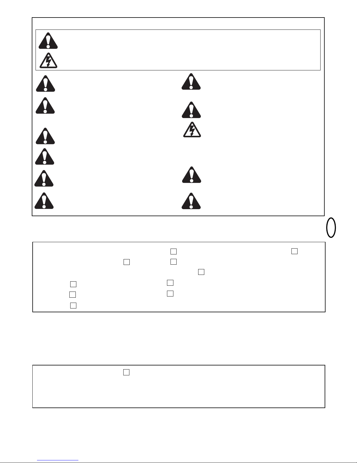
1-pt
Conteúdo: Instruções genéricas sobre
montagem e uso:
Índice: página 1
Conteúdo da caixa de embalagem: figura
Antes de começar: página 2
Lista de verificações: página 2
Tipos de portão/altura de montagem:
página 2, figura A-F
Situação do portão:
página 2, figura A-F
Encostos para o portão:
página 2, figura A-F
Massa de montagem e ângulo de abertura:
página 2-3, figura A-B
Ferragens do pilar/ferragens para o portão:
página 2-3, figura A-D
Destravamento dos braços de
accionamento: página 3, figura
Montagem dos braços de accionamento:
página 3, figura A-B
Cablagem:
página 3, figura
Trabalhos de manutenção: página 3
Colocação em funcionamento: página 3
Dados técnicos: página 3
Peças sobressalentes: figura
CONTEÚDO DA CAIXA DE EMBALAGEM
(1) Accionamento LYN & SCS (1/2)
(2) Ferragens do pilar LYN & SCS
(3) Chave por cada automatismo (2)
(4) Ferragens para o portão LYN & SCS (1)
(5) Condensador 230V (1)
(6) Manual de montagem (1)
(7) LYN Pernos (2) e anéis (4)
(8) SCS Pernos (2) e anéis (2)
(9) SCS Porcas (1) e anilha falsa (1)
1
COMECE POR LER ESTAS NORMAS DE SEGURANÇA IMPORTANTES
Estes símbolos de aviso significam "Cuidado!”, um pedido de atenção, uma vez que a sua inobservância poderá causar danos
pessoais e materiais. Leia estes avisos atentamente.
Este automatismo para portões foi construído e controlado de modo a oferecer condições de segurança adequadas, caso a
instalação e utilização sejam realizadas em conformidade com as normas de segurança que se indicam.
O não cumprimento das normas de segurança que se seguem pode dar origem a danos pessoais e materiais graves.
1
2
3
3
5
6
7
8
As linhas eléctricas devem ser colocadas em
conformidade com as normas de construção e de
instalação eléctrica locais. O cabo eléctrico só pode
ser conectado a uma rede devidamente ligada à terra
por um electrotécnico autorizado.
Aquando da montagem, há que ter em conta o movimento de
fecho entre a parte accionada e as partes adjacentes do
edifício (p. ex. uma parede) que se deve à abertura da parte
accionada.
Os aparelhos de comando automático têm que ser
separados da rede sempre que forem executados
trabalhos de manutenção, como por exemplo a limpeza.
A instalação de disposição fixa deverá integrar um
dispositivo de corte para garantir um desligamento para
todos os pólos mediante um interruptor (curso de
abertura do contacto de pelo menos 3mm) ou um fusível
separado.
Ao manusear ferramentas e peças pequenas, tenha
sempre o devido cuidado e não use anéis, relógios ou
peças de vestuário soltas quando realiza trabalhos de
instalação ou de reparação num portão.
Assegure-se de que as pessoas que montam o
accionamento e efectuam a sua manutenção e
operação cumprem estas instruções. Conserve as
instruções num local onde estejam sempre acessíveis para
consulta.
Remova todas as fechaduras fixadas no portão para
evitar danos no mesmo.
É importante manter o portão sempre em bom
funcionamento. Os portões encravados ou perros
devem ser imediatamente reparados. Não tente
reparar o portão você mesmo. Solicite a ajuda de um
técnico.
Remova acessórios adicionais da proximidade de crianças.
Não deixe as crianças operar botões e controlos remotos.
O portão poderá provocar ferimentos graves ao fechar.
Após a instalação deverá verificar se o mecanismo
está regulado correctamente e se o accionamento, o
sistema de segurança e o desbloqueio de emergência
funcionam em condições.
A protecção contra esmagamento e roçamento tem que
estar totalmente assegurada após a montagem do
accionamento com o portão.
Se o portão dispor de uma porta de passagem, o
accionamento não pode arrancar ou continuar a
funcionar caso o portão não esteja devidamente
fechado.
4
9
Page 34
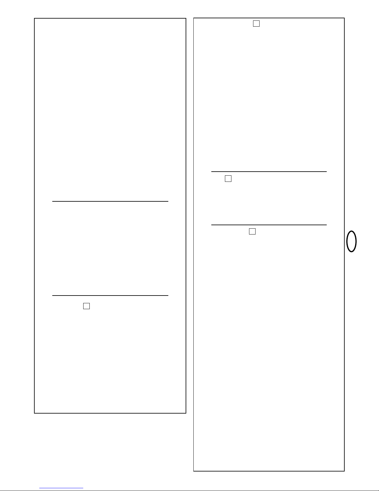
2-pt
SITUAÇÃO DO PORTÃO
Qual é o ângulo de abertura necessário do batente?
90 graus ou no máximo 115 graus. Um ângulo de abertura superior a
115 graus é possível sob determinadas condições mas não se
recomenda! Justificação: o accionamento funciona sempre à mesma
velocidade. Quanto maior for o ângulo de abertura do portão maior
terá que ser a velocidade do batente. Os movimentos tornam-se mais
irregulares, sujeitando as ferragens e o portão a um desgaste extremo.
Válido para automatismos sem interruptor de fim-de-curso: Em
caso de divergência dos ângulos de abertura, o accionamento, que
alcançar primeiro a sua meta, fica a "zumbir" no encosto (motor em
funcionamento) e a pressionar o portão até o outro motor atingir
igualmente a sua posição final (voir figura 3A-F).
Dica profissional: é possível controlar o tempo, que os batentes
precisam para alcançar o encosto final, utilizando as medidas A+B
com uma diferença conveniente (esquerda + direita). Com este tipo
de montagem, as ferragens são porém sujeitas a esforços elevados
e o deslocamento do portão poderá tornar-se irregular. Este método
só deve ser recomendado a construtores de portões experientes.
NOTA: Se o portão se abrir em direcção a um muro ou uma parede,
existe o risco de alguém ficar entalado. Se a distância que restar,
quando o portão se encontra aberto, for inferior a 200 mm,
posteriormente esta área terá de ser protegida mediante a
instalação de uma barreira fotoeléctrica ou uma régua de contactos.
ENCOSTOS
Um portão pivotante carece de encostos fixos para os
movimentos de abertura e fecho. Os encostos ajudam a
conservar o accionamento, o portão e as ferragens. A operação do
portão sem encostos finais fixos prejudica o funcionamento e é
frequentemente perigoso, causando um desgaste prematuro e
fazendo cessar a garantia!
FERRAGEM DO PILAR
A localização acertada da ferragem do pilar é determinante
para o funcionamento posterior da instalação. Ela define a
distância entre o ponto de rotação do motor e o ponto de rotação do
portão e, por conseguinte, o ângulo de abertura. Fala-se nas
medidas A e B. Não subestime a influência que estas medidas
exercem sobre o funcionamento e a mobilidade. Tente definir,
impreterivelmente e com a maior exactidão possível, a melhor
medida para o seu ângulo de abertura. Consulte a tabela (figura 3F)
relativamente às medidas A/B.
Se o pilar não for suficientemente largo, deve colocar uma placa
adaptadora (figura 5B). Se o pilar for demasiado espesso, terá que
desbastá-lo (figura 5D), ou deslocar o portão (figura 5C).
Para obter medidas optimizadas, poderá ser necessário reduzir ou
aumentar a placa de charneira fornecida. No caso de portões novos
pode influenciar-se as medidas A e B se as charneiras do portão
forem montadas de forma correspondente nos pilares. Antes de as
medidas de montagem serem determinadas definitivamente, é
necessário verificar sempre se o accionamento não pode encostar
no canto do pilar ao abrir ou fechar.
MONTAGEM: as forças com as quais o accionamento se apoia
contra o pilar são extremamente grandes. Na maior parte dos casos,
já é possível obter medidas de montagem aceitáveis se a placa de
charneira fornecida for soldada directamente ao pilar. No caso de
postes de pedra ou de betão grossos, é necessário soldar a peça de
charneira sobre uma placa de suporte e fixá-la de modo a que as
buchas não se possam soltar durante o funcionamento. Mais
adequadas do que buchas de expansão de aço ou material sintético
são as âncoras compostas de colagem, nas quais um pino roscado
é colado na parede sem tensão.
No caso de pilares revestidos de alvenaria deverá ser aparafusada
uma placa de aço maior que cubra várias pedras sobre a qual pode
depois ser soldada a placa de charneira. Uma placa angular fixada
em torno do bordo do pilar é também um óptimo meio de fixação.
DICA PARA ACESSÓRIO 1: No caso dos pilares redondos existe a
possibilidade de montar uma ferragem especial, com a finalidade de
facilitar o ajuste da medida A/B (modelo 207917).
DICA PARA ACESSÓRIO 2: No caso dos portões que abrem para
fora, existe a possibilidade de encomendar uma ferragem especial.
ANTES DE COMEÇAR
O accionamento precisa de espaço lateral para os braços e a
montagem. Certifique-se de que este se encontra disponível. Os
portões sujeitos a uma grande carga devido à pressão do vento
devem ser protegidos adicionalmente com um cadeado (eléctrico)!
Existem muitos factores que são determinantes para a escolha do
accionamento certo. O mais difícil num portão operacional é o
"arranque. Uma vez em movimento, o portão passa a necessitar de
bem menos força.
• Tamanho do portão: o tamanho do portão constitui um factor
muito importante. O vento pode travar ou prender o portão e fazer
com que seja necessária uma força substancialmente maior.
• Peso do portão: a indicação do peso do portão representa
apenas um valor característico aproximado que pode divergir
muitíssimo das necessidades efectivas. A função é importante.
• Influência da temperatura: as baixas temperaturas exteriores
podem dificultar ou impossibilitar o arranque (modificações do solo,
etc.). As elevadas temperaturas exteriores podem fazer actuar o
dispositivo de protecção térmica mais cedo (a aprox. 135°C) (só
nos automatismos de 230 V).
• Frequência de funcionamento/factor de duração de ciclo: os
accionamentos têm um factor máximo de duração de ciclo de
aprox. 30% (p. ex. 30% de uma hora). Os automatismos de 24 V
podem funcionar em permanência.
ATENÇÃO: 230 V os accionamentos não estão preparados para
funcionar prolongadamente com um o factor máximo de duração
de ciclo (funcionamento contínuo). O accionamento aquece
excessivamente e desliga até voltar a alcançar a temperatura de
ligação. A temperatura exterior e o portão representam grandezas
determinantes para o factor de duração de ciclo efectivo.
LISTA DE VERIFICAÇÕES / INSTALAÇÃO – PREPARATIVOS
Verifique o conteúdo da sua embalagem e leia o manual com
atenção. Certifique-se de que o portão funciona impecavelmente. O
portão deve deslocar-se de modo regular e sem quaisquer
impedimentos, não podendo ficar preso em nenhum ponto. Não se
esqueça de que a altura do solo pode aumentar alguns centímetros
durante o Inverno. A fim de evitar movimentos pendulares
indesejáveis, o portão deverá ser sólido e, tanto quanto possível,
isento de folga. Quanto melhor for a mobilidade do batente mais
precisa poderá ser a regulação da força.
Aponte os materiais, de que ainda necessita, e providencie-os antes
de iniciar a montagem. Parafusos de ancoragem de fixação por cola
(buchas sólidas), parafusos, encostos, cabos, caixas de distribuição,
ferramentas, etc.
TIPOS DE PORTÃO
O local de montagem do accionamento é determinado pelo tipo de
portão. Se o encosto do portão se encontrar no solo, o
accionamento também deverá ser montado o mais em baixo
possível, para que não possa empenar o portão. Utilize apenas
partes do aro para a fixação.
TIPO A, B, C
Nos portões de aço, a ferragem para portão deverá ser fixada ao aro
principal. Reforce o suporte disponível caso não tenha a certeza de
que é suficientemente robusto.
TIPO D, E, F
Nos portões de madeira, a ferragem para portão tem que ser
aparafusada. Recomendamos que instale uma placa do lado exterior
para que a fixação não se solte com o tempo. Os portões de
madeira finos devem ser reforçados adicionalmente, caso contrário
não resistem aos esforços a que estão sujeitos (p. ex. tipo F).
2
3
4
5
Page 35
3-pt
TRABALHOS DE MANUTENÇÃO
A parte mecânica do automatismo dispensa qualquer manutenção.
Verifique regularmente (todos os meses) se as ferragens do portão e
do automatismo estão firmemente montadas. Desbloqueie o
automatismo e teste o funcionamento do portão. Somente um portão
que se movimente sem quaisquer dificuldades é que estará apto a
funcionar com um automatismo. Um automatismo não remedeia,
portanto, um portão que funcione mal.
No caso dos automatismos de 24 V, consulte também o manual
do comando.
FERRAGEM PARA PORTÃO
A ferragem para portão deve ser montada horizontalmente à
ferragem do pilar. A distância entre as ferragens é designada por
medida de fixação. Com o portão fechado, o accionamento
encontra-se avançado 99%. Com o portão aberto, o accionamento
está avançado 1%. Se o êmbolo AVANÇAR ou RECOLHER
totalmente durante o funcionamento (com o portão), o accionamento
é danificado e a garantia cessa! A medida de fixação tem que ser
respeitada impreterivelmente! Medidas, ver figura 5A.
Nos portões de aço, os dispositivos de fixação deverão ser soldados
ou aparafusados. Em caso de aparafusamento, devem ser usadas
anilhas grandes ou uma placa na parte posterior. Nos portões de
madeira, o dispositivo de fixação tem que ser aparafusado. Será
extremamente conveniente colocar uma placa do lado exterior para
que a fixação não se possa soltar. Os portões de madeira finos sem
aro metálico têm que ser reforçados adicionalmente porque não
resistem a esforços contínuos (p. ex. o tipo F).
DESBLOQUEIO
O mecanismo de accionamento pode ser desbloqueado.
Seguidamente, o portão pode ser aberto e accionado à mão (em
caso de falha de corrente). Nos accionamentos novos, o desbloqueio
implica, por vezes, falta de mobilidade/deslocação irregular. Isto é
normal e não tem qualquer efeito sobre o funcionamento!
Desbloquear: introduza e rode a chave cilíndrica 180 graus. Gire
em seguida também a alavanca de desarme 180 graus. Pronto.
Bloquear: rode a alavanca para trás. Logo que o portão se mova ou
o accionamento comece a funcionar, a engrenagem volta a ficar
bloqueada. A alavanca pode agora ser presa com um cadeado para
que não possa ser desbloqueado sem autorização.
MONTAGEM DOS BRAÇOS DE ACCIONAMENTO
Desbloqueie o accionamento. Desloque o accionamento
desbloqueado sobre as ferragens e fixe-o com os pernos e anéis
fornecidos (figura 7).
Se orifício de fixação médio ou interior da ferragem do pilar for
utilizado, é necessário encurtar a ferragem do pilar antes da primeira
colocação em funcionamento, para garantir espaço suficiente para o
automatismo. A inobservância desta indicação leva à ruptura da
ferragem no automatismo! Não utilize um martelo nem um objecto
semelhante quando quiser colocar o automatismo na ferragem.
CABLAGEM
230 V: O cabo de ligação tem 4 pólos e um comprimento de cerca
de 80 cm, sendo conduzido, em arco, ao comando ou a uma caixa
de distribuição à prova de água e localizada acima do nível do solo.
A ligação a partir da caixa de distribuição é estabelecida através de
um cabo autorizado que é colocado de forma fixa. O condensador
pode ser conectado na caixa de distribuição ou no comando.
Ligação: O condensador é conectado entre os bornes OP e CL. OP
e COM determinam o sentido de rotação A. CL e COM têm como
consequência o sentido de rotação inverso. Nunca se esqueça de
ligar o sistema à terra (figura 7B).
24 V: O cabo de ligação tem 6 pólos e um comprimento de cerca de
80 cm, sendo conduzido, em arco, ao comando ou a uma caixa de
distribuição à prova de água e localizada acima do nível do solo. A
ligação a partir da caixa de distribuição é estabelecida através de um
cabo autorizado que é colocado de forma fixa.
Ligação: ver o manual do sistema de comando.
Cores dos cabos: castanho/verde/branco/amarelo=sensores
azul/vermelho: Motor de 24 V
DICA PARA ACESSÓRIO: Cabo de extensão LA400-JB40
Contém:
(1) Cabo de 12 m com bornes
(1) Caixa de distribuição IP65
(2) Cerra-cabos PG 13,5
(1) Material de montagem
PRIMEIRA COLOCAÇÃO EM FUNCIONAMENTO
Verifique à mão o funcionamento do portão com este destrancado. A
colocação em funcionamento da parte eléctrica só é possível com um
comando adequado, o qual pode ser adquirido à parte como acessório.
Certifique-se sempre de que as normas de segurança aplicáveis às
partes mecânica e eléctrica da instalação são estritamente cumpridas.
Se a força exercida pela folha do portão em movimento contra o
bordo do fecho for superior a 400 N, é necessário empregar
dispositivos de segurança adicionais (barreira fotoeléctrica, régua
de contactos). Os dispositivos de segurança terão de cumprir os
requisitos da norma EN60335-2-103.
5
6
7
7
DADOS TÉCNICOS
230 V
Ligação à rede (motor)
Tensão do motor
Consumo de corrente
Potência absorvida
Condensador
Largura máx. do portão
Peso máx. do portão
Classe de protecção
Cabo de ligação
Força axial
Velocidade de operação
Operação contínua
Gama de temperaturas
24 V
Ligação à rede (motor)
Tensão do motor
Consumo de corrente
Potência absorvida
Largura máx. do portão
Peso máx. do portão
Classe de protecção
Força (nominal)
Velocidade de operação
Tempo de abertura 90
O
s
Gama de temperaturas
220 – 240 V˜/ 50Hz
220-240 V
1,2A
280W
6,3μF
2,5m LYN300
4,0m LYN400
3,0m SCS300
250kg
I - IP 44
H07RN-F / 80cm
250N
20mm/s LYN300, SCS300
12mm/s LYN400
4 minutos
-20 ºC a +55 ºC
220 – 240 V/ 50Hz
24 V
2A
48W
2,5m LYN300
4,0m LYN400
3,0m SCS300
250kg
I - IP 44
250N
variável
aprox. 12 LYN300
aprox. 14 LYN400
aprox. 10 SCS300
-20 ºC a +55 ºC
Declaração de Conformidade
Os automatismos para portões de garagem das séries 14 LYN300, 14 LYN400 10
SCS300 enunciados estão em conformidade com as prescrições aplicáveis das normas
EN300220-3 • EN55014 • EN61000-3 • EN60555, EN60335-1 • ETS 300 683 • EN603351: 2002 • EN60335-2-103: 2003 • EN55014-1: 2000 + A1 + A2 • EN55014-2: 2001 •
EN61000-3-2: 2000 • EN61000-3-3: 1995 + A1 • EN 301 489-3, V1.3.1 • EN 300 220-3
V1.1.1 • EN 13241-1.
Estão igualmente em conformidade com as disposições das directivas europeias
...............................................................................2006/95/EC, 2004/108/EC, 1999/5/EG
Declaração de Incorporação
Os automatismos para portões só poderão ser declarados em conformidade com o
disposto na directiva "Máquinas", 89/392/CEE, e respectivas redacções posteriores, caso
tenham sido instalados e revistos de acordo com as instruções do fabricante, e desde
que sejam empregados com portões que tenham igualmente sido instalados e revistos de
acordo com as instruções do fabricante.
O declarante atesta, com a sua assinatura, a conformidade do aparelho mencionado
supra e de todos os demais acessórios enunciados no manual, com as normas e
prescrições regulamentares supracitadas.
B.P.Kelkhoff
Manager, Regulatory Affairs
Chamberlain GmbH
D-66793 Saarwellingen
January, 2008
Page 36
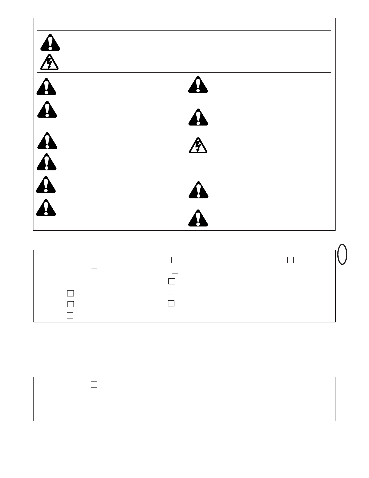
1-pl
TreÊç: Informacje ogólne dot. monta˝u i
u˝ytkowania:
Spis treÊci: strona 1
ZawartoÊç kartonu: rys.
Informacje wst´pne: strona 2
Lista kontrolna: strona 2
Typy bramy / wysokoÊç monta˝u:
strona 2, rys. A-F
Konfiguracja bramy:
strona 2, rys. A-F
Ograniczniki bramy:
strona 2, rys. A-F
Wymiary monta˝owe i kàt otwarcia::
strona 2-3, rys. A-B
Okucie s∏upa / okucie bramy:
strona 2-3, rys. A-D
Zwalnianie ramion nap´du:
strona 3, rys.
Monta˝ ramion nap´dowych:
strona 3, rys. A-B
Okablowanie:
strona 3, rys.
Prace konserwacyjne: strona 3
Uruchomienie: strona 3
Dane techniczne: strona 3
Cz´Êci zamienne: rys.
ZAWARTOå KARTONU
(1) Nap´d LYN & SCS (1/2)
(2) Okucie s∏upa LYN & SCS
(3) Klucze na ka˝dy nap´d (2)
(4) Okucie bramy LYN & SCS (1)
(5) Kondensator 230V (1)
(6) Instrukcja monta˝u (1)
(7) LYN Trzpienie (2) i pierÊcienie (4)
(8) SCS Trzpienie (2) i pierÊcienie (2)
(9) SCS Nakr´tka (1) i podk∏adka (1)
1
PROSZ¢ ROZPOCZÑå OD PRZECZYTANIA TYCH WA˚NYCH ZASAD DOTYCZÑCYCH BEZPIECZE¡TWA
Te symbole oznaczajà "Ostrze˝enie” i wezwanie do ich przestrzegania, poniewa˝ w przeciwnym razie spowodowane mogà
byç zranienia personelu albo szkody rzeczowe. Prosi si´ o uwa˝ne zapoznanie z tymi ostrze˝eniami.
Nap´d bramy zosta∏ skonstruowany i sprawdzony tak, ˝e w przypadku instalacji i u˝ytkowania z przestrzeganiem
podawanych dalej zasad bezpieczeƒstwa, zapewnia on odpowiednie bezpieczeƒstwo.
Nie przestrzeganie podawanych ni˝ej zasad bezpieczeƒstwa mo˝e powodowaç powa˝ne zranienia personelu lub szkody
rzeczowe.
3.0
1
2
3
3
5
6
7
8
Przewody elektryczne nale˝y uk∏adaç zgodnie z
miejscowymi przepisami dotyczàcymi budownictwa oraz
instalacji elektrycznych. Kable elektryczne mogà byç
pod∏àczane wy∏àcznie do w∏aÊciwie uziemionej sieci
przez upowa˝nionego do tego specjalist´ z dziedziny
elektrotechniki.
Przy monta˝u uwzgl´dniona musi byç mo˝liwoÊç zamkni´cia
pomi´dzy cz´Êcià nap´dzanà a cz´Êcià sàsiadujàcego
budynku (np. Êcianà), gdy ma miejsce ruch zwiàzany z
otwieraniem.
Gdy wykonywane sà prace konserwacyjne w rodzaju
na przyk∏ad czyszczenia, sterowane automatycznie
urzàdzenia muszà byç od∏àczone od sieci. W trwa∏ej
instalacji nale˝y przewidzieç urzàdzenie do od∏àczania ,
aby zapewniaç od∏àczanie wszystkich faz przy u˝yciu
wy∏àcznika (droga dla otwarcia styków wynoszàca co
najmniej 3mm) albo oddzielne bezpieczniki.
W przypadku stosowania narz´dzi oraz ma∏ych cz´Êci, w
zwiàzku z monta˝em lub wykonywaniem prac
naprawczych przy bramie, prosz´ zachowaç ostro˝noÊç i
nie nosiç pierÊcionków, zegarków czy luênej odzie˝y.
Prosz´ si´ upewniç, czy osoby, które montujà,
konserwujà czy te˝ obs∏ugujà nap´d bramy, post´pujà
zgodnie z tymi instrukcjami. Prosz´ trzymaç te instrukcje
w takim miejscu, aby mo˝liwe by∏o szybkie si´gni´cie do
nich, w razie potrzeby.
Prosz´ usunàç ewentualne zamocowane na bramie
zamki aby uniknàç jej uszkodzenia.
Wa˝ne jest zapewnienie, aby brama zawsze by∏a
zachowana w stanie umo˝liwiajàcym jej dobre
przemieszczanie. Bramy, które si´ zacinajà lub
zakleszczajà, nale˝y natychmiast naprawiç. Bramy nie
nale˝y próbowaç naprawiaç samodzielnie. Prosz´ do tego
zaanga˝owaç specjalist´.
Dodatkowe wyposa˝enie przechowywaç z dala od
dzieci. Nie pozwalaç, aby dzieci obs∏ugiwa∏y przyciski
czy te˝ przyrzàdy do zdalnego sterowania. Brama
mo˝e spowodowaç powa˝ne zranienia w przypadku jej
zamykania.
Po zainstalowaniu, konieczne jest sprawdzenie, czy
mechanizm jest prawid∏owo ustawiony i czy nap´d,
system zabezpieczajàcy i awaryjne odblokowanie
dzia∏ajà prawid∏owo.
Ostateczna ochrona przed zgnieceniem lub
skaleczeniem musi byç zapewniona po zamontowaniu w
bramie nap´du.
Nap´d ten nie mo˝e byç uruchamiany, czy te˝ dalej
dzia∏aç, gdy w bramie istnieje furtka i nie jest
prawid∏owo zamkni´ta.
4
9
Page 37

2-pl
KONFIGURACJA BRAMY
Na ile musi byç otwierane skrzyd∏o bramy?
90 stopni albo do 115 stopni. Kàt otwarcia przekraczajàcy
115 stopni jest warunkowo mo˝liwy ale nie jest zalecany !
Przyczyna : nap´d zawsze dzia∏a z tà samà pr´dkoÊcià. Im dalej
brama musi byç otwierana, tym szybciej musi si´ przemieszczaç
skrzyd∏o bramy. Ruchy stajà si´ nieregularny i okucia oraz brama
poddawane sà ekstremalnym napr´˝eniom.
Dotyczy nap´dów bez wy∏àcznika kraƒcowego: Nie identyczne
kàty otwarcia powodujà, ˝e nap´d, który najpierw osiàgnà∏ swe
po∏o˝enie docelowe na ograniczniku "buczy” (w zwiàzku z
dzia∏ajàcym silnikiem) i dociska bram´, a˝ inny silnik równie˝
osiàgnie swe po∏o˝enie kraƒcowe (rys. 3A-F).
Wskazówka dla profesjonalistów: Czas wymagany dla
osiàgni´cia ogranicznika kraƒcowego, mo˝e byç kontrolowany
przez zamierzony wybór ró˝nych wymiarów A i B (lewy + prawy).
Ta metoda monta˝u powoduje jednak poddawanie okuç du˝ym
napr´˝eniom i mo˝e powodowaç, ˝e brama b´dzie si´
przemieszczaç nieregularnie. Zaleca si´, aby metod´ tà stosowali
tylko doÊwiadczeni monterzy bram.
UWAGA: je˝eli brama otwiera si´ w stron´ muru lub Êciany istnieje
niebezpieczeƒstwo zakleszczenia. Je˝eli przy otwartej bramie
pozosta∏y odst´p jest mniejszy ni˝ 200 mm, obszar ten musi
zostaç póêniej zabezpieczony dodatkowo przy pomocy zapory
Êwietlnej lub listwy stykowej.
OGRANICZNIKI
Brama obrotowa wymaga ogranicznika w kierunku jej
OTWARCIA i ZAMKNI¢CIA. Ograniczniki oszcz´dzajà przed
zu˝yciem nap´d, bram´ i okucia. Eksploatacja bramy bez
zamocowanych w sposób trwa∏y ograniczników prowadzi do jej
kiepskiego dzia∏ania. Jest ona cz´sto niebezpieczna, prowadzi to
do przedwczesnego zu˝ycia i powoduje utrat´ wa˝noÊci gwarancji!
OKUCIE S¸UPA
Wybór prawid∏owego po∏o˝enia okucia s∏upa ma decydujàce
znaczenie dla póêniejszego dzia∏ania urzàdzenia. OkreÊla to
odleg∏oÊç pomi´dzy punktem obrotu silnika a punktem obrotu bramy
a co za tym idzie kàt otwarcia. Wymiary te przytaczane sà, jako
wymiar A i wymiar B. Nie nale˝y lekcewa˝yç wp∏ywu tych wymiarów
na dzia∏anie i ruch. Na tyle na ile to mo˝liwe i odpowiednie dla
wszystkich okolicznoÊci, nale˝y wypróbowaç i osiàgnàç najlepszy
wymiar dla interesujàcego Was kàta otwarcia. Odsy∏a si´ do tablicy
(rys. 3F), gdzie mo˝na znaleêç wymiary A/B.
Gdy s∏up nie jest wystarczajàco szeroki, konieczne jest przygotowanie
p∏yty adaptera (rys. 5B). Gdy s∏up jest zbyt gruby (rys. 5D), musi byç
wyj´ty albo brama musi byç przesuni´ta (rys. 5C).
Aby osiàgnàç optymalne wymiary, konieczne mo˝e byç skracanie
albo wyd∏u˝anie dostarczanej p∏yty zawiasowej. W przypadku bram
wykonywanych od nowa, gdy zawiasy bramowe sà odpowiednio
mocowane na s∏upach, mo˝liwy jest wp∏yw na wymiary A i B. Zanim
okreÊlone b´dà ostateczne wymiary monta˝owe, powinno si´
zawsze sprawdziç, czy nie istnieje ewentualna mo˝liwoÊç
uderzenia nap´du w s∏up, gdy brama si´ obraca.
MONTA˚: Nap´d wywiera bardzo du˝e si∏y na s∏up. Mo˝liwe do
przyj´cia wymiary monta˝owe sà zwykle uzyskiwane, gdy
dostarczana p∏yta zawiasowa jest spawana bezpoÊrednio na s∏upie.
W przypadku grubych s∏upów kamiennych albo betonowych,
zawias musi byç spawany do p∏yty wsporczej i mocowany tak, aby
ko∏ki ustalajàce nie mog∏y si´ luzowaç podczas dzia∏ania. ¸àczone
klejem kotwy, w przypadku których gwintowany ko∏ek wklejany jest
w mur w sposób pozbawiony napr´˝eƒ, sà bardziej odpowiednie
ni˝ stalowe czy wykonane ze sztucznego tworzywa dyble
rozpr´˝ne. W przypadku s∏upów murowanych, nale˝y przykr´ciç
stosunkowo du˝à stalowà p∏yt´, która przykryje kilka cegie∏ i
nast´pnie do niej mo˝na spawaç p∏yt´ zawiasowà. P∏yta kàtowa
wspó∏dzia∏ajàca z naro˝em s∏upa jest równie˝ odpowiednim
Êrodkiem do mocowania.
AKCESORIA WSKAZÓWKA 1: do okràg∏ych s∏upów mo˝na
zamontowaç okucie akcesoryjne, które u∏atwia nastawienie
wymiaru A/B (model 207917).
AKCESORIA WSKAZÓWKA 2: do bram wychylajàcych si´ na
zewnàtrz mo˝na zamówiç specjalne okucie.
INFORMACJE POCZÑTKOWE
Mechanizm nap´dowy wymaga po bokach miejsca na ramiona i
monta˝. Prosz´ si´ upewniç, czy miejsce to jest do dyspozycji.
Bramy, na które dzia∏ajà du˝e obcià˝enia wiatru nale˝y równie˝
zabezpieczyç przy u˝yciu dodatkowego zamka (elektrycznego).
O dokonaniu w∏aÊciwego wyboru mechanizmu nap´dowego
decyduje wiele czynników. Zak∏adajàc, ˝e brama dzia∏a w∏aÊciwie,
"uruchamianie” jest najtrudniejszà fazà. Gdy brama jest ju˝ w
ruchu, to do przemieszczania wymaga ona ju˝ zwykle znacznie
mniejszej si∏y.
• WielkoÊç bramy: WielkoÊç bramy jest bardzo wa˝nym
czynnikiem. Wiatr mo˝e powodowaç hamowanie bramy albo
okreÊlone napr´˝enia, zwi´kszajàc w znaczàcy sposób wielkoÊç
si∏y wymaganej do jej przemieszczania.
• Ci´˝ar bramy: Ci´˝ar bramy stanowi tylko przybli˝ony parametr,
który mo˝e znacznie odbiegaç od rzeczywistych potrzeb. Wa˝ne
jest dzia∏anie.
• Wp∏yw temperatury: Niskie temperatury zewn´trzne mogà
utrudniaç lub uniemo˝liwiaç uruchomienie (zmiany w gruncie
etc.). Wysokie temperatury zewn´trzne mogà przedwczeÊnie
wyzwalaç zabezpieczenie termiczne (oko∏o 135°C). (Tylko przy
nap´dach 230 V).
• Cz´stotliwoÊç obs∏ugi / czas w∏àczenia: Nap´dy posiadajà
maksymalny czas w∏àczania oko∏o 30% (np. 30% w przeciàgu
godziny). Nap´dy 24 V mogà pracowaç ciàgle.
UWAGA: nap´dy 230 V nie zosta∏y zaprojektowane do ciàg∏ego
dzia∏ania z zachowaniem swego maksymalnego czasu w∏àczenia
(pracy ciàg∏ej). Nap´d staje si´ zbyt goràcy i wy∏àcza si´, dopóki
nie osiàgnie znowu temperatury za∏àczania. Temperatura
zewn´trzna oraz brama sà wa˝nymi parametrami, które majà
wp∏yw na rzeczywisty czas w∏àczenia.
LISTA KONTROLNA INSTALACJI – PRZYGOTOWANIA
Sprawdziç zawartoÊç opakowania i uwa˝nie przeczytaç instrukcje.
Upewniç si´, ˝e wyposa˝enie bramy dzia∏a w sposób niezawodny.
Brama musi dzia∏aç w sposób równomierny i bez-udarowy i nie
mo˝e utykaç w jakimkolwiek punkcie. Nale˝y pami´taç, ˝e poziom
gruntu mo˝e si´ w zimie podnieÊç o kilka centymetrów. Brama
powinna byç stabilna i na tyle na ile to mo˝liwe wolna od luzów aby
uniemo˝liwiç niepo˝àdane i wahad∏owe ruchy. Im ∏atwiej porusza
si´ skrzyd∏o bramy, tym czulsza musi byç regulacja si∏y.
Nale˝y zapisaç, jakie materia∏y sà Wam jeszcze potrzebne i
zapewniç je przed rozpocz´ciem monta˝u. Dotyczy to klejonych
kotw (stabilizujàcych dybli), Êrub, ograniczników, kabli, skrzynek
rozdzielczych, narz´dzi etc.
TYPY BRAMY
Typ bramy decyduje o po∏o˝eniu, w którym zamontowany jest
nap´d. Gdy ogranicznik bramy znajduje si´ na gruncie, nap´d
powinien byç równie˝ zamontowany mo˝liwie nisko tak, aby nie
by∏o mo˝liwe skr´cenie bramy. W celu mocowania, stosowaç tylko
cz´Êci ramy.
TYP A, B, C
W przypadku bram stalowych, okucie bramy powinno byç
zamocowane do ramy g∏ównej. W przypadku wàtpliwoÊci odnoÊnie
wystarczajàcej stabilnoÊci b´dàcego do dyspozycji wspornika,
nale˝y go wzmocniç.
TYP D, E, F
W przypadku bram drewnianych, okucie bramy musi byç skr´cane
na wylot. Doradza si´ zastosowanie p∏yty z zewnàtrz tak, aby
mocowanie nie mog∏o si´ poluzowaç z biegiem czasu. Cienkie
drewniane bramy muszà byç dodatkowo wzmocnione, aby
wytrzymaç wyst´pujàce napr´˝enia (np. typ F).
2
3
4
5
Page 38
3-pl
KONSERWACJA
Mechanika nap´du nie wymaga konserwacji. W regularnych
odst´pach czasu (co miesiàc) nale˝y sprawdzaç, czy okucia
bramowe oraz nap´d sà zamocowane w bezpieczny sposób.
Odryglowaç nap´d i sprawdziç, czy brama dzia∏a w∏aÊciwie. Tylko
lekko poruszajàca si´ brama b´dzie dobrze dzia∏aç z nap´dem.
Nap´d nie mo˝e wyeliminowaç problemów powodowanych przez
êle dzia∏ajàcà bram´.
W przypadku nap´dów 24 V zobacz tak˝e instrukcj´
sterownika.
OKUCIE BRAMY
Okucie bramy musi byç montowane w poziomie w stosunku do okucia
s∏upa. Odleg∏oÊç mi´dzy okuciami okreÊlana jest wymiarem
zamocowania. Gdy brama jest zamkni´ta nap´d wykona∏ ruch
wysuwu do 99%. W stanie otwartym bramy po∏o˝enie nap´du
odpowiada 1%. Ca∏kowite WSUWANIE albo WYSUWANIE t∏oka
podczas dzia∏ania (bramy) powoduje uszkodzenie nap´du i prowadzi
do wygaÊni´cia gwarancji!. We wszystkich okolicznoÊciach prosz´
zachowywaç wymiar zamocowania! Wymiary zobacz rysunek 5A.
W przypadku bram stalowych, ∏àczniki powinny byç spawane lub
przykr´cane skroÊnie. W przypadku skroÊnego skr´cania, stosowaç
nale˝y du˝e podk∏adki albo p∏yt´ po drugiej stronie. W przypadku
bram drewnianych przy mocowaniu stosowaç wiercenie skroÊne.
Mocowanie p∏yty z zewnàtrz jest stanowczo zalecane tak, aby nie
mog∏o ono byç poluzowane. Cienkie drewniane bramy bez
metalowej ramy muszà byç dodatkowo wzmocnione, aby
wytrzymaç ciàg∏e napr´˝enia (np. typu F).
DLUZOWANIE
Mechanizm nap´dowy mo˝e byç luzowany. Brama mo˝e byç
nast´pnie otwierana i obs∏ugiwana r´cznie (zanik zasilania). W
przypadku nowych nap´dów, dzia∏anie luzujàce mo˝e byç czasami
postrzegane jako szarpane lub usztywnione. Jest to objaw
normalny i nie ma wp∏ywu na dzia∏anie.
Luzowanie: W∏o˝yç cylindryczny klucz i obróciç go o 180 stopni.
Nast´pnie obróciç dêwigni´ zwalniania równie˝ o 180 stopni.
Nast´puje luzowanie!
Blokowanie: Obracaç dêwigni´ do ty∏u. Gdy tylko brama si´
porusza albo nap´d dzia∏a, przek∏adnia jest znowu blokowana. Przy
u˝yciu zamka dêwignia mo˝e byç teraz zabezpieczona przed
nieupowa˝nionym zwolnieniem.
MONTA˚ RAMION NAP¢DU
Odblokowaç nap´d. Przesunàç odblokowany nap´d do okucia i
zabezpieczyç go przy u˝yciu dostarczonych sworzni i pierÊcieni
(rys. 7).
Je˝eli na okuciu s∏upa do zamocowania zostanie wykorzystany
otwór Êrodkowy lub wewn´trzny, przed pierwszym uruchomieniem
musi zostaç skrócona p∏yta zawiasowa s∏upa tak, aby pozostawiç
wystarczajàcà przestrzeƒ dla nap´du. Niespe∏nienie tego wymogu
doprowadzi do p´kni´cia zamocowania nap´du! Przy zak∏adaniu
nap´du na zawias nie wolno pos∏ugiwaç si´ m∏otkiem lub temu
podobnym narz´dziem.
OKABLOWANIE
230 V: 4-˝y∏owy kabel ∏àczàcy ma d∏ugoÊç wynoszàcà w przybli˝eniu
80 cm i jest uk∏adany w krzywiênie ∏ukowej do sterownika albo
wodoszczelnej skrzynki rozdzielczej zlokalizowanych nad ziemià.
Zaaprobowany kabel jest zainstalowany w sposób trwa∏y od skrzynki
rozdzielczej. Kondensator mo˝e byç pod∏àczany wewnàtrz skrzynki
rozdzielczej albo w sterowniku.
Po∏àczenie: kondensator zaciskany jest mi´dzy zaciskami OP i CL.
OP i COM zapewniajà kierunek obrotów A. CL i COM zapewniajà
odwrotny kierunek obrotów. Nigdy nie zapominaç o uziemieniu
instalacji (rys. 7B).
24 V: kabel przy∏àczeniowy jest 6-˝y∏owy, ma d∏ugoÊç ok. 80 cm i
jest uk∏adany ∏ukiem do sterownika lub wodoszczelnej skrzynki
rozdzielczej zlokalizowanej nad ziemià. Zaaprobowany kabel jest
zainstalowany w sposób trwa∏y od skrzynki rozdzielczej.
Po∏àczenie: zobacz instrukcj´ sterownika.
Po∏àczenie: zobacz instrukcj´ sterownika
Kolory kabla: Bràzowy/Zielony/Bia∏y/˚ó∏ty=czujniki
Niebieski/Czerwony: silnik 24 V.
AKCESORIA WSKAZÓWKA: kabel przed∏u˝ajàcy LA400-JB40
Zawiera:
(1) 12 m kabla z zaciskami
(1) skrzynk´ rozdzielczà IP65
(2) odcià˝niki PG 13,5
(1) materia∏ monta˝owy
PIERWSZE URUCHOMIENIE
Po zluzowaniu bramy, sprawdziç r´cznie jej dzia∏anie. Uruchomienie
elektryczne mo˝e byç zrealizowane tylko z odpowiednim
sterownikiem, który mo˝na nabyç jako element wyposa˝enia.
Zawsze nale˝y zwracaç uwag´ na to, aby przestrzegane by∏y
przepisy dotyczàce bezpieczeƒstwa elektrycznego i mechanicznego,
które znajdujà zastosowanie w odniesieniu do danej instalacji. Je˝eli
si∏a na kraw´dzi zamykajàcej poruszajàcego si´ skrzyd∏a jest
wi´ksza ni˝ 400 N, konieczne jest zainstalowanie dodatkowych
urzàdzeƒ zabezpieczajàcych (fotokomórka, listwa stykowa).
Urzàdzenia zabezpieczajàce muszà spe∏niaç wymogi okreÊlone
przez norm´ EN60335-2-103.
5
6
7
7
DANE TECHNICZNE
230 V
Zasilanie sieciowe (silnik)
Napi´cie silnika
Pobór pràdu
Pobór mocy
Kondensator
Maks. szerokoÊç bramy
Maks. ci´˝ar bramy
Klasa ochrony
Kabel ∏àczàcy
Si∏a dzia∏ajàca w osi
Pr´dkoÊç przemieszczania
Dzia∏anie ciàg∏e
Zakres temperatury
24 V
Zasilanie sieciowe (silnik)
Napi´cie silnika
Pobór pràdu
Pobór mocy
Maks. szerokoÊç bramy
Maks. ci´˝ar bramy
Klasa ochrony
Si∏a (nominalna)
Pr´dkoÊç przemieszczania
Czas otwarcia 90° sek.
Zakres temperatury
220 – 240 V / 50Hz
220-240 V
1,2A
280W
6,3µF
2,5m LYN300
4,0m LYN400
3,0m SCS300
250kg
I - IP 44
H07RN-F / 80cm
250N
20mm/s LYN300, SCS300
12mm/s LYN400
4 minuty
-20°C do + 55°C
220 – 240 V / 50Hz
24 V
2A
48W
2,5m LYN300
4,0m LYN400
3,0m SCS300
250kg
I - IP 44
250N
zmienna
ok. 12 LYN300
ok. 14 LYN400
ok. 10 SCS300
-20°C do + 55°C
Deklaracja zgodnoÊci
Automatyczne nap´dy bram modeli serii LYN300, LYN400, SCS300 spe∏niajà wymogi
obowiàzujàcych ust´pów przepisów norm EN300220-3 • EN55014 • EN61000-3 •
EN60555, EN60335-1 • ETS 300 683 • EN60335-1: 2002 • EN60335-2-103: 2003 •
EN55014-1: 2000 + A1 + A2 • EN55014-2: 2001 • EN61000-3-2: 2000 • EN61000-3-3:
1995 + A1 • EN 301 489-3, V1.3.1 • EN 300 220-3 V1.1.1 • EN 13241-1
soraz postanowienia i wszystkie nowelizacje dyrektyw UE
...........................................................................2006/95/EC, 2004/108/EC, 1999/5/WE
Deklaracja inkorporacji
Automatyczne nap´dy bram spe∏niajà postanowienia dyrektywy UE 89/393/EEC i jej
nowelizacji, je˝eli sà zainstalowane i konserwowane zgodnie z instrukcjami producenta
oraz je˝eli u˝ytkowane sà z bramà, która tak˝e zosta∏a zainstalowana i jest
konserwowana zgodnie z instrukcjami producenta.
Ni˝ej podpisana oÊwiadcza niniejszym, ˝e okreÊlone powy˝ej urzàdzenia oraz ca∏e
wyposa˝enie dodatkowe wymienione w podr´czniku sà zgodne z podanymi wy˝ej
dyrektywami i normami.
B. P. Kelkhoff
Manager, Regulatory Affairs
Chamberlain GmbH
D-66793 Saarwellingen
January, 2008
Page 39

1-ru
Содержание: Общие указания по монтажу
и эксплуатации:
Оглавление: стр. 1
Содержимое ящика: рисунок
Прежде, чем начать: стр. 2
Контрольный список: стр. 2
Типы ворот / высота монтажа::
стр. 2, рисунок A-F
Расположение ворот:
стр. 2, рисунок A-F
Ограничители для ворот:
стр. 2, рисунок A-F
Монтажная масса и угол раскрытия:
стр. 2-3, рисунок A-B
Накладка стояка / налкадка ворот:
стр. 2-3, рисунок A-D
Деблокирование консоли привода:
стр. 3, рисунок
Монтаж консоли привода:
стр. 3, рисунок A-B
Прокладка кабелей:
стр. 3, рисунок
Техобслуживание: стр. 3
Первое включение: стр. 3
Технические характеристики: стр. 3
Запчасти: рисунок
Содержимое ящика
(1) Привод LYN & SCS (1/2)
(2) Накладка стояка LYN & SCS
(3) Ключ Настоящим (2)
(4) Накладка ворот LYN & SCS (1)
(5) Конденсатор 230V (1)
(6) Инструкция по монтажу (1)
(7) LYN Болты (2) и кольца (4)
(8) SCS Болты (2) и кольца (2)
(9) SCS Гайка (1) и Шайба (1)
1
ПЕРЕД НАЧАЛОМ РАБОТ ПРОЧИТАЙТЕ ЭТИ ВАЖНЫЕ ПРАВИЛА ТЕХНИКИ БЕЗОПАСНОСТИ
Эти предупреждающие символы означают “Внимание”, обращение к Вашему вниманию, так как их несоблюдение
могло бы причинить вред здоровью человека или материальный ущерб.
Пожалуйста, внимательно прочитайте эти предупреждения.
Данный привод ворот сконструирован и оттестирован таким образом, чтобы при своей установке и
использовании (при точном соблюдении правил техники безопасности) он предоставлял бы пользователю
относительную безопасность.
Итогом несоблюдения настоящих правил техники безопасности может быть вред, причиненный здоровью людей
или материальный ущерб.
3.0
1
2
3
3
5
6
7
8
Электропроводку необходимо прокладывать в
соответствии с местными строительными нормами
и инструкциями, относящимися к электропроводке.
Подключение электрического кабеля к правильно
заземленной сети может осуществлять лишь
авторизованный работник - электрик.
При монтаже необходимо принять во внимание
опасность зажатия между перемещаемой частью
ворот и окружающими частями здания,например:
стеной.
При осуществлении работ по уходу, например: при
очистке, автоматически управляемые устройства
должны быть отключены из сети электропитания.
У жестко подключенной электропроводки
необходимо помнить об устройстве размыкания для
того, чтобы во всех полях отключения было бы
гарантировано отключение при помощи
переключателя (размыкание контактов не менее
3 мм) или при помощи отдельного предохранителя.
При манипуляциях с инструментами и мелкими
частями действуйте с осторожностью и не носите
кольца (перстни), часы и свободную одежду (если на
воротах осуществляются работы по их установке и
ремонту).
Обеспечьте, чтобы те лица, которые осуществляют
монтаж, уход и обслуживание привода, соблюдали
требования настоящей инструкции. Инструкцию
разместите в таком месте, где бы она была быстро
доступна.
Для того, чтобы воспрепятствовать возникновению
повреждений, пожалуйста, удалите из ворот все
вмонтированные в них замки.
Важно, чтобы перемещение ворот было бы постоянно
гладким. Ворота, которые заклинятся или будут
заедать, необходимо немедленно отремонтировать.
Не пробуйте ремонтировать ворота сами. Обратитесь
за помощью к специалисту.
Дополнительные устройства разместите так, чтобы они
не были доступны детям. Не позволяйте детям, чтобы
они манипулировали с кнопками и дистанционным
управлением. Закрывающиеся ворота могут причинить
тяжелые ранения.
После установки необходимо проверить механизм
на правильность его настройки, а также привод,
системы безопасности и аварийного
отблокирования на предмет их правильного
функционирования.
После монтажа привода должна быть безусловно
обеспечена охрана мест, в которых существует угроза
возникновения ушибов и порезов.
Если в воротах установлены двери для прохода, то
приводной механизм нельзя запустить или оставить
его включенным до тех пор, пока ворота не будут
должным образом закрыты.
4
9
Page 40
2-ru
РАЗМЕЩЕНИЕ ВОРОТ
Как далеко должно открываться крыло?
До 90 градусов или до 115 градусов. Угол открытия более 115
градусов возможен, однако не рекомендован! Причина: Привод
всегда работает с постоянной скоростью. Чем больше должны
открываться ворота, тем быстрее должно перемещаться крыло.
Поэтому перемещения становятся неравномерными, фурнитура
и ворота испытывают экстремальные нагрузки.
Для приводов без конечных выключателей: Различный угол
открытия ведет к тому, что привод, который раньше достигнет
своей цели, гудит на ограничителе (работающий двигатель) и
давит на ворота до тех пор, пока другой двигатель тоже не
достигнет своего конечного положения (рисунок 3A-F).
Профессиональный совет: Благодаря специально сделанным
различным размерам А + В (влево + вправо) время достижения
конечного огграничителя можно контролировать. Однако, при
этом способе монтажа, фурнитура испытывает высокие
нагрузки и это может привести к постоянному движению ворот.
Использование этого метода рекомендуется только для
опытного строителя ворот.
УКАЗАНИЕ: Если ворота открываются к каменной стене или
перегородке, то существует опасность защемления людей. При
зазоре менее 200 мм для обеспечения безопасности эта
область должна быть дополнительно оборудована фотоячейкой
или контактной планкой.
ОГРАНИЧИТЕЛИ ХОДА
Для вращающихся ворот требуется прочный ограничитель
для открытия и закрытия ворот. Ограничители защищают
привод, ворота и фурнитуру. Работа ворот без прочных
конечных ограничителей ведет к ухудшению хода ворот, этот
ход часто небезопасен, означает досрочный износ и ведет к
прекращению гарантии!
ФУРНИТУРА СТОЙКИ
Правильное размещение фурнитуры стойки имеет
решающее значение для последующей работы
оборудования. Фурнитура определяет расстояние от середины
поворота двигателя к середине поворота ворот, а тем самым, и
угол поворота. Речь идет о размере А и размере В. Не
недооценивайте влияние этих размеров на функции и ход ворот.
Попробуйте достигнуть наилучшего размера для Вашего угла
открытия при всех обстоятельствах и как можно точнее. См.
таблицу для размеров А/В (рисунок 3F).
Если стойка недостаточно широка, то можно изготовить щитовой
адаптер (рисунок 5В). Если стойка слишком толстая Если стойка
недостаточно широка, то можно изготовить щитовой адаптер
(рисунок 5D). Если стойка слишком толстая, то ее необходимо
сделать тоньше или пересадить ворота., то ее необходимо
сделать тоньше или пересадить ворота (рисунок 5C).
Возможно, что для достижения оптимальных размеров будет
необходимо сократить или нарастить пластины шарнирной
петли, которая входит в комплект поставки. У вновь
изготовляемых ворот можно, если на стойке правильно
смонтировать пальцы ворот, изменить воздействие на размеры
А и В. Перед конечным определением монтажных размеров
необходимо всегда проверить, не сможет ли привод при его
отклонении натолкнуться на стойку.
МОНТАЖ: Силы, которыми привод опирается на стойку, весьма
высоки. Чаще всего можно достигнуть подходящих монтажных
размеров тогда, когда пластина шарнирной петли приваривается
непосредственно на стойку. У толстых каменных и бетонных стоек
петли необходимо приварить на пластину балки и прикрепить ее
так, чтобы дюбели при эксплуатации не могли бы ослабнуть.
Лучше всего (по сравнению со стальными или пластиковыми
разжимными дюбелями) для этих целей годятся приклеиваемые
сочлененные якоря, у которых в кладку вклеивается винтовой
шуруп со шлицем. К каменным стойкам должна привинчиваться
большая стальная пластина, перекрывающая несколько кирпичей,
на которую потом можно приварить пластину шарнирной петли.
Для закрепления также хорошо подходит угловая пластина,
прикрепленная вокруг грани стойки.
1-Й СОВЕТ ПО ПРИНАДЛЕЖНОСТЯМ: Для круглых стоек может
быть смонтирована накладка из состава принадлежностей,
которая позволяет упростить регулировку габарита А/В (Модель
207917).
2-Й СОВЕТ ПО ПРИНАДЛЕЖНОСТЯМ: Для ворот,
открывающихся наружу, может быть заказана специальная
накладка.
ПРЕЖДЕ, ЧЕМ НАЧНЕТЕ РАБОТАТЬ
Для установки привода и подсоединения к нему плечей
требуется свободное место. Пожалуйста, организуйте
необходимое свбодное место. Ворота, испытывающие сильную
нагрузку от ветра, необходимо в достаточной мере закрепить
(электрическим) замком!
Существует ряд факторов, которые являются определяющими
для выбора правильного привода. Если Вам необходимы хорошо
функционирующие ворота, то Вы должны иметь в виду, что
самым трудным шагом является “разъезд”. Если ворота
находятся в движении, то требуемое усилие значительно ниже.
• Размер ворот: Размер ворот представляет собой весьма
важный фактор. Ветер может тормозить или перекосить ворота
и, тем самым, в значительной мере повысить требуемое усилие.
• Масса ворот: Данные о массе ворот представляют собой
лишь приблизительную величину, которая может сильно
отличаться от действительной необходимости. Главным
является их функция.
• Температурное влияние: Низкая температура окружающе
й среды может затруднять или препятствовать разъезду
ворот (изменения поверхности земли и т.п.). Высокая
температура окружающей среды может раньше времени
включить систему тепловой защиты (около 135∞С) (включать
привод только на 230 В).
• Рабочая частота / время включения: Приводы имеют
максимальное время включения около 30% (например:30%
часа). Приводы для 24 В могут быть включены постоянно.
ВНИМАНИЕ: 230 В Приводы не были сконструированы таким
образом, чт обы они постоянно работали на максимальное
время включения (постоянная эксплуатация). Привод слишком
перегреется и выключится до тех пор, пока его температура не
снизится до температуры включения. Температура окружающей
среды и ворота представляют собой важные параметры для
действительного времени включения.
КОНТРОЛЬНЫЙ СПИСОК УСТАНОВКИ - ПОДГОТОВКА
Проверьте содержимое упаковки и внимательно изучите
инструкцию. Обеспечьте правильное функционирование Вашего
оборудования. Ворота должны перемещаться равномерно и
постоянно и не должны нигде задерживаться. Подумайте над
тем, что уровень почвы в зимний период может повыситься на
несколько сантиметров. Чтобы предупредить мешающие
маятниковые перемещения, ворота должны быть стабильными
и, если это возможно, без люфта. Чем легче ворота, тем тоньше
можно отрегулировать необходимую силу.
Определите, какой материал Вам будет необходим и
подготовьте его еще до начала монтажа, например:
приклеивающиеся держатели (стабильные дюбели), винты,
ограничители, кабели, распределители, инструменты и т.п.
ТИПЫ ВОРОТ
Тип ворот является решающим для места монтирования
привода. Если ограничитель ворот находится на земле, то
привод тоже должен монтироваться как можно ниже для того,
чтобы он не смог перекосить ворота. Для прикрепления
используйте только части рамы.
ТИП А, В, С
У железных ворот фурнитура должна быть прикреплена на
главной раме. Если Вы не уверены в том, что имеющаяся у Вас
балка достаточно с табильна, то ее необходимо усилить.
ТИП D, E, F
У деревянных ворот должна быть обеспечена возможность
перестановки фурнитуры ворот. Рекомендуется использовать
доску с внешней стороны для того, чтобы крепления с течением
времени не могли ослабнуть. Кроме того, тонкие деревянные
ворота необходимо усилить, иначе они не смогут оказать
сопротивление нагрузке (например, тип F).
2
3
4
5
Page 41

3-ru
Работы по техобслуживанию
Механика привода не требует обслуживания. Периодически
(ежемесячно) необходимо контролировать надежность
крепления накладок ворот и привода. Разблокируйте привод
проверьте действие ворот. Только ворота, обладающие легким
ходом, могут хорошо функционировать с приводом. Привод не
должен использоваться для компенсации подвижности ворот.
В случае привода, работающего от 24 В, см. также
инструкцию для блока управления.
ФУРНИТУРА ВОРОТ
Привод необходимо смонтировать горизонтально к фурнитуре
стойки. Расстояние между частями фурнитуры называется
размером крепления. При закрытом положении ворот привод
высунут на 99%. В открытом положении ворот привод высунут на
1%. Полное выдвигание или задвигание поршня в процессе
эксплуатации (с воротами) повреждает привод и ведет к
прекращению гарантии! В любом случае соблюдайте размер
креплений! Размеры см. на рисунке 5А.
У железных ворот прикрепляемые части должны привариваться
или привинчиваться. При сверлении на задней стороне
необходимо использовать толстые подкладки или доску. У
деревянных ворот прикрепляемые части необходимо
привинтить. Настоятельно рекомендуем установить пластину с
внешней стороны для того, чтобы крепления не могли бы
разболтаться. Тонкие деревянные ворота без железных рам
необходимо в достаточной мере усилить, так как иначе ворота не
смогут противостоять постоянной нагрузке (например, тип F).
ОТБЛОКИРОВАНИЕ
Приводной механизм можно отблокировать. После этого ворота
можно открыть и управлять ими вручную (при отключении
электропитания). У новых приводов кажется, что отблокирование
осуществляется весьма туго. Это нормально и не оказывает влияния
на функции устройства!
Отблокирование: Вставьте цилиндрический ключ и поверните его
на 180 градусов. После этого поверните отблокирующую рукоятку
тоже на 180 градусов. Привод отблокирован!
Блокировка: Поверните ручку назад. Как только ворота начнут
перемещаться или включится привод, приводные устройства будут
снова заблокированы. При помощи ключа ручку можно
зафиксировать для неумышленного отблокирования.
МОНТАЖ ВЕДУЩИХ ПЛЕЧЕЙ
Отблокируйте привод. Переместите отблокированный привод на
фурнитуру и зафиксируйте его при помощи пальцев и дисков,
которые входят в комплект поставки (рисунок 7).
Если на накладке стойки используется среднее или внутреннее
крепежные отверстия, то перед вводом в эксплуатацию
накладка должна быть обрезана, чтобы оставалось достаточно
свободного пространства для работы привода. При
несоблюдении этого требования пирвод может погнуть стойку!
Если привод все же наехал на стойку, то в этой ситуации нельзя
пользоваться молотком или другим подобным инструментом.
КАБЕЛИ
230 В: Кабель подключения является четырехполюсным и имеет
длину около 80 см. Кабель по дуге проведен к системе управления
или к герметичной коробке распределителя, устанавливаемой над
землей. От распределителя при помощи ослабленного кабеля
продолжает отходить неподвижный развод. Конденсатор можно
подключить в распределителе или в системе управления.
Подключение: Конденсатор присоединяется между зажимами ОР и
CL. ОР и СОМ задают направление вращения А. CL и СОМ задают
вращение в обратном направлении. Никогда не забывайте о
необходимости заземлить систему
(
рисунок
7
B)
.
24 В: Кабель подключения является шестиполюсным, имеет
длину около 80 см и прокладывается по отводу к блоку
управления или к водонепроницаемой распределительной
коробке, закрепляемой над землей. От распределительной
коробки выполняется постоянная проводка с использованием
разрешенного кабеля.
Подключение: См. инструкцию для блока управления.
Цветная маркировка кабеля: Коричневый
/зеленый/желтый=датчики
Синий/красный: двигатель 24 В
СОВЕТ ПО ПРИНАДЛЕЖНОСТЯМ: Удлинительный кабель
LA400-JB40
Включает: (1) Кабель 12 м с клеммами
(1) Распределительная коробка IP65
(2) Разгрузчик механических напряжений PG 13,5
(1) Монтажные материалы
ВВОД В ЭКСПЛУАТАЦИЮ
Проверьте работу ворот в разблокированном состоянии рукой.
Электрическое включение ворот возможно только с
соответствующим блоком управления, который можно приобрести
как принадлежность. Всегда следует следить за тем, чтобы в
установке выполнялись относящиеся к ней правила техники
безопасности для механических и электрических компонентов.
Если усилие движущегося крыла ворот, измеренное на
замыкающей кромке, выше 400 Н, то должны использоваться
дополнительные устройства техники безопасности
(фотоячейки, контактные планки). Эти устройства должны
удовлетворять требованиям EN60335-2-103.
5
6
7
7
ТЕХНИЧЕСКИЕ ХАРАКТЕРИСТИКИ
230 В
Подключение к сети (мотор)
Напряжение электродвигателя
Потребляемый ток
Потреблямая мощность
Конденсатор
Макс. ширина ворот
Макс. масса ворот
Класс защиты
Каблель подключения
Аксиальное усилие
Скорость хода
Длительность хода
Интервал температур
24 В
Подключение к сети (мотор)
Напряжение электродвигателя
Потребляемый ток
Потреблямая мощность
Макс. ширина ворот
Макс. масса ворот
Класс защиты
Усилие (номинальное)
Скорость хода
Время открывания на 90
O
сек.
Интервал температур
220 – 240 B/ 50Hz
220-240 B
1,2A
280W
6,3µF
2,5m LYN300
4,0m LYN400
3,0m SCS300
250kg
I - IP 44
H07RN-F / 80cm
250N
20mm/s LYN300, SCS300
12mm/s LYN400
4 минуты
от -20∞С до +55∞С
220 – 240 B/ 50Hz
24 B
2A
48W
2,5m LYN300
4,0m LYN400
3,0m SCS300
250kg
I - IP 44
250 Н
переменная
около 12 LYN300
около 14 LYN400
около 10 SCS300
от -20∞С до +55∞С
Заявление о соответствии
Автоматические приводы ворот серии моделей LYN300, LYN400, SCS300
удовлетворяют требованиям действующих
разделов стандартов EN300220-3, EN55014, EN61000, EN61000-3, EN60555,
EN60335-1, EТS 300 683, EN60335-1:2002, EN60335-2-103:2003, EN55014-1:
2000+А1+А2, EN55014-2:2001, EN61000-3-2:2000, EN61000-3-3:1995+А1, EN
301 489-3. V1.3.1, EN 300 220-3 V1.1.1, EN 13241-1,
а также определений и других дополнений директив ЕС..................2006/95/ЕС,
2004/108/ЕС, 1999/5/EG
Заявление о включении
Автоматические приводы ворот удовлетворяют определениям директивы ЕС
89/393/ЕЕС и ее дополнениям при условии, если эти приводы установлены и
обслуживаются с соблюдением инструкций изготовителя и используются с
воротами, которые также установлены и облсуживаются в соответствии с
инструкцией изготовителя.
Настоящим нижеподписавшийся заявляет, что вышеупомянутое устройство, а
также все приведенные в руководстве принадлежности, соответствуют
вышеназванным директивам и стандартам.
B. P. Kelkhoff
Manager, Regulatory Affairs
Chamberlain GmbH
D-66793 Saarwellingen
January, 2008
Page 42

1
LYN
230 Volt
LYN
SCS
SCS
SCS
LYN
1
2 A
B
C D
E F
Series 200
Page 43

2
115
0
90
0
90
0
90
0
115
0
90
0
90
0
90
0
115
0
115
0
B
3A
C
D
E
F
Page 44

A
B
LYN300=1130mm
LYN400=1330mm
LYN300=830m
m
LYN400=930m
m
SCS300=460m
m
SCS300=760 mm
A
B
A
B
A
B
B
A
A
B
4 A
B
3
B
10
12
14
16
18
20
22
10
12
115
o
110
o
108
o
106
o
14
121
o
105
o
95
o
93
o
16
110
o
101
o
93
o
87
o
18
105
o
100
o
100
o
87
o
20
100
o
94
o
92
o
22
A
LYN300
B
14
16
18
20
22
24
26
14
105
o
103
o
111
o
109
o
106
o
93
o
16
120
o
118
o
115
o
103
o
95
o
18
125
o
113
o
105
o
96
o
90
o
20
111
o
102
o
97
o
90
o
22
105
o
98
o
93
o
100
o
87
o
24
99
o
94
o
90
o
26
95
o
90
o
A
LYN400
A=15cm
B=15cm
=aprox 90
o
A=19cm
B=19cm
=aprox 90
o
B
10
12
14
16
18
20
22
10 12
115
o
110
o
108
o
106
o
14
121
o
105
o
95
o
93
o
16
110
o
101
o
93
o
87
o
18
105
o
100
o
100
o
20
100
o
94
o
92
o
22
A
SCS300
A=15cm
B=15cm
=aprox 90
o
Page 45

14 cm
14 cm
B
A
min 6x50
5A
B
C
D
6
4
Opener MUST be level
Page 46

7 A
7 A
7 A
B
B
LYN Series
SCS Series
LYN Series
SCS Series
SCS Series
5
Page 47

1 Brown
2 Green
3 White
4 Yellow
5 Blue
6 Red
CB24
1 L
2 N
3 L
4
CB11
CB1
GOC1A
24Volt
230Volt
8
6
Page 48

041ASWG-0543-P6
041ASWG-0403SA
041ASWG-0098
(LYN Series)
041ASWG-0402
(LYN Series)
041ASWG-0091
(SCS Series)
041ASWG-0416SA
(SCS Series)
041ASWG-457SA
(SCS Series)
041ASWG-0541
041ASWG-0420
(24V LYN & SCS Series)
041ASWG-0453SA
(24V LYN & SCS Series)
041ASWG-0445SA
(120V + 230V LYN & SCS Series)
041ASWG-0444SA
(24V LYN300 Series)
041ASWG-0447SA
(24V LYN400 Series)
041ASWG-0455SA
(120V + 230V LYN300 Series)
041ASWG-0456SA
(120V + 230V LYN400 Series)
041ASWG-0090
(LYN & SCS Series)
041ASWG-0092
(LYN & SCS Series)
041ASWG-0406SA
041ASWG-0542
041ASWG-0454
(24V)
041ASWG-0119
041ASWG-0442SA
041ACOM07010
041ASWG-0418
(24V)
041ASWG-0087 (SCS Series)
041ASWG-0118
(SCS Series)
041ASWG-0088 (LYN Series)
041ASWG-0118
(LYN Series)
041ASWG-0425
(24V)
041ASWG-0014SA
041ASWG-0440SA
041ASWG-0438SA
(24V)
041ASWG-0436SA
(230V)
041ASWG-0434SA
(120V)
709459B © Chamberlain GmbH, 2008
9
Page 49

®
Anleitung CB124EV
Instruction CB124EV
Instruction CB124EV
Návody CB124EV
Instrucciones CB124EV
Instruktioner CB124EV
Útmutatók CB124EV
Upute CB124EV
Istruzioni CB124EV
Instruktie CB124EV
Obrázky CB124EV
Instrukcja CB124EV
de
fr
en
cs
es
sv
hu
hr
it
nl
sk
pl
RADIO MODULE
Page 50

THEMA SEITE
SICHERHEITSREGELN . . . . . . . . . . . . . . . . . . . . . . . . . . . . . . . . . . . . . . . . . . . . . . . . . . . . . . . . . . . . . . . . . . . . . . . . . . . . . . . .1
TECHNISCHE DATEN MOTORSTEUERUNG . . . . . . . . . . . . . . . . . . . . . . . . . . . . . . . . . . . . . . . . . . . . . . . . . . . . . . . . . . . . . .2
TYPISCHER AUFBAU EINER ANLAGE . . . . . . . . . . . . . . . . . . . . . . . . . . . . . . . . . . . . . . . . . . . . . . . . . . . . . . . . . . . . . . . . . . .2
INSTALLATION DER STEUERUNG . . . . . . . . . . . . . . . . . . . . . . . . . . . . . . . . . . . . . . . . . . . . . . . . . . . . . . . . . . . . . . . . . . . . . . 2
VORBEREITEN DER STEUERUNG . . . . . . . . . . . . . . . . . . . . . . . . . . . . . . . . . . . . . . . . . . . . . . . . . . . . . . . . . . . . . . . . . . . . . . 2
EMPFOHLENE VORGEHENSWEISE . . . . . . . . . . . . . . . . . . . . . . . . . . . . . . . . . . . . . . . . . . . . . . . . . . . . . . . . . . . . . . . . . . . . . 3
VERKABELUNG DER STEUERUNG . . . . . . . . . . . . . . . . . . . . . . . . . . . . . . . . . . . . . . . . . . . . . . . . . . . . . . . . . . . . . . . . . . . . . 4
ANSCHLUSSDIAGRAMM . . . . . . . . . . . . . . . . . . . . . . . . . . . . . . . . . . . . . . . . . . . . . . . . . . . . . . . . . . . . . . . . . . . . . . . . . . . . . .5
BESCHREIBUNG / FUNCTION DER ANSCHLÜSSE . . . . . . . . . . . . . . . . . . . . . . . . . . . . . . . . . . . . . . . . . . . . . . . . . . . . . . . . .6
BESCHREIBUNG DER LEDS . . . . . . . . . . . . . . . . . . . . . . . . . . . . . . . . . . . . . . . . . . . . . . . . . . . . . . . . . . . . . . . . . . . . . . . . . . . 6
BESCHREIBUNG DER TASTEN P1, P2, P3 & RESET. . . . . . . . . . . . . . . . . . . . . . . . . . . . . . . . . . . . . . . . . . . . . . . . . . . . . . . . 6
OPTIONALES ZUBEHÖR . . . . . . . . . . . . . . . . . . . . . . . . . . . . . . . . . . . . . . . . . . . . . . . . . . . . . . . . . . . . . . . . . . . . . . . . . . . . . . 7
LICHTSCHRANKE . . . . . . . . . . . . . . . . . . . . . . . . . . . . . . . . . . . . . . . . . . . . . . . . . . . . . . . . . . . . . . . . . . . . . . . . . . . . . . . . . . . .8
PROGRAMMIERUNG DER HANDSENDER . . . . . . . . . . . . . . . . . . . . . . . . . . . . . . . . . . . . . . . . . . . . . . . . . . . . . . . . . . . . . . . .8
PROGRAMMIEREN DER INTERNET SCHNITTSTELLE myQ / DER TORÜBERWACHUNG . . . . . . . . . . . . . . . . . . . . . . . . . 9
GEBRAUCH DER SCHLEIFENDETEKTOREN . . . . . . . . . . . . . . . . . . . . . . . . . . . . . . . . . . . . . . . . . . . . . . . . . . . . . . . . . . . . . 10
DIP SCHALTER . . . . . . . . . . . . . . . . . . . . . . . . . . . . . . . . . . . . . . . . . . . . . . . . . . . . . . . . . . . . . . . . . . . . . . . . . . . . . . . . . . . . . .11
EINSTELLEN DER FLÜGELVERZÖGERUNG . . . . . . . . . . . . . . . . . . . . . . . . . . . . . . . . . . . . . . . . . . . . . . . . . . . . . . . . . . . . . .11
ERSTE INBETRIEBNAHME . . . . . . . . . . . . . . . . . . . . . . . . . . . . . . . . . . . . . . . . . . . . . . . . . . . . . . . . . . . . . . . . . . . . . . . . . . . . 12-14
AUTOMATISCHES SCHLIESSEN . . . . . . . . . . . . . . . . . . . . . . . . . . . . . . . . . . . . . . . . . . . . . . . . . . . . . . . . . . . . . . . . . . . . . . . .14
KRAFTBEDARF DES MOTORS . . . . . . . . . . . . . . . . . . . . . . . . . . . . . . . . . . . . . . . . . . . . . . . . . . . . . . . . . . . . . . . . . . . . . . . . .14
ENTSORGUNG / BATTERIEENTSORGUNG . . . . . . . . . . . . . . . . . . . . . . . . . . . . . . . . . . . . . . . . . . . . . . . . . . . . . . . . . . . . . . .14
DIAGNOSE LED . . . . . . . . . . . . . . . . . . . . . . . . . . . . . . . . . . . . . . . . . . . . . . . . . . . . . . . . . . . . . . . . . . . . . . . . . . . . . . . . . . . . . 15
HÄUFIG GESTELLTE FRAGEN . . . . . . . . . . . . . . . . . . . . . . . . . . . . . . . . . . . . . . . . . . . . . . . . . . . . . . . . . . . . . . . . . . . . . . . . .16
Page 51
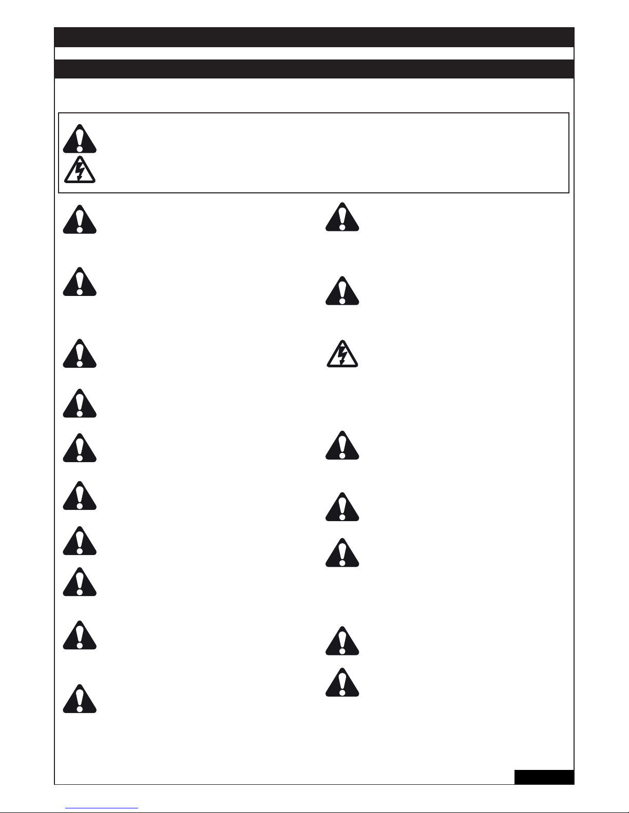
1/16 de
WARNUNG / ACHTUNG
WICHTIGE ANWEISUNGEN ZUR MONTAGE UND NUTZUNG
BEGINNEN SIE MIT DEM LESEN DIESER WICHTIGEN SICHERHEITSREGELN
Solche Warnzeichen bedeuten “Vorsicht!”, eine Aufforderung zur Beachtung, da ihre Mißachtung Personen- bzw.
Sachschäden verursachen kann. Bitte lesen Sie diese Warnungen sorgfältig.
Dieser Torantrieb ist so konstruiert und geprüft, daß er bei Installation und Benutzung unter genauer Befolgung
der anschließenden Sicherheitsregeln angemessene Sicherheit bietet.
Die Nichtbeachtung der folgenden Sicherheitsregeln kann ernsthafte Personen- oder Sachschäden verursachen.
Beim Umgang mit Werkzeugen und Kleinteilen
Vorsicht walten lassen und weder Ringe, Uhren
noch lose Kleidungsstücke tragen, wenn Sie
Installations- oder Reparaturarbeiten an einem
Tor vornehmen.
Elektrische Leitungen sind entsprechend den
lokalen Bau- und Elektroinstallationsvorschriften zu verlegen. Das elektrische Kabel darf nur
von einer autorisierten Elektrofachkraft an ein
ordnungsgemäß geerdetes Netz angeschlossen
werden.
Bei der Montage muß ein Einklemmen zwischen
dem angetriebenen Teil und den umgebenden
Teilen des Gebäudes (z.B. eine Wand) aufgrund
der Öffnungsbewegung des angetriebenen Teils
vermieden werden.
Entfernen Sie bitte alle am Tor angebrachten
Schlösser, um Schäden am Tor zu vermeiden.
Nach der Installation ist zu prüfen, ob der
Mechanismus richtig eingestellt ist und ob der
Antrieb, das Sicherheitssystem und die
Notentriegelung richtig funktionieren.
Ist ein Gehtor im Tor vorhanden, darf der Antrieb
nicht starten oder weiter laufen, wenn das Tor
nicht ordnungsgemäss geschlossen ist.
Beim Betrieb darf das Tor unter keinen
Umständen öffentliche Durchgangswege
behindern.
Zur Vermeidung von Schäden an sehr leichten
Toren ist eine entsprechende Verstärkung
anzubringen. Wenden Sie sich hierzu
bitte an den Hersteller des Tores.
Betätigen Sie den Antrieb nur, wenn Sie das Tor
voll im Blickfeld haben und sich dort keine
behindernden Gegenstände befi nden. Kinder
sollten nicht in Tornähe bei Betätigung des
Antriebes spielen.
Feuchtigkeit und Wasser zerstören die
Steuerung. Stellen Sie unter allen Umständen
sicher, dass Wasser, Feuchtigkeit oder
Staunässe nicht in die Steuerungsabdeckung
gelangen können.
Es ist wichtig, das Tor immer gut gangbar zu
halten. Tore, die steckenbleiben oder
verklemmen, sind unverzüglich zu reparieren.
Versuchen Sie nicht, das Tor selbst zu
reparieren. Bestellen Sie hierfür einen
Fachmann.
Entfernen Sie zusätzliches Zubehör aus der
Nähe von Kindern. Erlauben Sie Kindern nicht,
Drucktaster und Fernbedienungen zu bedienen.
Schwere Verletzungen können durch ein sich
schließendes Tor verursacht werden.
Automatisch gesteuerte Geräte müssen vom
Netz getrennt werden, wenn Wartungsarbeiten
wie zum Beispiel Reinigung ausgeführt werden.
In der festverlegten Installation ist eine Trennvorrichtung vorzusehen, um ein allpoliges
Abschalten mittels Schalter (mind. 3mm
Kontaktöffnungsweg) oder separate Sicherung
zu gewährleisten.
Stellen Sie sicher, daß Personen, die den Antrieb
montieren, warten oder bedienen, diesen
Anleitungen folgen. Bewahren Sie die Anleitung
an einem Ort auf, an dem schnell auf sie
zurückgegriffen werden kann.
Der endgültige Schutz vor Quetsch- und
Scherstellen muss nach der Montage des
Antriebes mit dem Tor gewährleistet sein.
Diese Anlage darf nicht von Personen bedient
werden (einschliesslich Kindern), die körperlich
oder geistig beeinträchtigt sind, oder denen es
an Erfahrung im Umgang mit der Anlage mangelt, solange sie nicht unter Aufsicht sind oder
von einer für ihre Sicherheit verantwortlichen
Person im Umgang mit der Anlage unterwiesen
worden sind.
Kinder sollten beaufsichtigt werden um
sicherzustellen, dass sie nicht mit der Anlage
spielen.
Automatischer Torantrieb - Nicht im Torbereich
aufhalten, da das Tor unerwartet betrieben
werden könnte.
Diese Anleitung ist aufzubewahren!
Page 52
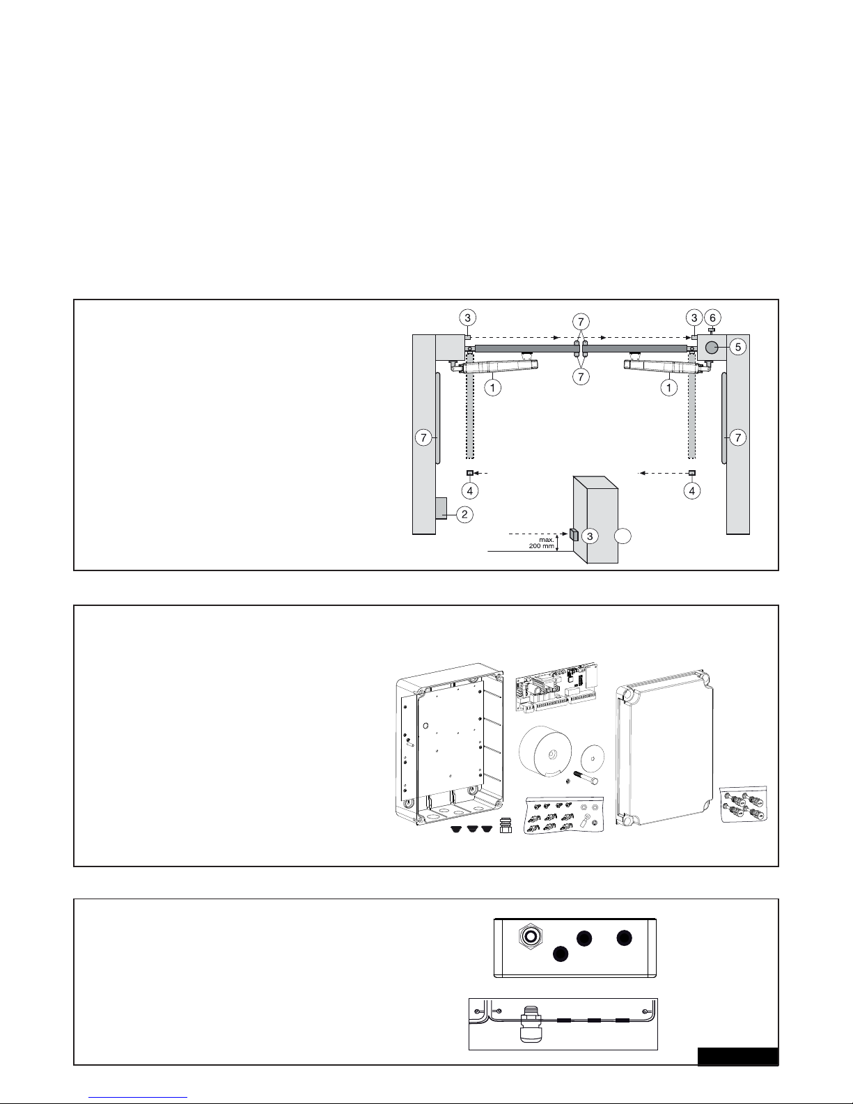
TECHNISCHE DATEN DER MOTORSTEUERUNG
Spannung: 230V~+/- 10% 50-60Hz
Transformator: 230/24VAC, 150VA
Ausgang Motor: 24VDC
Verbrauch max.: max. 400W (in Betrieb)
Verbrauch Standby: max. 4W (ohne Zubehör)
Versorgung Zubehör: 24VDC / 600mA max.
Arbeitstemperatur: -20ºC ÷ +55ºC
Arbeitsweise: Standard, Automatik
Abmessungen: 250x75mm (ohne Box)
Abmessungen Box: ca. 300x220x120mm
Schutzgrad: IP45
Sicherung: 2 x 2A (fl ink)
Handsender: max. 170 x Rolling Code
mögliche Frequenzen: 433MHz, 868MHz
TYPISCHER AUFBAU EINER ANLAGE:
1. Motor
2. Steuerung
3. Lichtschranke (aktiv in Schließen), Höhe max. 200 mm
Erste Lichtschranke.
4. Lichtschranke (aktiv in Öffnen/Schließen), Höhe max. 200 mm
Zweite Lichtschranke (optional).
5. Blinkleuchte (optional)
Wichtiger optischer Hinweis auf die Bewegung des Tores.
6. Schlüsselschalter oder Codeschloss (optional)
Wird an der Aussenseite angebracht. Mittels Schlüssel
oder Eingabe einer Nummer wird das Tor geöffnet.
7. Kontaktleiste (optional)
Sichert das Tor bei Berührung ab. Kontaktleisten können
am Tor oder an den Pfeilern angebracht werden .
Kontaktleisten müssen, wenn erforderlich, bis zu einer
Höhe von 2,5 m angebracht werden.
2/16 de
MONTAGE DER STEUERUNGSBOX
Die Steuerung besteht aus mehreren Komponenten.
- Gehäuse 1
- Deckel für Gehäuse 1
- Steuerung 1
- Transformator 1
- Montageplatte (vormontiert) 1
- Zugentlastung groß 1
- Zugentlastung klein 3
- Halteclips 6
- Schrauben 3,5mm x 9,5mm 4
- große Unterlegscheibe 1
- lange Schraube 1
- Kabelöse 1
- Mutter M8 2
- Unterlegscheibe M8 1
- große Verschlussschrauben 5
VORBEREITEN DER STEUERUNGSBOX
Öffnen Sie z.B. mit einem Schraubendreher die
4 Löcher im Boden des Gehäuses. Die große
Zugentlastung links befestigen, die restlichen wie
gezeigt. Feuchtigkeit und Wasser zerstören die
Steuerung. Alle Öffnungen und Zugentlastungen
müssen unbedingt wasserdicht verschlossen sein.
Die Steuerungsbox mit der Motorsteuerung ist mit
den Zugentlastungen nach unten zu montieren.
4
+
Page 53

EMPFOHLENE VORGEHENSWEISE
Erforderliche Abstände abmessen und passende Bohrlöcher bestimmen. Gehäuse an die Wand schrauben (Befestigungsmaterial nicht
enthalten). Die Montageplatte ist bereits im Gehäuse montiert. (A)
Halteclips in die vorgesehen Löcher eindrücken. (B)
Steuerung auf die Halteclips drücken. (C)
Den Transformer mit der großen Schraube und der großen Unterlegscheibe auf die Montageplatte schrauben. (D)
Die 4 Verschlussschrauben durch die Öffnungen im Deckel drücken und diesen auf das Gehäuse aufsetzen. Zwei Verschlussschrauben (links
oder rechts) etwa 2cm eindrehen. Danach kann man den Deckel zur Seite klappen. (E)
Schliessen Sie das Gehäuse versuchsweise indem Sie alle Schrauben komplett eindrehen. Sollte hierbei der Deckel das Gehäuse nicht
vollständig schliessen, ist dieses nicht ebenmässig an die Wand montiert und somit verformt. Korrigieren Sie den Sitz des Gehäuses, da der
wasserdichte Verschluss gewährleistet sein muss.
3/16 de
6x
B
C
D
A
E
Page 54

VERKABELN DER STEUERUNG / ÜBERSICHT:
a. Beginnen Sie mit dem noch spannungslosen 230Volt
Zuleitungskabel an der linken Seite der Box.
b. Kabelöse am Erdungsleiter anbringen.
Verbinden Sie den Erdungsleiter der Zuleitung mit der Grund platte (wie im Bild gezeigt). Schließen Sie alle anderen Kabel
an die Steuerung an.
KABEL UND VERDRAHTUNG
Der Gebrauch abgeschirmter Kabel vom Motor zur Steuerung ist empfehlenswert.
Magnetischer und induktiver Einfl uss im Kabel kann Summen hervorrufen und die Funktion des Tores stören.
Vermeiden Sie generell:
- die Steuerung zu weit weg vom Tor anzubringen.
- 230Volt Und Niederspannungsleitungen zusammen zu verlegen. Nach Elektroinstallationsvorschrift nicht zulässig.
- Kabel für Lichtschranken, Schalter, Blinklampe und Elektroschloss nicht zusammen mit dem Motorkabel verlegen.
- Telekommunikationskabel oder Leitungen für Gartenbeleuchtung ebenfalls nicht mit dem Motorkabel verlegen.
- Starre Kupferkabel sind speziell bei größeren Kabeldurchmessern schwer zu verdrahten. Benutzen Sie fl exibele Kabel.
- Benutzen Sie Kabel, die für aussen und die Verlegung im Erdreich geeignet sind oder entsprechende Leerrohre oder fragen Sie ihren Elektriker.
Wir empfehlen das folgende Zubehör:
- LA400-JB40E Kit Kit zur Kabelverlängerung für eine Anlage. Bestehend aus 12m Kabel, 6-polig mit gleichen Farben wie Antrieb, Verteilerdose
IP65, Kabelverschraubungen und Befestigungsmaterial.
- 041ASWG-0482-50 50m Ring Anschlusskabel, 6-polig für den Aussenbereich. Verlegung ohne Leerrohr möglich. Mit gleichen Farben wie am
Antrieb.
Kabelgrößen:
Die Abmessungen in der Tabelle sind Mindestgrößen. Größere Durchmesser sind jederzeit möglich
- 230Volt Versorgungsspannung für die Steuerung: min. 0,75mm² 3-polig
- 230Volt Versorgung für Transformator getrennt installiert (e.g. in der Garage) und Kleinspannung zum Tor. Siehe Tabelle.
- Motorverkabelung: 2 Kabel min. 1,0mm², 4 Kabel min. 0,75mm² (oder abgeschirmte Kabel)
- Elektrisches Schloss: Siehe Tabelle
- Schalter, Lichtschranken, Blinklampe: Siehe Tabelle etc. min.0,5mm²
4/16 de
Antriebsmodell
LYN, SCS, ART
Motorverkabelung
SUB (Unterfl urantrieb)
Motorverkabelung
Separat installierter
Transformator (in der
Garage) und Niederspannungsversorgung
der Steuerung
Elektroschloss (12Volt)
Verkabelung
Externe Antenne
(Entfernen Sie die
Originalantenne von der
Steuerung)
Schalter, Blinklampe etc.
Lichtschranke
Entfernung
0m - 6m
2 x 1,0mm²
4 x 0,75mm²
2 x 1,0mm²
3 x 0,75mm²
0,75mm²
0,75mm²
Koaxialkabel
50 Ohm
0,5mm²
0,5mm²
Entfernung
6m - 10m
2 x 1,0mm²
4 x 0,75mm²
2 x 1,0mm²
3 x 0,75mm²
0,75mm²
0,75mm²
Koaxialkabel
50 Ohm
0,5mm²
0,5mm²
Entfernung
10m - 12m
Normal
Verkabelung
Abgeschirmte Kabel für
die 3 kleineren
Motorkabel benutzen
1,0mm²
1,0mm²
Koaxialkabel
50 Ohm
0,75mm²
0,75mm²
Entfernung
12m – xx
Max. 15m
Abgeschirmte Kabel für die 4
kleineren Motorkabel benutzen
Abgeschirmte Kabel für die 3
kleineren Motorkabel benutzen
Max. 30m; Min. 1,5mm²
Torgewicht maximal 50% der
maximalen Motorleistung
Max. 30m; Min. 1,5mm²
Koaxialkabel
50 Ohm
(max. 25m)
Min. 0,75mm²
Max. 30m
Min. 0,75mm²
Max. 20m
Page 55

5/16 de
ANSCHLUSSPLAN
LYN/SCS
230VAC
PE
PE
Model
203285
Ω
8.2
+
+
+
+
+
+
+
Relay
+++
+
-
RED
RED
BLUE
BLUE
Model
CM475
BROWN
GREEN
WHITE
BROWN
GREEN
WHITE
YELLOW
YELLOW
RADIO MODULE
Model
207399
230 VAC
50
RED
RED
BLUE
BLUE
BROWN
GREEN
WHITE
BROWN
GREEN
WHITE
not required
not required
RED
RED
BLUE
BLUE
BROWN
GREEN
WHITE
BROWN
GREEN
WHITE
YELLOW
YELLOW
ART
SUB
Closed position
Open position
externe
Batterie
Page 56
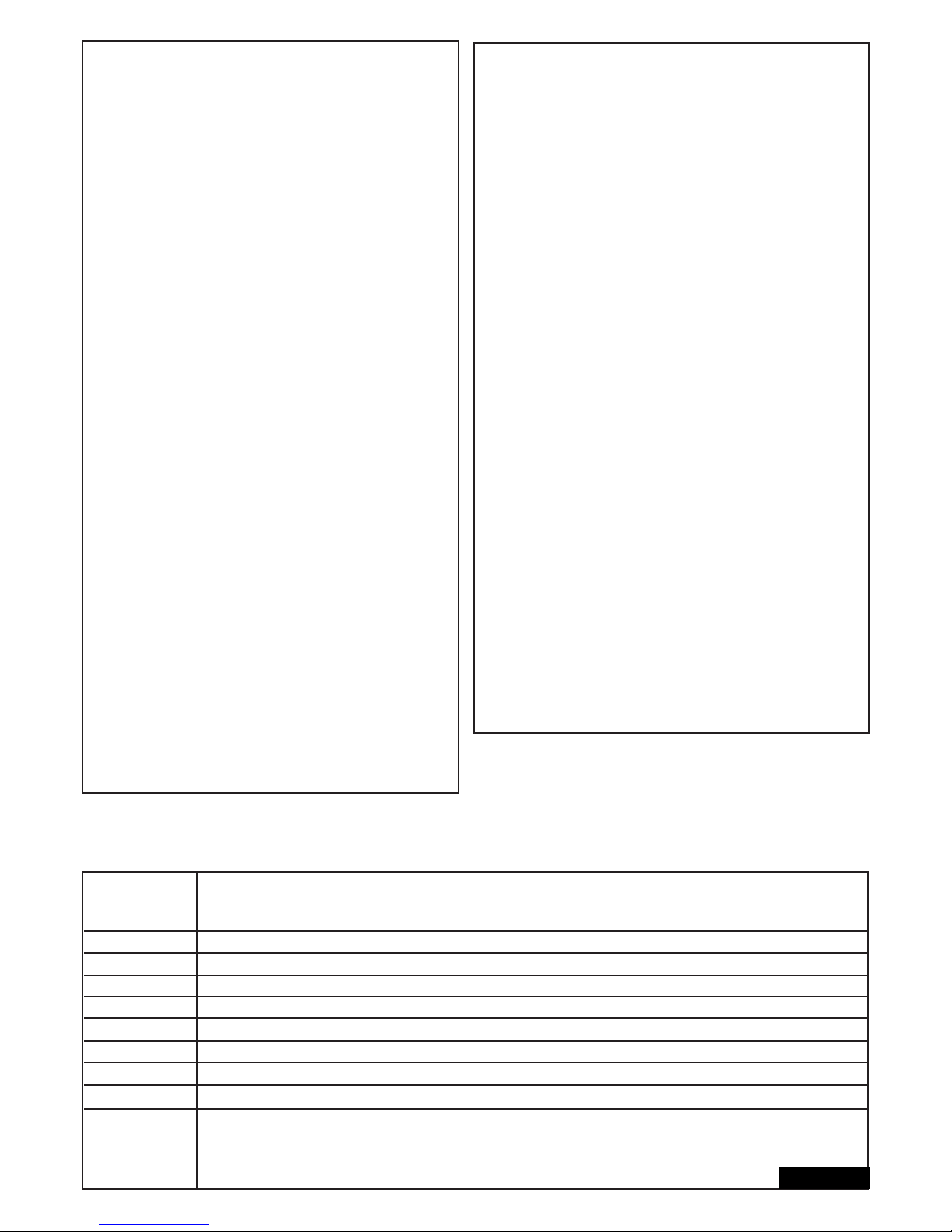
Funktionen der Drucktaster P1, P2, P3 & RESET
P1+P2+P3
P1
P1 + P2
P2 + P3
P1 + P3
P2
P3
DIP „RADIO“ + P1
DIP „RADIO“ + P2
RESET
Einzelbetrieb. Die Flügel können einzeln bewegt werden. FunKtion aktivieren: P1+P2+P3 gleichzeitig drücken. Die LEARN-LED
blinkt solange die Funktion aktiviert ist. Taste P1 bewegt Motor1. Taste P2 bewegt Motor2. Funktion deaktivieren: 20
Sekunden warten oder die Steuerung abklemmen. Wenn die Flügel zuerst schliessen, vertauschen Sie die Kabel rot und blau.
Programmiert automatisch die Endpositionen des Laufwegs
Programmiert automatisch die Endpositionen des Laufwegs (sowie zusätzliche Positionen z.B. Soft-Start und Soft-Stop).
Verzögerung Elektroschloss
Einstellung der Flügelverzögerung
Automatisch Schliessen. Zum Bestätigen Taste P2 notwendig
Software-Reset zur Werkseinstellung. Taste 10 Sekunden lang drücken. Das Reset betrifft nicht den Funkspeicher (siehe Funk)
Programmierung der Handsender für Kanal 1. Signal für komplettes Öffnen
Programmierung der Handsender für Kanal 2. Signal für teilweises Öffnen
Internet Schnittstelle oder Torüberwachung programmieren: Hinweis: Die RESET Taste führt kein Reset zur Werkseinstellung
bei dieser Steuerung aus. Sie dient einzig zum Programmieren der Internet Schnittstelle oder der Torüberwachung.
Siehe Beschreibung der Taste P3 für ein Reset zur Werkseinstellung.
Taste Funktion
6/16 de
BESCHREIBUNG DER ANSCHLÜSSE
BESCHREIBUNG FUNKTION
L Anschluss L 230Volt Zuleitung
N Anschluss N 230Volt Zuleitung
30VDC Anschluss einer externen Batterie
Motor MASTER Motor 1 (Master, öffnet als erster)
Motor SECOND Motor 2 (Second, öffnet als zweiter)
Zur Überprüfung der korrekten Polarität siehe Abschnitt
“Grundeinstellung” und “Funktion der Drucktaster P1,P2,P3 & RESET”
24V /150mA Blinkleuchte (Zubehör)
MASTER Motor1
BRN Kabel Braun
GRN Kabel Grün
WHT Kabel Weiss
YEL Kabel Gelb
SECOND Motor2
BRN Kabel Braun
GRN Kabel Grün
WHT Kabel Weiss
YEL Kabel Gelb
Light Contact Torüberwachung/Gartenbeleuchtung
PED Anschluss Schlüsselschalter
COM Minuspol
STOP Notaus / Stopschalter
„Schlüsselsymbol“ Schlüsselschalter
COM Minuspol
PHOTO 3 Lichtschranke 3 (öffnen)
PHOTO 2 Lichtschranke 2 (schliessen & öffnen)
PHOTO 1 Lichtschranke 1 (schliessen)
COM Minuspol
EDGE Kontaktleiste mit 8,2kOhm
8,2KOhm
„Symbol“ E-Schloss Eingang Elektroschloss „Steuereingang“
INPUT 24VAC 24Volt Eingangspannung vom Trafo.
Kann mit beliebiger Polarität
angeschlossen werden
Transformer 230VAC 230Volt Zuleitung zumTransformator.
Kann mit beliebiger Polarität
angeschlossen werden.
250V/2A Sicherung 250V/2A (2x fl ink)
BESCHREIBUNG DER LEDs
BESCHREIBUNG FARBE FUNKTION
STOP Grün Notaus
AN: Notaus aktiv
AUS: OK (Drahtbrücke, wenn kein
Schalter angeschlossen)
EDGE Grün Kontaktleiste 8.2KOhm
AN: aktiviert
AUS: OK (brücken mit 8,2KOhm Widerstand,
wenn keine Kontaktleiste angeschlossen)
„Schlüsselsymbol“ Rot Schlüsselschalter 2-Flügel
AN: Schalter betätigt
AUS: Schalter nicht betätigt
PED Rot Schlüsselschalter 1-Flügel
AN: Schalter betätigt
AUS: Schalter nicht betätigt
PHO1 Rot Lichtschranke 1 (schliessen)
AN: OK (aktiv)
AUS: keine Lichtschranke
PHO2 Rot Lichtschranke 2 (öffnen & schliessen)
AN: OK (aktiv)
AUS: keine Lichtschranke
PHO3 Rot Lichtschranke 3 (öffnen)
AN: OK (aktiv)
AUS: keine Lichtschranke
LEARN Gelb Lernprogramm Status
AN: Lernprogramm aktiv
AUS: Kein Lernprogramm
DGN Rot Diagnose-Programm (siehe Seite 15)
CH1 Rot Programmierung der Handsender für
2-Flügelbetrieb
AN: Neuer Handsender kann
programmiert werden
AUS: Funktion aus
CH2 Rot Programmierung der Handsender für
1-Flügelbetrieb (siehe CH1)
Page 57

7/16 de
OPTIONALES ZUBEHÖR (siehe auch Anschlussplan)
FUNKSTEUERUNGEN (OPTIONAL) MODELLE:
TX2EV, TX4EV, TX4UNI (Handsender), 747EV (Funkcodeschloss), 128EV (Funkwandkonsole)
BLINKLAMPE (OPTIONAL) Modell: FLA24-2, FLA1-LED
Eine Blinkleuchte kann an die Steuerung angeschlossen werden (Anschlüsse: 24 VDC / 150 mA). Sie warnt Personen vor dem sich
bewegenden Tor. Die Blinkleuchte sollte möglichst hoch und deutlich sichtbar angebracht werden. Die Steuerung liefert ein konstantes Signal,
welches von der Lampe in ein Blinksignal umgewandelt wird.
SCHLÜSSELSCHALTER (OPTIONAL) Modell: 100010, 100027, 100034, 100041
Die Anlage kann mit einem Schlüsselschalter betrieben werden. (Anschlüsse: Schlüsselsymbol und COM)
Siehe auch OPEN/PED unter „DIP Schalter“.
NOTAUS / STOPSCHALTER (OPTIONAL) Modell: 600084
Ein Notaus-Schalter, der das Tor in jeder Richtung anhält, kann an diesen Eingang angeschlossen werden.
KONTAKTLEISTE (OPTIONAL) Modell: 600046, 600053, 600077, 600060
(DIP-Schalter LOOP/EDGE muss aus sein)
An die Steuerung kann eine Kontaktleiste, die nach dem 8,2K Ohm- Prinzip funktioniert, angeschlossen werden, d.h., ein 8,2K Ohm großer
Prüfwiderstand ist am Ende der Kontaktleiste befestigt. Er gewährleistet die ständige Überprüfung des Stromkreises. Die Steuerung wird mit einem
eingebauten 8,2K Ohm Widerstand ausgeliefert. Mehrere Kontaktleisten werden in Reihe geschaltet.
LICHTSCHRANKE (OPTIONAL) MODELLE 771E, 772E:
Der Gebrauch einer Lichtschranke wird empfohlen. Benutzen Sie Modell 771E oder 772E, welches auch Bestandteil des Safety Accessory Kit
APLUS- EV ist.
SAFETY ACCESSORY KIT (OPTIONAL): APLUS-EV
Die Steuerung ist bereits mit einer Standard-Antenne ausgestattet. Für höhere Reichweiten kann eine externe Antenne aus dem
APLUS-EV Zubehör (beinhaltet Lichtschranke 771E, Blinklampe FLA1-LED und Externe Antenne SWG-ANT-EV) wie in der Anschlussübersicht
dargestellt, angeschlossen werden.
myQ (OPTIONAL)
(nur mit Internet Schnittstelle 828EV):
Erlaubt das Bedienen des Tores per Internet oder Smartphone.
TORÜBERWACHUNG (OPTIONAL)
(nur mit Torüberwachung 829EV):
Erlaubt optische und akustische Überwachung der Torposition. Das Tor kann mit diesem Gerät auch geschlossen werden.
BATTERIE (OPTIONAL)
Die Anschlüsse dienen zum Aufl aden einer externen Batterie.
Im Falle eines Stromausfalls versorgt die Batterie den Antrieb mit Energie. Eine voll aufgeladene Batterie kann Energie für mehr als 24h liefern.
Batterien unterliegen der Alterung und verlieren an Kapazität. Tauschen Sie die Batterie je nach Gebrauch alle 2-3 Jahre aus.
ELEKTROSCHLOSS (OPTIONAL)
Die Steuerung bietet die Möglichkeit, ein 12V Elektroschloss zu betreiben. (Anleitung liegt dem E-Schloss bei). Hierzu muss eine Hilfssteuerung
(207399) für das Elektroschloss an der Hauptsteuerung angeschlossen werden. Falls das E-Schloss durch zu viel Druck des Tores nicht öffnet,
kann eine spezielle Funktion programmiert werden: Drücken Sie P2 und P3 gleichzeitig für ca. 5 Sekunden und zählen Sie die hörbaren Klicks.
1Klick = ca. 4 Sekunden Strom zum E-Schloss (Werkseinstellung)
2 Klicks = Tor schliesst für eine Sekunde und öffnet dann. Ferner, nach erreichen der Position Tor geschlossen, drückt der Antrieb kurz um das
Einrasten des Elektroschlosses zu unterstützen. Hinweis: Das Tor muss dazu mit Bodenanschlägen ausgerüstet sein.
TORÜBERWACHUNG ODER BELEUCHTUNG (OPTIONAL)
Die Anschlüsse haben zwei Funktionen abhängig davon ob der DIP Schalter Light / Spy an ist oder nicht. Siehe auch unter
“DIP Schalter” in dieser Anleitung. Der Ausgang hat keine eigene Stromversorgung und darf nur bis 24V belastet werden.
Torüberwachung / Status des Tores (Spy)
Eine LED, eine Lampe (24V / 3W max.) oder ein Relais können an die Klemmen angeschlossen werden, um den Status des Tores anzuzeigen.
LED aus = Tor geschlossen
LED langsam blinkend = Tor öffnet
LED an = Tor offen
LED schnell blinkend = Tor schliesst
Hofbeleuchtung / Beleuchtung für 120 Sekunden
Eine Lampe (24V / 3W max.) oder ein Relais können an die Klemmen angeschlossen werden.
Wenn die Steuerung ein Signal zum Öffnen oder Schliessen bekommt, leuchtet die Lampe für 120 Sekunden und schaltet sich danach automatisch
aus.
Achtung: nur max. 24V/3W an den Klemmen anschliessen oder ein Relais muss dazwischengeschaltet werden.
Page 58

8/16 de
LICHTSCHRANKEN (OPTIONAL) MODELL: 771E, 772E
Die Lichtschranken dienen der Absicherung des Tores und müssen verwendet werden.
Der Montageort ist abhängig von der Bauweise des Tores. Nach EN12453 muß ein
Lichtschrankenpaar aussen in einer Höhe von 200mm aktiv in „Schliessen“ installiert
werden. Die Lichtschranken bestehen aus einem Sender und einem Empfangsteil und
müssen einander gegenüber liegen. Die Lichtschranke wird mittels kleiner Schrauben
und Dübel an der Wand befestigt. Soll die Funktion „Automatisches Schliessen“ möglich
sein, muss die Chamberlain – Failsafe Lichtschranke installiert sein. Das Chamberlain
–Failsafe System (2-Kabel System) besitzt an beiden Seiten eine kleine von außen
einsehbare LED (Licht), um den Status der Lichtschranke anzuzeigen.
Programmierung der Lichtschranke:
- Lichtschranke anschließen
- Wegstreckenprogrammierung der Torfl ügel durchführen
Löschen einer Lichschranke aus der Steuerung:
Eine angeschlossene Lichtschranke kann nicht entfernt werden ohne dass die
Steuerung die Funktion an dem jeweiligen Anschluss sperrt. Um die Lichtschranke aus
dem Programm der Steuerung zu löschen.
- Lichtschranke entfernen
- Strom kurz ausschalten
- Wegstreckenprogrammierung der Torfl ügel durchführen.
Diagnose an der Chamberlain-Failsafe Lichtschranke
LED konstant = OK
LED blinkt = Lichtschranke sperrt Steuerung
LED aus = Kein Strom, falscher Anschluss oder verpolt
Diagnose an der Steuerung
LED aus = OK, keine Lichtschranke angeschlossen
LED blinkt = Steuerung sperrt
Anschluss 1 & COM
Aktiv, wenn das Tor schliesst (reversiert das Tor)
Anschluss 2 & COM
Aktiv, wenn das Tor schliesst und öffnet
Anschluss 3 & COM
Aktiv, wenn das Tor öffnet
(das Tor bleibt solange stehen, bis das Hinderniss aus
dem Infrarotstrahl entfernt wird, danach bewegt es sich weiter)
FUNK
PROGRAMMIEREN / LÖSCHEN VON FRNBEDIENUNGEN
Der Empfänger besitzt 2 Kanäle CH1 und CH2. Die Benutzung der beiden
Kanäle ermöglicht sowohl einfl ügeligen als auch zweifl ügeligen Betrieb.
Beispiel: Erhält CH2 = P2 das Signal der Fernbedienung öffnet sich nur 1
Flügel. Benutzen Sie einen weitere Taste der Fernbedienung mit CH1 = P1
werden beide Flügel geöffnet.
PROGRAMMIERUNG
1: Dip-Schalter “RADIO” anschalten.
2: Drücken Sie kurz die Taste P1(für CH1) oder P2(für CH2) und die
jeweilige LED leuchtet auf.
3: Halten Sie nun die gewünschte Taste auf Ihrer Fernbedienung gedrückt
bis die LED nach kurzem Blinken erlischt. Fertig! Wiederholen Sie diese
Schritte für alle Fernbedienungen (maximal 85 Fernbedienungen
können pro Kanal eingelernt werden).
Wichtig: Nach Programmierung Ihrer Fernbedienung(en) den DIP-Schalter
“RADIO” wieder ausschalten!
Hinweis: Stellen Sie sicher, dass Sie nicht die gleiche Taste Ihrer Fernbedienung auf CH1 und CH2 einlernen; sonst funktioniert die Anlage nicht richtig.
LÖSCHEN
- DIP-Schalter “RADIO” anschalten.
- Halten Sie die Taste P1 so lange gedrückt bis die aufl euchtende LED
nach etwa 10 Sekunden erlischt. Fertig!
Zur Bestätigung blinken beide Leds CH1 und CH2 8 mal.
- DIP-Schalter „RADIO“ ausschalten.
RADIO MODUL
E
ON ON
RADIO MODUL
E
ON ON
RA
ON ON
RA
ON ON
+
+
+
+
+
+
+
+++
Page 59

9/16 de
PROGRAMMIEREN DER INTERNET SCHNITTSTELLE myQ
Mit der RESET-Taste auf der Steuerung
1. Die Liftmaster Internet Schnittstelle und ihren Router mit dem Netzwerkkabel
verbinden.
2. Die Liftmaster Internet Schnittstelle mit Strom versorgen.
3. Einen Online Account mit der neuesten Liftmaster myQ Smartphone App oder
auf www.liftmaster.eu einrichten.
4. Die Liftmaster Internet Schnittstelle registrieren.
5. Auf „Neues Gerät hinzufügen“ klicken und den Schritten der App oder der
Webseite weiter folgen.
6. Hinweis: Wenn Sie die RESET-Taste drücken werden Sie einen Piepton hören
und die LEDs CH1 und CH2 zunächst angehen und dann, nach erfolgtem
Abgleich, dreimal blinken und ausgehen.
7. Die App zeigt Ihnen an, ob die Programmierung erfolgreich war und wird Sie
auffordern, einen Namen für das Tor zu vergeben.
PROGRAMMIERUNG DER TORÜBERWACHUNG
Mit der RESET-Taste auf der Steuerung
1. Die Torüberwachung mit Strom versorgen und im Haus so positionieren, dass
sie gut sichtbar ist. Ist der Aufstellort zu weit vom Tor entfernt, kann die
Verbindung gestört oder oft unterbrochen sein. Positionieren Sie das Gerät
an einem besser geeigneten Aufstellort.
2. Die „LEARN“ Taste auf der Rückseite der Torüberwachung kurz drücken und
loslassen. Die rote und grüne LED blinken abwechselnd. Innerhalb 60 Sek
die RESET-Taste auf der Steuerung drücken und loslassen. Zur Bestätigung
der Programmierung gehen die rote und grüne LED an.
Torüberwachung löschen
Die „LEARN“ Taste auf der Rückseite der Torüberwachung für mindestens
10 Sek drücken.
Ein kurzer Piepton bestätigt das erfolgreiche Löschen.
ADIO MODULE
ADIO MODULE
Page 60

SCHLEIFENDETEKTOREN
(DIP Schalter LOOP/EDGE muss an sein.)
Schleifendetektoren reagieren auf Metall und werden zumeist zur
Erkennung von PKWs und LKWs, aber nicht von Motorrädern und
Fußgängern, eingesetzt.
Ausgangs-Schleife A
Die Ausgangs-Schleife befi ndet sich hinter dem Tor und öffnet das
Tor wenn es geschlossen ist, hält es offen oder öffnet es erneut.
Die DIP Schalter OPEN/STEP und LOOP/EDGE müssen
an sein. Lichtschranken müssen angeschlossen und die
Funktion “Automatisch Schliessen” aktiviert sein.
Sicherheits-Schleifendetektor und
Schleifendetektor im Schwenkbereich des Tores B, C
Schleifendetektoren dienen der Erkennung von Fahrzeugen (PKW,
LKW, aber sind als alleinige Schutzmassnahme unzulässig, da sie
Personen nicht erkennen.
Die Auswerteeinheit der Schleifendetektoren wird als NO
Signalgeber an die Klemmen der 8.2kOhm Kontaktleiste
angeschlossen. Falls Sie auch Kontaktleisten verwenden wollen:
Prüfen Sie vor der Installation welche Funktionsweise für sie
passend ist.
Sicherheits-Schleifendetektor
=> DIP Schalter OPEN/STEP muss an sein.
Schleifendetektor im Schwenkbereich des Tores
=> DIP Schalter OPEN/STEP ausschalten
Weitere Optionen für Schleifendetektoren können bei unserem
Service angefragt werden.
10/16 de
RN WHT YEL
ASTER
BRN GRN WHT YEL
SECOND
COM
PHOTO
3 2 1
C
LIGHT
CONTACT
PED
COM
STOP
NO
Model
203292
Model
203292
RN WHT YEL
ASTER
BRN GRN WHT YEL
SECOND
COM
PHOTO
3 2 1
COM EDGE
8.2KΩ
LIGHT
CONTACT
PED
COM
STOP
NO
COM
NC
A
B
C
A
B C
RADIO
ON ON
RADIO
MOD
ON
RADIO
MOD
ON
Page 61

DIP SCHALTER
1 / 2 MOTOR
Wählt aus, ob 1 oder 2 Motoren an der Steuerung angeschlossen sind
AUS: 2 Motoren angeschlossen
AN: 1 Motor angeschlossen
OPEN/STEP
Ändert die Programmierung und Reaktion der Steuerung auf Signale.
Für den Gebrauch mit Schleifendetektoren lesen Sie bitte erst unter
“Schleifendetektoren” nach.
Schritt-Modus: Das erste Signal öffnet das Tor, das nächste stoppt, das
nächste schliesst, das nächste stoppt, das nächste öffnet usw...
Öffnen-Modus: Das Tor wird nicht auf Steuersignale reagieren, solange
es öffnet und die Position OFFEN erreicht hat.
AUS: Schritt-Modus
AN: Öffnen-Modus
LIGHT/SPY
Nur anschalten, wenn die Funktion benötigt wird, ansonsten aus lassen
AUS: LIGHT
AN: SPY
OBSTACLE
Werkseitig mit fester Drahtbrücke ausgestattet. Durchtrennen erhöht
die Arbeitskraft an der Steuerung.
ACHTUNG: Wird die Drahtbrücke durchtennt, muss die Toranlage mit
zusätzlichen Sicherheitseinrichtungen (Kontaktleiste etc.) abgesichtert
werden.
LOOP/EDGE
Wählen Sie die gewünschte Funktion aus
AUS: Kontaktleiste
AN: Schleifendetektor
SPEED
Wählen Sie für den Motortyp aus, den Sie einsetzen wollen.
AUS: ART
AN: LYN, SCS, ART, SUB
RADIO
Der DIP Schalter “RADIO” ist zur Programmierung der Handsender
erforderlich. Den Programmierungsvorgang entnehmen Sie bitte dem
entsprechenden Abschnitt in dieser Anleitung.
AUS: keine Programmierung möglich
AN: Programmierung möglich
WICHTIG: Den DIP Schalter “RADIO” immer ausschalten,
wenn er nicht in Gebrauch ist.
FLÜGELVERZÖGERUNG
Die Flügelverzögerung ist notwendig zum korrekten und sicheren
Öffnen und Schliessen der Flügel. Eine längere Flügelverzögerung
kann erforderlich sein bei unterschiedlichen Installationsbegebenheiten
oder unterschiedlichen Flügellängen.
Drücken und halten Sie P3 und P1 zusammen für etwa 5 Sekunden
und zählen Sie die Anzahl der zu hörenden Klicks. Das Klicken wird
von einem Relais (Lichtrelais) verursacht.
1 Klick = kurze Verzögerung, ca. 4÷8 Sekunden (Werkseinstellung)
2 Klicks = mittlere Verzögerung, ca. 8÷12 Sekunden
3 Klicks = lange Verzögerung, ca. 12÷16 Sekunden
4 Klicks = komplette Verzögerung, Flügel 1 wird erst schliessen,
wenn Flügel 2 komplett geschlossen ist
Die Verzögerung in Öffnen ist immer ca. 3÷5 Sekunden
5 Klicks = keine Verzögerung, beide Flügel Öffnen und Schliessen gleichzeitig
Wiederholen Sie den Vorgang falls erforderlich.
HINWEIS: Programmieren (ändern) des Laufweges setzt die
Flügelverzögerung auf Werkseinstellung zurück.
11/16 de
RADIO MODULE
RADIO MODULE
ON ON
Page 62

12/16 de
ERSTE INBETRIEBNAHME
GRUNDEINSTELLUNG
Gehen Sie Punkt für Punkt genau durch. Beginnen Sie im Zweifelsfall wieder von vorne. Nehmen Sie sich für diese Einstellungen
ausreichend Zeit.
1. Ist alles Notwendige für den Betrieb angeschlossen? Motoren, Lichtschranken, Sicherheitskontaktleiste, Stop-Schalter.
2. Stellen Sie sicher, dass sich niemand im Torbereich aufhält oder aufhalten kann.
3. Schließen Sie das Tor und hängen Sie die Motoren ein. Sichern Sie die Motoren mit dem Splintbolzen und drehen Sie den
Entriegelungshebel in Richtung Torpfeiler. Die Antriebe sind verriegelt.
ART:
- für eine erfolgreiche Programmierung des Laufweges müssen die
Referenzpunkte eingestellt werden. Hierfür müssen die Nocken unter
der Haube des ART korrekt eingestellt werden. Die obere Nocke soll
den Mikroschalter zuerst auslösen, dann die untere.Die Mikroschlter
sollen nicht gleichzeitig ausgelöst werden oder wenn das Tor die
Endpunkte erreicht hat. Drehen Sie die Nocken mit Hilfe einer Zange
oder eines großen fl achen Schraubendrehers auseinander.
- entriegeln Sie das Tor für diese Einstellungen
- Kontrolle oder Korrektur der richtigen Position der Schalternocken wie
in der Anleitung gezeigt für Tor AUF und Tor ZU.
- Einstellung der DIP Schalter bei Verwendung des ART: DIP Schalter
“SPEED” ausschalten. Der ART wird nicht funktionieren, wenn “SPEED“
an ist.
SUB (Unterfl urantrieb):
- Einstellung der DIP Schalter: “SPEED” an für eine schnellere Torbewegung oder aus, wenn das Tor sehr schwer
ist oder ein sehr sicherer Betrieb erforderlich ist. Kann nach dem Fertigstellen der Installation jederzeit geändert werden.
LYN / SCS Antriebe:
- Einstellung der DIP Schalter: “SPEED” an für eine schnellere Torbewegung oder aus, wenn das Tor sehr schwer
ist oder ein sehr sicherer Betrieb erforderlich ist. Kann nach dem Fertigstellen der Installation jederzeit geändert werden.
Schließen Sie jetzt die Steuerung an das Stromnetz an.
GRUNDEINSTELLUNG:
1. Drücken Sie Taster P1, P2 und P3 gleichzeitig für 2-3 Sekunden, bis die gelbe LED blinkt.
2. Beobachten Sie das Tor. Drücken und halten Sie die Taste P1 für 1-2 Sekunden gedrückt. Das Tor mit Motor 1 muss sich dabei
in Richtung AUF bewegen. (Tor nicht ganz öffnen nur kurze Bewegungen fahren.) Schließt Motor 1 anstatt zu öffnen, ist er falsch
angeschlossen und die Kabel rot/blau am Motor müssen getauscht werden (Achtung: Steuerung vorher stromlos schalten!).
Hinweis: Generelle Funktion - wenn Sie den Taster loslassen, bleibt das Tor sofort stehen. Bei erneutem Drücken läuft es in die
entgegengesetzte Fahrtrichtung, bis Sie den Knopf wieder loslassen usw.
3. Drücken und halten Sie P2 für 1-2 Sekunden. Das Tor mit Motor 2 muss sich dabei in Richtung AUF bewegen. (Tor nicht ganz
öffnen nur kurze Bewegungen fahren.) Schließt Motor 2 anstatt zu öffnen, ist er falsch angeschlossen und die Kabel rot/blau am
Motor müssen getauscht werden (Achtung: Steuerung vorher stromlos schalten!).
Hinweis: Die Steuerung bleibt 20 Sekunden in diesem manuellen Einstellprogramm. Beginnen Sie ggf. wieder von vorne mit
dem gleichzeitigen Drücken der Tasten P1/P2/P3
Überprüfen Sie:
1. Nur bei SCS: Wenn der Flügel öffnet, darf die vordere „Nase“ des Motors das Tor NICHT berühren (stoßen oder schleifen). Das
Öffnen mehrfach unterbrechen und kontrollieren! Im Falle einer Berührung müssen Maß A/B kontrolliert werden und ggf. der
Torbeschlag unterlegt werden, um mehr Abstand zu erhalten.
2. Beide Flügel komplett öffnen. Nicht zu weit fahren! Wenn kein Anschlag in AUF vorhanden ist, markieren Sie den
maximalen Öffnungspunkt.
3. Nur bei SUB (Unterfl urantrieb): Justieren Sie jetzt die mechanischen Endanschläge in der Box.
Warten Sie, bis die Lern LED von alleine ausgeht (20 Sekunden nach dem letzten Tastendruck).
Closed position
Open position
Tor geschlossen
Tor offen
Page 63

13/16 de
PROGRAMMIERUNG DER WEGSTRECKEN EINFACH I
Hinweis: Endanschläge in ZU und AUF müssen vorhanden sein.
1. Die Flügel müssen geschlossen sein.
2. Drücken Sie die Taste P1 solange, bis der Flügel / Motor 1 zu öffnen beginnt. (LED “LEARN” blinkt)
Das Automatik-Programm beginnt (langsame Fahrt):
Flügel 1 fährt bis zum Anschlag AUF.
Flügel 2 fährt bis zum Anschlag AUF.
Danach fährt Flügel 2 bis zum Anschlag ZU und anschließend fährt Flügel 1 bis zum Anschlag ZU.
Wenn LED „LEARN“ erlischt, ist die Programmierung abgeschlossen
Hinweis: Schließen die Flügel anstatt zu öffnen, sind die Motoren falsch angeschlossen. Vertauschen Sie Rot und Blau.
PROGRAMMIERUNG DER WEGSTRECKE: EINFACH II
Hinweis: Wenn kein Endanschlag in Richtung AUF vorhanden ist, sollte der Flügel bei ca. 90° Öffnungswinkel gestoppt werden.)
1. Die Flügel müssen geschlossen sein.
2. Drücken Sie die Taste P1 solange, bis der Flügel / Motor 1 zu öffnen beginnt.
3. Drücken Sie die Taste P1, wenn der Flügel / Motor 1 Position Tor AUF erreicht hat. Der Flügel 2 startet.
4. Drücken Sie die Taste P1, wenn der Flügel / Motor 2 Position Tor AUF erreicht hat. Der Flügel 2 schließt dann
automatisch wieder. Danach schließt Flügel 1 automatisch.
5. Der Antrieb lernt die Position Tor ZU automatisch.
Auf Wunsch können Sie aber auch einen individuellen Punkt in Tor ZU lernen.
Drücken Sie die Taste P1 dann an der gewünschten Tor Zu Position für den jeweiligen Flügel.
Wenn LED „LEARN“ erlischt, ist die Programmierung abgeschlossen.
PROGRAMMIERUNG DER WEGSTRECKE „ADVANCED“ (INDIVIDUELL)
Hinweis: Die Taste P1 muss in diesem Progamm insgesamt 9x gedrückt werden.
Mit jedem Tastendruck wird eine Position (Zeit) gespeichert. Dadurch ist es möglich, Soft-Stopp (Langsamlauf) zu speichern, um
sich dem Tor oder der Anwendung indivudell anzupassen. Lange oder kurze Soft-Stopp Phasen sind möglich.
1. Die Flügel müssen geschlossen sein.
2. P1 und P2 gleichzeitig längere Zeit drücken (ca.5-6 Sek.), bis Flügel 1 startet (öffnet). Tasten loslassen!!
3. P1 wieder drücken; Soft-Stopp in AUF-Richtung für Flügel 1 beginnt ab dieser Position.
4. P1 wieder drücken; Endanschlag AUF erreicht. Automatisch startet jetzt Flügel 2.
5. P1 wieder drücken; Soft-Stopp in AUF-Richtung für Flügel 2 beginnt ab dieser Position.
6. P1 wieder drücken; Endanschlag AUF erreicht. Automatisch startet jetzt Flügel 2 und schließt.
7. P1 wieder drücken; Soft-Stopp in ZU-Richtung für Flügel 2 beginnt ab dieser Position.
8. P1 wieder drücken; Endanschlag in ZU-Richtung erreicht. Automatisch startet jetzt Flügel 1
9. P1 wieder drücken; Soft-Stopp ZU für Flügel 1 beginnt ab dieser Position.
10. P1 wieder drücken; Endanschlag ZU erreicht. ->Fertig
Hinweis: Erreicht ein Flügel einen Endanschlag und die Taste P1 wird NICHT gedrückt, fährt der Antrieb auf den Anschlag und lernt
diese Position selbständig.
Page 64

14/16 de
FERTIGSTELLEN DER INSTALLATION/PROGRAMMIERUNG:
Ist die Wegstrecke programmiert, können die Handsender eingelernt werden (siehe EINLERNEN /LÖSCHEN DER HANDSENDER).
1. Lassen Sie nun das Tor mittels Tastendruck des Handsenders oder eines angeschlossenen Tasters 2 vollständige Zyklen durchlaufen und
beobachten Sie den Ablauf. Schließen Sie das Tor wieder, OHNE dass Sie weitere eine Einstellung vorgenommen haben.
2. Sind alle Einstellungen getroffen worden, überprüfen Sie die Funktion der Lichtschranken, Taster, Blinkleuchte, Handsender, Zubehör etc.
3. Zeigen Sie allen Personen, die Umgang mit dem Tor haben, wie die Bewegungen des Tores ablaufen, wie die Sicherheitsfunktionen arbeiten
und wie das Tor entriegelt und von Hand betätigt werden kann
AUTOMATISCHES SCHLIEßEN DES TORES
Hinweis: Nur möglich mit angeschlossener und funktionsfähiger Lichtschranke (PHOTO + COM).
Es kann eine autmatische Schließzeit zwischen 2 Sekunden und 120 Sekunden gewählt werden.
Einstellen
1. P2 drücken und halten, bis die gelbe LED zu blinken beginnt.
2. Wenn die gelbe LED blinkt, zählen Sie die Öffnungszeit, die programmiert werden soll, ab.
3. Nach Ablauf der Wunschzeit drücken Sie P2 erneut. ->Fertig
Ausschalten
1. P2 drücken und halten, bis die gelbe LED zu blinken beginnt.
2. P3 drücken. Die gelbe LED geht aus. ->Fertig
BETRIEBSSKRAFT DES ANTRIEBS
Die Betriebskraft des Antriebs wird automatisch eingestellt, während
die Wegstrecke programmiert wird. Eine Veränderung (automatisch)
ist nur mit einer erneuten Programmierung der Wegstrecke möglich.
Klemmt das Tor durch Witterungseinfl üsse oder Veränderungen an
der Toranlage (z.B. durch Rost oder unzureichende Schmierung),
muss es ggf. gewartet werden.
Die Steuerung entspricht den neuesten EN-Richtlinien.
Eine dieser Richtlinien schreibt vor, daß die Schließkräfte an der
Torkante innerhalb der letzten 500mm vor Tor ZU nicht über 400 N (40 kg)
steigen dürfen . Größer als 500 mm darf die maximale Kraft an der
Torkante 1400 N (140 kg) betragen. Kann dies nicht sichergestellt werden,
ist unbedingt eine Kontaktleiste ggf. bis in eine Höhe von 2,5 m am Tor
oder am gegenüberliegenden Pfeiler anzubringen (EN12453).
ENTSORGUNG
Die Verpackung besteht aus umweltfreundlichen Materialien. Sie kann in den örtlichen Recyclebehältern entsorgt werden. Gemäß der
Europäischen Richtlinie 2002/96/EG über Elektro-Altgeräte muss dieses Gerät nach Verwendung ordnungsgemäß entsorgt werden um eine
Wiederverwertung der verwendeten Materialien zu gewährleisten.
Über die Möglichkeiten dieser Entsorgung informiert die Gemeinde oder Stadtverwaltung.
BATTERIEENTSORGUNG
Batterien und Akkus dürfen nicht im Hausmüll entsorgt werden. Sie können die Batterien nach Gebrauch
in unmittelbarer Nähe (z.B. im Handel oder in kommunalen Sammelstellen) unentgeltlich zurückgeben.
Batterien und Akkus sind mit einer durchgekreuzten Mülltonne sowie dem chemischen Symbol des
Schadstoffes bezeichnet, nämlich “Cd” für Cadmium, “Hg” für Quecksilber und “Pb” für Blei.
12VDC
Pb Cd Hg
Page 65

15/16 de
ANZEIGE DER “DIAGNOSTIC”-LED
Die Diagnose LED zeigt den zuerst aufgetretenen Fehler an. Sollten weitere Fehler auftreten werden diese möglicherweise nicht angezeigt.
Anzeige
1x blinken
2x blinken
3x blinken
4x blinken
5x blinken
6x blinken
7x blinken
8x blinken
9x blinken
10x blinken
11x blinken
12x blinken
13x blinken
14x blinken
15x blinken
Beschreibung
Antrieb 1 Kontaktfehler eines Steuerkabels zur
Steuerung.
Wie 1x blinken für Antrieb 2
Endpunkte Antrieb 2 wurden nicht akzeptiert.
A: Nach oder in der Lernfahrt: Antrieb 1 wurde nicht
weit genug geöffnet.
B: Kontaktfehler eines Steuerkabels zur Steuerung.
Kabel Gelb oder Weiss hat keinen oder sehr schlechten Kontakt.
Endpunkte Antrieb 1 wurden nicht akzeptiert.
Wegstrecke ist nicht programmiert in der Steuerung.
Kraft, die benötigt wird, um die Flügel zu bewegen,
ist zu hoch.
A: Tor ist defekt
B: Tor ist schwergängig
C: Tor bei Wind stehengeblieben.
Lichtschranke 1 sperrt die Funktion
A: Objekt blockiert die Lichtschranke
B: Ausrichtung der Linsen zueinander ist nicht exakt.
C: Spannungsversorgung zu den Lichtschranken ist
nicht ausreichend
Lichtschranke 2 sperrt die Funktion
Lichtschranke 3 sperrt die Funktion
Not-Aus Schalter sperrt die Anlage
Kontaktleiste sperrt die Anlage
A: Objekt drückt auf Kontaktleiste
B: Kontaktleiste defekt
C: Spannungsversorgung zu niedrig oder Kabelbruch
in der Zuleitung.
Stromzufuhr der Steuerung ist zu gering
A: Zuleitung 230Volt defekt oder Kontakte schlecht
B: Kabelbruch in der Zuleitung (starre Kupferkabel)
C: Die als Zubehör erhältliche Batterie zum Betrieb
bei Stromausfall ist leer.
EEPROM Fehler
Das Hochfahren der Steuerung ist fehlgeschlagen.
Nur LYN/SCS
Motor noch entriegelt
Defekt an einem Relais oder an einem anderen
wichtigen elektronischen Bauteil
A: Überspannung
B: schlechte Verdrahtung (falsch)
C: starke Feuchtigkeit in der Lichtschranke (mangelhafte
Installation)
D: eine Lichschranke wurde vorher angeschlossen,
aber nicht entfernt (abgeklemmt)
Lösung
Kabel Grün oder weiss hat keinen oder schlechten Kontakt.
Anschlüsse genauestens überprüfen. Leitungslängen beachten.
Siehe 1x blinken
Zu A: Tor in der Lernfahrt weiter öffnen. Über 50% des maximalen
Laufwegs.
Zu B: Anschlüsse genauestens überprüfen. Leitungslängen
beachten
Siehe 3x blinken
Lernfahrt der Endpunkte wiederholen
A: Tor reparieren
B: Leichtgängigkeit des Tores prüfen
C: Tor bei starkem Wind nicht betreiben.
D: Lernfahrt der Endpunkte wiederholen, damit die benötigte Kraft
neu gelernt werden kann.
A: Entfernen
B: Überprüfen
C: Überprüfen der Leitungsquerschnitte und der Anschlüsse
Siehe 7x blinken
Siehe 7x blinken
A: Leitung und Verkabelung kontrollieren.
B: Grundeinstellung der Steuerung kontrollieren (DIPs)
A: Entfernen
B: Leitung und Verkabelung kontrollieren. 8.2 KOhm Widerstand
kontrollieren.
C: Grundeinstellung der Steuerung kontrollieren (DIPs)
A: Anschlüsse kontrollieren
B: Kontrolle (Fachmann)
C: Batterie 24 Stunden laden lassen.
A: Steuerung ersetzen
Motor verriegeln
Steuerung austauschen
Verdrahtung überprüfen
Den Laufweg von der Position Tor komplett geschlossen erneut
einlernen
Page 66

16/16 de
HÄUFIG GESTELLTE FRAGEN
Keine Reaktion beim Drücken von P1, P2, P3 Der DIPSchalter “RADIO” muss aus sein.
Der Antrieb reagiert gar nicht, keine LED leuchtet Evtl.Stromausfall 1.Leiter und Nullleiter prüfen
2.Haussicherung prüfen
Direkt nachdem sich das Tor in Bewegung gesetzt Hindernis im Torbereich Torbereich auf Hindernisse prüfen
hat, hält es an und/oder fährt zurück oder Tor schwergängig Lichtschranken kontrollieren
(Fachmann hinzuziehen) Laufweg neu programmieren
Tor läßt sich nur öffnen Lichtschranke sperrt Prüfung der Funktion und des
Anschlusses erforderlich
“Automatisch Schließen” funktioniert nicht Funktioniert nur mit der 2-Kabel-Lichtschranke
771E(ML) oder 772E(ML).
Steuerung funktioniert nicht mehr mit Handsender, Eine Lichtschranke, Kontaktleiste oder Es muss mindestens eine Lichtschranke
nur noch mit Schalter und selbst dann nur, wenn NotStop sperren die Steuerung aktiv in ZU oder AUF angeschlossen sein.
eine Taste gedrückt und gehalten wird. Es wurde nur eine Lichtschranke für
AUF angeschlossen
Der Antrieb reagiert gar nicht, obwohl die 1.Handsender nicht programmiert zu 1: Handsender einlernen
Steuerung angeschlossen ist. (LEDs sind an) 2.LEDs zeigen Fehler an zu 2: siehe Beschreibung “Diagnostic” LED
3.Lichtschranke falsch angeschlossen zu 3: Anschluss/Prog. Lichtschranke überprüfen
4.Klemme für Motor evtl. nicht richtig zu 4: Klemme und Anschlüsse überprüfen
aufgesteckt
Steuerung funktioniert nicht mit Handsender 1.Handsender nicht programmiert zu 1: Handsender programmieren
2.Eine Lichtschranke sperrt zu 2: Lichtschranken prüfen
3. DIP-Schalter“RADIO” zu 3: Schalter muss aus sein
Die Steuerung funktioniert nicht Kein Laufweg gelernt. Siehe erste Inbetriebnahme
Siehe Diagnose LED
Die Flügel öffnen nicht vollständig 1.Kraft zu gering bei hoher Windlast 1.Leichtgängigkeit verbessern
(vollfl ächige Tore) 2.Steuerung neu programmieren
2.Tor schwergängig/schwer
Der Laufweg kann nicht eingelernt werden
Der Antrieb läuft kurzzeitig langsam Stromausfall Normaler Vorgang. Der Antrieb durchläuft nach
einem Stromausfall einen Funktionstest. Dieser
dauert je nach Modell wenige Sekunden oder
einen ganzen Zyklus. Unterbrechen Sie
während des Funktionstests den Antreib nicht
mit dem Handsender oder einem Schalter,
sonst könnten die Endpunkte verschoben
werden. In diesem Fall ist der Laufweg mittels
P1 neu zu programmieren.
Vermeiden Sie unnötige Stromausfälle.
Die Reichweite des Senders ist zu gering Die Installation einer Aussenantenne ist empfehlenswert, da sich die Steuerung mit der
kurzen Kabelantenne in den meisten Fällen hinter dem Pfeiler oder in Bodennähe
befi ndet. Die optimale Antennenposition ist immer so hoch wie möglich. Chamberlain
bietet als Zubehör eine entsprechende Antenne mit Montagesatz an.
Das Tor muß einer Steigung folgen Tor ändern! Das Tor kann sich unkontrolliert (gefährlich) bewegen, wenn der Antrieb
entriegelt ist. In der Steigungsrichtung wird eine höhere Kraft benötigt; in entgegenge setzter Richtung hat der Antrieb dann zuviel Kraft.
1. Einstellung der DIP Schalter ist
nicht korrekt
2. Motorverkabelung falsch oder
defektes Kabel
3. siehe Diagnose LED
4. Störsignal in der Verkabelung
5. Tor bewegt sich während der
Programmierung nur 1 Sekunde und
bleibt dann stehen ohne zu reservieren
6. Nur ART: Einstellung der Referenzpunkte nicht korrekt
7. Nur ART: Motor ist entriegelt
1. Sehen Sie sich in der Anleitung den Punkt
“1/2 Motor” an
2. Wenn der Motor sich bewegt überprüfen
Sie das braune, grüne, weisse und gelbe
Kabel. Probieren Sie ein anderes Kabel aus,
um den Fehler beim im Boden verlegten
Kabel auszuschliessen oder schliessen Sie
hierfür testweise das aus Motor kommende
Kabel direkt an der Steuerung an.
3. Kontrolle der Diagnose LEDs zur
Fehlerbestimmung.
4.Siehe Lösung 2. Falls notwendig, Kabel
tauschen. Siehe auch Punkt “ Kabelgrößen
5. Ungenügende Stromversorgung oder
schlechte Verkabelung. Siehe Lösung 2
6. Stellen Sie die Nocken am Motor korrekt
ein. Siehe ART Anleitung
7. Den Antrieb verriegeln. Siehe ART Anleitung
Der Torpfeiler ist so dick, daß die A+B Maße Pfeiler aussparen oder Tor versetzen
nicht eingehalten werden können.
Page 67

THEME PAGE
REGLES DE SECURITE . . . . . . . . . . . . . . . . . . . . . . . . . . . . . . . . . . . . . . . . . . . . . . . . . . . . . . . . . . . . . . . . . . . . . . . . . . . . . . .1
DONNEES TECHNIQUES DE LA COMMANDE . . . . . . . . . . . . . . . . . . . . . . . . . . . . . . . . . . . . . . . . . . . . . . . . . . . . . . . . . . . . .2
CONFIGURATION TYPIQUE D’ UN INSTALLATION . . . . . . . . . . . . . . . . . . . . . . . . . . . . . . . . . . . . . . . . . . . . . . . . . . . . . . . . .2
INSTALLATION DE LA COMMANDE . . . . . . . . . . . . . . . . . . . . . . . . . . . . . . . . . . . . . . . . . . . . . . . . . . . . . . . . . . . . . . . . . . . . .2
PREPARATION DE LA COMMANDE . . . . . . . . . . . . . . . . . . . . . . . . . . . . . . . . . . . . . . . . . . . . . . . . . . . . . . . . . . . . . . . . . . . . . 2
PROCEDE RECOMMANDE . . . . . . . . . . . . . . . . . . . . . . . . . . . . . . . . . . . . . . . . . . . . . . . . . . . . . . . . . . . . . . . . . . . . . . . . . . . . .3
CABLAGE DE LA COMMANDE . . . . . . . . . . . . . . . . . . . . . . . . . . . . . . . . . . . . . . . . . . . . . . . . . . . . . . . . . . . . . . . . . . . . . . . . . 4
SCHEMA DES CONNEXIONS . . . . . . . . . . . . . . . . . . . . . . . . . . . . . . . . . . . . . . . . . . . . . . . . . . . . . . . . . . . . . . . . . . . . . . . . . . .5
DESCRIPTION / FONCTION DES CONNECTEURS . . . . . . . . . . . . . . . . . . . . . . . . . . . . . . . . . . . . . . . . . . . . . . . . . . . . . . . . . 6
DESCRIPTION DES DEL . . . . . . . . . . . . . . . . . . . . . . . . . . . . . . . . . . . . . . . . . . . . . . . . . . . . . . . . . . . . . . . . . . . . . . . . . . . . . . .6
DESCRIPTION DES TOUCHES P1, P2, P3 & RESET. . . . . . . . . . . . . . . . . . . . . . . . . . . . . . . . . . . . . . . . . . . . . . . . . . . . . . . . .6
ACCESSOIRES EN OPTION . . . . . . . . . . . . . . . . . . . . . . . . . . . . . . . . . . . . . . . . . . . . . . . . . . . . . . . . . . . . . . . . . . . . . . . . . . . .7
BARRIERE PHOTOELECTRIQUE . . . . . . . . . . . . . . . . . . . . . . . . . . . . . . . . . . . . . . . . . . . . . . . . . . . . . . . . . . . . . . . . . . . . . . . 8
PROGRAMMATION DE LA TELECOMMANDE . . . . . . . . . . . . . . . . . . . . . . . . . . . . . . . . . . . . . . . . . . . . . . . . . . . . . . . . . . . . . 8
PROGRAMMATION DE L‘INTERFACE INTERNET MYQ / DE LA SURVEILLANCE DE PORTAIL . . . . . . . . . . . . . . . . . . . . . 9
UTILISATION DES DETECTEURS DE BOUCLES . . . . . . . . . . . . . . . . . . . . . . . . . . . . . . . . . . . . . . . . . . . . . . . . . . . . . . . . . . .10
COMMUTATEURS DIP. . . . . . . . . . . . . . . . . . . . . . . . . . . . . . . . . . . . . . . . . . . . . . . . . . . . . . . . . . . . . . . . . . . . . . . . . . . . . . . . .11
REGLAGE DE LA TEMPORISATION DE VANTAIL . . . . . . . . . . . . . . . . . . . . . . . . . . . . . . . . . . . . . . . . . . . . . . . . . . . . . . . . . . 11
PREMIERE MISE EN SERVICE . . . . . . . . . . . . . . . . . . . . . . . . . . . . . . . . . . . . . . . . . . . . . . . . . . . . . . . . . . . . . . . . . . . . . . . . . .12-14
FERMETURE AUTOMATIQUE . . . . . . . . . . . . . . . . . . . . . . . . . . . . . . . . . . . . . . . . . . . . . . . . . . . . . . . . . . . . . . . . . . . . . . . . . . 14
PUISSANCE REQUISE PAR LE MOTEUR . . . . . . . . . . . . . . . . . . . . . . . . . . . . . . . . . . . . . . . . . . . . . . . . . . . . . . . . . . . . . . . . .14
ELIMINATION / ELIMINATION DES PILES . . . . . . . . . . . . . . . . . . . . . . . . . . . . . . . . . . . . . . . . . . . . . . . . . . . . . . . . . . . . . . . . .14
DEL DE DIAGNOSTIC . . . . . . . . . . . . . . . . . . . . . . . . . . . . . . . . . . . . . . . . . . . . . . . . . . . . . . . . . . . . . . . . . . . . . . . . . . . . . . . . .15
QUESTIONS FREQUEMMENT POSEES . . . . . . . . . . . . . . . . . . . . . . . . . . . . . . . . . . . . . . . . . . . . . . . . . . . . . . . . . . . . . . . . . . 16
Page 68
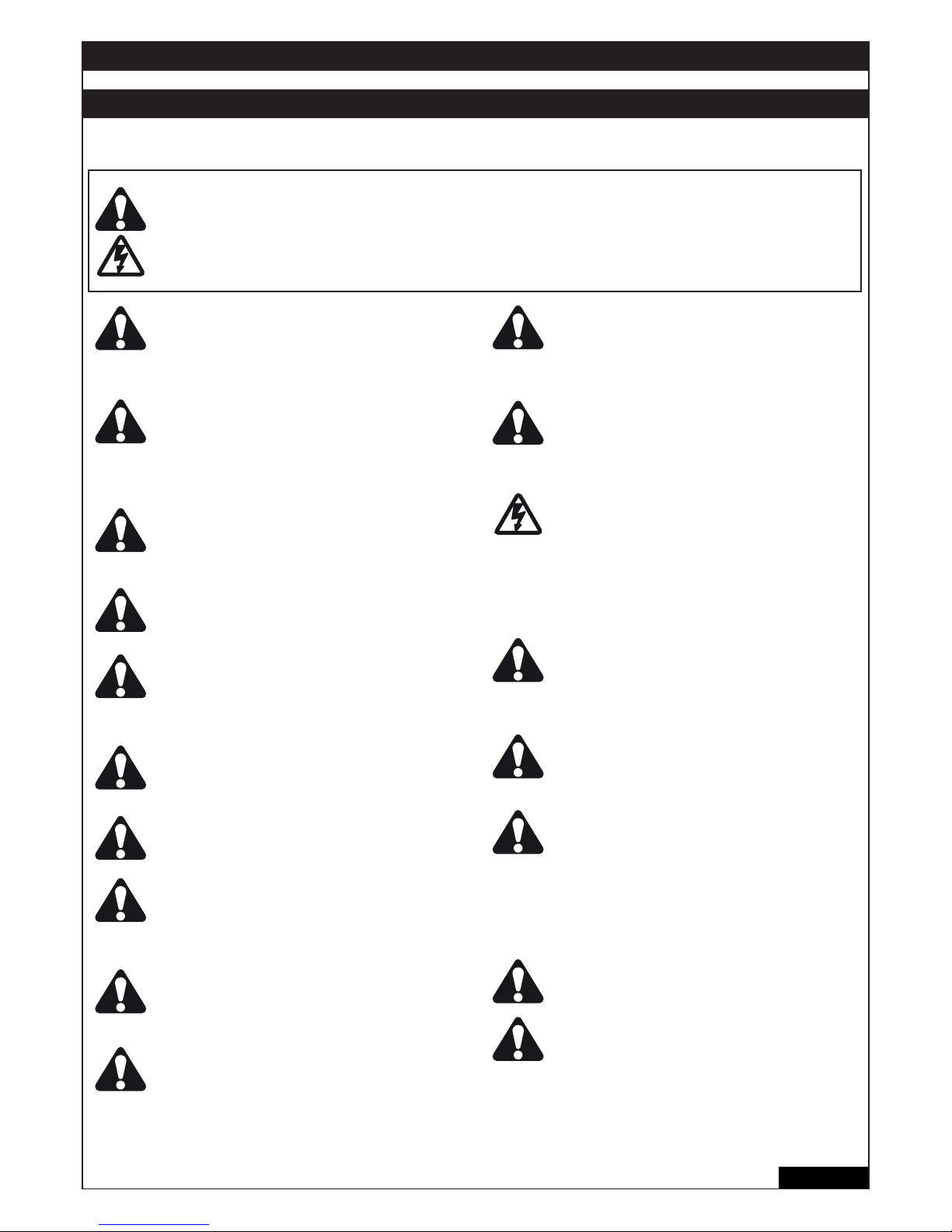
1/16 fr
AVERTISSEMENT / ATTENTION
INSTRUCTIONS IMPORTANTES POUR LE MONTAGE ET L‘UTILISATION
VEUILLEZ TOUT D‘ABORD LIRE CES REGLES DE SECURITE IMPORTANTES
Ces pictogrammes appellent à la prudence et ont valeur d‘avertissement, car leur non-respect peut entraîner un
risque de blessures corporelles ou de dommages matériels.
Veuillez lire attentivement ces avertissements. Cet ouvre-portail est conçu et testé de manière à offrir un service
raisonnablement sûr sous réserve d‘être installé et utilisé strictement selon les règles de sécurité suivantes.
Le non-respect des règles de sécurité suivantes peut provoquer de sérieux dommages corporels ou matériels.
Une prudence particulière s‘impose lors de
l‘utilisation d‘outils et de petites pièces. Ne pas
porter de bagues, de montres ou de vêtements
amples lors des travaux de montage ou de
réparation d‘un portail.
Les câbles électriques doivent être posés
conformément aux prescriptions locales
relatives aux systèmes et installations
électriques. Le câble électrique doit uniquement
être raccordé à un réseau électrique
correctement relié à la terre.
Lors du montage, un confi nement entre la pièce
entraînée et les pièces environnantes du
bâtiment (par exemple une paroi) doit être
considéré en raison du mouvement d‘ouverture
de la pièce entraînée.
Déposer toutes les serrures montées sur le portail afi n d‘éviter d‘endommager ce dernier.
Après installation, il convient de vérifi er
l‘ajustement correct du mécanisme ainsi que le
bon fonctionnement de l‘entraînement, du
système de sécurité et du dispositif de
déverrouillage d‘urgence (le cas échéant).
Si le portail possède un portillon pour piétons,
l‘entraînement ne doit pas se déclencher ou
continuer à fonctionner si le portillon n‘est pas
fermé correctement.
Le portail ne doit pas empiéter sur une zone de
passage de public durant son fonctionnement.
Les portails légèrs doivent être considérablement renforcées afi n d‘éviter tout risque
d‘endommagement.
La meilleure solution consiste à s‘adresser au
fabricant de votre portail.
Actionnez la commande d’ouverture UNIQUEMENT quand le portail est complètement visible
et non obstrué. Interdisez aux enfants de jouer
près du portail.
L’humidité et l’eau détruisent le système de
commande. Assurez-vous que le capot ne soit
pas du tout exposé à l’eau ou à l’humidité.
Il est important que le portail reste toujours
parfaitement opérationnel. Tout portail qui
bloque ou reste coincé doit être immédiatement
réparé. Ne pas essayer de le réparer soi-même,
mais faire appel à un spécialiste.
Tenir tous les accessoires supplémentaires hors
de portée des enfants. Ne pas laisser les enfants
utiliser les boutons ou les télécommandes. La
fermeture d‘un portail peut provoquer de
sérieuses blessures.
Débranchez le courant de l’automatisme de
portail avant de commencer toute réparation ou
d’ôter un couvercle. Dans l’installation fi xe, il
convient de prévoir un sectionneur afi n de ga-
rantir une coupure sur tous les pôles au moyen
d’un interrupteur (avec une course minimale
d’ouverture des contacts de 3 mm) ou un fusible
séparé.
S‘assurer que les personnes qui assurent le
montage ou la maintenance ainsi que celles qui
utilisent l‘ouvre-portail respectent les présentes
instructions. Conserver ces instructions de
sorte à pouvoir les retrouver rapidement.
La protection absolue des zones de pincement
et de cisaillement doit être garantie une fois le
montage de l‘entraînement sur le portail
terminé.
Cette installation ne doit pas être utilisée par
des personnes (y compris les enfants) qui ne
disposent pas de toutes leurs facultés
physiques ou mentales, ou qui n’ont pas
suffi samment d’expérience en matière
d’utilisation de l’installation, dans la mesure où
elles ne sont pas surveillées ou n’ont pas été
formées à l’utilisation de l’installation par une
personne responsable de leur sécurité.
Surveiller les enfants afi n de s’assurer qu’ils ne
jouent pas avec l’installation.
Entraînement de portail automatique – Ne pas se
tenir dans la zone de le portail, car celle-ci peut
être actionné de manière impromptue.
Conservez cettes instructions!
Page 69

CARACTÉRISTIQUES TECHNIQUES DE LA COMMANDE
Tension : 230 VCA +/- 10% 50-60 Hz
Transformateur : 230/24 VCA, 150 VA
Sortie moteur : 24 VCC
Consommation max. : max. 400 W (en service)
Consommation de veille : max. 4 W (sans accessoires)
Alimentation accessoires : 24 VCC / 600 mA max.
Température de service : -20 ºC ÷ +55 ºC
Mode de fonctionnement : Standard, Automatique
Dimensions : 250 x 75 mm (sans boîtier)
Dimensions boîtier : env. 300 x 220 x 120 mm
Type de protection : IP45
Fusibles : 2 x 2A rapide
Télécommande : max. 170 x code alternant
Fréquences possibles : 433 MHz, 868 MHz
CONFIGURATION TYPIQUE D’UNE INSTALLATION :
1. Commande motorisée
2. Système de commande
3. Barrières photoélectriques (actives quand fermé), hauteur maxi
200 mm première barrière photoélectrique
4. Barrières photoélectriques (actives quand ouvert òu fermé),
hauteur maxi 200 mm deuxième barrière photoélectrique (option)
5. Lampe clignotante (option)
Elle représente un signal optique important pour le mouvement
du portail.
6. Interrupteur à clé ou serrure à code (option)(option)
Est appliqué côté extérieur. Le portail s’ouvre au moyen d’une
clé ou en entrant un code numérique.
7. Le profi lé de contact (option)
Bloque le portail en cas de contact Les profi lés de contact
peuvent être appliqués sur les piliers ou au portail. S’il est
nécessaire, les profi lés de contact doivent être appliqués
jusqu’à une hauteur de 2,5 m.
2/16 fr
POSE DU COFFRET DE COMMANDE
Le système de commande comprend plusieurs composants.
- coffret de commande 1
- couvercle de coffret 1
- système de commande 1
- transformateur 1
- plaque de fond (assemblé) 1
- collier de fi xation grande 1
- collier de fi xation petite 3
- clip de fi xation 6
- vis 3,5mm x 9,5mm 4
- grande rondelle 1
- grande vis 1
- oeillet de câble 1
- écrou M8 2
- rondelle M8 1
- grande vis defermeture 5
PREPARATIFS DU COFFRET DE COMMANDE
Ouvrir les 4 trous au fond du coffret à l’aide d’un
tournevis ou d’un outil similaire. Fixer le grand
passage de câble à gauche, les autres comme dans
l’illustration. L’humidité et l’eau détruisent le système
de commande. Tous les orifi ces et les passages de
câbles doivent être étanches à l’eau. Le coffret de
commande avec la commande motorisée doit être
monté avec les passages de câbles vers le bas
4
+
Page 70
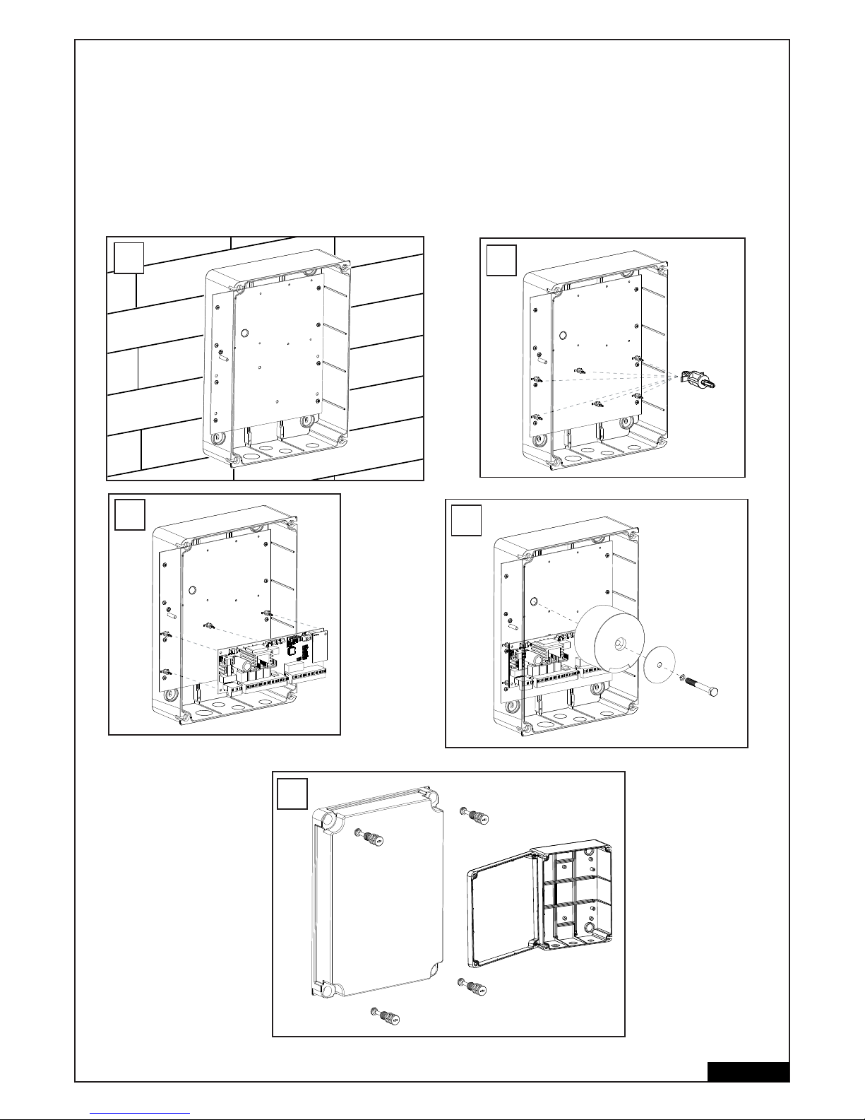
PROCEDE RECOMMANDE
Vissez la partie inférieure du coffret au mur mesurez auparavant les écarts requis et déterminez les trous adaptés (les fi xations ne sont pas
compris) Die Montageplatte ist bereits im Gehäuse montiert. (A)
Appuyez les clips de fi xation sur les trous prevues. (B)
Pesez la commande sur les clips de fi xation. (C)
Visser le transformateur par la grande vis et la grande rondelle sur la plaque de montage. (D)
Placez les 4 grandes vis de fermeture du coffret dans le couvercle du coffret. Vissez 2 des vis de fermeture (à gauche ou à droite) d’env. 2 cm
dans le coffret. Ensuite, le couvercle peut se rabattre sur le côté. (E)
Fermez le coffret en essayant de visser complètement les vis. Si le couvercle ne ferme pas correctement, le coffret ne sera pas bien à plat sur le
mur et il en sera déformé. Ceci doit être corrigé. 1Il est très important que plus tard le coffret puisse fermer en étant étanche à l’eau.
3/16 fr
6x
B
C
D
A
E
Page 71
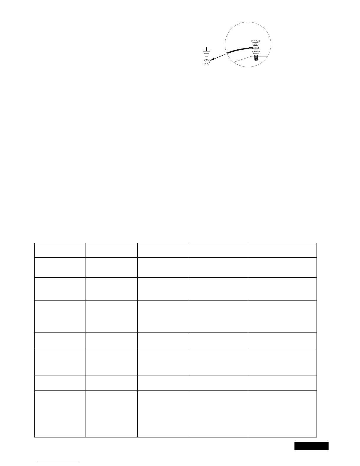
CÂBLAGE DU SYSTÈME DE COMMANDE/ APERÇU :
a. Commencez avec le câble d’alimentation 230 V encore
hors tension du côté gauche du coffret.
b. Fixer l’oillet de câble au conducteur de terre (comme indiqué) .
Raccordez tous les autres câbles au système de commande.
CABLES ET CABLAGE
L’utilisation de câbles blindés du moteur à la commande est recommandée.
Les infl uences magnétiques et inductives ne peuvent pas provoquer de bourdonnements ou nuire au bon fonctionnement de la porte.
Evitez de manière générale :
- d’installer la commande trop loin de la porte.
- de poser ensemble les câbles 230 V et basse tension. Interdit selon les réglementations relatives aux installations électriques.
- de poser les câbles pour les barrières photoélectriques, les interrupteurs, la lampe clignotante et la serrure électrique avec le câble
d’alimentation du moteur.
- de poser les câbles de télécommunication ou pour l’éclairage du jardin avec le câble d’alimentation du moteur.
- les câbles en cuivre rigides sont diffi ciles à poser, surtout lorsque les sections de câbles sont plus importantes. Utilisez des câbles souples.
- utilisez des câbles adaptés à la pose à l’extérieur et en terre, ou passez-les dans des gaines adaptées, ou renseignez-vous auprès
de votre électricien.
Nous recommandons les accessoires suivants :
- Kit LA400-JB40E pour la prolongation des câbles d’une installation. Composé de 12 m de câble, 6 pôles, de couleurs identiques àcelles de
l’entraînement, boîtier de distribution IP65, passe-câbles à vis et matériels de fi xation.
- 041ASWG-0482-50 bobine de 50 m, câble de connexion, 6 pôles pour l’extérieur. Pose possible sans gaine. Couleurs identiques à celles de
l’entraînement.
Dimensions des câbles :
Les dimensions fi gurant dans le tableau sont des valeurs minimales. Des sections plus importantes sont toujours possibles.
- alimentation électrique 230V pour la commande : min. 0,75 mm² 3 pôles
- alimentation électrique 230V pour le transformateur, installé séparément (par ex. Dans le garage) et tension inférieure ou égale à
42V vers la porte. Voir tableau.
- câblage du moteur : 2 câbles min. 1,0 mm², 4 câbles min. 0,75 mm² (ou câbles blindés)
- serrure électrique : voir tableau.
- interrupteurs, barrières photoélectriques, lampe clignotante : voir tableau etc. min.0,5 mm²
4/16 fr
Modèle d’entraînement
LYN, SCS, ART
Câblage du moteur
SUB (entr. encastrable)
Câblage du moteur
Transformateur installé
séparément (dans le
garage) et alimentation
basse tension de la
commande
Serrure électrique (12 V)
Câblage
Antenne externe (retirez
l’antenne d’origine de la
commande)
Interrupteur, lampe
clignotante, etc.
Barrière photoélectrique
Distance
0m - 6m
2 x 1,0mm²
4 x 0,75mm²
2 x 1,0mm²
3 x 0,75mm²
0,75mm²
0,75mm²
Câble coaxial
50 Ohm
0,5mm²
0,5mm²
Distance
6m - 10m
2 x 1,0mm²
4 x 0,75mm²
2 x 1,0mm²
3 x 0,75mm²
0,75mm²
0,75mm²
Câble coaxial
50 Ohm
0,5mm²
0,5mm²
Distance
10m - 12m
Normal
Wiring
Utiliser des câbles
blindés pour les ‚ câbles
de moteur plus petits
1,0mm²
1,0mm²
Câble coaxial
50 Ohm
0,75mm²
0,75mm²
Distance
12m – xx
Max. 15m
Utiliser des câbles blindés pour
les ‚ câbles de moteur plus petits
Utiliser des câbles blindés pour
les ‚ câbles de moteur plus petits
Max. 30m; Min. 1,5mm²
Poids de la porte, 50 % maximum de la puissance du moteur
Max. 30m; Min. 1,5mm²
Câble coaxial
50 Ohm
(max. 25m)
Min. 0,75mm²
Max. 30m
Min. 0,75mm²
Max. 20m
Page 72
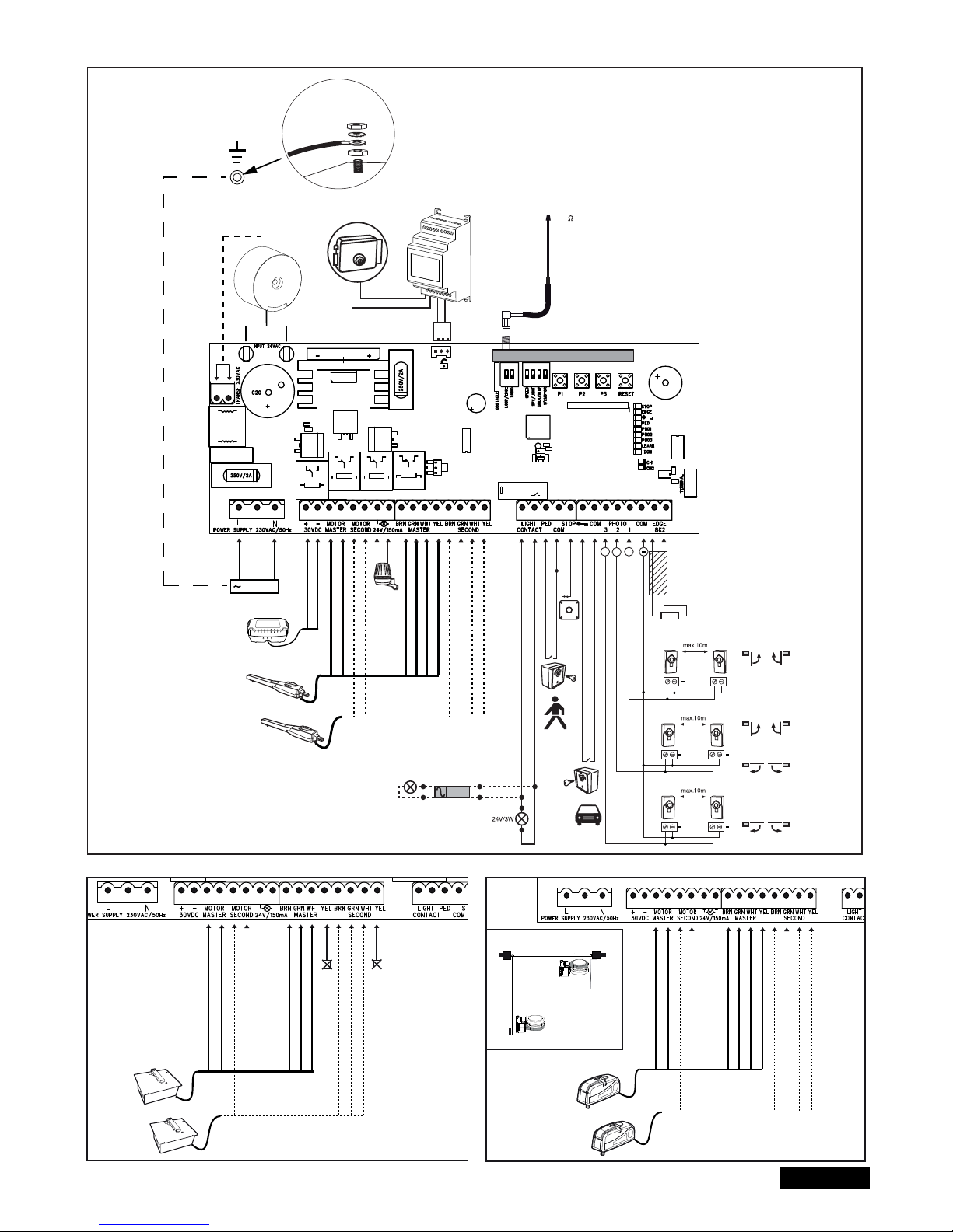
5/16 fr
SCHEMA DES CONNEXIONS
LYN/SCS
230VAC
PE
PE
Model
203285
Ω
8.2
+
+
+
+
+
+
+
Relay
+++
+
-
RED
RED
BLUE
BLUE
Model
CM475
BROWN
GREEN
WHITE
BROWN
GREEN
WHITE
YELLOW
YELLOW
RADIO MODULE
Model
207399
230 VAC
50
RED
RED
BLUE
BLUE
BROWN
GREEN
WHITE
BROWN
GREEN
WHITE
not required
not required
RED
RED
BLUE
BLUE
BROWN
GREEN
WHITE
BROWN
GREEN
WHITE
YELLOW
YELLOW
ART
SUB
Closed position
Open position
batterie
externe
Page 73
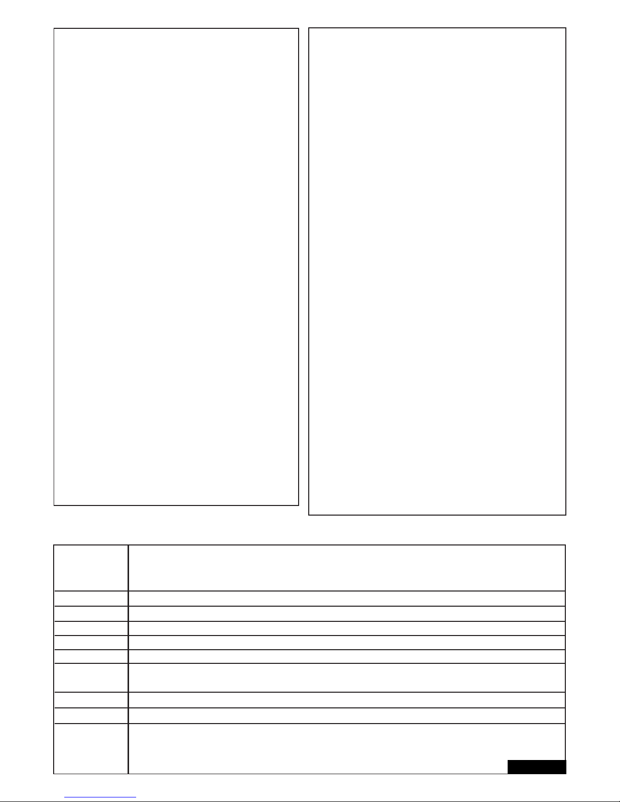
FONCTIONS DES BOUTONS-POUSSOIRS P1, P2, P3 & RESET
P1+P2+P3
P1
P1 + P2
P2 + P3
P1 + P3
P2
P3
DIP „RADIO“ + P1
DIP „RADIO“ + P2
RESET
Mode individuel : les vantaux peuvent être déplacés individuellement. Activer la fonction : Appuyer simultanément sur
P1+P2+P3. La DEL LEARN clignote tant que la fonction est activée. La touche P1 déplace le moteur 1. La touche P2 déplace le
moteur 2. Désactiver la fonction : Attendre 20 secondes ou débrancher la commande. Si les vantaux ferment d’abord, inversez
les câbles rouge et bleu.
Programme automatiquement les postions de fi n de course.
Programme automatiq. les postions de fi n de course (ainsi que des positions supplémentaires, par ex. Soft-Start et Soft-Stop).
Temporisation de la serrure électrique
Réglage de la temporisation de vantail
Fermeture automatique. Pour confi rmer, appuyez sur la touche P2.
Réinitialisation logicielle aux paramètres d’usine. Appuyez pendant 10 secondes sur la touche. La réinitialisation n‘agit pas sur
la mémoire radio (voir Radio).
Programmation des télécommandes pour le canal 1. Signal pour les deux entraînements (vantaux)
Programmation des télécommandes pour le canal 2. Signal pour un entraînement (moteur 1)
Programmation de l‘interface Internet ou de la surveillance de portail : Remarque : Sur cette commande, la touche RESET
n‘entraîne pas de réinitialisation aux paramètres d‘usine. Elle sert uniquement à la programmation de l‘interface Internet ou
de la surveillance du portail. Voir description de la touche P3 pour une réinitialisation aux paramètres d‘usine.
Bouton Fonction
6/16 fr
DESCRIPTION DES BORNES
DESCRIPTION FONCTION
L Raccordement L 230 Volt câble d’alimentation
N Raccordement N 230 Volt câbled’alimentation
30VDC raccordement d’un kit de batterie externe
Motor MASTER Motor 1 (Master, ouvre en premier)
Motor MASTER Motor 2 (Second, ouvre en second)
Pour vérifi er la polarité correcte, voir les sections « Réglage de base
» et « Fonctions des boutons-poussoirs P1, P2, P3 & RESET »
24 V /150 mA lampe clignotante (accessoires)
MASTER Motor1
BRN câble brun
GRN câble vert
WHT câble blanc
YEL câble jaune
SECOND Motor2
BRN câble brun
GRN câble vert
WHT câble blanc
YEL câble jaune
Light Contact Surveillance de porte/éclairage du jardin
PED Connecteur pour l’arrêt d’urgence ou...
COM Pôle négatif
STOP ..coupure stop
“symbole de clé“ interrupteur à clé
COM Pôle négatif
PHOTO 3 barrière photoélectrique 3 (ouvrir)
PHOTO 2 barrière photoélectrique 2 (ferm. + ouv.)
PHOTO 1 barrière photoélectrique 1 (fermer)
COM Pôle négatif
EDGE Le profi lé de contact de 8,2 kOhm
8,2 kOhm
“symbole” Serrure E Entrée Serrure électrique
« entrée de système de commande »
INPUT 24 VAC 24 Volt tension d’entrée du transformateur. Peut
être raccordée avec une quelconque polarité
Transformateur 230 VAC 230 Volt câble d’alimentation vers
transformateur. Peut être raccordé avec une
quelconque polarité.
250 V/2 A fusible 250 V/2 A (2x rapide)
DESCRIPTION DES DEL (DIODES LUMINEUSES)
Description Couleur Fonction
STOP Vert Arrêt d’urgence
ALLUME : Arrêt d’urgence actif
ETEINT : OK (cavalier, si aucun interrupteur
n’est connecté)
EDGE Vert Le profi lé de contact 8.2 kOhm
ALLUME : Activé
ETEINT : OK (cavalier d’une résistance de
8,2 kOhm si aucune profi lé de contact n‘est
connecté)
« symbole de clé“ Rouge interrupteur à clé
ALLUME : interrupteur actionné
ETEINT : interrupteur non actionné
PED Rouge Interrupteur à clé pour 1 vantail
ALLUME : Interrupteur actionné
ETEINT : Interrupteur non actionné
PHO1 Rouge barrière photoélectrique 1 (fermer)
ALLUME : OK (active)
ETEINT : aucune barrière photoélectrique
raccordée
PHO2 Rouge barrière photoélectrique 2 (ferm. + ouv.)
ALLUME : OK (active)
ETEINT : aucune barrière photoélectrique
raccordée
PHO3 Rouge barrière photoélectrique 3 (ouvrir)
ALLUME : OK (active)
ETEINT : aucune barrière photoélectrique
raccordée
LEARN Jaune programme d’apprentissage Statut
ALLUME : Programme d’appr. actif
ETEINT : pas de programme d’appr.
DGN Rouge programme de diagnostique (voir page 15)
CH1 Rouge Programmation des télécommandes pour
le mode à 2 vantaux
ALLUME : Une nouvelle télécommande
peut être programmée
ETEINT : Fonction désactivée
CH2 Rouge Programmation des télécommandes pour
le mode à 1 vantail (voir CH1)
Page 74

7/16 fr
ACCESSOIRES (voir aussi la schema des connexions)
TÈLÈCOMMANDES RADIO (EN OPTION) MODÈLES: TX2EV, TX4EV, TX4UNI (télécommandes),
747EV (serrure à code radio) , 128EV (interrupteur mural à radio 2 fonctions)
LAMPE CLIGNOTANTE (EN OPTION) MODÈLE: FLA24-2, FLA1-LED
Une lampe clignotante peut être raccordée au système de commande (Bornes: 24 VDC / 150 mA). Elle avertit les personnes qui se trouvent
devant le portail en mouvement. La lampe clignotante devrait être placée si possible en hauteur pour être bien visible. Le système de
commande émet un signal constant qui est transformé par la lampe en un clignotement.
INTERRUPTEUR A CLE (EN OPTION) MODÈLE : 100010, 100027, 100034, 100041
L’installation peut être commandée avec un commutateur à clé. (bornes : symbole de clé et COM)
Voir également la description fi gurant sous Commutateurs DIP OPEN/PED.
INTERRUPTEUR D’ARRET D’URGENCE / D’ARRET (EN OPTION) MODÈLE : 600084
Cette sortie sert au raccordement d’un interrupteur d’arrêt d’urgence qui immobilise le portail dans les deux sens.
LE PROFILÉ DE CONTACT (EN OPTION) MODÈLE : 600046, 60003, 600077, 600060
(le commutateur DIP „LOOP/EDGE“ doit être éteint)
Il est mpossible de connecter au système de commande un profi lé de contact (bornes: STOP / 8,2 kOhm) fonctionnant selon le principe 8,2 K
Ohm, à savoir une résistance d’essai de 8,2 K Ohm est fi xée à l’extrémité du profi lé de contact. Elle garantit le contrôle permanent du circuit
électrique. Le système de commande est livré équipé d’une résistance incorporée de 8,2 K Ohm. Plusieures profi lés de contacts sont raccordés
en série.
BARRIÈRES PHOTOÉLECTRIQUES ( EN OPTION) MODELLE 771E, 772E:
Nous recommandons la mise en place d‘une barrière photoélectrique. Utilisez le modèle 771E ou 772E, qui fait également partir du kit d‘accessoires
de sécurité APLUS-EV.
SAFETY ACCESSORY KIT (EN OPTION): APLUS-EV
La commande est déjà équipée d‘une antenne standard. Pour de plus grandes portées, l‘antenne externe comprise dans le kit d‘accessoires APLUS-
EV (ce kit comprend la barrière photoélectrique 771E, le feu clignotant FLA1-LED et l‘antenne externe SWG-ANT-EV) peut être branchée comme
indiqué dans le synoptique de raccordement.
myQ (EN OPTION)
(uniquement avec interface Internet 828EV) :
Permet la commande du portail via l‘Internet ou un Smartphone.
SURVEILLANCE DE PORTAIL (EN OPTION) :
(uniquement avec surveillance de portail 829EV) :
Permet la surveillance visuelle et sonore de la position du portail. Le portail peut aussi être fermé au moyen de cet appareil.
BATTERIE EXTERNE (EN OPTION)
Les connecteurs servent à charger une batterie externe.
En cas de panne de secteur, la batterie assure l’alimentation électrique de l’entraînement. Une batterie entièrement chargée pour fournir
l’énergie nécessaire à plus de 24 heures. Les batteries sont soumises au vieillissement et leur capacité diminue au fi l du temps. Remplacez la
batterie tous les 2-3 ans, en fonction de son utilisation.
SERRURE ELECTRIQUE ( EN OPTION)
Le système de commande est en mesure de faire fonctionner une serrure électrique 12 V. (le mode d’emploi est joint à la serrure électrique).
Pour cela, il faut raccorder au système de commande principal un système de commande auxiliaire destiné à la serrure électrique.
Si la serrure électrique n’ouvre pas en raison d’une pression excessive de la porte, une fonction spéciale peut être programmée : appuyez
pendant env. 5 secondes simultanément sur les touches P2 et P3 et comptez les clics audibles.
1 clic = alimentation électrique de la serrure électrique pendant env. 4 secondes (paramètre d’usine)
2 clics = la porte ferme pendant une seconde puis s’ouvre. De plus, après avoir atteint la position fermée du portail, appuyer brièvement sur
l’actionnement pour favoriser le verrouillage de la serrure électronique. Avis : Pour ce faire, le portail doit être équipé de butées au sol.
SURVEILLANCE DE PORTE OU ECLAIRAGE ( ENOPTION)
Les connexions disposent de deux fonctions, selon l‘ commutateur DIP Light/Spy est allumé ou non. Voir également sous « commutateurs DIP» dans
la présente notice. La sortie ne dispose pas d’alimentation en courant électrique et ne peut être chargée que jusqu’à 24V.
Surveillance de portail / état du portail (Spy)
Une DEL, une ampoule (24V / 3W max.) ou un relais peuvent être raccordés aux bornes pour affi cher l’état du portail.
DEL éteinte = portail fermé
DEL clignote lentement = ouverture du portail
DEL allumée = portail ouvert
DEL clignote rapidement = fermeture du portail
Eclairage de cour / éclairage de 120 secondes
Une lampe (24V / 3W max.) ou un relais peuvent être branchés aux bornes.
Lorsque la commande reçoit un signal pour l’ouverture ou la fermeture, la lampe s’allume pendant 120 secondes, puis s’éteint automatiquement.
ATTENTION: La sortie supportant une charge seulement jusqu‘à 24V maximum, ou un relais doit être intercalé.
Page 75

8/16 fr
BARRIERES PHOTOELECTRIQUES (OPTION) 771E, 772E
Les barrières photoélectriques servent à protéger le portail et doivent être utilisées.
L’emplacement de la pose est fonction du modèle de portail. Selon la norme EN12453,
une paire de barrières photoélectriques doit être posée à l’extérieur à une hauteur de
200 mm activée en position « fermeture ». Les barrières photoélectriques comprennent
un émetteur et un récepteur et doivent se faire face l’une et l’autre. La barrière photo- électrique est fi xée au mur au moyen de petites vis et de chevilles. Si la fonction «
fermeture automatique » est possible, il faut alors installer la barrière photoélectrique
Chamberlain – Failsafe. Le système Chamberlain – Failsafe (système à 2 câbles) possède des deux côtés une petite DEL visible de l’extérieur (lumière) pour affi cher le statut
de la barrière photoélectrique.
Programmation de la barrière photoélectrique :
- raccorder barrières photoélectriques correctement
- effectuer une programmation de la course des vantaux de porte.
Suppression d’une barrière photoélectrique de la commande :
une barrière photoélectrique connectée ne peut pas être supprimée sans que la
commande ne bloque le fonctionnement au niveau de la connexion correspondante.
Pour supprimer une barrière photoélectrique du programme de la commande :
- retirer la barrière photoélectrique
- couper brièvement l’alimentation électrique
- effectuer une programmation de la course des vantaux de porte.
Diagnostic à la barrière photoélectrique Chamberlain-Failsafe
DEL constante = OK
DEL clignote = barrière photoélectrique bloque le système de commande
DEL éteinte = hors circuit, mauvais raccordement ou permutation des pôles
Diagnostic au système de commande
DEL éteinte = OK aucune barrière photoélectrique raccordée
DEL clignote = système de commande bloqué
Connecteur 1 & COM
Actif lorsque la porte se ferme (inverse le mouvement de la porte)
Connecteur 2 & COM
Actif lorsque la porte se ferme et s’ouvre
Connecteur 3 & COM
Actif lorsque la porte s’ouvre
(la porte s‘immobilise jusqu‘à ce que l‘obstacle soit écarté du rayon infrarouge,
avant de poursuivre son mouvement)
RADIOCOMMANDE
PROGRAMMER / EFFACER LES TÉLÉCOMMANDES
Le récepteur a 2 canaux CH1 et CH2. L’utilisation d’un ou 2 canaux
permet la mise en marche d’un battant ou des 2 battants du portail. Par
exemple : si CH2 ou P2 reçoit le signal de la télécommande, alors un
seul battant s’ouvrira. Si vous appuyez sur une touche quelconque de la
télécommande avec CH1 ou P1, alors vous ouvrirez les 2 battants du
portail.
PROGRAMMATION
1: Allumez le commutateur DIP „RADIO“.
2: Appuyer brièvement sur le bouton P1 pour CH1 ou sur P2 pour CH2
pour allumer la led de signalisation respective.
3: Appuyer sur le bouton de la télécommande que vous voulez program mer jusqu´à ce que la led de signalisation s’éteigne. Répéter la procé dure pour toutes les télécommandes (85 télécommandes peuvent être
programmées par canal).
Important : Déclenchez le commutateur DIP „RADIO“ toujours après l‘usage. Assurez-vous que le même bouton de la télécommande ne soit pas
programmé sur CH1 et CH2. Cela empêcherait le bon fonctionnement de
l’installation.
EFFACER
- Allumez le commutateur DIP „RADIO“.
- Appuyer sur le bouton P1 usqu´à ce que la led de signalisation au bout
de 10 secondes s’éteigne.
Pour confi rmer, les deux DEL CH1 et CH2 clignotent 8 fois.
- Déclenchez le commutateur DIP „RADIO“
RADIO MODUL
E
ON ON
RADIO MODUL
E
ON ON
RA
ON ON
RA
ON ON
+
+
+
+
+
+
+
+++
Page 76

9/16 fr
PROGRAMMATION DE L‘INTERFACE INTERNET myQ
A l‘aide de la touche RESET de la commande
1. Brancher l‘interface Internet Liftmaster et son routeur au câble réseau.
2. Alimenter électriquement l‘interface Internet Liftmaster.
3. Créer un compte en ligne à l‘aide de l‘application Liftmaster myQ pour
Smartphone la plus récente ou sur www.liftmaster.eu.
4. Enregistrer l‘interface Internet Liftmaster.
5. Cliquer sur « Ajouter un nouvel appareil » et suivre les étapes décrites dans
l‘application ou sur le site Internet.
6. Remarque : Si vous appuyez sur la touche RESET, vous entendrez un signal
sonore et les DEL CH1 et CH2 s‘allument. Puis, après la synchronisation,
elles clignotent trois fois et s‘éteignent.
7. L‘application indique si la programmation a réussi et vous invitera à attribuer
un nom au portail.
PROGRAMMATION DE LA SURVEILLANCE DE PORTAIL
A l‘aide de la touche RESET de la commande
1. Alimenter électriquement la surveillance de portail et la positionner de telle
sorte dans la maison qu‘elle soit bien visible. Si le lieu d‘installation est trop
loin du portail, la connexion peut être faible ou souvent interrompue. Choisis sez un endroit plus approprié pour l‘installer.
2. Appuyez brièvement sur la touche « LEARN » au dos de la surveillance de
portail. Les DEL rouge et verte clignotent en alternant. Dans un délai de 60
secondes, appuyer brièvement sur la touche RESET de la commande. Les
DEL rouge et verte s‘allument brièvement pour confi rmer la programmation.
Supprimer la surveillance de portail
appuyer pendant au moins 10 secondes sur la touche « LEARN » au dos de la
surveillance de portail.
Un bref signal sonore confi rme le succès de la suppression.
ADIO MODULE
ADIO MODULE
Page 77

DETECTEURS DE BOUCLES
(le commutateur DIP LOOP/EDGE doit être allumé)
Les détecteurs de boucles réagissent au métal et sont souvent
utilisés pour la détection de voitures et de poids-lourds, mais ne
réagissent pas aux motos et aux piétons.
Boucle de sortie A
La boucle de sortie se trouve derrière la porte et ouvre la porte
lorsqu’elle est fermée, la maintient ouverte ou l’ouvre une nouvelle
fois. Les commutateurs DIP OPEN/STEP et LOOP/EDGE doivent être
allumé. Les barrières photoélectriques doivent être connectées et la
fonction „Fermeture automatique“ doit être activée.
Détecteur de boucle de sécurité et détecteur de
boucle dans la zone de pivotement de la porte B,C
Les détecteurs de boucles servent à la détection des véhicules
(voitures et poids-lourds ; en tant que mesure de sécurité unique,
ils ne sont pas admissibles puisqu’ils ne détectent pas les
personnes). Le module d’analyse des détecteurs de boucles est
raccordé en tant que transmetteur de signaux aux bornes de la
baguette de contact 8.2kOhm. Si vous souhaitez aussi utiliser des
baguettes de contact :
vérifi ez avant l’installation quel est le mode de fonctionnement
adapté à votre installation.
Détecteur de boucle de sécurité
=> Le commutateur DIP OPEN/STEP doit être allumé.
Détecteur de boucle dans le zone de pivotement de la porte
=> Déclancher le commutateur DIP OPEN/STEP
Vous pouvez vous renseigner auprès de notre service sur d’autres
options concernant les déteteurs de boucles.
10/16 fr
RN WHT YEL
ASTER
BRN GRN WHT YEL
SECOND
COM
PHOTO
3 2 1
C
LIGHT
CONTACT
PED
COM
STOP
NO
Model
203292
Model
203292
RN WHT YEL
ASTER
BRN GRN WHT YEL
SECOND
COM
PHOTO
3 2 1
COM EDGE
8.2KΩ
LIGHT
CONTACT
PED
COM
STOP
NO
COM
NC
A
B
C
A
B C
RADIO
ON ON
RADIO
MOD
ON
RADIO
MOD
ON
Page 78

Commutateurs DIP
MOTEUR 1/2
Sélectionne si 1 ou 2 moteurs sont raccordés à la commande.
ETEINT : 2 moteurs sont connectés
ALLUME : 1 moteur est connecté
OPEN/STEP
Modifi e la programmation et la réaction de la commande aux signaux.
Pour l’utilisation des détecteurs de boucles, veuillez vous reporter
d’abord à la section « Détecteurs de boucles ».
Mode pas-à-pas : Le premier signal ouvre la porte, le second
l’immobilise, le troisième signal la ferme, le quatrième l’immobilise, le
cinquième l’ouvre, etc.
Mode d’ouverture : la porte ne réagit pas aux signaux de commande
tant qu’il s’ouvre et n’a pas atteint la position OUVERTE.
ETEINT : Mode pas-à-pas
ALLUME : Mode d’ouverture
LIGHT/SPY
N’enfi cher que si la fonction est nécessaire, sinon laisser libre.
ETEINT : LIGHT
ALLUME : SPY
OBSTACLE
Equipé en usine d’un pontage à fi l fi xe. Le sectionnement augmente la
puissance de travail à la commande. ATTENTION: Si le pontage à fi l
est sectionné, le portail doit être sécurisé avec des installations de
sécurité supplémentaires (réglette de contact, etc.).
LOOP/EDGE
Sélectionnez la fonction souhaitée
ETEINT : Baguette de contact
ALLUME : Détecteur de boucle
SPEED
Sélectionnez le type de moteur que vous souhaitez utiliser.
ETEINT : ART
ALLUME : LYN, SCS, ART, SUB
RADIO
Le commutateur DIP « RADIO » est nécessaire pour la programmation
des télécommandes. Le processus de programmation fi gure dans la
section correspondante de la présente notice.
ETEINT : Aucune programmation n’est possible
ALLUME : La programmation est possible
IMPORTANT : Toujours déclencher le commutateur DIP « RADIO »
lorsqu’il n’est pas utilisé.
TEMPORISATION DE VANTAIL
La temporisation de vantail est nécessaire pour l’ouverture et la
fermeture correcte des vantaux. Une temporisation de vantail plus
longue peut être nécessaire lorsque les conditions d’installation ou les
longueurs de vantail sont différentes.
Appuyez et maintenez les touches P1 et P3 simultanément pendant
env. 5 secondes et comptez le nombre de clics audibles. Les clics sont
générés par un relais (relais de lumière).
1 clic = temporisation courte d’env. 4÷8 secondes (paramétrage d’usine)
2 clics = temporisation moyenne d’env. 8÷12 secondes
3 clics = temporisation longue d’env. 12÷16 secondes
4 clics = temporisation intégrale ; le vantail 1 ne ferme que lorsque
le vantail 2 est entièrement fermé.
La temporisation à l’ouverture est toujours d‘env. 3÷5.
5 clics = aucune temporisation ;
les deux vantaux ouvrent et ferment simultanément
REMARQUE : la programmation (modifi cation) de la course réinitialise
la temporisation de vantail au paramétrage d’usine.
11/16 fr
RADIO MODULE
RADIO MODULE
ON ON
Page 79

12/16 fr
PREMIERE MISE EN SERVICE/ REGLAGE DE BASE
Procédez exactement point par point. En cas de doute, recommencez depuis le début. Prenez votre temps pour effectuer ces
réglages.
1. Est-ce que tous les éléments sont raccordés pour que le fonctionnement se fasse correctement ? Moteurs, barrières photoélectriques, profi lé de
contact de sécurité, interrupteur d’arrêt.
2. Assurez-vous que personne ne séjourne au niveau du portail ou puisse y séjourner.
3. Fermez le portail et accrochez-y les moteurs. Fixez les moteurs avec le boulon à goupille et tournez le levier de déverrouillage en direction du
pilier du portail. Les commandes motorisées sont verrouillées.
ART :
- pour le succès de la programmation de la course, les points de
référence doivent être réglés. A cet effet, les cames sous le carter de
l’ART doivent être réglées correctement. La came supérieure doit
déclencher le microrupteur en premier, puis la came inférieure. Les
microrupteurs ne doivent pas se déclencher simultanément ou lorsque
la porte a atteint ses positions de fi ns de course. Ecartez les cames au
moyen d’une pince ou d’un grand tournevis plat.
- déverrouillez la porte pour ces réglages.
- contrôlez ou corrigez les positions des cames de commutation comme
indiqué dans la notice pour les commandes porte OUVERTE et porte
FERMEE.
- réglage des commutateurs DIP en cas d’utilisation de l’ART :
Déclencher le commutateur DIP « SPEED ».
L’ART ne fonctionnera pas si le commutateur DIP « SPEED » set allumé.
SUB (entraînement encastrable) :
- Réglage des commutateurs DIP : le commutateur DIP « SPEED » est allumé pour un mouvement plus rapide de la porte. Il ne l’est pas si la porte
est très lourde ou que le fonctionnement doit être très sûr. Peut être modifi é à tout moment après l’installation.
Entraînements LYN / SCS :
Réglage des commutateurs DIP : le commutateur DIP « SPEED » est allumé pour un mouvement plus rapide de la porte. Il ne l’est pas si la porte
est très lourde ou que le fonctionnement doit être très sûr. Peut être modifi é à tout moment après l’installation.
Raccordez maintenant le système de commande au secteur.
REGLAGE DE BASE :
1. Appuyez simultanément sur les boutons P1, P2 et P3 durant 2 à 3 secondes jusqu’à ce que la DEL jaune clignote.
2. Observez en même temps le portail. Appuyez sur la touche P1 et maintenez-la appuyée durant 1 à 2 secondes. Le portail avec Moteur 1
doit se déplacer en direction AUF (OUVERT). (ne pas ouvrir complètement le portail, procéder par petits déplacements)
Si le moteur 1 ferme le portail au lieu de l’ouvrir, il est mal raccordé et il faut permuter les câbles rouge et bleu au moteur
(Attention : mettre auparavant le système de commande hors circuit !).
Remarque : Fonction générale – si vous relâchez le bouton, le portail s’arrête immédiatement. En appuyant une nouvelle fois, il se
déplace dans le sens inverse jusqu’à ce que vous relâchiez à nouveau le bouton, etc.
3. Appuyez sur la touche P2 et maintenez-la appuyée durant 1 à 2 secondes. Le portail avec Moteur 2 doit se déplacer en direction
AUF (OUVERT). (ne pas ouvrir complètement le portail, procéder par petits déplacements) Si le moteur 2 ferme le portail au lieu
de l’ouvrir, il est mal raccordé et il faut permuter les câbles rouge et bleu au moteur (Attention : mettre auparavant le système de
commande hors circuit !).
Remarque : Le système de commande demeure 20 secondes dans ce programme de réglage manuel. Recommencez le cas
échéant depuis le début en appuyant simultanément sur les touches P1/P2/P3.
Vérifi ez :
1. Uniquement sur SCS : Lorsque le vantail s’ouvre, le « taquet » avant du moteur ne doit PAS toucher la porte (buter ou frotter contre elle).
Interrompre l’ouverture à plusieurs reprises pour contrôler ! En cas de contact, la cote A/B doit être contrôlé et éventuellement la ferrure de la
porte rehaussée pour obtenir un plus grand écart.
2. Ouvrir les deux vantaux complètement. Ne pas ouvrir de trop ! Si aucune butée OUVERT n’existe, marquez le point d’ouverture
maximale.
3. Uniquement sur SUB (entraînement encastrable) : Ajustez à présent les butées de fi n de course mécaniques dans le boîtier.
Patientez jusqu’à ce que la DEL LEARN s’éteigne d’elle-même (20 secondes après avoir appuyé sur la touche).
Closed position
Open position
portail fermé
portail ouvert
Page 80

13/16 fr
PROGRAMMATION DES PARCOURS SIMPLE I
Remarque : Les butées de fi n de course dans FERME et OUVERT doivent être existantes.
1. Les battants doivent être fermés.
2. Appuyez sur le bouton P1 tant que la battant / moteur 1 commence à s’ouvrir. (DEL « LEARN » clignote)
Le programme automatique commence (déplacement lent) :
Le battant 1 se déplace jusqu’au butoir AUF (OUVERT).
Le battant 2 se déplace jusqu’au butoir AUF (OUVERT).
Ensuite, le battant 2 se déplace jusqu’au butoir ZU (FERME) et ernsuite le battant 1 se déplace jusqu’au butoir ZU (FERME).
Quand la DEL « LEARN » s’éteint, la programmation est terminée.
Remarque : Si les battants se ferment au lieu de s’ouvrir, les moteurs sont mal raccordés. Permutez rouge et bleu.
PROGRAMMATION DES PARCOURS SIMPLE II
Remarque : S’il n’y a aucun butoir en direction AUF (OUVERT), le battant devrait s’arrêter à un angle d’ouverture d’env. 90°.)
1. Les battants doivent être fermés.
2. Appuyez sur le bouton P1 tant que la battant / moteur 1 commence à s’ouvrir.
3. Appuyez une fois sur la touche P1 « tief drücken » (appuyer à fond) lorsque le battant / moteur 1 a atteint la position Portail AUF
(OUVERT). Le battant 2 démarre.
4. Appuyez une fois sur la touche P1 « tief drücken » (appuyer à fond) lorsque le battant / moteur 2 a atteint la position Portail AUF
(OUVERT). Le battant 2 se referme ensuite automatiquement. Puis le battant 1 ferme automatiquement.
5. La commande motorisée « apprend » automatiquement la position Portail ZU (FERME).
Sur demande, vous pouvez aussi programmer un point individuel dans Portail ZU (FERME).
Appuyez sur la touche P1 « tief drücken » (appuyer à fond) puis à la position souhaitée Portail ZU (FERME) pour le battant
respectif. Quand la DEL « LEARN » s’éteint, la programmation est terminée.
PROGRAMMATION DU PARCOURS « ADVANCED » (INDIVIDUEL)
Remarque : Dans ce programme, la touche P1 doit être appuyée à neuf reprises.
Une position (temps) est enregistrée à chaque pression de touche. Cela rend possible d’enregistrer l’arrêt progressif (course lente) pour s’adapter
individuellement au portail ou à l’application. Des phases d’arrêt progressif longues ou courtes sont possibles.
1. Les battants doivent être fermés.
2. Appuyez durant environ 5 à 6 secondes simultanément sur P1 et P2 jusqu‘à ce que le battant 1 démarre (s‘ouvre). Relâchez les touches !
3. Réappuyez sur P1 ; l’arrêt progressif en direction AUF (OUVERT) pour le battant 1 commence à partir de cette position.
4. Réappuyez sur P1 ; butoir AUF (OUVERT) atteint. Le battant 2 démarre maintenant automatiquement.
5. Réappuyez sur P1 ; l’arrêt progressif en direction AUF (OUVERT) pour le battant 2 commence à partir de cette position.
6. Réappuyez sur P1 ; butoir AUF (OUVERT) atteint. Le battant 2 démarre maintenant automatiquement et se ferme.
7. Réappuyez sur P1 ; l’arrêt progressif en direction ZU (FERME) pour le portail 2 commence à partir de cette position.
8. Réappuyez sur P1 ; butoir en direction ZU (FERME) atteint. Le battant 1 démarre maintenant automatiquement.
9. Réappuyez sur P1 ; l’arrêt progressif en direction ZU (FERME) pour le battant 1 commence à partir de cette position.
10. Réappuyez sur P1 ; butoir ZU (FERME) atteint. -> terminé !
Remarque : Si un battant atteint un butoir et que la touche L1 n’est PAS appuyée, la commande motorisée se déplace sur la butée et « apprend »
cette position automatiquement.
Page 81
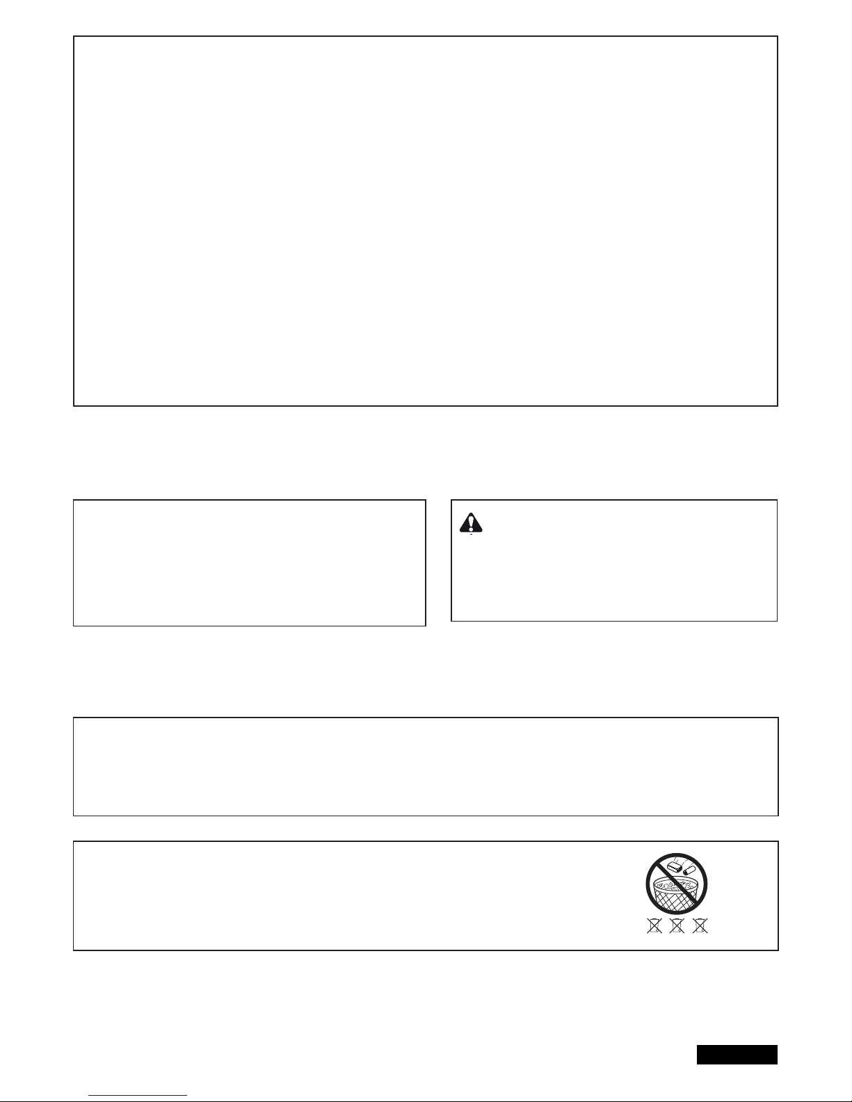
14/16 fr
FIN DE L’INSTALLATION / DE LA PROGRAMMATION:
Si le parcours est programmé, les émetteurs portatifs peuvent être également programmés (Cf. PROGRAMMATION / EFFACEMENT
DES EMETTEURS PORTATIFS).
1. Laissez maintenant le portail parcourir 2 cycles complets en appuyant sur l’émetteur manuel ou sur un bouton raccordé et observez
le déroulement. Refermez le portail SANS faire d‘autres réglages.
2. Si tous les réglages sont faits, vérifi ez la fonction des barrières photoélectriques, boutons, lampe clignotante, émetteur portatif,
accessoires, etc.
3. Montrez à toutes les personnes qui doivent être familiarisées avec le maniement du portail les différents mouvements du portail, les
fonctions de sécurité, le déverrouillage du portail et l’actionnement manuel.
Fermeture automatique du portail
Remarque : uniquement possible avec barrière photoélectrique raccordé et fonctionnant (1+COM). Il est possible de choisir un temps
de fermeture automatique situé entre 2 et 120 secondes.
Réglage
1. Appuyez sur P2 et maintenez appuyée jusqu’à ce que la DEL jaune commence à clignoter.
2. Lorsque la DEL jaune clignote, décomptez le temps d’ouverture qui doit être programmé.
3. A l’achèvement du temps souhaité, appuyez à nouveau sur P2. -> terminé !
Mise hors circuit
1. Appuyez sur P2 et maintenez appuyée jusqu’à ce que la DEL jaune commence à clignoter.
2. Appuyez sur P3. La DEL jaune s’éteint. -> terminé !
FORCE DE FONCTIONNEMENT DE LA COMMANDE
MOTORISEE
La force de fonctionnement de la commande motorisée se règle automa tiquement pendant la programmation du parcours. Une modifi cation (auto-
matique) n’est possible qu’avec une nouvelle programmation du parcours.
Si le portail se coince du fait des intempéries ou suite à des modifi cations
effectuées sur l’installation du portail (par ex. par la rouille ou un
graissage insuffi sant), il faut réparer le cas échéant.
Le système de commande satisfait les normes EN les plus
récentes. Une de ces normes prescrit que les forces de
fermeture au bord du portail ne doivent pas dépasser 400 N (40 kg)
dans les derniers 500 mm avant la fermeture du portail. Au-dessus
de 500 mm, la force maximale exercée au bord du portail peut
s’élever à 1400 N (140 kg). Si ceci ne peut être garanti, il faut
absolument appliquer un profi lé de contact évtl. jusqu’à une hauteur
de 2,5 m au portail ou au pilier opposé (EN12453).
ELIMINATION
L’emballage se compose de matières respectueuses de l’environnement. Il peut être éliminé dans les conteneurs de recyclage locaux.
Conformément à la directive européenne 2002/96/CE relative aux appareils électriques usagés, cet appareil doit être éliminé en fi n de cycle
de vie conformément aux réglementations, afi n d’assurer la revalorisation des matières utilisées.
Votre administration communale ou urbaine se fera un plaisir de vous renseigner au sujet des possibilités d’élimination.
ELIMINATION DES PILES
Les piles et piles rechargeables ne doivent pas être éliminées par les ordures.
Vous pouvez aussi remettre vos piles et piles rechargeables usagées gratuitement
à un commerçant ou un point de collecte communal à proximité de chez vous.
Les piles et piles rechargeables sont identifi és par une poubelle rayée
d’une croix, ainsi que par le symbole chimique du polluant, c‘est-à-dire
« Cd » pour Cadmium, « Hg » pour Mercure et« Pb » pour Plomb.
12VDC
Pb Cd Hg
Page 82

15/16 fr
INDICATION DE LA DEL DE DIAGNOSTIC
La DEL de diagnostic montre le premier dysfonctionnement survenu. Si d’autres dysfonctionnements sont actifs, ils ne sont éventuellement pas
indiqués.
Indication
1 clignotement
2 clignotements
3 clignotements
4 clignotements
5 clignotements
6 clignotements
7 clignotements
8 clignotements
9 clignotements
10 clignotements
11 clignotements
12 clignotements
13 clignotements
14 clignotements
15 clignotements
Descriptif
Commande motorisée 1 Défaut de contact d’un câble de
commande vers le système de commande
Comme 1 clignotement pour commande motorisée 2
Les points de fi n de course de la commande motorisée 2
ne sont pas acceptés.
A: Après ou durant le parcours d’apprentissage : la
commande motorisée 1 ne s’est pas ouverte
suffi samment
B: défaut de contact d’un câble de commande vers le
système de commande. Le câble jaune ou blanc n’a pas
de contact ou un mauvais contact.
Les points de fi n de course de la commande motorisée 1
ne sont pas acceptés.
Le parcours n’est pas programmé dans le système de
commande.
La force requise pour déplacer le battant est trop élevée.
A: Le portail est défectueux
B: Le portail est grippé
C: Le portail s’arrête quand le vent souffl e.
La barrière photoélectrique 1 bloque la fonction
A: Un objet bloque la barrière photoélectrique
B: L’orientation des lentilles l’une par rapport à l’autre est
imprécise.
C: L’alimentation électrique des barrières
photoélectriques est insuffi sante
La barrière photoélectrique 2 bloque la fonction
La barrière photoélectrique 3 bloque la fonction
L’interrupteur d’arrêt d’urgence bloque l’installation
Le Profi lé de contact bloque l’installation
A: Un objet s’appuie sur le profi lé de contact
B: Profi lé de contact défectueux
C: Alimentation électrique trop faible ou rupture du câble
d’alimentation.
Alimentation électrique du système de commande trop faible
A: Câble d’alimentation 230 V défectueux ou mauvais
contacts
B: Rupture du câble d’alimentation (câbles en cuivre
rigides)
C: La batterie fournie en accessoire pour se substituer
en cas de panne de courant est déchargée.
Défaut d’EEPROM
Echec du « démarrage » du système de commande
Uniquement sur LYN/SCS :
moteur encore déverrouillé
Défaillance d’un relais ou d’un autre sous-ensemble
électronique important
A : Surtension
B : Erreur de câblage
D : Forte humidité dans la barrière photoélectrique
(installation défectueuse)
E : Une barrière photoélectrique a été connectée
auparavant, mais n’a pas été retirée (débranchée)
Solution
Le câble vert ou blanc n’a pas de contact ou un mauvais contact.
Vérifi er avec soin les connexions. Veiller aux longueurs de câbles.
Cf. 1 clignotement
Sur A : Ouvrir plus le portail durant le parcours d’apprentissage.
Plus de 50 % du parcours maximum.
Sur B : Vérifi er avec soin les connexions. Veiller aux longueurs de
câbles.
Cf. 3 clignotements
Répéter le parcours d’apprentissage des points de fi n de course
A: Réparer le portail
B: Vérifi er la bonne manoeuvrabilité du portail
C: Ne pas faire fonctionner le portail par vent fort
D : Répéter le parcours d’apprentissage des points de fi n de cour-
se afi n de pouvoir reprogrammer la force requise.
A: Retirer
B: Vérifi er
C: Vérifi er les sections transversales de câbles et les raccorde-
ments
Cf. 7 clignotements
Cf. 7 clignotements
A: Contrôler le câblage
B: Contrôler le réglage de base du système de commande (DIPs)
A: Retirer
B: Contrôler le câblage Contrôler la résistance 8,2 K Ohm.
C: Contrôler le réglage de base du système de commande (DIPs)
A: Contrôler les raccordements
B: Contrôle (technicien)
C: Recharger la batterie durant 24 heures.
Remplacer le système de commande
Verrouiller le moteur
Remplacer la commande
Vérifi er le câblage
Réeffectuer l’apprentissage de la course à partir de la position
porte
complètement fermée
Page 83

16/16 fr
QUESTIONS FREQUEMMENT POSEES
Pas de réaction lors de l’actionnement de P1, P2, P3 Le commutateur DIP „RADIO“ doit être
déclenché
La commande motorisée ne réagit pas, aucune Evtl. panne de courant 1. Contrôler les conducteurs et le neutre
DEL n’est allumée 2. Contrôler les fusibles du domicile
Aussitôt après que le portail s’est mis en
mouvement, il s’arrête et revient dans sa
position de départ
Le portail s’ouvre mais ne se ferme pas
La « fermeture automatique » ne fonctionne pas
Le système de commande ne fonctionne plus
avec l’émetteur portatif, mais uniquement avec
l’interrupteur quand on appuie sur une touche en
la maintenant appuyée.
La commande motorisée ne réagit pas du tout
bien que le système de commande soit raccordé. (les DEL sont allumés)
Le système de commande ne fonctionne pas
avec l’émetteur portatif
Le système de commande ne fonctionne pas
Les battants ne s’ouvent pas entièrement
Le pilier du portail est trop épais, si bien que les
cotes A+B ne peuvent pas être respectées.
La course ne peut pas être enregistrée.
L’entraînement fonctionne brièvement en
marche lente.
Obstacle dans la zone du portail ou portail
grippé
(Faire intervenir un spécialiste)
photcellule bloque
Une photcellule de sécurité, un profi lé de
contact ou l’arrêt bloque le système de
commande. Une seule photocellule pour
(OUVERT) est raccordée.
1. Emetteur portatif non programmé
2. Les DEL signalent un défaut
3. Les photcellules sont mal raccordées
4. La borne des moteurs n’est évtl. pas
correctement enfi chée
1. Emetteur portatif non programmé
2. Une photcellule bloque
3. Commutateur DIP “RADIO”
Aucun parcours programmé
1. Force trop faible pour la charge élevée
due à l’action du vent (portails pleins)
2. Portail grippé/lourd
Evider le pilier ou décaler le portail
1. Le réglage des DIPs n’est pas correct
2. Le câblage du moteur est erroné ou un
câble est défectueux
3. Voir DEL de diagnostic
4. Bourdonnement dans le câblage
5. La porte ne se déplace que pendant 1
seconde lors de la programmation, puis
s’immobilise sans inverser le mouvement.
6. Uniquement sur ART : le réglage des
points de référence n’est pas correct
7. Uniquement sur ART : le moteur est
encore déverrouillé
Panne de secteur.
Contrôler l’absence d’obstacles dans la zone
du la portail
Contrôler les photcellules
Reprogrammer la course.
Contrôler le fonctionnement et le raccordement
Ne fonctionne qu’avec la photocellule à 2
câbles 771E(ML) ou 772E(ML).
Il faut au moins raccorder une photcellule
active dans (FERME) ou (OUVERT).
1. Programmer l’émetteur portatif
2. Cf. descriptif « Diagnostic » DEL
3. Vérifi er le raccordement / laprogrammation
des photcellules
4. Vérifi er la borne et les raccordements
1. Programmer l’émetteur portatif
2. Contrôler les photcellules
3. Déclencher le commutateur DIP
Programmer le parcours. Cf. Première mise
en service. Cf. Diagnostic DEL.
1. Améliorer la manoeuvrabilité
2. Reprogrammer le système de commande
1. Consultez dans la notice la section « Moteur 1/2 »
2. Si le moteur tourne, vérifi ez les conducteurs
marron, vert, blanc et jaune. Essayez un autre câble
pour exclure toute défaillance du câble posé en terre
ou branchez à des fi ns d’essai le câble sortant du
moteur directement à la commande.
3. Contrôle du DEL de diagnostic pour déterminer
le dysfonctionnement.
4. Voir solution 2. Si nécessaire, remplacer le câble.
Voir également le point « Dimensions des câbles »
5. Alimentation électrique insuffi sante ou câblage
erroné. Voir solution 2.
6. Réglez correctement les cames du moteur.
Voir notice ART
7. Verrouiller l’entraînement. Voir notice ART
Processus normal. Après une panne de secteur,
l‘entraînement exécute un test de fonctionnement.
En fonction du modèle, celui-ci dure de quelques
secondes à un cycle complet. N’immobilisez pas
l’entraînement avec la télécommande ou un interrupteur pendant l’exécution du test de fonctionnement,
au risque de déplacer les points de fi n de course.
Dans ce cas, la course doit être reprogrammée au
moyen de la touche P1.Evitez les pannes de secteur
inutiles.
La portée de l’émetteur est trop faible Il est recommandé d’installer une antenne extérieure car dans la plupart des cas le système de
commande avec la petite antenne à câble se trouve derrière le pilier ou à proximité du sol. La
position optimale de l’antenne est toujours le plus haut possible. Chamberlain propose en acces soire une antenne avec un kit de montage.
Le portail doit suivre une pente Non recommandé ! Modifi er le portail ! Le portail peut bouger d’une manière incontrôlée
(danger) lorsque la commande motorisée est déverrouillée. En direction de la pente, une plus
grande force est requise ; dans le sens contraire la commande motorisée a trop de force.
Page 84

TOPIC PAGE
SAFETY RULES . . . . . . . . . . . . . . . . . . . . . . . . . . . . . . . . . . . . . . . . . . . . . . . . . . . . . . . . . . . . . . . . . . . . . . . . . . . . . . . . . . . . . .1
TECHNICAL DATA . . . . . . . . . . . . . . . . . . . . . . . . . . . . . . . . . . . . . . . . . . . . . . . . . . . . . . . . . . . . . . . . . . . . . . . . . . . . . . . . . . . .2
TYPICAL CONFIGURATION OF A UNIT . . . . . . . . . . . . . . . . . . . . . . . . . . . . . . . . . . . . . . . . . . . . . . . . . . . . . . . . . . . . . . . . . . .2
CONTROL BOX . . . . . . . . . . . . . . . . . . . . . . . . . . . . . . . . . . . . . . . . . . . . . . . . . . . . . . . . . . . . . . . . . . . . . . . . . . . . . . . . . . . . . .2
PREPARATION . . . . . . . . . . . . . . . . . . . . . . . . . . . . . . . . . . . . . . . . . . . . . . . . . . . . . . . . . . . . . . . . . . . . . . . . . . . . . . . . . . . . . . .2
RECOMMENDED PROCEDURE . . . . . . . . . . . . . . . . . . . . . . . . . . . . . . . . . . . . . . . . . . . . . . . . . . . . . . . . . . . . . . . . . . . . . . . . .3
WIRING OF CONTROL / SUMMARY / CABLES AND WIRING . . . . . . . . . . . . . . . . . . . . . . . . . . . . . . . . . . . . . . . . . . . . . . . . .4
WIRING DIAGRAMM . . . . . . . . . . . . . . . . . . . . . . . . . . . . . . . . . . . . . . . . . . . . . . . . . . . . . . . . . . . . . . . . . . . . . . . . . . . . . . . . . .5
DESCRIPTION / FUNCTION OF TERMINALS . . . . . . . . . . . . . . . . . . . . . . . . . . . . . . . . . . . . . . . . . . . . . . . . . . . . . . . . . . . . . . 6
DESCRIPTION OF LEDS . . . . . . . . . . . . . . . . . . . . . . . . . . . . . . . . . . . . . . . . . . . . . . . . . . . . . . . . . . . . . . . . . . . . . . . . . . . . . . .6
FUNTIONALITY OVERVIEW OF THE PUSH BUTTONS P1, P2, P3 & RESET . . . . . . . . . . . . . . . . . . . . . . . . . . . . . . . . . . . . 6
OPTIONAL ACCESSORIES . . . . . . . . . . . . . . . . . . . . . . . . . . . . . . . . . . . . . . . . . . . . . . . . . . . . . . . . . . . . . . . . . . . . . . . . . . . . 7
PHOTOCELLS . . . . . . . . . . . . . . . . . . . . . . . . . . . . . . . . . . . . . . . . . . . . . . . . . . . . . . . . . . . . . . . . . . . . . . . . . . . . . . . . . . . . . . . 8
RADIO AND RADIO PROGRAMMING . . . . . . . . . . . . . . . . . . . . . . . . . . . . . . . . . . . . . . . . . . . . . . . . . . . . . . . . . . . . . . . . . . . . 8
PROGRAM INTERNET GATEWAY my Q / DOOR MONITOR . . . . . . . . . . . . . . . . . . . . . . . . . . . . . . . . . . . . . . . . . . . . . . . . . . 9
LOOP DETECTOR USAGE . . . . . . . . . . . . . . . . . . . . . . . . . . . . . . . . . . . . . . . . . . . . . . . . . . . . . . . . . . . . . . . . . . . . . . . . . . . . .10
DIP SWITCH SETTINGS . . . . . . . . . . . . . . . . . . . . . . . . . . . . . . . . . . . . . . . . . . . . . . . . . . . . . . . . . . . . . . . . . . . . . . . . . . . . . . . 11
WING DELAY ADJUSTMENT . . . . . . . . . . . . . . . . . . . . . . . . . . . . . . . . . . . . . . . . . . . . . . . . . . . . . . . . . . . . . . . . . . . . . . . . . . . 11
INITIAL OPERATION / BASIC SETTING . . . . . . . . . . . . . . . . . . . . . . . . . . . . . . . . . . . . . . . . . . . . . . . . . . . . . . . . . . . . . . . . . . .12-14
TIMER TO CLOSE (AUTO-CLOSE) . . . . . . . . . . . . . . . . . . . . . . . . . . . . . . . . . . . . . . . . . . . . . . . . . . . . . . . . . . . . . . . . . . . . . . 14
FORCE / TORQUE OF MOTOR . . . . . . . . . . . . . . . . . . . . . . . . . . . . . . . . . . . . . . . . . . . . . . . . . . . . . . . . . . . . . . . . . . . . . . . . . 14
DISPOSAL / BATTERY DISPOSAL . . . . . . . . . . . . . . . . . . . . . . . . . . . . . . . . . . . . . . . . . . . . . . . . . . . . . . . . . . . . . . . . . . . . . . .14
INDICATION OF THE DIAGNOSIS LED . . . . . . . . . . . . . . . . . . . . . . . . . . . . . . . . . . . . . . . . . . . . . . . . . . . . . . . . . . . . . . . . . . . 15
FAQ’S . . . . . . . . . . . . . . . . . . . . . . . . . . . . . . . . . . . . . . . . . . . . . . . . . . . . . . . . . . . . . . . . . . . . . . . . . . . . . . . . . . . . . . . . . . . . . . 16
Page 85
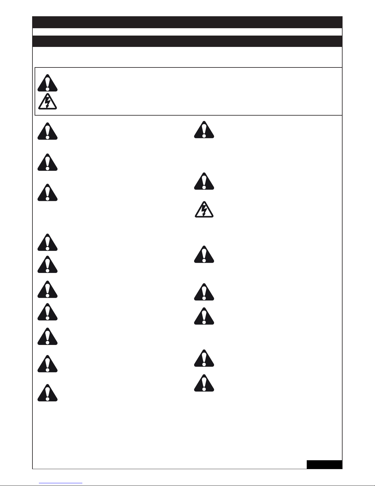
1/16 en
WARNING / ATTENTION
IMPORTANT FITTING AND OPERATING INSTRUCTIONS
PLEASE START BY READING THESE IMPORTANT SAFETY RULES
This safety alert symbol means „Caution“ - failure to comply with such an instruction involves risk of personal
injury or damage to property. Please read these warnings carefully.
This gate drive mechanism is designed and tested to offer appropriately safe service provided it is installed and
operated in strict accordance with the following safety rules.
Incorrect installation and/or failure to comply with the following instructions may result in serious personal
injury or property damage.
When using tools and small parts to install or
carry out repair work on a gate exercise caution
and do not wear rings, watches or loose
clothing.
Installation and wiring must be in compliance
with your local building and electrical
installation codes. Power cables must only be
connected to a properly earthed supply.
Entrapment protection devices MUST be
installed to protect anyone who may come
near a moving gate. Locate entrapment
protection devices to protect in BOTH the
open and close gate cycles. Locate
entrapment protection devices to protect
between moving gate and RIGID objects,
such as posts.
Please remove any locks fi tted to the gate in
order to prevent damage to the gate.
After the installation a fi nal test of the full
function of the system and the full function of
the safety devices must be done.
This drive cannot be used with a gate
incorporating a wicket door unless the drive
cannot be operated with the wicket door open.
Gate must not extend over public byway during
operation.
Lightweight gates must be substantially
reinforced to avoid gate damage. The best
solution is to check with your gate manufacturer
for an opener installation reinforcement kit.
Activate opener only when the gate is in full
view, free of obstructions.
Do not allow children to play near the gate.
Humidity and water destroy the control board.
Make sure under all circumstances that water,
humidity or dammed-up water cannot penetrate
the control board covering.
Frequently examine the installation for imbalance and signs of wear or damage to cables,
hardware and mountings. Do not use if repair or
adjustment is necessary. Gates which stick or
jam must be repaired immediately. Employ a
qualifi ed technician to repair the gate, never
attempt to repair it yourself.
Keep additional accessories away from children.
Do not allow children to play with pushbuttons
or remote controls. A gate can cause serious
injuries as it closes.
Disconnect electric power to the system before
making repairs or removing covers.
A disconnecting device must be provided in the
permanently-wired installation to guarantee
allpole disconnection by means of a switch
(at least 3mm contact gap) or by a separate fuse.
Make sure that people who install, maintain or
operate the gate drive and/or the control board
are qualifi ed and follow these instructions.
Keep these instructions in a safe place so that
you can refer to them quickly when you need to.
The full protection against potential squeeze or
entrapment must work direct when the drive
arms are installed.
This appliance is not intended for use by
persons (including children) with reduced
physical sensory or mental capabilities, or lack
of experience and knowledge, unless they have
been given supervision or instruction
concerning use of the appliance by a person
responsible for their safety.
Children should be supervised to ensure that
they do not play with the appliance.
Automatic drive – Keep away from the area of
the gate since it may operate unexpectedly.
SAVE THESE INSTRUCTIONS
Page 86
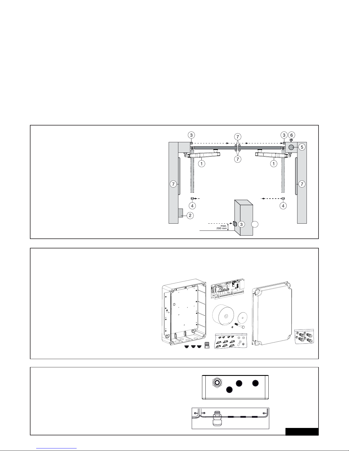
TECHNICAL DATA
Voltage: 230V~ ±10% 50-60Hz
Transformer: 230V/24V, 150VA
Output Motor: 24V/DC
Consumption max.: max. 400W (in operation)
Consumption Standby: max. 4 Watt (without accessories)
Supply accessories: 24VDc / 600mA max.
Operating temperature: -25ºC ÷ 55ºC
Modes: Standard, Automatic
Measurements: 250x75mm (without box)
Measurements Box: ca. 300mm x 220mm x 120mm
Protection class Box: IP45
Fuse: 2 x 2A fast-blow
Remote control: max. 170
Feasible frequencies: 433MHz, 868MHz
TYPICAL CONFIGURATION OF AN INSTALLATION:
1. Operators (LYN/SCS)
2. Control board
3. Photocell (active for closing), max. height 200 mm
First photocell.
4. Photocell (active for opening and closing), max. height 200 mm
Second photocell (optional).
5. Flashing light (optional)
Important visual information on the movement of the gate.
6. Key-operated switch or wireless keypad (optional)
Is mounted on the outside. The gate is opened by key or by
entering a number.
7. Contact strip (optional)
Safeguards the gate on being touched. Contact strips can be
mounted on the gate or on the pillars. If required, contact strips
must be mounted at a height of up to 2.5m.
2/16 en
CONTROL BOX
The control consists of several components.
- exterior installation box 1
- cover for box 1
- control 1
- transformer 1
- baseplate (pre-assembled) 1
- cable bushing large 1
- cable bushing small 3
- fastening clips 6
- screws 3,5 x 9,5 mm 4
- large washer 1
- screw large 1
- spring lock washer 1
- cable lug 1
- nut M8 2
- washer M8 1
- large closure screws 5
PREPARATION
Open the 4 pre-cut holes at the bottom of the casing
with a screwdriver or a similar device. Attach large
cable bushing on the left then the rest as shown in
picture. Humidity and water destroy the control. All
openings and cable bushings must be sealed
against water (waterproof). The control box with the
motor control is to be mounted with the cable
bushings facing down.
4
+
Page 87

RECOMMENDED PROCEDURE:
Fasten exterior installation box to wall, after previously measuring required distances and establishing correct position of drill-holes (Hardware
not included). Baseplate for transformer is already pre-assembled (A).
Push fastening clips in designated holes (B) .
Push controlboard on to fastening clips (C).
Fasten transformer on to baseplate using the large screw and large washer (D).
Put the 4 large closure screws through cover of the box. Fasten 2 of them (left or right) approx 2cm into the box.
After that the cover can be opened to the side (E).
Close box on a trial basis turning the screws all the way in. If the lid does not close completely, then the box is not fi tted to the wall evenly and is
therefore distorted. This must be corrected. It is very important for the box to be waterproof once closed.
3/16 en
6x
B
C
D
A
E
Page 88
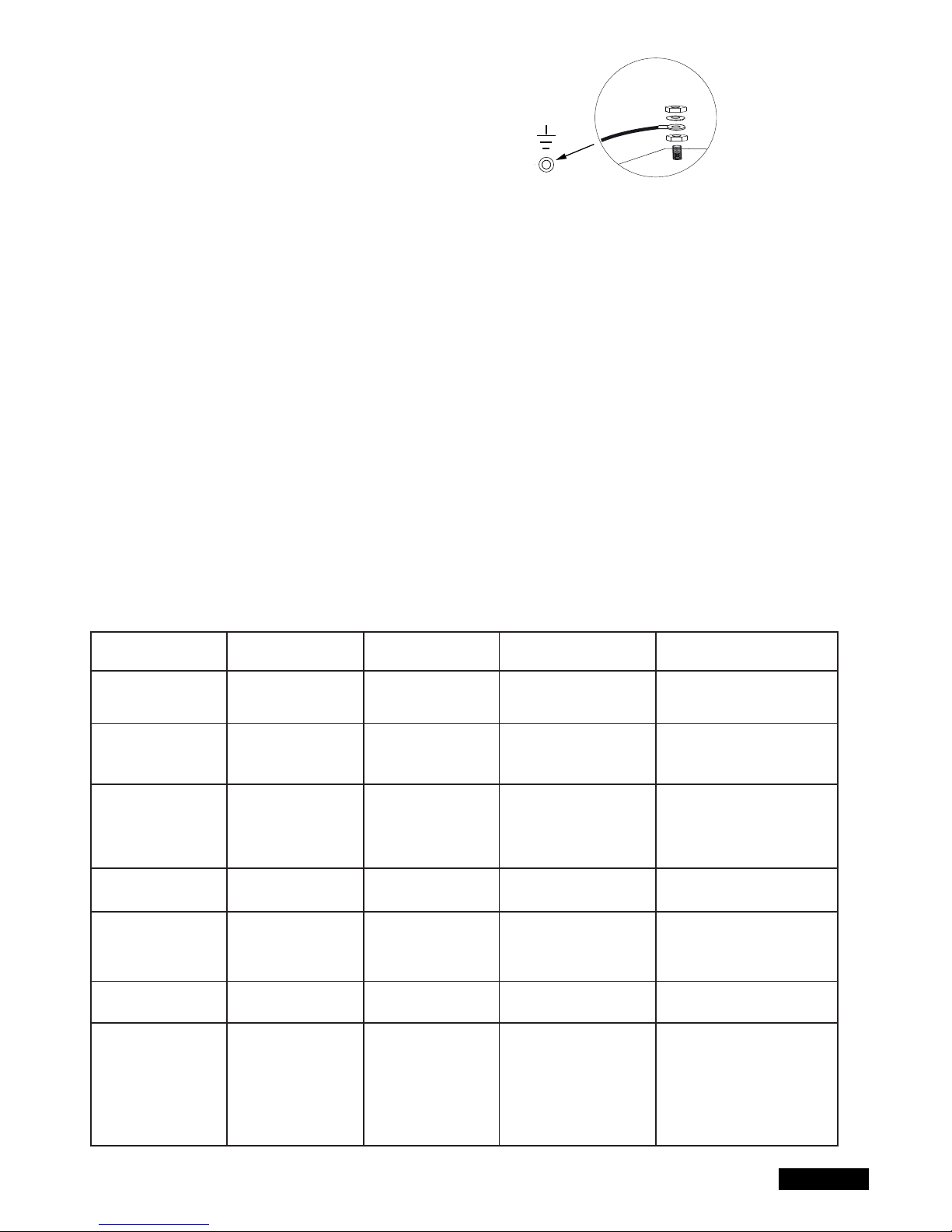
WIRING OF CONTROL / SUMMARY
a) start with 230Volts supply cable.
Run cable through large cable bushing on the lefthand side.
b) Attach cable eye to ground wire. Then connect ground wire to
base plate with washer and nut (exactly as shown in picture detail).
Connect all other cables to control.
CABLES AND WIRING
The usage of shielded cable in order to connect the motor to control board is highly recommended. Magnetic and inductive infl uence of the signal in
the cables can produce electric noise and may disturb the function of the gate .
Generally avoid:
- Control board location far away from gate.
- 230Volt and low voltage in the same power line. Not allowed by electrical rules.
- Wiring of the infrared sensors, switches, fl ashing lamps & electric locks require a cable separately from the motor wiring.
- Other wirings like telephone intercoms, lights for garden etc. must be in separate cables.
- Rigid copper cables especially when thicker diameters are diffi cult to manage during the installation and may result in bad connections with
functional issues. Use instead fl exible cables.
- Cable material not suitable for outside use. Use cables suitable for outside use and underground. Run the cables in conduits if the cable is not
suitable for placing in the ground (armoured or suitably protected). You may also consult your local electrician.
We recommend the following accessories:
- LA400-JB40E Kit for cable extension of one installation unit. Consists of 12m of cable 6-pole with identical colours, distribution box IP65,cable
screw joints and fastening material.
- 041ASWG-0482-50 Cable 50m for professional use. Consists of 50m of cable 6-pole with identical colours. Cut only as much as you need for the
current installation.
General wiring sizes:
The numbers mentioned in the table below are minimum requirements. It is always possible to use larger diameters.
- 230Volt Supply Power to controller: min. 0,75mm² 3-pole
- 230Volt Supply transformer installed separately (i.e. in the garage) and low voltage to gate. See table.
- Motor wiring: 2 wires min. 1,0mm², 4 wires min. 0,75mm² (or shielded cable)
- Electric locks: See table
- Switches, infrared sensors, fl ashing lamp: See table etc. min.0,5mm²
4/16 en
Operator Model
LYN, SCS, ART
motor wiring
SUB (underground)
motor wiring
Transformer separately
installed (in garage) and
low voltage supplied to
control board box.
Electric lock (12Volt)
wiring
External antenna
(Remove original
antenna of logic board)
Switches, Flashing lamp
etc.
Infrared Sensors
Distance
0m - 6m
2 x 1,0mm²
4 x 0,75mm²
2 x 1,0mm²
3 x 0,75mm²
0,75mm²
0,75mm²
Coax cable (Satellite
cable)
50 Ohm
0,5mm²
0,5mm²
Distance
6m - 10m
2 x 1,0mm²
4 x 0,75mm²
2 x 1,0mm²
3 x 0,75mm²
0,75mm²
0,75mm²
Coax cable (Satellite
cable)
50 Ohm
0,5mm²
0,5mm²
Distance
10m - 12m
Normal
Wiring
Use shielded cable for
the 3 smaller motor wires
1,0mm²
1,0mm²
Coax cable (Satellite
cable)
50 Ohm
0,75mm²
0,75mm²
Distance
12m – xx
Max. 15m
Use shielded cable for the 4
smaller motor wires.
Use shielded cable for the 3
smallermotor wires
Max. 30m; Min. 1,5mm²
Gate weight maximum 50% of
maximum motor power rating.
Max. 30m; Min. 1,5mm²
Coax cable (Satellite cable)
50 Ohm
(max. 25m)
Min. 0,75mm²
Max. 30m
Min. 0,75mm²
Max. 20m
Page 89
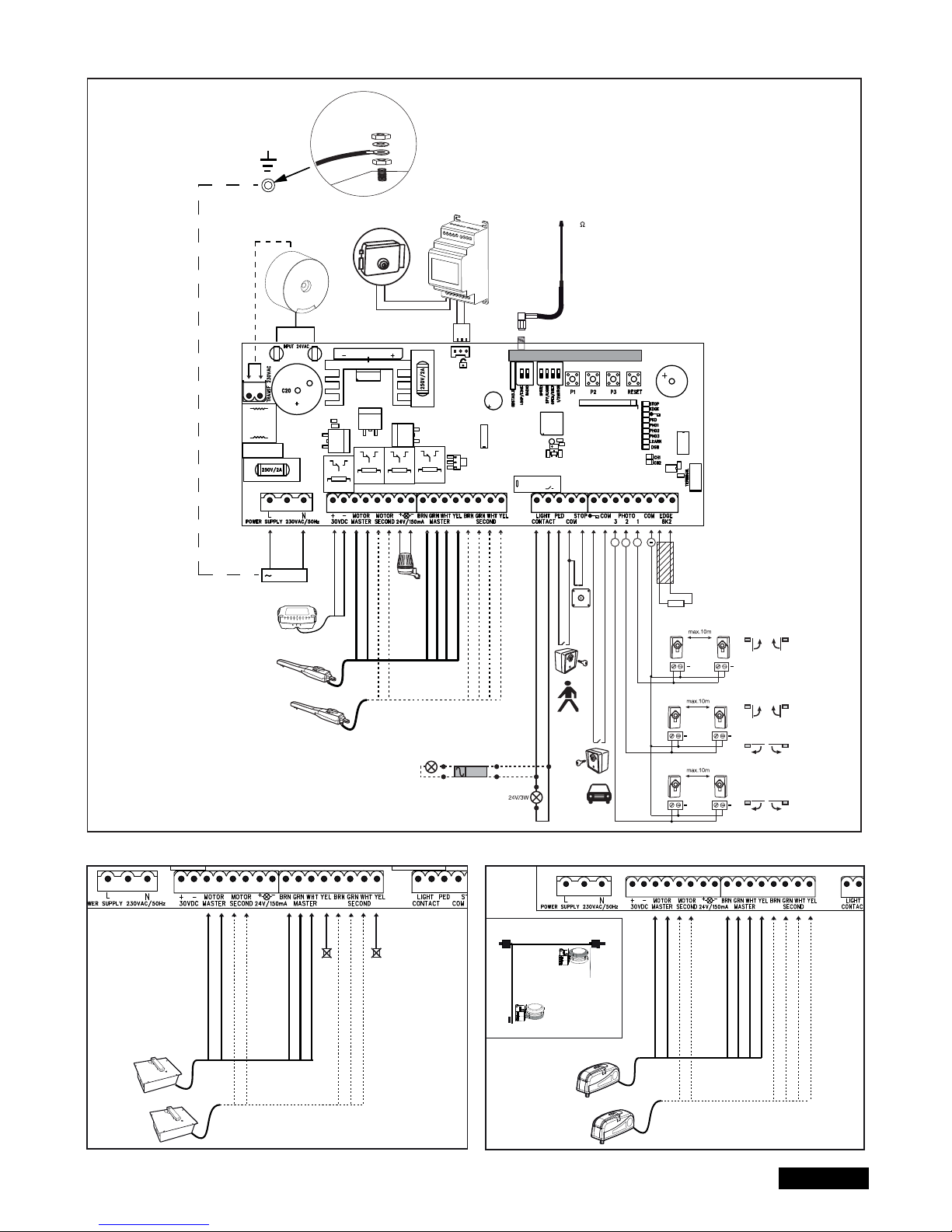
5/16 en
WIRING DIAGRAM
LYN/SCS
230VAC
PE
PE
Model
203285
Ω
8.2
+
+
+
+
+
+
+
Relay
+++
+
-
RED
RED
BLUE
BLUE
Model
CM475
BROWN
GREEN
WHITE
BROWN
GREEN
WHITE
YELLOW
YELLOW
RADIO MODULE
Model
207399
230 VAC
50
RED
RED
BLUE
BLUE
BROWN
GREEN
WHITE
BROWN
GREEN
WHITE
not required
not required
RED
RED
BLUE
BLUE
BROWN
GREEN
WHITE
BROWN
GREEN
WHITE
YELLOW
YELLOW
ART
SUB
Closed position
Open position
external
battery
Page 90

FUNCTIONALITY OVERVIEW OF THE PUSH BUTTONS P1, P2, P3 & RESET
P1+P2+P3
P1
P1 + P2
P2 + P3
P1 + P3
P2
P3
DIP „RADIO“ + P1
DIP „RADIO“ + P2
RESET
Manual operation. The gate wings can be moved electrically in a manual mode. Activate Function: Push P1+P2+P3
simultaneously. The LED LEARN starts to fl ash as long as feature is activated. Button P1 operates Motor1. Button P2 operates
Motor2. Deactivate: Wait for 20 seconds or disconnect logic board power. If wings close at fi rst reverse wires red and blue.
For automatic programming of the automatic travel distance limits of the gate.
For the advanced programming of the travel distance limits of the gate
Electric lock delay time
Wing delay adjustment.
Automatic closing time. Requires also P2 to confi rm.
Software-reset to factory defaults. Push & hold for 10 seconds. Does not reset the remote control memory (see section “radio”).
Programming Remote for Channel 1. Command for both motors (wings)
Programming Remote for Channel 2. Command for single motor (Motor1).
Program Internet Gateway or Door Monitor Note: The RESET button does not perform a reset of this particular control board
to factory defaults . It is only meant to program the Internet Gateway and the Door Monitor. See function P3 for resetting the
board to factory default settings.
Button Function
6/16 en
DESCRIPTION OF TERMINALS
DESCRIPTION FUNCTION
L connector L 230V supply
N connector N 230V supply
30VDC connector for an external battery
Motor MASTER motor 1 (master opens fi rst) red/blue
Motor SECOND motor 2 (Second opens second) red/blue
To check correct polarity refer to section basic setting and
functionality P1+P2+P3 & RESET
24V/150mA fl ashing light (accessory)
Motor1 MASTER
BRN brown cable
GRN green cable
WHT white cable
YEL yellow cable
Motor2 SECOND
BRN brown cable
GRN green cable
WHT white cable
YEL yellow cable
Light Contact gate monitor/ yard lighting
PED key switch
COM negative pole
STOP stop switch
Key symbol key switch
COM negative pole
PHOTO3 photocells 3 (open)
PHOTO2 photocells 2 (close & open)
PHOTO1 photocells 1 (close)
COM negative pole
EDGE safety edge with 8.2KOhms
8.2kOhms
E-lock symbol connection for E-lock control board
INPUT 24VAC 24V power input from transformer.
can be connected with any polarity.
Transformer 230VAC 230V supply to transformer. Can be
connected with any polarity.
250V/2A fuse 250V/2A fast-blow (2x included)
DESCRIPTION OF LED´S (LIGHT EMITTING DIODE)
DESCRIPTION COLOUR STATUS
Stop green Stop Switch
ON: Stop Active
OFF: OK (Requires wire bridge if
no switch is connected)
Edge green Safety Edge 8.2KOhm
ON: Activated
OFF: OK (Requires 8.2KOhm
resistor if not used)
“Key symbol” red Key-switch 2-wing opening
ON: Activated
OFF: OK
PED red Key-switch 1-wing opening
ON: Activated
OFF: OK
PHO 1 red Photocell 1 (close)
ON: OK, photocell
connected (no problem)
OFF: No photocells connected
PHO 2 red Photocell 2 (open & close)
(Refer to photocell 1)
PHO 3 red Photocell 3 (open)
(Refer to photocell 1)
LEARN yellow Programming indicator
ON: (fl ashing)
programming is active
OFF: off
DGN red Diagnostic, Refer to page 15
CH1 red Remote control
programming 2-wing opening
ON: New remote can be
programmed
OFF: off
CH2 red Remote control programming
1-wing opening (Refer to CH1)
Page 91

7/16 en
OPTIONAL ACCESSORIES (also refer to wiring diagram)
RADIO TRANSMITTERS MODELS (OPTIONAL):
TX2EV, TX4EV, TX4UNI (remote controls), 747EV (wireless keypad), 128EV (2-channel wall control)
FLASHING LAMP (OPTIONAL) MODEL: FLA24-2, FLA1-LED
A fl ashing lamp can be connected to the control board (Terminals: 24 V / 150 mA). It indicates gate movement. The fl ashing light should be
mounted as high as possible and in good clear view. The control board emits a constant signal that the lamp converts to a fl ashing signal.
KEY SWITCH (OPTIONAL) MODEL: 100010, 100027, 100034, 100041
The system can be operated by key switch (Terminals: key symbol and COM). Also see OPEN/PED under “DIP SWITCH SETTINGS”.
STOP SWITCH (OPTIONAL) MODEL: 600084
A stop switch to stop the movement of the gate in any direction can be connected to this output
SAFETY EDGE (OPTIONAL) MODEL: 600046, 600053, 600077, 600060
(DIP LOOP/EDGE must be off)
A safety edge working according to the 8.2 kilo ohm principle can be connected to the control board (Terminals: Stop / 8,2 kOhm), i.e. a 8.2 kilo
ohm test resistor is attached to the end of the safety edge. It ensures that the electric circuit is monitored permanently. The control board is
supplied with an 8.2 kilo ohm resistor installed. Several safety edges are connected in series.
PHOTOCELLS (OPTIONAL) MODELS: 771E, 772E
The use of photocells is recommended. Use either model 771E or 772E which is also part of Safety Accessoy Kit APLUS-EV
SAFETY ACCESSORY KIT (OPTIONAL): APLUS-EV
The control board is already supplied with an antenna as standard. For special operating distances, an external antenna from the APLUS-EV
accessory kit (includes Photocell 772E, Flashing Light FLA1-LED, and External Antenna SWG-ANT-EV) can be connected as shown in the
wiring diagram.
myQ (OPTIONAL)
(only with 828EV Internet Gateway):
Allows operating the gate opener via Internet or compatible smartphnone.
DOOR MONITOR (OPTIONAL)
(only with 829EV door monitor):
allows optical and acoustical monitoring of the gate position. The gate can also be closed with the device.
BACKUP BATTERY (OPTIONAL) :
The terminals serve to reload an externally installed storage battery.
The integrated recharger is loaded and in case of power failure the battery provides power. A new fully charged storage battery may provide
power for more than 24 hours. Storage batteries are subject to deterioration and lose capacity. Due to extensive use they lose capacity even
faster. Replace storage batteries after approx. 2-3 years.
E-LOCK (OPTIONAL)
The control board allows the use of a 12V E-lock. (instructions included with E-lock). A transformer (207399) must be connected for the Elock
on the main board. In case the gate pushes too hard for the e-lock to open, a special function can be programmed. Activation time
adjustment: Push P2 and P3 together and hold for approx 5 seconds, and count the number of clicks you hear. The click sound is produced
from a relay (light relay).
1 click = approx. 4 seconds power to e-lock (factory setting)
2 clicks = gate closes for 1 second, then opens. Furthermore, after reaching the closed door position, the drive presses briefl y to support the
snap-in of the electric lock. Note: The door should be equipped with ground stops.
GATE MONITORING or YARD LIGHTING (OPTIONAL)
The Terminals have two functions depending on the position of the DIP Spy/Light. Refer to step “DIP SWITCH SETTINGS” in this manual.
The output has no separate power supply and should be charged only up to 24V.
Gate Monitoring / Status of the gate (Spy)
An LED or 24V/3W max lamp (or relay) can be connected to the terminals to indicate the status of the gate
LED OFF = gate close
LED blinking slow = gate opening
LED ON = Gate open
LED blinking fast = gate closing
Yard lighting / Courtesy lamp for 120 seconds
An 24V/3W max lamp (or relay) can be connected to have 120 seconds output to the terminals, when the gate is receiving a command to Open/Close.
After this time, it will switch OFF automatically
CAUTION: output can be charged only up to 24V/3W or relay must be interposed
Page 92

8/16 en
PHOTOCELLS (OPTIONAL) MODEL: 771E, 772E
The photocells are for safeguarding the gate and must be used. The fi tting location
depends on the gate’s design. EN12453 specifi es that a pair of photocells must be in-
stalled at a height of 200 mm and activated to “Close”. The photocells consist of a transmitter and a receiver and must be opposite each other. The photocell is mounted on
the wall using small screws and wall plugs. To enable the “Automatic Closing” function,
the Chamberlain failsafe photocell must be installed. The Chamberlain failsafe system
(2-cable system) has small LEDs (light) that can be seen from the outside on both sides
to indicate the status of the photocell.
Programming of IR sensors:
- connect IR sensors
- program the travel of the gate.
Deletion of IR sensors:
Disconnecting already connected IR sensors will cause the control board to
block the functionality of the terminals it was connected to.
To delete IR sensors correctly:
- disconnect IR sensors
- cut control board from current shortly
- program the travel of the gate.
Diagnosis of the photocell
LED constant = OK
LED fl ashes = photocell disables control board
LED off = no current, incorrect connection or polarity
Diagnosis on the control board
LED off = OK no photocell connected
LED fl ashes = photocell disables control board
Connection between 1 & COM:
Active when gate is closing (reverses gate to open)
Connection between 2 & COM:
Active when gate is closing and opening
Connection between 3 & COM:
Active when gate is opening (holds gate in present position until photocell
is cleared; continues when cleared)
RADIO AND RADIO PROGRAMMING
PROGRAM / DELETE REMOTE CONTROLS
The receiver has two channels CH1 and CH2. Using the different channels
enables the opening of one wing resp. both wings. For example, if CH2=P2
receives the code from the remote control only one wing will open. Choosing
a different button on the remote control in combination with CH1=P1 will
cause both wings to open.
PROGRAMMING
1. Switch on DIP “RADIO”
2. Briefl y push button P1 (for CH1) or P2 (for CH2) and the
respective LED lights up.
3. Press and hold a selected button on your remote control until
LED goes out after 5 times fl ashing. Done!
Repeat for all remote controls (a maximum of 85 remote
controls can be programmed to each channel).
Important: To fi nish programming, Switch off DIP “RADIO”!
Note: Make sure not to program the same remote control button to
CH1 and CH2, otherwise the gate will work improperly.
DELETE
- Switch on DIP “RADIO”.
- Press and hold learn-button P1 for approx. 10 seconds
until LED goes out again. All codes programmed are deleted.
To confi rm both LEDs CH1 and CH2 fl ash 8 times.
- Switch off DIP “RADIO”.
RADIO MODUL
E
ON ON
RADIO MODUL
E
ON ON
RA
ON ON
RA
ON ON
+
+
+
+
+
+
+
+++
Page 93

9/16 en
PROGRAM INTERNET GATEWAY myQ
Using the RESET -Button on the control board
1. Connect the ethernet cable to the LiftMaster Internet Gateway
and the router.
2. Connect power to the LiftMaster Internet Gateway.
3. Create an online account on the latest Liftmaster MyQ smartphone
application or on www.liftmaster.eu. It is recommended to use the
smartphone as it will allow you to stand close to the gate while programming
4. Register the LiftMaster Internet Gateway.
5. Click on „Add new device“ and follow the steps given by the
application or on the webpage.
6. Note: When pushing the RESET-Button you will hear a beep and the
LEDs CH1 and CH2 fi rst go on, then after matching, the LEDs will
blink 3 times and go out.
7. The App will tell you if programming was successful and will prompt
you to assign a name to the gate.
PROGRAM DOOR MONITOR
Using the RESET -Button on the control board
1. Connect power to the door monitor.
Position the door monitor in a convenient visible place inside the house.
If this place is too far from the gate opener the connection may not be
possible or is often interrupted.
Choose a more convenient place.
2. Press and release the „LEARN“ button on the back of the door monitor.
Red and green LED blink alternately.
Within 60 seconds press and release the RESET button on the control board.
To confi rm programming red and green LED on the door monitor are on.
DELETE DOOR MONITOR
Press the „LEARN“ button on the back of the door monitor for at least 10 sec.
A short „beep“ confi rms that deleting was successful.
ADIO MODULE
ADIO MODULE
Page 94

LOOP DETECTOR
Switch on DIP LOOP / EDGE
Loop detectors react to metal and the most common use is for cars
or trucks but not for bikes or pedestrians.
Exit loop / Gate Opening Loop A
An exit loop is behind the gate and opens the gate when closed,
keeps it open or re-opens the gate.
The DIPs OPEN/STEP and LOOP/EDGE must be on. The gate
requires installed photocells and the closing of the gate shall be
activated by the automatic close timer.
Safety/Interrupt loop and Shadow loop B, C
Safety loops can be used to detect cars or truck but do not comply
with regulations as single protection since they do not detect people.
The loop detector control board output is wired as NO signal to the
8.2KOhm safety edge output. In case you use safety edges as well:
Check the functionality you need before installation!
Interrupt loop => DIP OPEN/STEP must be on.
Shadow loop => DIP OPEN/STEP must be off.
Other options for loop detectors can be requested from our service
department.
10/16 en
RN WHT YEL
ASTER
BRN GRN WHT YEL
SECOND
COM
PHOTO
3 2 1
C
LIGHT
CONTACT
PED
COM
STOP
NO
Model
203292
Model
203292
RN WHT YEL
ASTER
BRN GRN WHT YEL
SECOND
COM
PHOTO
3 2 1
COM EDGE
8.2KΩ
LIGHT
CONTACT
PED
COM
STOP
NO
COM
NC
A
B
C
A
B C
RADIO
ON ON
RADIO
MOD
ON
RADIO
MOD
ON
Page 95

DIP SETTINGS
1 / 2 Motor
Select if 1 or 2 motors are connected to the control board
OFF: 2 Motors connected
ON: 1 Motor connected
OPEN/STEP
Changes the programming and reaction of the gate on commands.
For the use with loop detectors please refer to the loop detector
instruction fi rst.
Step Mode: The gate starts to open if a command is received, next
stop, next closes, next stop, next open…….
OPEN Mode: The gate will not react on a command during the travel
to the gate open position.
OFF: STEP
ON: OPEN
LIGHT/SPY
Gate Monitoring / yard Lighting Select if the function is used or leave free.
OFF: LIGHT(yard lighting)
ON: SPY (gate monitoring)
OBSTACLE
Factory-equipped with wire jumper. Disabling increases the
operating power at the control. CAUTION: If the jumper is
disabled, the door system should be secured with additional
safety devices (contact strip, etc.).
LOOP/EDGE
Select for desired device.
OFF: EDGE
ON: LOOP
SPEED
Select for the type of motor you intend to use.
OFF: Slow ART, LYN, SCS, SUB
ON: Fast LYN, SCS, SUB
RADIO
The DIP “RADIO” is required to program remote controls.
For programming procedure please refer to page 8, section “radio”
OFF: No programming of remote controls possible
ON: Programming of remote controls possible
Important: Switch off DIP “RADIO” if not in use!
Wing Delay Adjustment
The delay of one wing is required to open and close the wings correctly
and to operate the wings with a safe distance from each other. A larger
distance may be required when the mechanical installation distances
are different between the wings or wing length is different. The delay
time in opening direction is fi xed. The closing is adjustable
Push P3 and P1 together and hold for approx 5 seconds, and count
the number of clicks you hear. The click sound is produced from a
relay (light relay).
1 click = small delay, about 4÷8 seconds (factory default settings)
2 click = medium delay, about 8÷12 seconds
3 click = big delay, about 12÷16 seconds
4 click = total delay, wing 1 will close only when wing 2 is completely closed
Delay in opening direction is always 3 to 5 seconds.
5 click = no delay in opening and closing (wings move simultaneously)
Repeat the procedure if required.
11/16 en
RADIO MODULE
RADIO MODULE
ON ON
Page 96
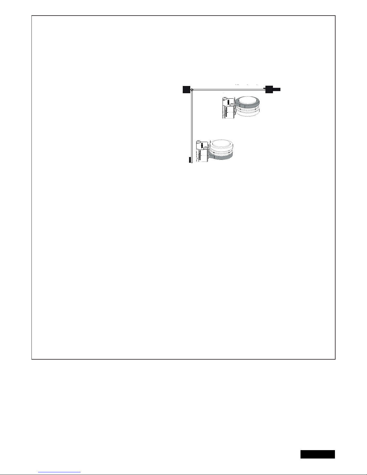
12/16 en
INITIAL OPERATION
BASIC SETTING
Proceed step by step. If you are not sure, start again at the beginning. Take suffi cient time to make these settings.
1. Are all components required for operation connected? Motors, photocells, safety contact strip, stop switch.
2. If your installation consists of only 1 gate (wing) the DIP “1 / 2 Motor” must be on (also refer topage 11, DIP SWITCH SETTINGS).
3. Make sure that nobody is present in the range of the gates.
4. Close the gate/s and attach motor/s.
ART:
- Reference point or “passpoint” has to be adjusted to allow
a successful travel distance programming. The cams under
the cover of the ART need to be positioned correctly. The top
cam clicks the micro switch fi rst and the bottom cam as second.
The micro-switches pushed by the cam shall not be pushed
(clicked) at the same time and shall be not pushed in the end
position of the gate. Twist the cams by using a pair of pliers or
with a large fl at screwdriver.
- Disengage the gate using the release key for this adjustment.
- In case the drive arms are, after this installation step, re-located
the cam position has to be checked if a further adjustment is
required.
- DIP settings for ART: DIP SPEED off!
ART will not work if DIP SPEED is on.
SUB (Underground):
- DIP setting: DIP SPEED on for faster gate movement or off if gate is heavy or safest way of operating is
required. Can be changed any time later after completion of the installation.
LYN-SCS Operator:
- DIP setting: DIP SPEED on for faster gate movement or off if gate is heavy or safest way of operating is required.
Can be changed any time later after completion of the installation.
Now connect the mains supply (230V) to the control board.
BASIC SETTING:
1. Press buttons P1, P2 and P3 simultaneously for approx. 2-3 seconds until yellow LED fl ashes.
2. Monitor the gate. Press and hold P1 for 1-2 seconds. The wing with motor 1 opens. If motor 1 closes, it is wired
incorrectly and the red and blue wires of the motor cable must be reversed. (Caution: Disconnect Power!)
Repeat steps 1 and 2. Leave gate/s in partially open position.
NOTE: General operation – if you release the button, the gate will immediately stop. By pressing the button again the gate will
move in the opposite direction until you release the button, and so on.
3. Press and hold P2 for 1-2 seconds. The wing with motor 2 must open. (Do not open gate completely, only short
distances.) If motor 2 closes, it is wired incorrectly and the red and blue wires of the motor cable must be reversed.
(Caution: Disconnect Power!)
Repeat steps 1 and 2. Leave gate/s in partially open position.
NOTE: The control board is active for this manual setting mode for approx. 20 seconds. If necessary, start again by pressing P1,
P2 and P3 simultaneously.
Now check the following:
1. SCS only: During opening the front housing must not touch the gate. Stop opening several times and check. If housing
touches the gate dimensions A/B must be checked and if necessary, underlay the gate pillar with fl at washers in order to
enlarge clearance.
2. Both wings must open completely. Do not open the wings too far! If there are no stops, choose and mark a position for
maximum opening.
3. SUB (underground operator) only: Now adjust your hard-stop in the box.
Wait until learn-LED goes out (20 seconds after a button was pressed).
Cl
osed pos
iti
on
Open position
gate open
gate closed
Page 97

13/16 en
PROGRAMMING TRAVEL DISTANCES “SIMPLE I”
NOTE: End stops must be available in CLOSED and OPEN modes.
1. Wings must be closed
2. Press P1 until wing / motor 1 starts opening (learn-LED fl ashes)
Automatic programming starts (slow travel)
Wing 1 moves to the stop in OPEN position
Wing 2 moves to the stop in OPEN position
Then wing 2 moves to the stop in CLOSE position.
Then wing 1 moves to the stop in CLOSE position.
When the learn-LED goes out the programming has fi nished.
PROGRAMMING TRAVEL DISTANCES “SIMPLE II”
NOTE: If there are no stops at the OPEN position, the wing should be stopped at opening angle of 90 degrees.
1. Both wings must be closed.
2. Press P1 until wing / motor 1 starts opening
3. Press P1 hard when wing / motor 1 reaches OPEN position. Wing 2 starts.
4. Press P1 hard when wing / motor 2 reaches OPEN position. After that wing 2 closes automatically. The wing 1 closes automatically.
5. The motors “learn” the CLOSE position automatically.
If required, individual CLOSE positions can be programmed as well. Press P1 hard at the desired CLOSE position for each wing.
When the learn-LED goes out the programming has fi nished.
PROGRAMMING TRAVEL DISTANCES “ADVANCED”
NOTE: In this mode P1 must be pressed 9 times.
With every time the button is pressed a position (time) is stored. (This allows programming of SOFT-STOP (slow travel) in order to adjust to
application. Long or short phases of SOFT-STOP are possible.
1. Both wings must be closed.
2. Press P1 and P2 for approx.5-6 seconds until wing / motor 1 starts opening. Release buttons!!!
3. Press P1 again. SOFT-STOP for wing / motor 1 in OPEN direction starts at this point.
4. Press P1 again when OPEN position is reached.Now wing / motor 2 starts automatically to open.
5. Press P1 again. SOFT-STOP for wing / motor 2 in OPEN direction begins at this point.
6. Press P1 again when OPEN position is reached. Now wing / motor 2 starts closing automatically.
7. Press P1 again. SOFT-STOP for wing / motor 2 in CLOSE direction begins at this point.
8. Press P1 again when CLOSE position is reached. Now wing / motor 1 starts automatically to close.
9. Press P1 again. SOFT-STOP for wing / motor 1 in CLOSE direction begins at this point.
10. Press P1 again when CLOSE position is reached. Done!
NOTE: If one wing reaches a stop and button P1 is not pressed, then the motor moves towards the stop and stores this position automatically.
Page 98
14/16 en
COMPLETION OF INSTALLATION / PROGRAMMING
Once the travel distances are programmed, the remote controls can be programmed as well. (Refer to RADIO AND RADIO PROGRAMMING ).
1. You can now let the door run 2 complete cycles by pressing a key on the remote or a connected switch and observe the process.
Close the door again, WITHOUT making another setting.
2. If all adjustments are done, check operation of photocells, switch, fl ashing light, remotes, accessories, etc.
3. Advise people using the gate with regard to gate operation, safety functions and how to release the gate in order to operate it manually.
TIMER TO CLOSE (AUTO-CLOSE)
NOTE: Only possible with connected photocells (1 + COM). Time frames from 2 seconds up to 120 seconds are possible.
Activate:
1. Press and hold P2 until yellow LED starts fl ashing
2. Now count the time you wish to program
3. Press P2 again. Done!
Deactivate:
1. Press and hold P2 until yellow LED starts fl ashing.
2. Press P3. Yellow LED goes out. Done!
FORCE / TORQUE OF MOTOR
Thrust of the motor is set automatically while programming the travel
distance. Thrust can only be modifi ed by programming the travel
distance again. If gate movement is impeded by weather or changes
to the installation (rust or inappropriate lubrication) it may have to be
repaired.
The control board complies with the latest EU guidelines.
One of these guidelines specifi es that the closing forces
at the gate edge must not exceed 400N (40 kg) for the last 500 mm
before the door is CLOSED. Above 500 mm, the maximum force at
the gate edge must not exceed 1400 N (140 kg). If this cannot be
ensured, a safety edge must be mounted on the gate at a height up
to 2.5 m or on the pillar on the opposite side (EN12453).
DISPOSAL
The packaging is made from environmentally friendly materials. It can be disposed of in the local recycling bin. According to the European
Directive 2002/96/EC on waste electrical and electronic equipment, this device must be properly disposed of after use to ensure the reuse of
materials. The information on the possibilities of this waste disposal is provided by the local government or municipality.
BATTERY DISPOSAL
Batteries and rechargeable batteries may not be disposed along with domestic waste, but are
obliged to be returned.
After use they can be returned free of charge locally e.g. in trade or at municipal collecting points.
Batteries and rechargeable batteries are marked with a crossed waste container as well as with the
chemical symbol which describes their toxic element, “Cd” for cadmium, “Hg” for mercury and “Pb” for lead.
12VDC
Pb Cd Hg
Page 99

15/16 en
INDICATION OF THE DIAGNOSIS LED
The LED diagnostics show the fi rst upcoming issue. If several issues are existing the LED diagnostics may not show them.
Indication
1x blinking
2x blinking
3x blinking
4x blinking
5x blinking
6x blinking
7x blinking
8x blinking
9x blinking
10x blinking
11x blinking
12x blinking
13x blinking
14x blinking
15x blinking
Description
Motor 1 has insuffi cient connection to control board
Control board does not see motor sensor.
Travel distance programming was not successful
Motor 2 has insuffi cient connection to control board
Limits for motor 2 have not been accepted
A: After or during programming travel: Wing 1 did not
open wide enough and did not meet the integrated
passpoint which is located inside the operator halfway above the spindle.
B: Motorcables have insuffi cient connection to contol
board
Yellow or white cable not wired or badly connected
Limits for motor 1 have not been accepted
Travel has not been programmed
The process of programming has been interrupted
Force to operate the gate is too high
A: Gate is out of order
B: Gate is rough-running
C: Gate stopped through windload
D: Wrong mechanical installation
Photocells 1 block installation + LED PHO1 =OFF
A: Object blocks photocells
B: Alignment of the sensors is incorrect
C: Power supply to photocells is insuffi cient
Photocells 2 block installation
Photocells 3 block installation
Emergency stop switch blocks installation
Safety edge blocks installation
A: Object obstructs safety edge
B: Defective safety edge
C: Power too low or broken wire in supply
Power supply to control board is too low
A: Defective supply 230V or malfunctioning contact
B: Broken wire in supply cable (copper cable)
C: The battery (accessory) to operate the gate whilst
power failure is dead.
EEPROM Fault
Power up failed
Only LYN/SCS
Release lever OPEN
Defect on relay or major electrical component
A: Overload
B: Bad wiring (wrong)
C: water in photocells (bad installation)
D: a photocell was connected before but not removed
(disconnected)
Remedy
Cables not wired or badly connected.
Check terminals precisely. Consider wire lengths
The gate must be closed completely before programming the
travel distance
Refer to 1x blinking
A: Open gate wide enough when programming the travel (50%
over maximum)
B: Check terminals precisely. Consider wire lengths
C: See 1x blinking (wiring)
Refer to 3x blinking
The gate must be closed completely before programming the
travel distance.
Refer to 5x blinking also
A: Repair gate
B: Check if gate can be easily moved
C: Do not operate gate in very windy conditions
D: Reprogram to achieve suffi cient level of force
A: Remove object
B: Check alignment
C: Check cable widths and contacts
Refer to 7x blinking
Refer to 7x blinking
A: Check wiring
B: Check basic setting of control board (DIPs)
A: Remove object
B: Check wiring. Check resistor 8.2KOhms
C: Check basic setting of control board (DIPs)
A: Check electric contact
B: Check by electrician
C: Allow battery to charge 24 hours
Replace contol board
Close (re-connect) release lever
Replace logic board
Check wiring
Reprogram the travel distance from gate fully closed
Page 100

16/16 en
FAQs
Pressing P1, P2 and P3 does not show any reaction
The gate opener doesn’t respond at all; no LED is
on.
Immediately after the gate has started moving, it
stops and reverses.
Gate can only be opened
“
Timer to close” doesn’t work.
The control board does not work any more using
the transmitter, only with the switch and even then
only as long as a button is pressed and kept
pressed.
The gate opener doesn’t respond at all, although
the controller has been connected (LEDs are on).
Control board does not work with transmitter
Control board does not work
Gate doesn’t open completely
Travel distance can’t be programmed
The operator sometimes movess slowly
Possibly power failure.
Obstacle in area of gate.
Gate rough running (consult dealer)
photocell blocks
Photocell, a safety edge or the emergency
stop disables the control board
Only one photocell was connected for OPEN
1. Remote control not programmed.
2. LEDs indicate a fault.
3. Photocell connected incorrectly.
4. Motor terminal possibly not connected
properly.
1. transmitter not programmed
2. photocells block
3. DIP “RADIO” is on
travel distance not programmed
Gate heavy / rough running
1. DIP setting not correct
2. Motor wiring not correct or cable broken
3. Diagnostic LED
4. Electric noise in wiring disturbs
5. Gate moves for 1 second only and stops
without reversal during programming
6. ART only: Passpoint adjustment incorrect
7. ART only: Motor disengaged
Powerfailure
DIP “RADIO” must be off
1. Check conductor and zero conductor.
2. Check house fusing.
Check gate area for objects
check photocells
reprogram travel distance
Function and connection must be
checked
Only works if the 2-cable photocell 771E(ML)
or 772E(ML) installed.
At least 1 pair of photocells active in
OPEN or CLOSED must be connected
1. Programming remote control.
2. Find and rectify fault(s) (see description of
diagnostic LEDs).
3. Check photocell connection / programming.
4. Check terminals and connections.
1.Program transmitter
2.Check photocells, check diagnostic LEDs
3. DIP “RADIO” must be off.
Program travel distance. See initial
operation / diagnosis LED
re-program travel distance
consult dealer/specialist
1. Check manual, especially “1/2 Motor”
2. If motor is moving check brown, green, white,
yellow cable. Test with different cable to exclude that the defect is the cable in the ground.
Or connect for testing the motor direct to the
control board without extension cable.
3. Check diagnostic for route cause.
4. Refer to solution 2 and if applicable change
wiring type or routing. Verify wiring with manual
recommendation.
5. Not enough electrical power (volts) or bad
wiring. Refer to solution 2.
6. Adjust passpoint cams in motor. Refer to
ART manual.
7. Engage motor. Refer to ART manual.
Common procedure. After powerfailure the
operator performs a selftest. Depending on
the operator model this can take a few
seconds or a complete cycle. Do not interrupt
this test via remote control or switch,
otherwise the limits may change. If this is the
case reprogram travel distance using P1.
The remote control’s range is too short. The installation of an external antenna is recommended as the controller with the short cable
antenna is located either behind the post or near ground level in most cases. The optimum
location of the antenna is as high as possible in all cases. An appropriate antenna with
installation kit can be obtained as an accessory.
The gate must follow a slope. Not recommended! Change gate! The gate can move in an uncontrolled (dangerous) manner if
the gate opener has been released. A stronger force is needed in the upwards direction of the
slope and then, in the opposite direction, the gate opener’s force is too strong.
The gate post is so thick that I am unable to Reduce post thickness or shift gate location
comply with the requisite A+B dimensions.
 Loading...