

Page 1
OVERVIEW
The fail safe plug-in loop detector allows the gate to stay open when vehicles are
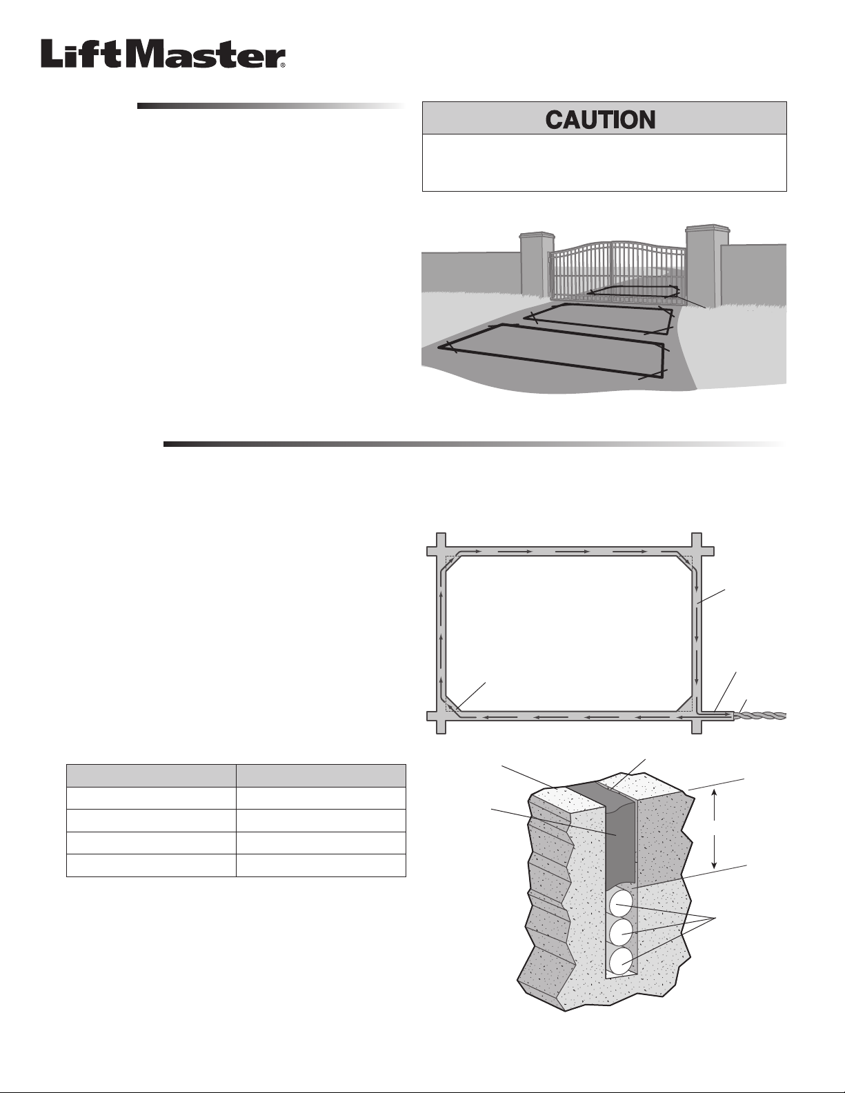
obstructing the gate path. The loop can be set to function as a Shadow Loop, an
Interrupt Loop, or an Exit Loop. For use with CSW24V and CSL24V gate operators
ONLY.
SHADOW LOOP: Positioned in the path of a swing gate and is active ONLY when
the gate is in the open position. Only used in swing gate applications.
INTERRUPT LOOP: Positioned outside the property and when activated will open
a closing gate.
Plug-in Loop Detector
MODEL LOOPDETLM
To prevent DAMAGE to circuit board, loop detectors and/or the gate operator,
installation MUST be performed by a trained gate systems technician.
EXIT LOOP: Positioned inside the property and when activated will open a closed
Shadow Loop
Interrupt Loop
gate.
Exit Loop
(Inside Property)
INSTALLATION
The loop itself must be a continuous length of wire without any breaks or splices. The loop wire can be 14, 16, or 18 gauge stranded wire with either a cross-linked
polyethylene (XLPE) or polyester insulation.
Mark the loop layout on the pavement. Remove sharp inside corners that can
1
damage the loop wire insulation.
Determine the thickness of the pavement to ensure that the depth of the cut
2
will not exceed the thickness of the pavement before attempting to cut the loop
slots. Set the saw to cut a depth (typically 2-2.5 inches) that will ensure a
minimum of 1 inch from the top of the loop wires to the pavement surface. The
saw width must be larger than the diameter of the loop wire to avoid damage
to the wire insulation when placed in the saw cut. Cut the loop, corner angles,
and feeder slots. Remove all debris from the saw slot with compressed air.
Check that the bottom of the cut is smooth and did not break though the
thickness of the pavement.
Wrap the loop wire in the loop slot using a wooden stick or roller to insert the
3
wire to the bottom of the saw slot until the desired number of turns are
reached (Caution: do not use a sharp object). Each turn of wire must lay flat on
top of the previous turn.
LOOP PERIMETER NUMBER OF TURNS
10-13 feet 4
14-26 feet 3
27-80 feet 2
81 feet and up 1
Loops MUST BE 4 feet away from each other.
Remove sharp inside corners.
Road Surface
Sealant
1/8" to 1/4" Saw Slot
Minimum of 1 inch
1/8" to 1/4"
Saw Slot
Feeder Slot
End of Saw Cut
The wire must be twisted a minimum of 6 turns per foot from the end of the
4
feeder slot to the expansion board to minimize noise or interference. If a splice
is required in the feeder cable, solder each splice and protect with a moisture
proof seal.
Apply the sealant. The sealant selected should have good adhering properties
5
with similar contraction and expansion characteristics as the pavement
material.
For more information, please visit www.devancocanada.com or call toll free at 855-931-3334
Loop Wire
(3 wires shown)
Page 2
WIRING
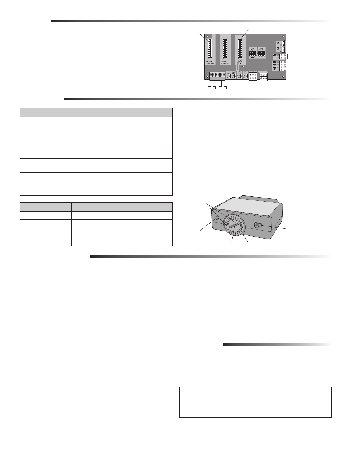
Plug the loop detector into the desired slot (Shadow, Interrupt, or Exit) on the
1
expansion board of the operator. NOTE: If only LOOPDETLM loop detectors are
used, manual frequency adjustments are not required and crosstalk is
eliminated. If a LOOPDETLM is used in combination with other alternate loop
detectors, then manual frequency adjustments may be required.
Insert the twisted wires from the loop into the corresponding terminal (Shadow,
2
Interrupt, or Exit) on the expansion board of the operator. Polarity does not
matter.
OPERATION
BLUE LED WHITE LED EXPLANATION
1 Blink (every 10
seconds)
2 Blinks Rapid Blinks (active fault)
3 Blinks Rapid Blinks (active fault)
4 Blinks Rapid Blinks (active fault) Failed Authentication (see
OFF 2 Blinks Successful Reset
OFF Slow Blinks Loop detector is in TEST or PROG mode
Solid Solid Active Loop
DIAL SETTINGS EXPLANATION
TEST Mode Used to test the loop detector
1-8 Determines the sensitivity setting for the loop detector:
PROG Mode Used to change the frequency of the loop detector
OFF Normal Operation
Open Loop (see TROUBLESHOOTING)
or OFF
Shorted Loop (see TROUBLESHOOTING)
or OFF
TROUBLESHOOTING)
1 is the lowest sensitivity (large vehicle) setting and 8 is the
highest sensitivity (small vehicle). Default setting is 4.
Shadow Slot
Shadow Loop
FREQUENCY
Interrupt Slot Exit Slot
Exit Loop
Interrupt Loop
EXPANSION BOARD
To change the frequency of the loop detector:
Turn the dial to PROG.
1
Press the frequency button to cycle through the 4 frequency settings.
2
NOTE: The blue LED will blink to indicate the current frequency setting.
To reset frequency to factory default, hold the frequency button for 5 seconds.
BOOST SWITCH
The boost switch will increase the sensitivity of the loop detector to detect high profile
vehicles (such as semi trucks).
White LEDs
(located under dial)
Boost Switch
Frequency Button
Blue LED
(located under dial)
Dial
TROUBLESHOOTING
Open or Shorted Loop (2 and 3 Blink errors):
Test the loop detector (refer to TEST THE LOOP DETECTOR section). If the loop
detector passes the test, this indicates the loop detector is working properly and there
is an issue with the loop wiring.
Failed Authentication (4 Blink error):
• Check the wire connecting the expansion board to the main board or
• Unplug the loop detector then plug it back into the same slot (clears all faults and
keeps the current frequency settings, authenticates) or
• Unplug the loop detector. Then unplug the J15 plug on the operator’s control
board and plug it back in after 2-3 seconds. This allows the loop detector to be
plugged into a different slot (clears all faults and keeps the current frequency
settings, authenticates).
To clear a fault:
• Press the reset button on the operator (clears all faults) or
• Unplug the loop detector then plug it back into the same slot.
The loop is making false detections:
• There is crosstalk between the LOOPDETLM and the alternate loop detector or
• Change the frequency or lower the sensitivity setting of the loop detector.
The loop will not activate when a vehicle passes over it:
• Turn the boost switch ON or increase the sensitivity of the loop detector or
• If the blue and white LEDs are solid, indicating an Active Loop, and the operator
does not activate, there could be a fault. Once the loop is inactive, check the LED
codes for a fault (refer to LED table above).
©2011 The Chamberlain Group, Inc.
01-36190D All Rights Reserved
TEST THE LOOP DETECTOR
Turn the dial to TEST. The loop detector will send a signal to the main board
1
simulating a vehicle over the loop.
Exit: If the gate is closed, it will open or if the gate is already open it will
remain open.
Shadow: Active ONLY when the gate is in the open position. If the gate is
open, it will remain open.
Interrupt: If the gate is closing, it will open.
2
Turn the dial back to the desired sensitivity setting.
WARRANTY
ONE YEAR LIMITED WARRANTY
The Chamberlain Group, Inc. warrants to the first retail purchaser of this product that
is free from defect in materials and/or workmanship for a period of 1 year from the
date of purchase.
THIS DEVICE COMPLIES WITH PART 15 OF THE FCC RULES. OPERATION IS SUBJECT TO THE FOLLOWING TWO
CONDITIONS: (1) THIS DEVICE MAY NOT CAUSE HARMFUL INTERFERENCE, AND (2) THIS DEVICE MUST ACCEPT ANY
INTERFERENCE RECEIVED, INCLUDING INTERFERENCE THAT MAY CAUSE UNDESIRED OPERATION.
This Class B digital apparatus complies with Canadian ICES-003.
Cet appareil numérique de la classe B est conforme à la norme NMB-003 du Canada.
www.liftmaster.com
Page 3
HOW TO ORDER
REPAIR PARTS
DEVANCO CANADA
19192 HAY ROAD, UNIT Q
SUMMERSTOWN, ON K0C 2E0
TOLL FREE: 855-931-3334
www.devancocanada.com
WHEN ORDERING REPAIR PARTS
PLEASE SUPPLY THE
FOLLOWING INFORMATION:
3 PART NUMBER
3 DESCRIPTION
3 MODEL NUMBER
 Loading...