

Page 1
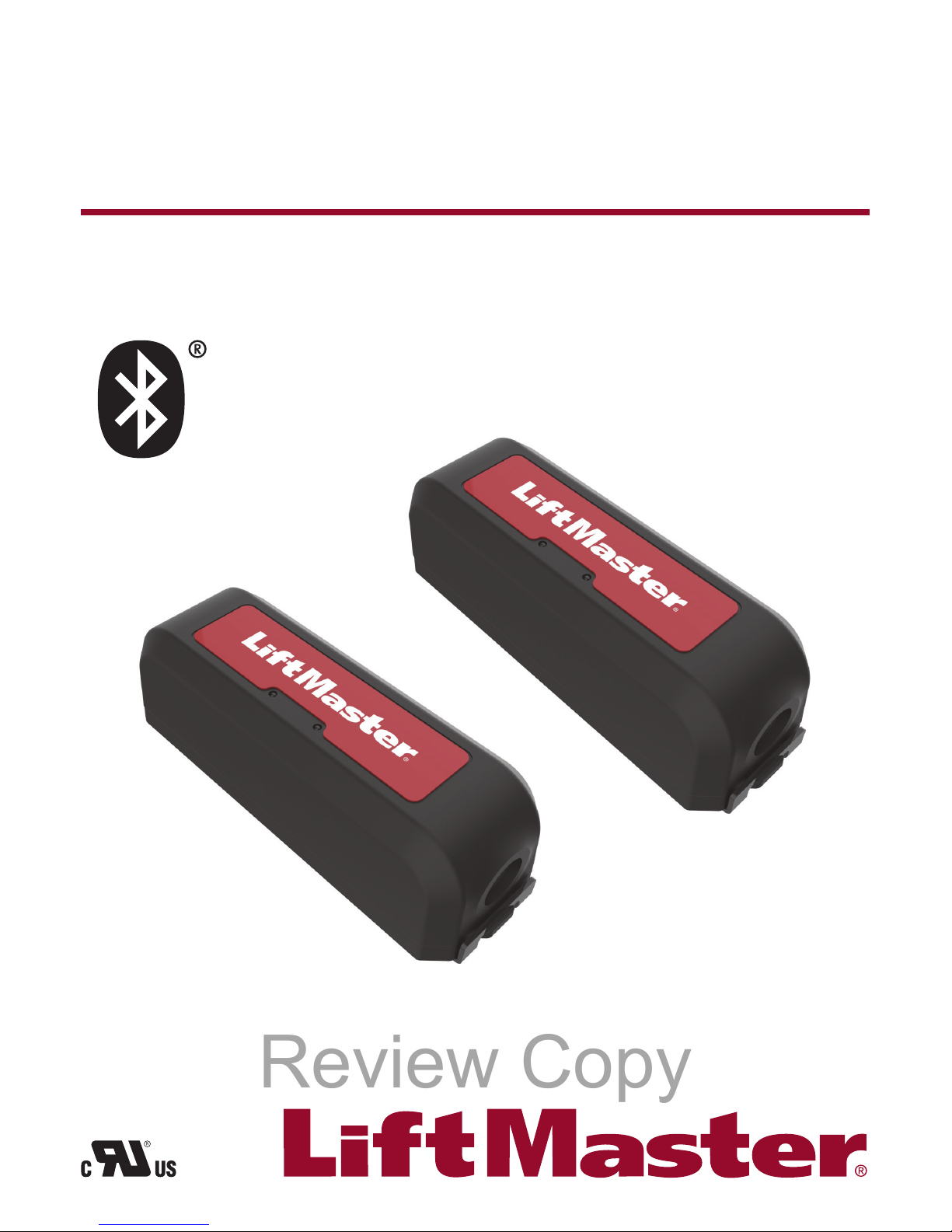
MONITORED WIRELESS EDGE KIT
MONITORED WIRELESS EDGE KIT
MONITORED WIRELESS EDGE KIT
Model/Modèle/Modelo LMWEKITU
Review Copy
Page 2
2
To prevent possible SERIOUS INJURY or DEATH from a closing gate or door:
• Be sure to DISCONNECT ALL POWER to the operator BEFORE installing the wireless edge kit.
• The gate or door MUST be in the fully opened or closed position BEFORE installing the LiftMaster® Monitored
Entrapment Protection device.
• Correctly install and connect the wireless edge kit.
• LiftMaster
®
Monitored Entrapment Protection devices are for use with LiftMaster® UL 325 compliant Gate and
Commercial Door Operators ONLY. Use with ANY other product voids the warranty.
• Monitored external entrapment protection devices MUST be installed per the operator installation manual for each
Entrapment Zone.
To prevent possible SERIOUS INJURY or DEATH from a closing gate or door:
• Be sure to DISCONNECT ALL POWER to the operator BEFORE installing the wireless edge kit.
• The gate or door MUST be in the fully opened or closed position BEFORE installing the LiftMaster® Monitored
Entrapment Protection device.
• Correctly install and connect the wireless edge kit.
• LiftMaster® Monitored Entrapment Protection devices are for use with LiftMaster® UL 325 compliant Gate and
Commercial Door Operators ONLY. Use with ANY other product voids the warranty.
• Monitored external entrapment protection devices MUST be installed per the operator installation manual for each
Entrapment Zone.
To prevent possible SERIOUS INJURY or DEATH from a closing gate or door:
• Be sure to DISCONNECT ALL POWER to the operator BEFORE installing the wireless edge kit.
• The gate or door MUST be in the fully opened or closed position BEFORE installing the LiftMaster® Monitored
Entrapment Protection device.
• Correctly install and connect the wireless edge kit.
• LiftMaster® Monitored Entrapment Protection devices are for use with LiftMaster® UL 325 compliant Gate and
Commercial Door Operators ONLY. Use with ANY other product voids the warranty.
• Monitored external entrapment protection devices MUST be installed per the operator installation manual for each
Entrapment Zone.
ADVERTENCIA
Review Copy
Page 3
3
INTRODUCTION
The LiftMaster® Wireless Edge Kit provides a Bluetooth® connection between a LiftMaster® monitored resistive edge (not included)
and the gate operator. Maximum range is 130 ft. (objects in the path of the signal and location of devices may reduce range). You
can program up to 4 transmitters to the receiver. The kit works with LiftMaster
®
monitored resistive edge sensors ONLY. Contact
closure edge sensors are NOT supported.
For use with LiftMaster
®
gate operators that meet UL 325 requirements. Transmitter and receiver are UL Recognized Components
and meet UL 325 requirements. A monitored safety device MUST be installed in each entrapment zone.
INTRODUCTION
The LiftMaster® Wireless Edge Kit provides a Bluetooth® connection between a LiftMaster® monitored resistive edge (not included)
and the gate operator. Maximum range is 130 ft. (objects in the path of the signal and location of devices may reduce range). You
can program up to 4 transmitters to the receiver. The kit works with LiftMaster
®
monitored resistive edge sensors ONLY. Contact
closure edge sensors are NOT supported.
For use with LiftMaster
®
gate operators that meet UL 325 requirements. Transmitter and receiver are UL Recognized Components
and meet UL 325 requirements. A monitored safety device MUST be installed in each entrapment zone.
INTRODUCCIÓN
The LiftMaster® Wireless Edge Kit provides a Bluetooth® connection between a LiftMaster® monitored resistive edge (not included)
and the gate operator. Maximum range is 130 ft. (objects in the path of the signal and location of devices may reduce range). You
can program up to 4 transmitters to the receiver. The kit works with LiftMaster
®
monitored resistive edge sensors ONLY. Contact
closure edge sensors are NOT supported.
For use with LiftMaster
®
gate operators that meet UL 325 requirements. Transmitter and receiver are UL Recognized Components
and meet UL 325 requirements. A monitored safety device MUST be installed in each entrapment zone.
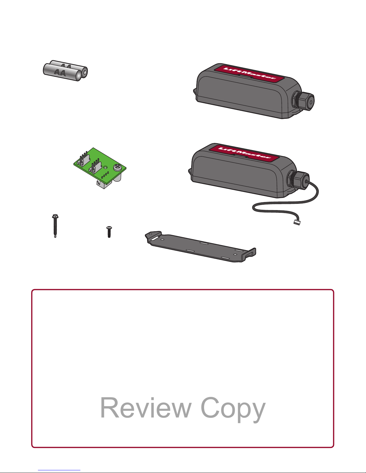
CARTON INVENTORY
INVENTAIRE DE L’EMBALLAGE
CONTENIDO DE LA CAJA
Receiver
Receiver
Receiver
I
2
C Dongle
I
2
C Dongle
I
2
C Dongle
Transmitter
Transmitter
Transmitter
1" Screw (8)
1" Screw (8)
1" Screw (8)
.375" Screw (8)
.375" Screw (8)
.375" Screw (8)
AA Lithium Batteries (2)
Energizer® Ultimate Lithium AA L91 recommended as replacements
AA Lithium Batteries (2)
Energizer® Ultimate Lithium AA L91 recommended as replacements
AA Lithium Batteries (2)
Energizer® Ultimate Lithium AA L91 recommended as replacements
Mounting Bracket (2)
Mounting Bracket (2)
Mounting Bracket (2)
Review Copy
Page 4
4
1
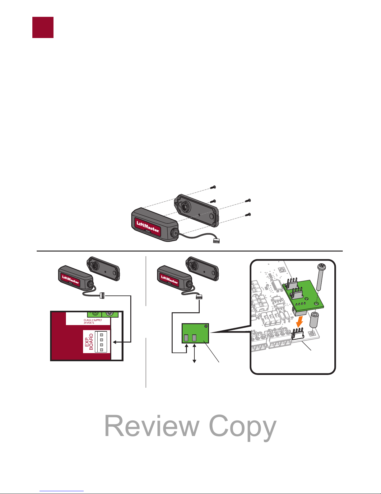
WIRE RECEIVER
1. Find the operator diagram on pages 12-18 to see the mounting location for the receiver and wire routing.
2. Open the receiver housing.
3. Route the wire harness from the receiver to the operator control board. Connect the wire harness to the “EXP. BOARD”
terminal on the control board or to the expansion board (if installed) using the provided I
2
C dongle. Connect the dongle to
the “TO MAIN BOARD” terminal on the expansion board.
The blue power LED will come on.
WIRE RECEIVER
1. Find the operator diagram on pages 12-18 to see the mounting location for the receiver and wire routing.
2. Open the receiver housing.
3. Route the wire harness from the receiver to the operator control board. Connect the wire harness to the “EXP. BOARD”
terminal on the control board or to the expansion board (if installed) using the provided I
2
C dongle. Connect the dongle to
the “TO MAIN BOARD” terminal on the expansion board.
The blue power LED will come on.
WIRE RECEIVER
1. Find the operator diagram on pages 12-18 to see the mounting location for the receiver and wire routing.
2. Open the receiver housing.
3. Route the wire harness from the receiver to the operator control board. Connect the wire harness to the “EXP. BOARD”
terminal on the control board or to the expansion board (if installed) using the provided I
2
C dongle. Connect the dongle to
the “TO MAIN BOARD” terminal on the expansion board.
The blue power LED will come on.
Illustrations in manual are for reference only, your application may look different
Les illustrations dans le manuel sont fournies à titre de référence uniquement; votre application peut avoir une autre apparence.
Las ilustraciones del manual se ofrecen únicamente como referencia, su instalación podría ser diferente.
Expansion Board
Tableau d’extension
Tarjeta de expansión
2
3
Control Board
Tableau de commande
Tarjeta de control
OR
OU
O
To Main Control Board
To Main Control Board
To Main Control Board
I2C Dongle
I
2
C Dongle
I
2
C Dongle
Review Copy
Page 5
5
2
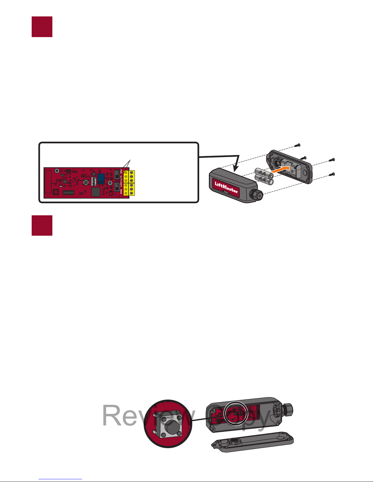
INSTALL TRANSMITTER BATTERIES AND SET EDGE DIRECTION
1. Open the transmitter housing.
2. Install the batteries.
3. Decide the direction (open or closed) the edge will be installed. Set “OPEN/CLOSE” DIP switch to match the direction of
the edge protection.
INSTALL TRANSMITTER BATTERIES AND SET EDGE DIRECTION
1. Open the transmitter housing.
2. Install the batteries.
3. Decide the direction (open or closed) the edge will be installed. Set “OPEN/CLOSE” DIP switch to match the direction of
the edge protection.
INSTALL TRANSMITTER BATTERIES AND SET EDGE DIRECTION
1. Open the transmitter housing.
2. Install the batteries.
3. Decide the direction (open or closed) the edge will be installed. Set “OPEN/CLOSE” DIP switch to match the direction of
the edge protection.
PROGRAMMING
The receiver can learn up to 4 transmitters.
1. Press the learn button on the RECEIVER board. The red LED will come on and the operator control board will beep once
to indicate programming mode. NOTE: Press the learn button again to exit programming mode.
2. Press the learn button on the TRANSMITTER to be learned. The red LED on the RECEIVER will blink 4 times. Press the
learn button on the next TRANSMITTER to be learned. NOTE: Learn mode times out after 60 seconds if no transmitters
are added or the capacity is reached. After each transmitter is learned there will be an additional 60 seconds to complete
programming.
PROGRAMMATION
The receiver can learn up to 4 transmitters.
1. Press the learn button on the RECEIVER board. The red LED will come on and the operator control board will beep once
to indicate programming mode. NOTE: Press the learn button again to exit programming mode.
2. Press the learn button on the TRANSMITTER to be learned. The red LED on the RECEIVER will blink 4 times. Press the
learn button on the next TRANSMITTER to be learned. NOTE: Learn mode times out after 60 seconds if no transmitters
are added or the capacity is reached. After each transmitter is learned there will be an additional 60 seconds to complete
programming.
PROGRAMACIÓN
The receiver can learn up to 4 transmitters.
1. Press the learn button on the RECEIVER board. The red LED will come on and the operator control board will beep once
to indicate programming mode. NOTE: Press the learn button again to exit programming mode.
2. Press the learn button on the TRANSMITTER to be learned. The red LED on the RECEIVER will blink 4 times. Press the
learn button on the next TRANSMITTER to be learned. NOTE: Learn mode times out after 60 seconds if no transmitters
are added or the capacity is reached. After each transmitter is learned there will be an additional 60 seconds to complete
programming.
3
Learn Button
Bouton Apprendre
Botón de Programación
OPEN/CLOSE Dip Switches
OPEN/CLOSE Dip Switches
OPEN/CLOSE Dip Switches
Review Copy
Page 6
6
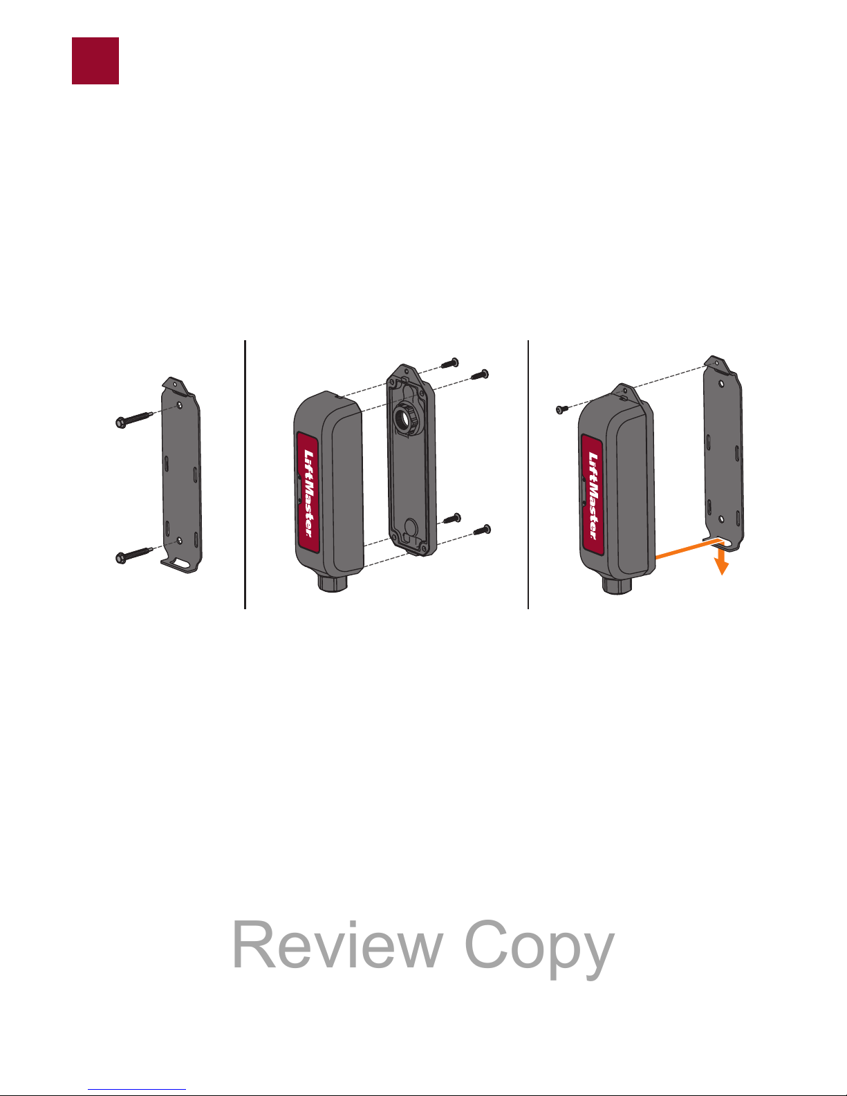
MOUNT THE RECEIVER
1. Find the operator diagram on pages 12-18 to see the mounting location for the receiver.
2. Attach the mounting bracket to the gate operator.
3. Reattach the receiver housing.
4. Snap the receiver onto the mounting bracket and secure with screw provided.
MOUNT THE RECEIVER
1. Find the operator diagram on pages 12-18 to see the mounting location for the receiver.
2. Attach the mounting bracket to the gate operator.
3. Reattach the receiver housing.
4. Snap the receiver onto the mounting bracket and secure with screw provided.
MOUNT THE RECEIVER
1. Find the operator diagram on pages 12-18 to see the mounting location for the receiver.
2. Attach the mounting bracket to the gate operator.
3. Reattach the receiver housing.
4. Snap the receiver onto the mounting bracket and secure with screw provided.
4
23 4
Review Copy
Page 7
7
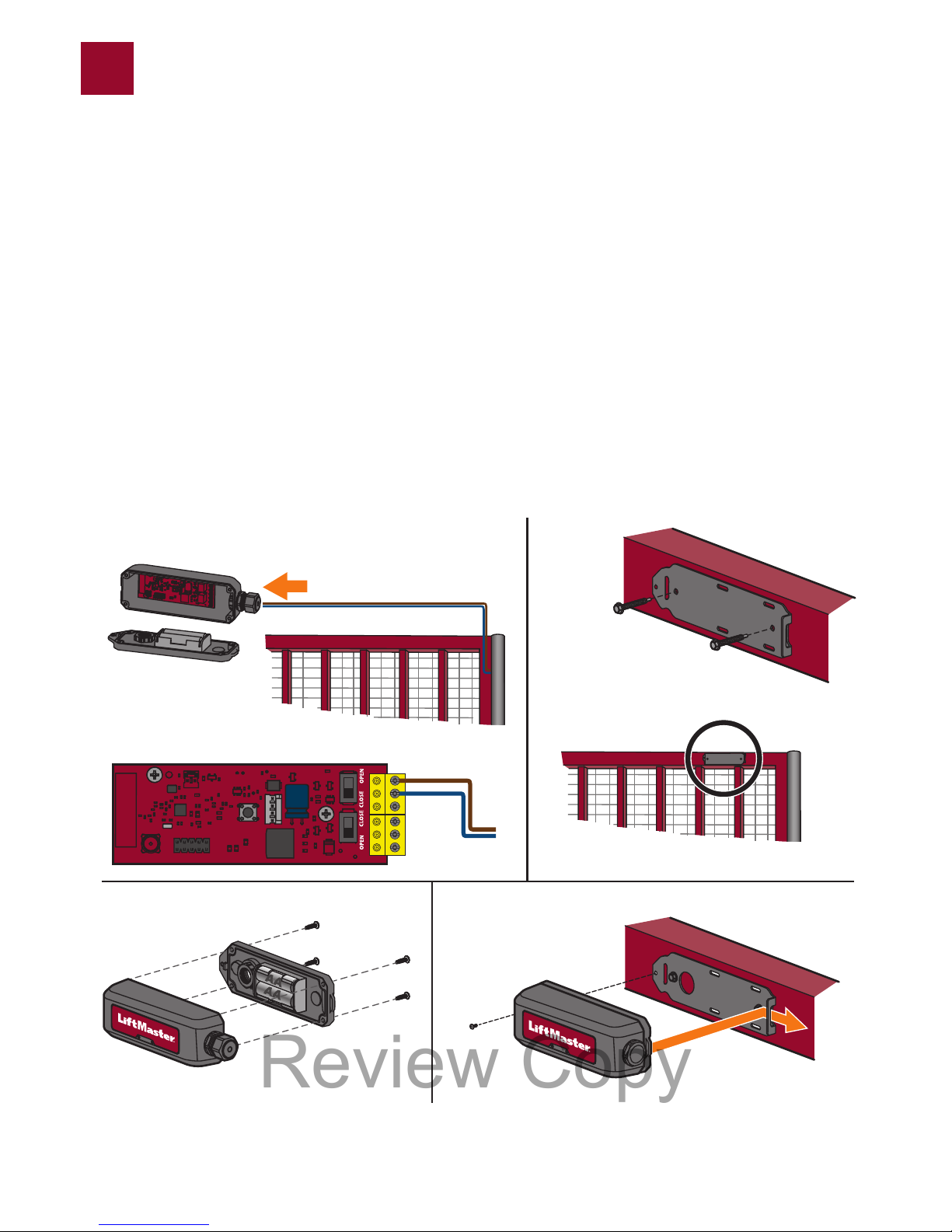
WIRE AND MOUNT THE TRANSMITTER(S)
NOTE: The transmitter can be wired to 1 or 2 edge sensors.
1. Route the wires from the edge sensor into the transmitter. Connect the wires to the terminal blocks (polarity is NOT
important).
2. Attach the mounting bracket to the gate using the screws provided. If installing on a round surface, use zip ties (not
provided).
3. Reattach the transmitter housing.
4. Snap the transmitters onto the mounting bracket and secure with the screw provided.
WIRE AND MOUNT THE TRANSMITTER(S)
NOTE: The transmitter can be wired to 1 or 2 edge sensors.
1. Route the wires from the edge sensor into the transmitter. Connect the wires to the terminal blocks (polarity is NOT
important).
2. Attach the mounting bracket to the gate using the screws provided. If installing on a round surface, use zip ties (not
provided).
3. Reattach the transmitter housing.
4. Snap the transmitters onto the mounting bracket and secure with the screw provided.
WIRE AND MOUNT THE TRANSMITTER(S)
NOTE: The transmitter can be wired to 1 or 2 edge sensors.
1. Route the wires from the edge sensor into the transmitter. Connect the wires to the terminal blocks (polarity is NOT
important).
2. Attach the mounting bracket to the gate using the screws provided. If installing on a round surface, use zip ties (not
provided).
3. Reattach the transmitter housing.
4. Snap the transmitters onto the mounting bracket and secure with the screw provided.
5
12
34
Review Copy
Page 8
8
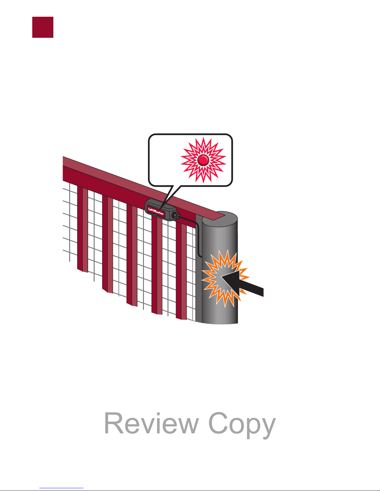
TEST
Apply pressure to edge. The red LED on the TRANSMITTER and the corresponding open or close edge LED on the gate
operator control board will flash. If the TRANSMITTER LED does not flash, check the transmitter and edge sensor for proper
installation and wiring.
TEST
Apply pressure to edge. The red LED on the TRANSMITTER and the corresponding open or close edge LED on the gate
operator control board will flash. If the TRANSMITTER LED does not flash, check the transmitter and edge sensor for proper
installation and wiring.
TEST
Apply pressure to edge. The red LED on the TRANSMITTER and the corresponding open or close edge LED on the gate
operator control board will flash. If the TRANSMITTER LED does not flash, check the transmitter and edge sensor for proper
installation and wiring.
Status LED
Status LED
Status LED
6
Review Copy
Page 9
9
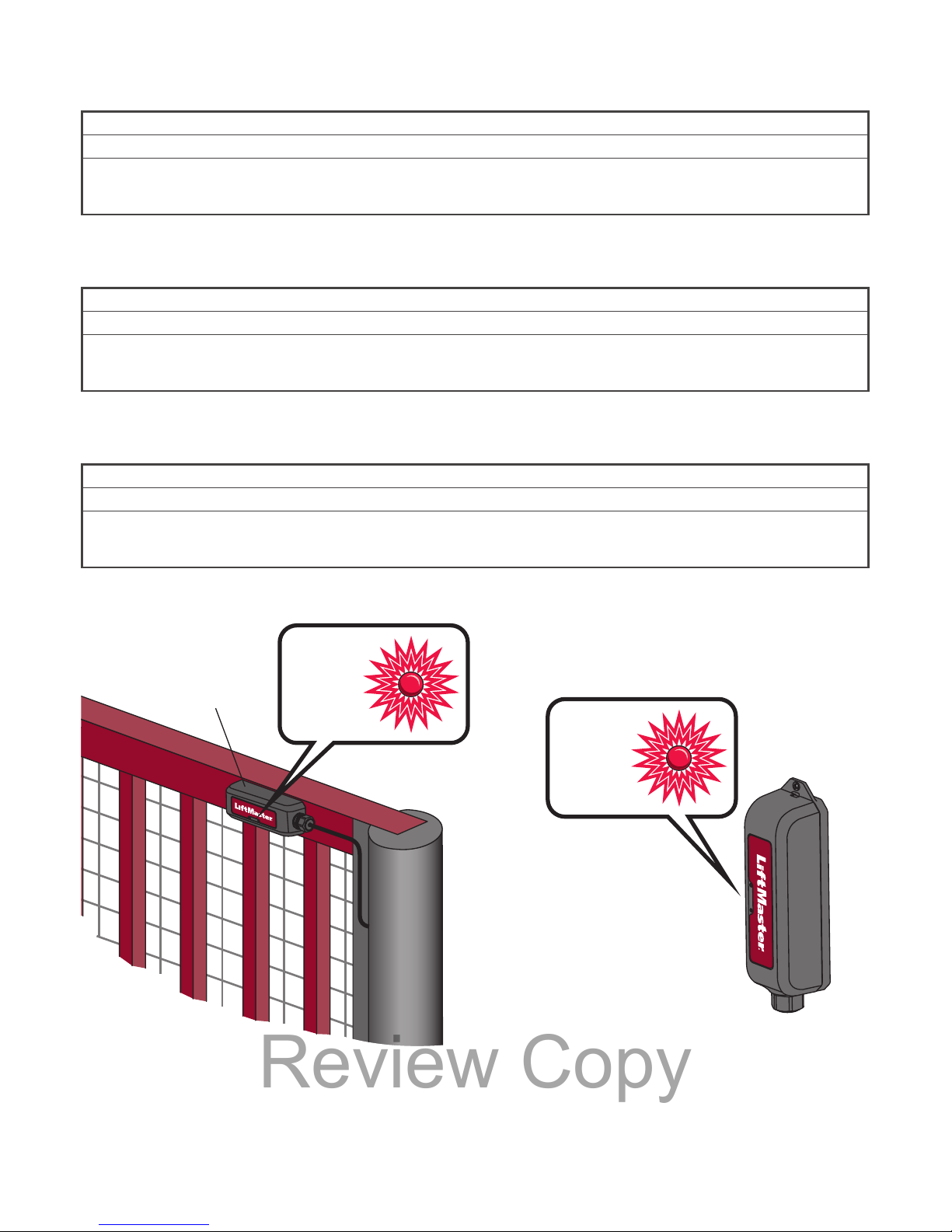
BATTERY STATUS
During normal operation, the red status LEDs on the transmitter(s) and receiver flash to indicate the battery status.
NOTE: The receiver LED corresponds to the lowest battery level of all transmitters.
1 Flash Battery is fine.
2 Flashes Battery is low; the operator will beep twice.
3 Flashes Battery is critically low; the operator will not function until the battery is replaced. The operator will either open
automatically (fail-safe) or latch at close (fail-secure) based on the operator setting (see the gate operator manual for
more information).
BATTERY STATUS
During normal operation, the red status LEDs on the transmitter(s) and receiver flash to indicate the battery status.
NOTE: The receiver LED corresponds to the lowest battery level of all transmitters.
1 Flash Battery is fine.
2 Flashes Battery is low; the operator will beep twice.
3 Flashes Battery is critically low; the operator will not function until the battery is replaced. The operator will either open
automatically (fail-safe) or latch at close (fail-secure) based on the operator setting (see the gate operator manual for
more information).
BATTERY STATUS
During normal operation, the red status LEDs on the transmitter(s) and receiver flash to indicate the battery status.
NOTE: The receiver LED corresponds to the lowest battery level of all transmitters.
1 Flash Battery is fine.
2 Flashes Battery is low; the operator will beep twice.
3 Flashes Battery is critically low; the operator will not function until the battery is replaced. The operator will either open
automatically (fail-safe) or latch at close (fail-secure) based on the operator setting (see the gate operator manual for
more information).
Receiver
Receiver
Receiver
Transmitter
Transmitter
Transmitter
Status LED
Status LED
Status LED
Status LED
Status LED
Status LED
Review Copy
Page 10
10
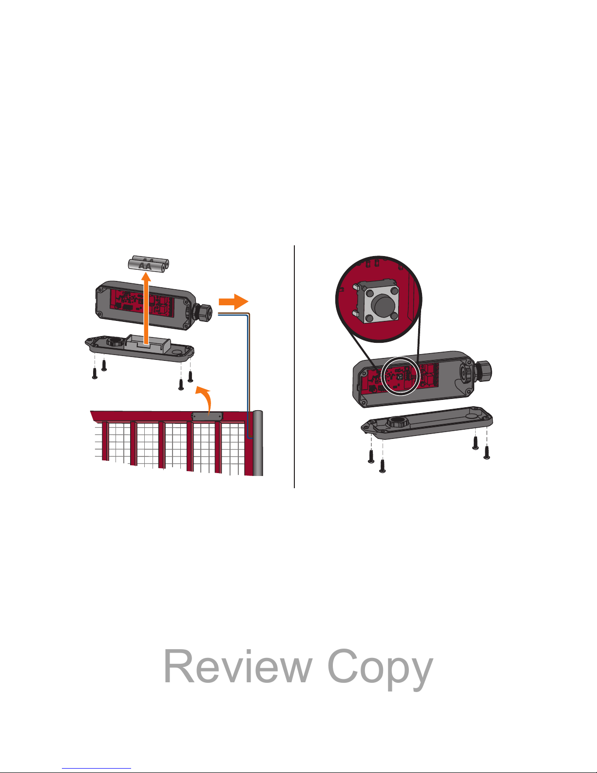
REMOVE A TRANSMITTER
1. Disconnect the edge sensor wires from the TRANSMITTER.
2. Remove the batteries from the TRANSMITTER.
3. Press and hold the RECEIVER learn button until the red status LED begins to flash (about 3 seconds) then release. The receiver will
remove disconnected transmitters from memory and return to normal operation after 60 seconds or when the user presses the learn
button again.
REMOVE A TRANSMITTER
1. Disconnect the edge sensor wires from the TRANSMITTER.
2. Remove the batteries from the TRANSMITTER.
3. Press and hold the RECEIVER learn button until the red status LED begins to flash (about 3 seconds) then release. The receiver will
remove disconnected transmitters from memory and return to normal operation after 60 seconds or when the user presses the learn
button again.
REMOVE A TRANSMITTER
1. Disconnect the edge sensor wires from the TRANSMITTER.
2. Remove the batteries from the TRANSMITTER.
3. Press and hold the RECEIVER learn button until the red status LED begins to flash (about 3 seconds) then release. The receiver will
remove disconnected transmitters from memory and return to normal operation after 60 seconds or when the user presses the learn
button again.
ERASE ALL TRANSMITTERS FROM MEMORY
Press and hold the RECEIVER learn button until the red status LED begins to flash. Hold the learn button until the LED turns off (about
10 seconds) then release. The gate operator will beep for 5 seconds to confirm all transmitters are erased.
ERASE ALL TRANSMITTERS FROM MEMORY
Press and hold the RECEIVER learn button until the red status LED begins to flash then turns off (about 10 seconds) then release. The
operator will beep for 5 seconds to confirm all transmitters are erased.
ERASE ALL TRANSMITTERS FROM MEMORY
Press and hold the RECEIVER learn button until the red status LED begins to flash then turns off (about 10 seconds) then release. The
operator will beep for 5 seconds to confirm all transmitters are erased.
Receiver
Receiver
Receiver
Transmitter
Transmitter
Transmitter
Learn Button
Bouton Apprendre
Botón de Programación
1-2 3
Review Copy
Page 11
11
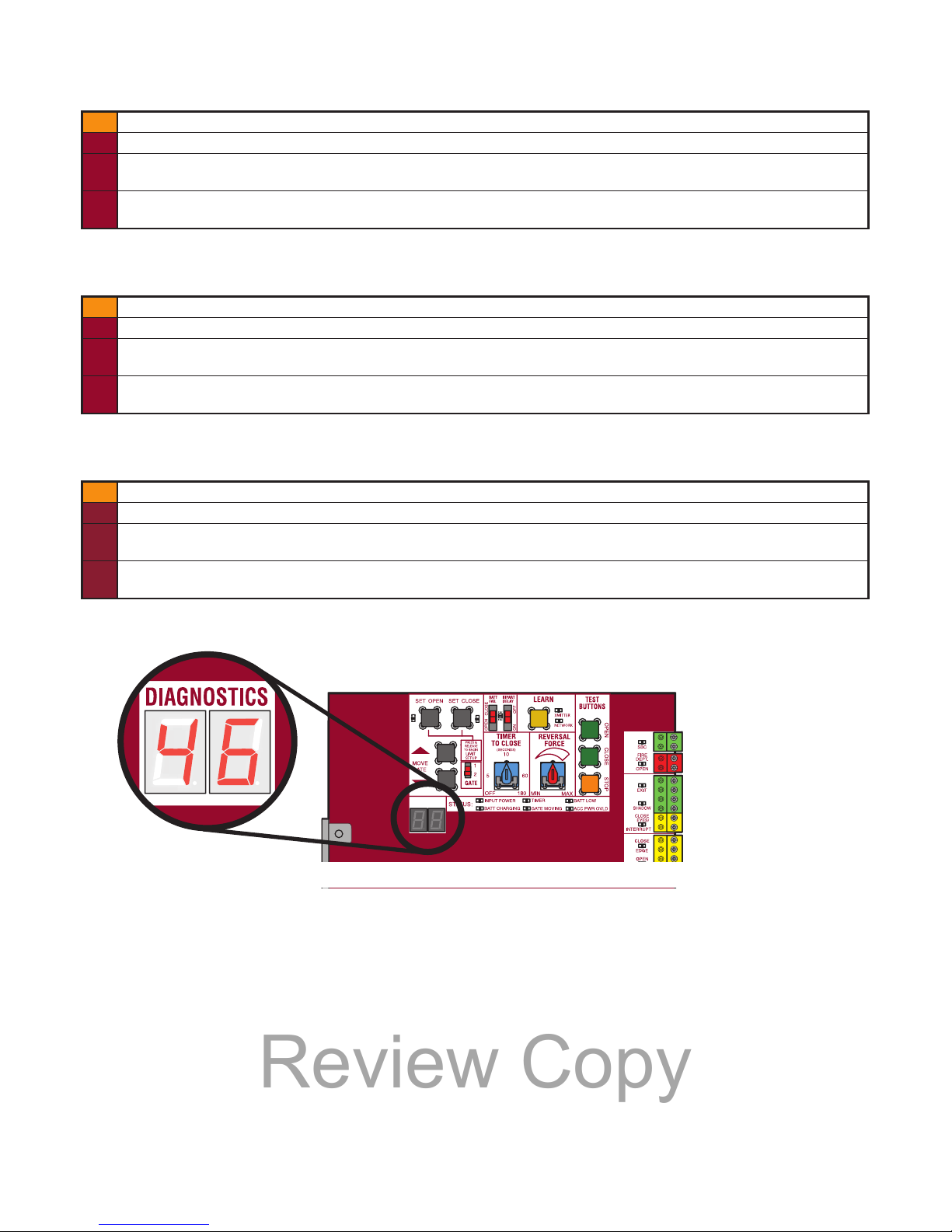
TROUBLESHOOTING
The diagnostic display on the operator control board will display an error code to indicate a problem. See the gate operator manual for
instructions to display error codes.
46 Wireless edge battery low Replace batteries in wireless edge.
67 Wireless edge triggered more than 3 minutes Check wired input for wiring issue or obstruction.
68 Wireless edge loss of monitoring Check wireless edge inputs. Check for connection between receiver
and main board/expansion board.
69 Wireless edge triggered IF an obstruction occurred, no action required. If an obstruction did
NOT occur, check inputs and wiring.
DÉPANNAGE
The diagnostic display on the operator control board will display an error code to indicate a problem. See the gate operator manual for
instructions to display error codes.
46 Pile faible du chant sans fil Remplacer les piles du chant sans fil.
67 Chant sans fil déclenché pendant plus de 3 minutes Vérifi er l’entrée câblée pour tout problème de câblage ouobstruction.
68 Perte de surveillance du chant sans fil Vérifi er les entrées du chant sans fil. Check for connection between
receiver and main board/expansion board.
69 Chant sans fil déclenché Si une obstruction s’est produite, aucune action n’est requise. Si une
obstruction ne s’est pas produite, vérifi er les entrées et le câblage.
RESOLUCIÓN DE PROBLEMAS
The diagnostic display on the operator control board will display an error code to indicate a problem. See the gate operator manual for
instructions to display error codes.
46 Wireless edge battery low Replace batteries in wireless edge.
67 Wireless edge triggered more than 3 minutes Check wired input for wiring issue or obstruction.
68 Wireless edge loss of monitoring Check wireless edge inputs. Check for connection between receiver
and main board/expansion board.
69 Wireless edge triggered IF an obstruction occurred, no action required. If an obstruction did
NOT occur, check inputs and wiring.
Control Board
Tableau de commande
T
arjeta de control
DIAGNOSTICS
Review Copy
Page 12
12
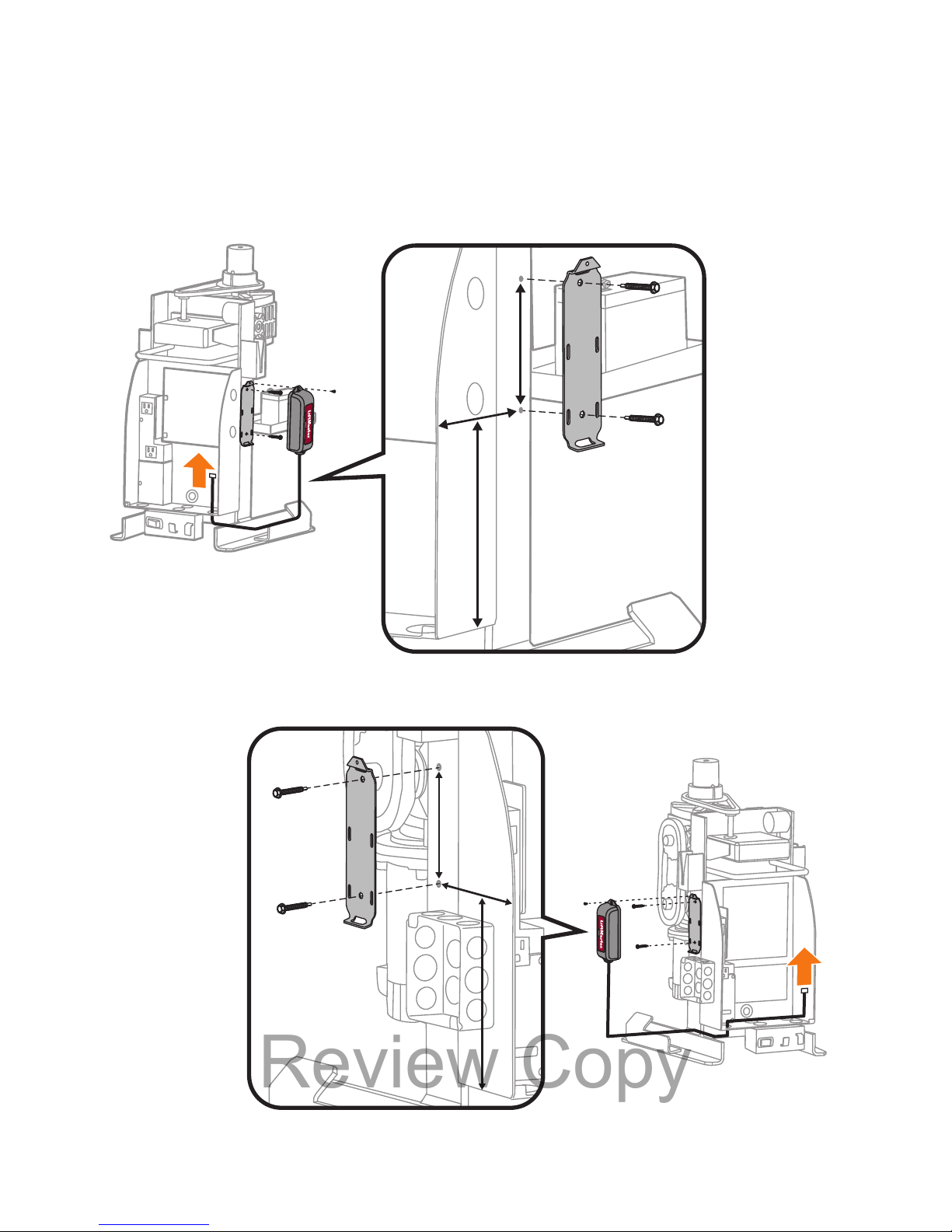
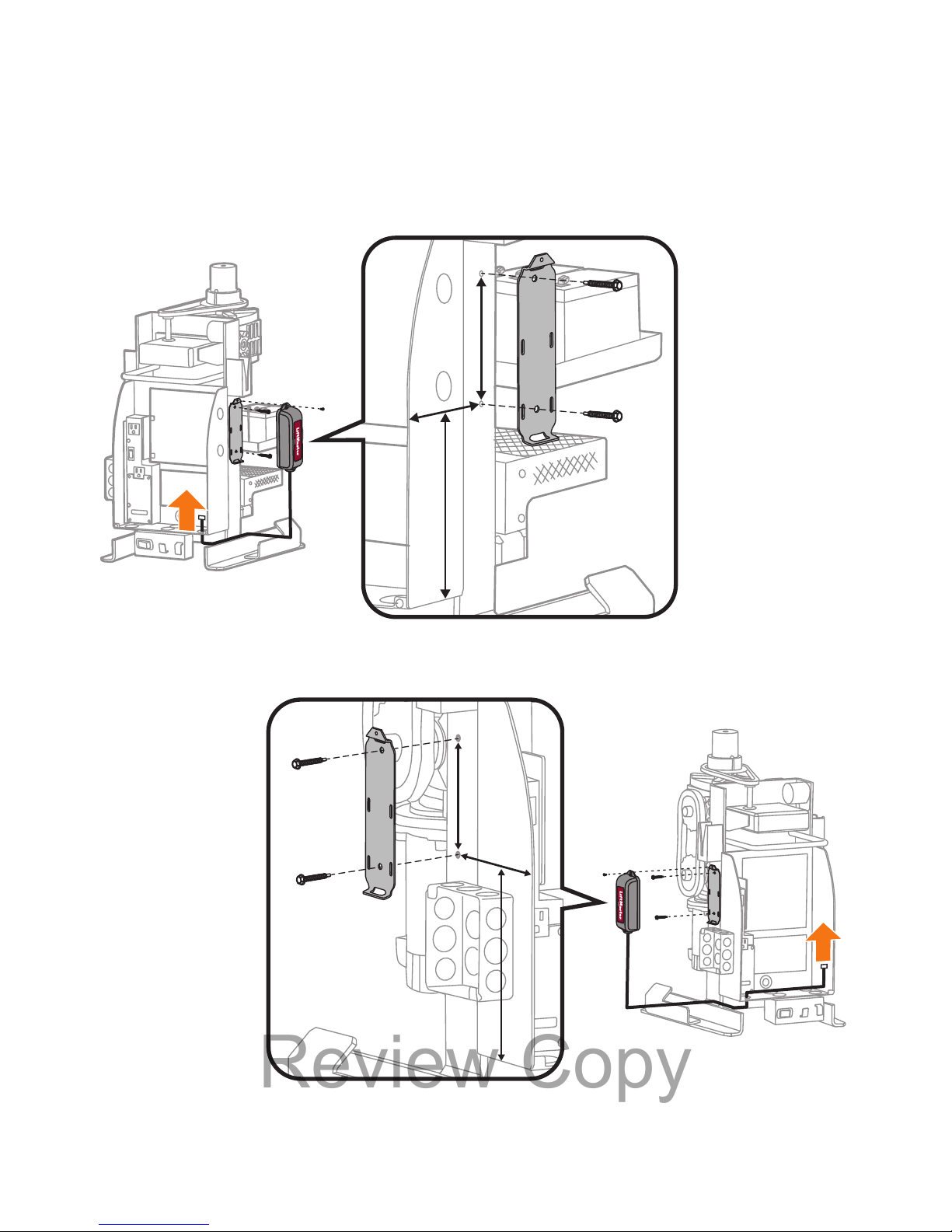
MODEL RSW12U - RECEIVER MOUNTING LOCATION
Mount the bracket on the side facing the gate.
MODEL RSW12U - RECEIVER MOUNTING LOCATION
Mount the bracket on the side facing the gate.
MODEL RSW12U - RECEIVER MOUNTING LOCATION
Mount the bracket on the side facing the gate.
RSW12U
B
4-7/16" (11.27 cm)
A
7-1/2" (19.05 cm)
C
6-1/8" (15.55 cm)
C
B
A
RSW12U
B
4-7/16" (11.27 cm)
A
7-1/2" (19.05 cm)
C
6-1/8" (15.55 cm)
C
B
A
Review Copy
Page 13
13
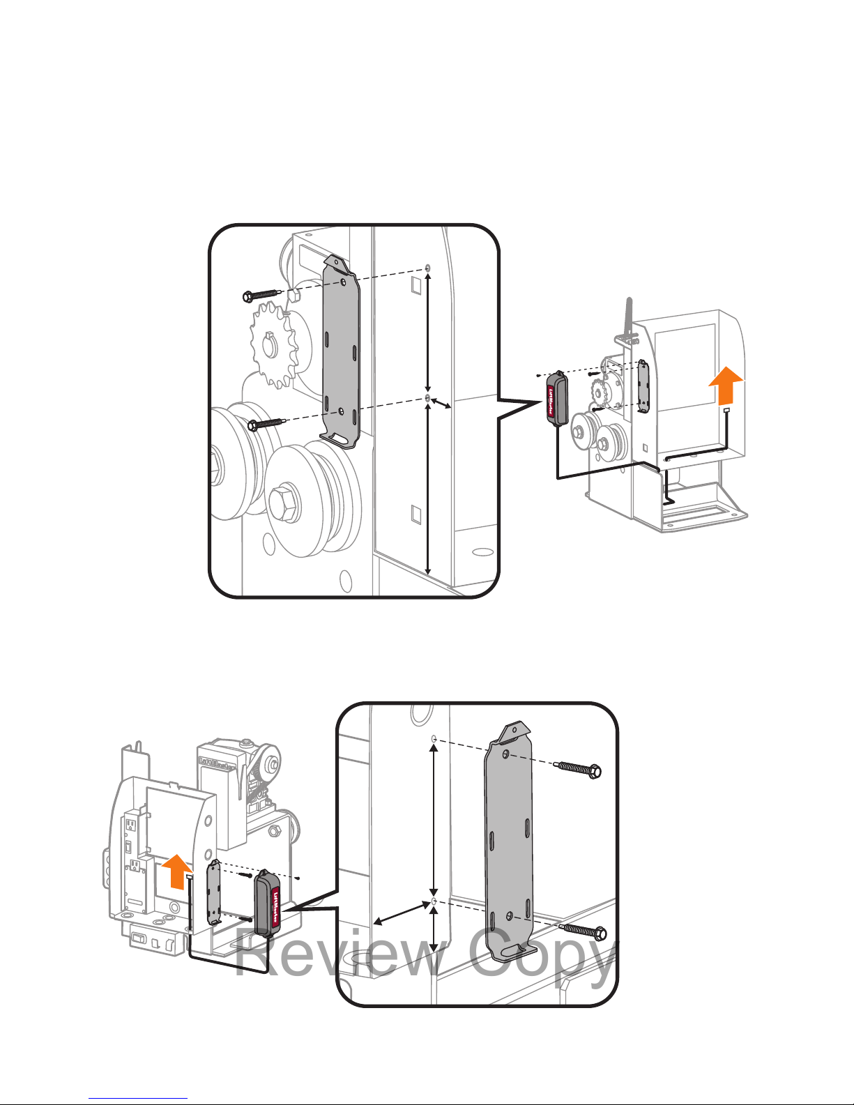
MODEL CSW24U - RECEIVER MOUNTING LOCATION
Mount the bracket on the side facing the gate.
MODÈLE CSW24U - RECEIVER MOUNTING LOCATION
Mount the bracket on the side facing the gate.
MODELO CSW24U - RECEIVER MOUNTING LOCATION
Mount the bracket on the side facing the gate.
CSW24U
CSW24U
B
4-7/16" (11.27 cm)
A
7-1/2" (19.05 cm)
C
6-1/8" (15.55 cm)
B
4-7/16" (11.27 cm)
A
7-1/2" (19.05 cm)
C
6-1/8" (15.55 cm)
C
B
A
C
B
A
Review Copy
Page 14
14
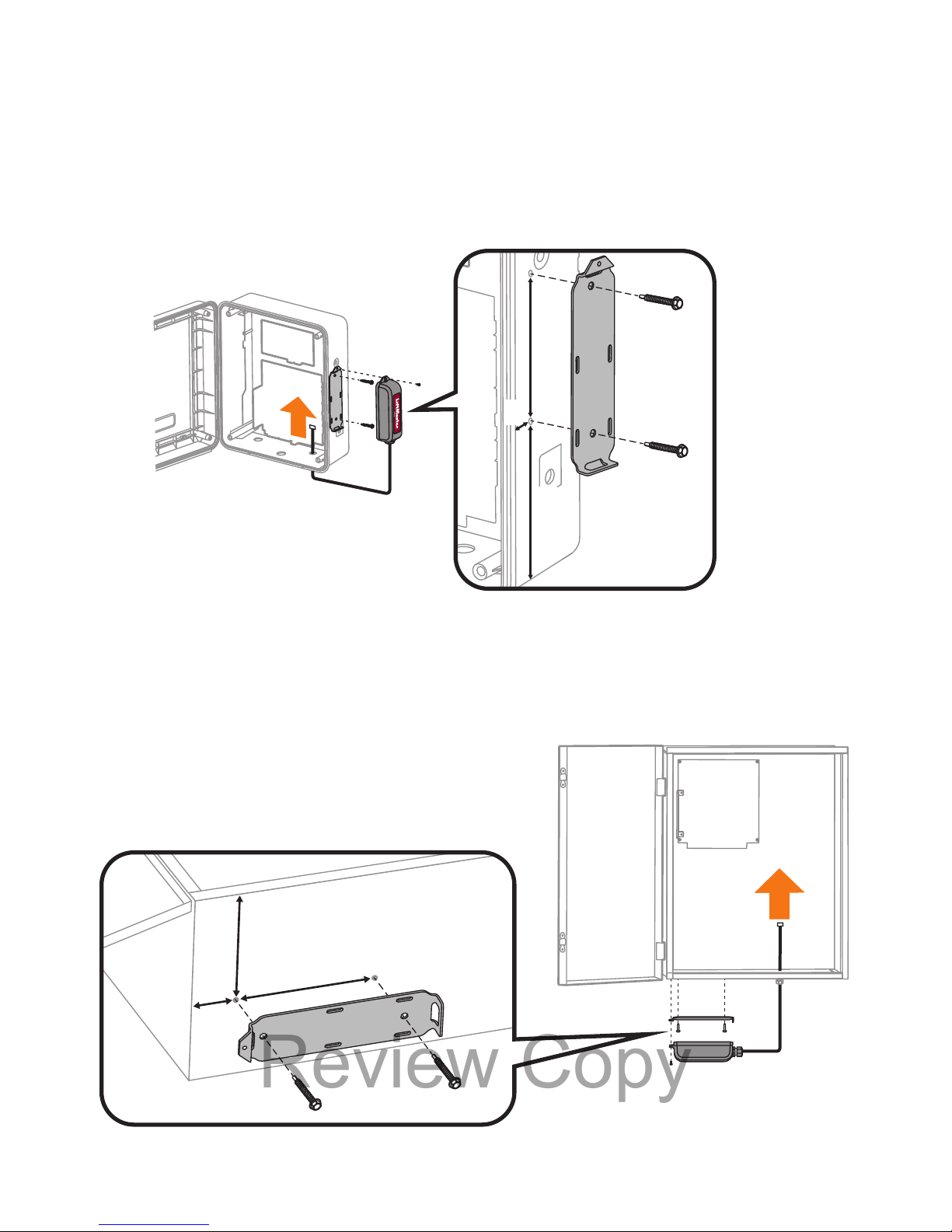
MODELS RSL12U AND CSL24U - RECEIVER MOUNTING LOCATION
MODÈLES RSL12U ET CSL24U - RECEIVER MOUNTING LOCATION
MODELOS RSL12U Y CSL24U - RECEIVER MOUNTING LOCATION
CSL24U
B
4-7/16" (11.27 cm)
A
1-1/2" (3.81 cm)
C
3-3/16" (8.09 cm)
C
B
A
RSL12U
B
4-7/16" (11.27 cm)
A
5" (12.7 cm)
C
1-3/4" (4.44 cm)
C
B
A
Review Copy
Page 15
15
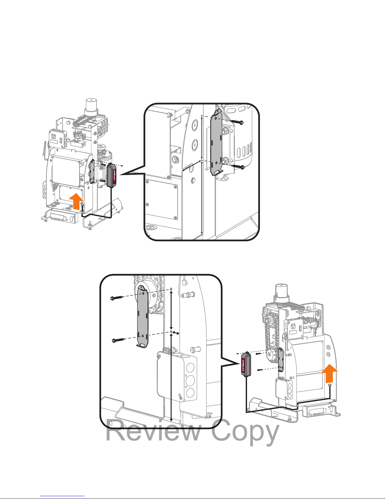
MODELS LA400, LA412, AND LA500 - RECEIVER MOUNTING LOCATION
MODÈLES LA400U, LA412, ET LA500 - RECEIVER MOUNTING LOCATION
MODELOS LA400U, LA412, Y LA500 - RECEIVER MOUNTING LOCATION
STANDARD CONTROL BOX
BOÎTER DE CONTRÔLE STANDARD
CAJA DE CONTROL ESTÁNDAR
B
4-7/16" (11.27 cm)
A
5-1/8" (13.01 cm))
C
1" (2.54 cm)
B
C
A
B
4-7/16" (11.27 cm)C3-1/2" (8.89 cm)
A
1" (2.54 cm)
C
B
A
STANDARD CONTROL BOX
GRAND BOÎTER DE CONTRÔLE EN MÉTAL
CAJA DE CONTROL METÁLICA GRANDE
Review Copy
Page 16
16
CSW200U
B
4-7/16" (11.27 cm)
A
8" (20.32 cm)
C
3-3/4" (9.52 cm)
C
B
A
CSW200U
B
4-7/16" (11.27 cm)
A
9" (22.86 cm)
C
1-1/2" (3.81 cm)
C
B
A
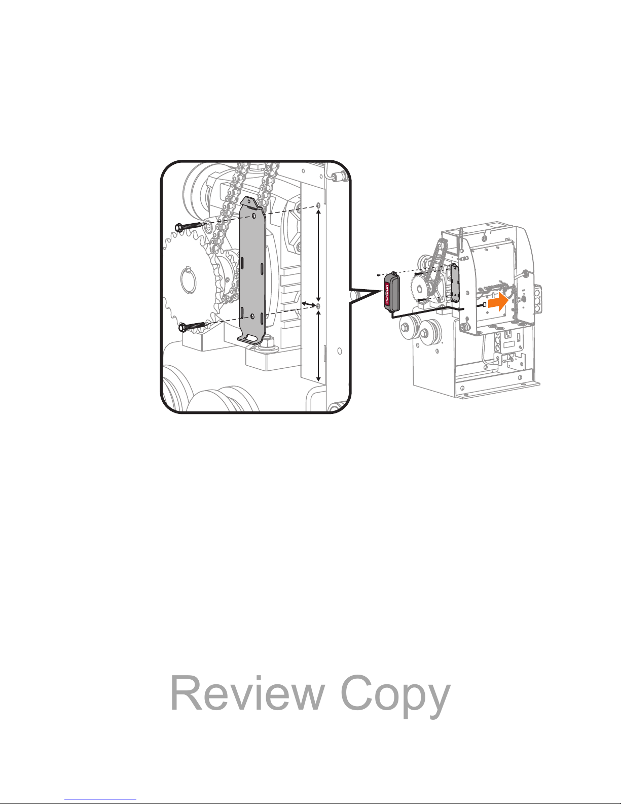
MODEL CSW200U - RECEIVER MOUNTING LOCATION
Mount the bracket on the side facing the gate.
MODÈLE CSW200U - RECEIVER MOUNTING LOCATION
Mount the bracket on the side facing the gate.
MODELO CSW200U - RECEIVER MOUNTING LOCATION
Mount the bracket on the side facing the gate.
Review Copy
Page 17
17
SL3000
B
4-7/16" (11.27 cm)
A
3-1/4" (8.25 cm)
C
1" (2.54 cm)
C
B
A
MODEL SL3000U - RECEIVER MOUNTING LOCATION
Mount the bracket on the side facing the gate.
MODÈLE SL3000U - RECEIVER MOUNTING LOCATION
Mount the bracket on the side facing the gate.
MODELO SL3000U - RECEIVER MOUNTING LOCATION
Mount the bracket on the side facing the gate.
Review Copy
Page 18
18
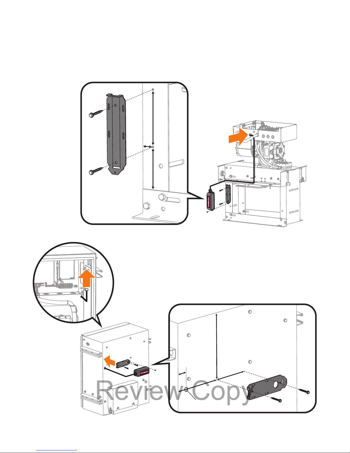
MODELS SL585 AND SL595 - RECEIVER MOUNTING LOCATION
MODÈLES SL585 AND SL595 - RECEIVER MOUNTING LOCATION
MODELOS SL585 AND SL595 - RECEIVER MOUNTING LOCATION
SL595
B
4-7/16" (11.27 cm)
A
6" (15.24 cm)
C
11-3/4" (29.84 cm)
.875" (2.22 cm)
D
1" (2.54 cm)
B
C
D
A
SL585
B
4-7/16" (11.27 cm)
A
4-1/16" (10.3 cm)
C
1" (2.54 cm)
C
B
A
Review Copy
Page 19
19
WARRANTY
LiftMaster® warrants to the first consumer purchaser of this product that it is free from defect in materials and/or workmanship for
a period of 2 years from the date of purchase.
GARANTIE
LiftMaster® garantit à l’acheteur initial de ce produit que celui-ci est exempt de tout défaut matériel ou de fabrication pendant une
période de deux ans suivant la date d’achat.
GARANTÍA
LiftMaster® garantiza al primer comprador minorista de este producto, que el mismo está libre de defectos de materiales y de mano
de obra por un período de dos años a partir de la fecha de compra.
NOTICE: This device complies with part 15 of the FCC rules and Industry Canada (IC) licence-exempt RSS standard(s). Operation is subject to the following
two conditions: (1) this device may not cause harmful interference, and (2) this device must accept any interference received, including interference that
may cause undesired operation.
Any changes or modifications not expressly approved by the party responsible for compliance could void the user’s authority to operate the equipment.
This Class B digital apparatus complies with Canadian ICES-003.
This device must be installed in a way where a minimum 8" (20cm) distance is maintained between users/bystanders and device.
This device has been tested and found to comply with the limits for a Class B digital device, pursuant to part 15 of the FCC rules. These limits are designed
to provide reasonable protection against harmful interference in a residential installation. This equipment generates, uses and can radiate radio frequency
energy and, if not installed and used in accordance with the instructions, may cause harmful interference to radio communications. However, there is no
guarantee that interference will not occur in a particular installation. If this equipment does cause harmful interference to radio or television reception,
which can be determined by turning the equipment off and on, the user is encouraged to try to correct the interference by one or more of the following
measures:
- Reorient or relocate the receiving antenna.
- Increase the separation between the equipment and receiver.
- Connect the equipment into an outlet on a circuit different from that to which the receiver is connected.
- Consult the dealer or an experienced radio/TV technician for help.
AVIS : Ce dispositif est conforme à la partie 15 des règles de la FCC et des normes RSS exemptées de licence d’Industrie Canada (IC). L’utilisation est
assujettie aux deux conditions ci-après : (1) ce dispositif ne doit pas causer d’interférences nuisibles, et (2) ce dispositif doit accepter toute interférence
reçue, y compris une interférence pouvant causer un fonctionnement indésirable.
Tout changement ou toute modification non expressément approuvés par la partie responsable de la conformité pourrait annuler l’autorité de l’utilisateur
d’utiliser l’équipement.
Cet appareil numérique de classe B est conforme à la norme ICES-003 du Canada.
This device must be installed in a way where a minimum 8” (20cm) distance is maintained between users/bystanders and device.
Ce dispositif a été mis à l’essai et déclaré conforme aux limites établies pour les dispositifs numériques de classe B, conformément à l’article 15 des règles
de la FCC. Cette conformité a pour but de fournir une protection raisonnable contre les interférences nuisibles dans une installation résidentielle. Cet
équipement génère, utilise et peut émettre des fréquences radio et, s’il n’est pas installé et utilisé conformément aux instructions, causer des interférences
nuisibles aux communications radio. Cependant, il n’existe aucune garantie que des interférences ne se produiront pas dans une installation particulière. Si
cet équipement provoque des interférences nuisibles à la réception d’une diffusion sonore ou visuelle, ce qui peut être déterminé en l’allumant et en
l’éteignant, l’utilisateur est invité à essayer de résoudre ce problème en prenant une ou plusieurs des mesures suivantes :
- Réorienter ou déplacer antenne de réception.
- Augmenter la distance entre l’équipement et le récepteur.
- Brancher l’appareil à une prise sur un circuit différent de celui du récepteur.
- Pour obtenir de l’aide, consulter le détaillant ou un radiotechnicien expérimenté.
AVISO: Este dispositivo cumple con la Parte 15 de las normas FCC y las normas RSS con excepción de licencia de Industry Canada (IC) de Canadá. El uso
está sujeto a las siguientes condiciones: (1) Este dispositivo no debe causar interferencia perjudicial, y (2) este dispositivo debe poder recibir interferencia,
incluso interferencia que pueda afectar su funcionamiento.
Todo cambio o toda modificación no expresamente aprobada por la parte responsable del cumplimiento podría anular el derecho de usar el equipo.
Este aparato digital de Clase B cumple con las normas canadienses ICES-003
This device must be installed in a way where a minimum 8” (20cm) distance is maintained between users/bystanders and device.
Este dispositivo ha sido probado y cumple con los límites establecidos para un dispositivo digital de Clase B según la Parte 15 de las Normas de FCC de
EE.UU. Estos límites tienen por objeto brindar un grado razonable de protección contra interferencias molestas en una instalación residencial. Este equipo
genera, usa y puede emitir energía de radiofrecuencia. Si no se instala y utiliza de acuerdo con las instrucciones podrá causar interferencia con
comunicaciones radiales. Aun así, no hay garantía de que no se produzcan interferencias en una instalación particular. Si este equipo produce interferencia
en la recepción de radio o televisión, lo cual puede determinarse apagando y encendiendo la unidad, el usuario debe tratar de corregir el problema por
medio de lo siguiente:
- Reorientar o reubicar la antena de recepción.
- Aumentar la distancia de separación entre el equipo y el receptor.
- Conectar el equipo a un tomacorriente de un circuito eléctrico diferente al que esté conectado el receptor.
- Consultar al distribuidor del producto o a un técnico idóneo de radio y televisión.
Review Copy
Page 20

For parts and accessories visit LiftMaster.com
Pour les pièces et accessoires, allez à LiftMaster.com
En LiftMaster.com pueden adquirirse repuestos y accesorios
The Bluetooth® word mark and logos are registered trademarks owned by Bluetooth SIG, Inc.
The Bluetooth
®
word mark and logos are registered trademarks owned by Bluetooth SIG, Inc.
The Bluetooth
®
word mark and logos are registered trademarks owned by Bluetooth SIG, Inc.
LiftMaster
®
845 Larch Avenue
Elmhurst, IL 60126-1196
LiftMaster.com
© 2015, LiftMaster
All Rights Reserved
Tous droits réservés
ALPHA Todos los derechos reservados
Review Copy
 Loading...