

Page 1
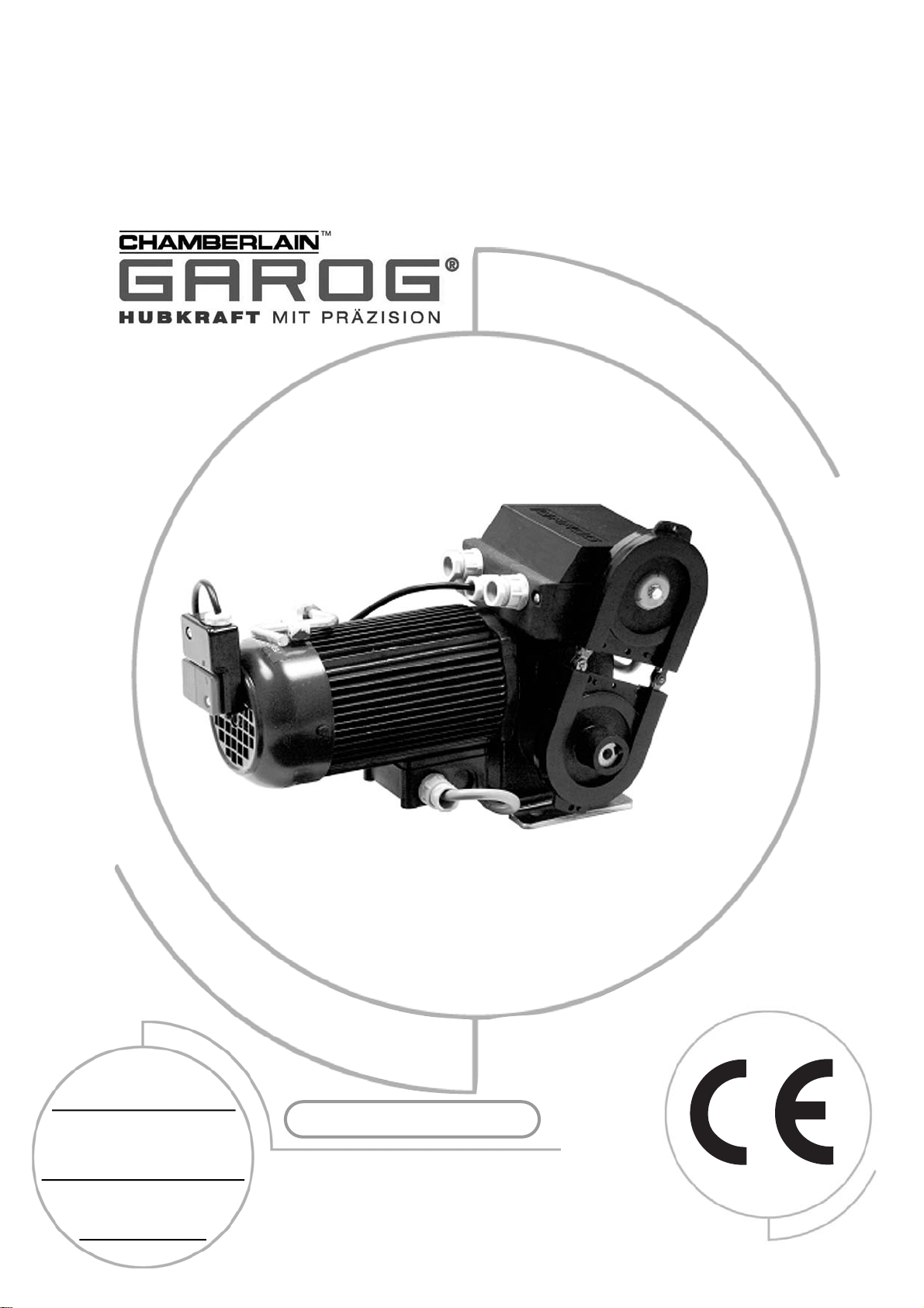
OPERATING MANUAL
INDUSTRIAL DOOR DRIVES
2 YEAR WARRANTY
Serial nummer:
(see motor gearbox)
Installed on:
Switchgear standart:
D-SERIES
Page 2

T ABLE OF CONTENTS P A GE 2
IMPORT ANT SAFETY AD VICE 3 - 4
GENERAL INFORMA TION 4
PREP ARATOR Y T ASKS 5
INST ALLATION ADVICE
MOUNTING ARRANGEMENT 6
INST ALLATION ADVICE
MOT OR CONNECTION 7
ELECTRICAL CONNECTIONS 8
CIRCUIT DIAGRAM KSAT 1/1S 9
GENERAL ADVICE
CONNECTION EXAMPLES 10 - 13
CIRCUIT DIAGRAM SEK P A GE 14
DIMENSIONAL DRA WING, DOOR DRIVE 15
DIMENSIONAL DRA WING
CHAIN WHEELS & DRIVE 16
LIFTING FORCE T ABLE 17
CALCULA TION OF
LIFTING SPEED 18
MAINTENANCE 19
MAINTENANCE PLAN
W ARRANTY 20
SP AREPARTS 21
NOTES 22 - 23
2
TABLE OF CONTENTS
Page 3
The door should be counterbalanced.
If this is not done then additional
measures must be taken, such as
unwinding protection, to guarantee
proper operation. Non-movable or
stuck doors must be repaired. Doors,
door springs, cables, pulleys,
retainers and rails are under extreme
tension in such situations and this
can lead to serious injuries.
Do not attempt to loosen, move or
realign the door yourself.
Contact your maintenance service.
Suitable protective clothing should be
worn during maintenance or installation
of the door opener. This includes safety
glasses, back supporting belt, and
protective gloves. When installing or
maintaining a door opener no jewellery,
watches or loose clothing may be worn.
When working from ladders or on
extended platforms the corresponding
safety procedures must be followed.
To avoid serious injuries resulting from
getting tangled or caught in the
mechanisms, all ropes and chains,
which are connected to the door,
must be removed before installing the
door opener.
During installation and connection of the
electrical supply the local building and
electrical regulations must be followed.
Power cables may only be connected to
a properly earthed network.
This system must not be installed in
damp or wet rooms.
Work on the door opener may only be carried
out by one (1) person working on his own.
When working on the door opener all
the local safety regulations must be
observed. Installation of this device
must be done according to EN12453.
The force on the closing door edge
must not exceed 150 N(15kg). If the
closing force is set to more than 150N
then the corresponding additional
safety accessories must be installed
(see "Installation of safety applications"). The force must never be
set to move a stuck door.
Too high a force leads to faults in the
proper operation of the reversing system
or to damage to the door.
To remind all operators of the safety
procedures the corresponding warning
sign should be attached beside the
operating control unit.
To avoid damage to the door all the
blocking devices should be deactivated.
If however the blocking devices must
remain in operation an unlatching switch
can be installed.
The three-switch block, main disconnecting switch and all other
control devices must be installed
within view of the door and out of
reach of children. Children should not
be allowed to operate switches or the
remote controller. Misuse of the door
opener can lead to serious injuries.
The door opener may only be
operated if the operator can see the
whole door area, if it is free from
obstacles and the door opener is
properly adjusted. No one may pass
through the door while it is moving
and children must not be allowed to
play in the vicinity of the door.
Before carrying out repairs or removing the covers on the door
opener, it is essential to ensure that
no one can inadvertently start the
drive by installing a lockout device or
disconnecting the cables.
This symbol means "Caution" and stands in front of safety advice intended to avoid
personal injury or material damage. Please read such advice carefully. The door drive is of
course designed and tested for safe operation. It is however only possible to guarantee this
if the following safety instructions are accurately followed during installation and operation.
This symbol is intended to advise that if the respective instruction is not followed serious
personal injury or material damage can occur.
IMPORTANT SAFETY INFORMATION
3
Before installation, operation or maintenance of this door drive,
this operating manual must be read through carefully
and all the safety advice must be followed.
Page 4
In doing so you should also follo w:
∙ The instructions in this manual
∙ All other project planning documents for the drive
∙ The start-up instructions and circuit diagrams
∙ The currently-valid national regulations (safety and accident prevention)
Guarantee, storage
It is essential to follow these instructions and advice since they are the basis for trouble-free operation as well as for any
guarantee claims. Check the delivery immediately after receipt for any transport damage. Report any damage immediately
to the transport company as well as to the supplier. If you do not install the geared motor straight away you should store it in
a dry, dust-free, low-vibration room at temperatures between 0 and +40°C.
Zustand bei Auslieferung
Delivered condition
Every geared motor is manufactured according to the valid technical documentation and subjected to a test run at
Chamberlain. We retain the right to make changes to technical data and design, which are in the interests of progress.
Dispatch takes place in the appropriate packaging.
4
WICHTIGE SICHERHEITSHINWEISE
Live and moving parts of electrical
machines can cause serious or fatal
injuries. The installation, connection
and starting up, as well as maintenance and repair work may only be
carried out by qualified specialist
personnel.
To avoid damage to the door or the
drive, all the locking devices must be
put out of operation. Set locking
device(s) to the "Open" position. If a
lock is to remain in operation an
unlatching switch must be installed.
Please find the technical data for the geared motor
from the type plate or from the attached documents.
We thank y ou for purchasing our pr oduct.
If you still have questions on the installation then please contact:
Chamberlain GmbH, Alfred-Nobel-Str. 4,
66793 Saarwellingen Germany
Tel: (0049)(0)6838-907222
Fax: (0049)(0)6838-907179
e-mail: info@garog-service.de
Internet: www.garog-service.de
GENERAL INFORMATION
Page 5

5
The drive may only be installed:
If the details on the rating plate on the drive correspond with the mains voltage.
If the drive is undamaged
If the ambient temperature is between 0 and 40°C
If the installation height is not more than 1000m above sea level
If the type of protection has been appropriately selected.
Output shafts and mounting surfaces are to be thoroughly cleaned to remove the corrosion protection agent (use standard
commercial solvent). To avoid material damage the solvent must not get onto the sealing edges of the rotary shaft seals.
Abrasive agents must not be used.
To avoid shaft breakages and hence serious or fatal injuries it is essential to note the following during mounting:
The precondition for suitable dimensioning of the shaft with respect to its fatigue strength is stress-free installation and an
immovable bearing device for the gearbox support as well as any additional or essential supporting bearings in each
direction as supplied by the user.
The machine frame and force introduction points are to be designed with respect to construction and strength according to
the bearing forces which arise. The gearbox housing with two bearings and all the other bearing points are located on a
common, stable framework on which the bearing surfaces have been machined in one operation. Thereby the installer
must ensure that any deformation of the frame under load will not have any negative influences on the shaft load. The
screws may only be fully tightened once the gearbox has been accurately aligned. Installation in damp rooms or in the open
air is only permitted following agreement with the manufacturer. If the drives are stored for a lengthy period of time it is also
necessary to discuss this with the manufacturer.
PREPARATORY MEASURES
Before starting the installation work make sure that all the
necessary safety measures have been implemented.
1. Installation
Place machine down on smooth mounting plate or aligned slide rails and tighten fixing
screws uniformly.
Make sure beforehand that:
The drive is not damaged or sticking
∙ The drive has been reprepared after a lengthy storage period
∙ The supply line is switched off and safeguarded against being switched on again
(VDE regs.) (VDE = German assoc. of electronic engineers)
∙ The connections have been made properly
∙ The turning direction of the geared motor is correct
∙ All motor protection devices are active
∙ No other danger sources exist
INSTALLATION ADVICE
Page 6
6
INSTALLATION ADVICE
Commissioning:
During commissioning check whether:
The drive does not get excessively hot
In the event of unusual running noises the drive must be stopped immediately and Customer Services should be
informed. If oil is lost Customer Services should be called, the oil level should be checked by means of the dipstick on the
vent screw and the drive must also be switched off if the level falls below the minimum filling quantity.
T o ensure efficient support in the event of a fault we require the following inf ormation:
The data from the type plate on your drive unit
∙ The type and extent of the fault
∙ When and under what accompanying conditions the fault occurred.
∙ Whether the drive was subject to speed variations or other distinctive happenings
Electrical connection
The connections according to the circuit diagram and the maintenance of the electrical drive may only be
carried out by electrical specialist personnel.
The corresponding accident prevention regulations must be followed.
For switching the motor and the brake connections, switching contacts of
utilization category AC-3 acc. to IEC 158 must be used.
∙ The types of line and their cross-sections must be selected according to the
relevant regulations. The nominal flows and the type of connection are given
on the motor type plate. The drive details must agree with the connected
values.
If operated with electronic control devices it is essential to take account of
the corresponding start-up instructions and circuit diagrams.
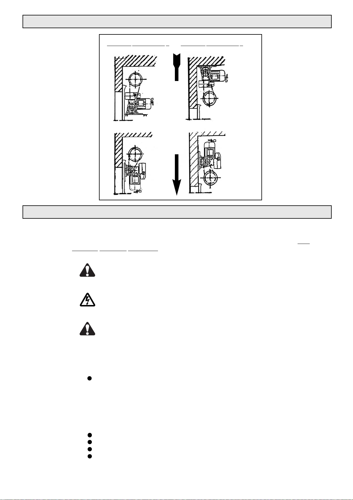
MOUNTING ARRANGEMENT
Closing direction
Mounting arrangement 1
Mounting arrangement 2
1a
2a
1b
2b
Page 7
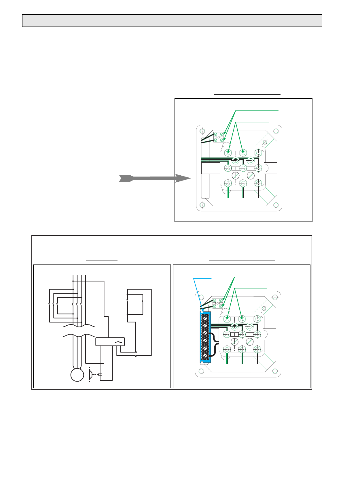
Connect motor:
1. According to circuit diagram; normally with star point in the case of delta/star connection of
asynchronous machines.
2. Check cross-section of wires
3. Firmly tighten connections and PE conductor
4. Check terminal boxes and tighten if necessary
Six-pin terminal boards are
normally used for three-phase motors
Display of a 9-pin terminal board
with star connection (400V):
Thermostatic switch opens at 130°C
Corresponding connecting option for brake
To avoid burning out of the motor winding it is obligatory!
A motor circuit-breaker or a protective system with built-in overcurrent relay is required if no PTC thermistor
or thermostats are provided.
Our guarantee for the winding lapses if the abovementioned motor protection is not provided.
Motor terminal board 2
Motor terminal board 1
Only for D4000 - D7000
DC Brake
7
Connecting example
For rectifier
ELECTRICAL CONNECTION
Temperature sensor
Terminal Board
N
L1 L2 L3
12345
K1 K2
12345
6
6
+
34
13 13
K1 K2
14 14
W2
U2
U1 V1 W1
L1 L2 L3
Rectifier
W2 U2
Temperature sensor
Terminal board
U1 V1 W1
V2
V2
M
3~
L1 L2 L3
Page 8
8
Before the installation of power cables and control devices it is essential to take note of all the
following specifications and warnings. If they are not heeded serious injuries or damage to the
drive can occur.
The control housing of the door drive may only be opened by trained"Chamberlain" specialist
personnel. If necessary please contact your local Chamberlain dealer.
Before electrical installation or the starting up of the drive please study the circuit diagram
carefully. The valid local regulations must be followed for all the electrical wiring work.
Before carrying out any maintenance work on the door drive it is first necessary to disconnect
the power supply / power transmission at the main switch.
After completion of the maintenance work the danger zone must be cleared and secured again
before restarting.
ELECTRICAL CONNECTION
If you require additional accessories or spare parts
please contact your local Chamberlain dealer.
CHAMBERLAIN - GmbH
Alfred-Nobel-Str. 4
66793 Saarwellingen
ORDERING FAX NO: (0049)(0)6838-907179
TECHNICAL HOTLINE: (0049)(0)6838-907222
l A: Pushbutton for control by holding down continuously
l B: Keyswitch, or suchlike for controlling by means of continuous actuation
l C: Limitation of driving force by force limiting (clutch) and protection devices
(safety edge padding).
l D: Device to detect people or obstacles which are on the ground on one side (inside) of the door
leaf (infrared light barrier)
l E: Device to detect people or obstacles which are on the ground on both sides
(inside and outside) of the door leaf (infrared light barrier).
ADVICE: For more detailed information see EN12453.
MATRIX FOR THE USE OF SAFETY EQUIPMENT
Control by continuous switch
operation
Pulse actuation within visual
range of door
Automatic control
Trained
people(inaccessible
to the public)
Group 1
A
C
C and D
(General public area)
Group 3
No info.
C and E
C and E
Public area
Group 2
B
C and D
C and E
TYPE OF CONTROL DOOR WILL BE USED BY
Page 9

GENERAL ADVICE
CIRCUIT DIAGRAM: KSAT
KSAT 1/1 S
9
M
3
PE
U1W1V1
N
L3L2L1 PE
14
13
13
14
K2
A1
A2
A2
K1
A1
K1
K2
AUF
ZU
T1
S1
S3
S2
S4
S5
2 4 6
1
3
5
2 4
6
1
3
5
K1
K2
X1
X2
WIRING
PE conductor GREEN-YELLOW 1,5
Main power circuit BLACK 1,5
Control circuit AC RED 0,75
Control circuit DC BLUE 0,75
2V
12
2
1
3
1
3
The corresponding connection options can be found in the following
figures A - G and the installation instructions in the appendix.
Note mounting arrangement of drive
For the 24V AC supply 2V and 1V are available at the terminals. The available power from the control
transformer is 6VA and is provided for the connection of a remote controller and a light barrier. Additional
consumers may only be connected if the overall power of 6 VA is not exceeded.
1. The terminal markings for the control stations, light barriers and remote controllers can vary
according to the manufacturer.
2. See the following pages with respect to the connection example F
In the event of a defective contact strip or coiled cable the system will automatically switch over to "dead
man operation". This type of circuit corresponds with EN 12354. It must be ensured by organizational means
that only authorized personnel can actuate the switch. It must be possible to view the full danger zone from
the control station.
K1 Contactor UP
K2 Contactor DOWN
T1 Control transformer 400/24V-18VA
F1 Control circuit fuse
(1,6 AT, 5x20mm
)
S1 Safety limit switch
S2 Safety limit switch, crank,
emergency chain, wire rope socket
S3 Temperature sensor - motor winding
S4
Limit switch UP
S5 Limit switch DOWN
X1 Terminal strip - supply cable
X2 Terminal strip - supply cable
Reversing contactor with mechanical latching
Type P [kW] I [A]
ABB-VB6 2,5 7,5
Tele-LC2K12 5,5 12
Page 10

CONNECTION EXAMPLES
10
23131X2
Schlüsselschalter
AUF
ZU
HALT
22
21 13
14
21
P
PE
Connection
e
xample B:
Connection
example A:
Self-latching in both directions. In the event of a defective contact strip or coiled cable the closing
movement can only be carried out from the keyswitch in the "dead man's circuit". This type of circuit
corresponds with EN 12354.
UP in self-latching, DOWN in dead man's circuit.
NO
UP/DOWN key
Single error protection devices are self-monitoring, i.e. they can detect an error within the circuit and in
the device connections. Such types of protection require the use of self-monitoring sensing devices.
UP
DOWN
STOP
Keyswitch
2V 2
12 3X2 3
STOP
KEY
STOP
3 keys
SI
Set-up
1
1
DOWN
U P DOWN
UP
Page 11

CONNECTION EXAMPLES
11
Connection example C:
UP in self-latching, DOWN in dead man's circuit.
NC
typ. Sicherheit
NC
Safety Typ
Slack rope
switch
Slack rope
switch
UP
Broken spring
protection system
Triple pushbutton
DOWN
STOP
Schlaffseilschalter
Schlaffseilschalter
X2
1
2331
HALT
Federbruch-
sicherung
AUF
21
22
21
22
21
13
14
13
14
13
ZU
22
Dreifachtaster
14
Page 12

CONNECTION EXAMPLES
12
Connection
example E:
Connection example D:
If the contact strip or light barrier is defective the door cannot be closed due to the missing circuit.
Connection of slack rope switches and safety switch for door with common cable to
door leaf.
1 or 2-channel remote controller, UP and DOWN by one command. If the top limit switch has not
been reached the door initially travels upwards if given a new command for safety reasons.
21
UP
22
21
STOP
22
21
DOWN
22
Triple pushbutton
31
3
2
121
2VX2
13
14
13
Slack rope
14
13
switch
Safety Device
Slack rope
14
switch
Door contact
2V 2
X2
12 3
1
PE
Safety device
UP
DOWN
STOP
21 13
22 14
21 13
22
14
UP
DOWN
STOP
2
P
21 13
22
1
123456 789101112
2
~
24V
Key2 Key1
14
2 - Channel remote controller
~
24V
Twin pushbutton
Keyswitch
Page 13

CONNECTION EXAMPLES
13
Connection example F:
Connection
example G:
If the contact strip or light barrier is defective the door cannot be closed due to the missing circuit.
UP and DOWN movements can be triggered with the pull switch. If the top limit switch has not been
reached the door initially travels upwards for safety reasons if given a new command.
Triple switch with integrated ON/OFF keyswitch to interrupt the control voltage.
X2
11 23121 312V
PE
2
1
OFF
ON
P
21
13
UP
22
14
Safety device
21
STOP
22
21
DOWN
22
13
14
13
14
Keyswitch ON/OFF
and triple pushbutton
UP
DOWN
STOP
Twin pushbutton
13
21
22
21 13
22
14
14
UP
DOWN
UP
DOWN
Pull switch
2V 1
X2
13
21
22
21 13
22
23
1
1
14
PE
2
1
2
13456
Safety device
~~
24V
Light barrier
14
Page 14

14
SEK 2/1 S
F1 Control circuit fuse 1,6 A (5x20)
S1 Safety limit switch
S2 Safety contact for emergency chain
or crank handle
S3 Temperature sensor in
motor winding
S4 Limit switch UP
S5 Limit switch DOWN
S6 Supplementary limit switch UP
S7 Supplementary limit switch DOWN
X1 Terminal strip - limit switch
X2 Terminal strip - suppl. limit switch
X3 Terminal strip - motor
CIRCUIT DIAGRAM: SEK
S1
F1
X1
J
S3
142 3 5678
S4
S4
S5
M
3
~
U1 V1 W1 PE
X3
S6 S7
X2 10911121314
Page 15

Fig. 2
= Feather key dimensions acc. to DIN 6885, T1 width x height in mm
Drive type: A1 A2 A3 A4 A5 A6 B1 B2 B3 B4 D1 D2 L1 L2 L3 L4 L5
D300 62 104 230 264 262 230 90 120 120 - 20 110 60 96 371 302 100
D500 69 118 260 295 266 235 105 135 218 121 25 138 80 105 322 297 100
D1000 62 120 266 304 261 245 105 136 240 156 30 138 110 155 395 100
D2500 88 167 325 303 287 125 168 300 35 176 145 209 505 100
D4000 105 208 358 365 340 140 174 330 45 194 200 262 627 200
D7000 140 282 448 443 420 150 200 330 50 218 270 348 677 200
Drive type: R1 R2 w x h
D300 75 69 6x6
D500 75 69 8x7
D1000 75 69 8x7
D2500 75 69 10x8
D4000 14x9
D7000 14x9
1)
1)
Fig. 1
See table below for Fig. 1 data
15
DIMENSIONAL DRAWING - DOOR DRIVE
Only for feather key
w x h DIN6885
Assembly dimensions with circuit breaker in normal position
Page 16

16
D
o
D
a
b
2
b
1
D
1
Drive- Hub wheel dim. Toothed- Outside- Pitch circle Inside Hub Toothed- Article-.
type In inches
(“)
ring rows diameter diameter diameter width ring width desciption-
Pitch x width Da mm D0 mm D
1 mm
b2mm b1mm
See table below for chain wheel sketch data
Sketch of chain wheel
Type: D300 D500 D1000 D2500 D4000 D7000
Motor power: P [kW] 0,22 0,37 0,74 1,85 3,00 5,20
Torque: M [Nm] 35 65 125 300 500 1100
Motor speed: n1 [min-1] 1370
Output speed: n2 [min-1] 32 32 32 32 28 26
Duty factor: Df S3=60%
Type of motor protect.: IP54
Operating voltage: U [V] 400V (380-415), 3ph, 50Hz
Nominal current (400V): Inom[A] 0,9 1,7 2,9 4,6 9 13
Output shaft: D [mm] 20 25 30 35 45 50
Weight: [kg] 10,8 16 21,5 35 61 98
Equipment
available for:
Emergency Emergency Quick-action Motor Built-in
crank handle manual chain clutch clutch clutch
A
A A A
A
A
B
B
B
B
B
SK
MS
EK
EK
EK
A
EK
SK
MS
MS
EK
A-1
DIMENSIONAL DRAWING - CHAIN WHEELS AND DRIVE
Fig. 3
Fig. 4
D300 1/2 x 1/16” 12 53 49 20 16 4,4 G-N2-12
D500 1/2 x 5/16” 12 53 49 25 16 7 G-5N-12
D1000 5/8 x 3/8” 12 66,5 61,5 30 25 8,7 G-N10-12
D2500 1” x 17mm 10 90 82 35 35 15 G-N25-12
D4000 1” x 17mm 10 90 82 45 35 15 G-N40-12
D7000 1 1/4 x 3/4 10 112 103 50 40 18 G-N50-10
Plan view of
LH drive
Plan view of
RH drive
Linksantrieb
Draufsicht
Rechtsantrieb
Draufsicht
Page 17

Lifting force in N with transmission ratio I = 1: 3
Drive torque Drum / Roller diameter in mm:
Type M [Nm] 100 160 190 220 250 270 300
D300 35 1.680 1.050 884 764 672 622 560
D500 66 3.168 1.980 1.667 1.440 1.267 1.173 1.056
D1000 125 6.000 3.750 3.158 2.727 2.400 2.222 2.000
D2500 300 14.400 9.000 7.579 6.545 5.760 5.333 4.800
D4000 500 24.000 15.000 12.632 10.909 9.600 8.889 8.000
D7000 1.100 52.800 33.000 27.789 24.000 21.120 19.556 17.600
Lifting force in N with transmission ratio I = 1: 4
Drive torque Drum / Roller diameter in mm:
Typ M [Nm] 100 160 190 220 250 270 300
D300 35 2.240 1.400 1.179 1.018 896 830 747
D500 66 4.224 2.640 2.223 1.920 1.690 1.564 1.408
D1000 125 8.000 5.000 4.211 3.636 3.200 2.963 2.667
D2500 300 19.200 12.000 10.105 8.727 7.680 7.111 6.400
D4000 500 32.000 20.000 16.842 14.545 12.800 11.852 10.667
D7000 1.100 70.400 44.000 37.053 32.000 28.160 26.074 23.467
17
A-2.1
A-2.2
A-2.3
= Measured at the rotor shaft at an assumed friction loss in the door system of 20%
"The thickness of the profile must be taken into account separately!"
1)
LIFTING FORCE TABLE
Lifting force in N with transmission ratio I = 1: 2,5
Drive torque Drum / Roller diameter in mm:
Type M [Nm] 100 160 190 220 250 270 300
D300 35 1.400 857 737 636 560 519 467
D500 66 2.640 1.650 1.389 1.200 1.056 978 880
D1000 125 5.000 3.125 2.632 2.273 2.000 1.852 1.667
D2500 300 12.000 7.500 6.316 5.455 4.800 4.444 4.000
D4000 500 20.000 12.500 10.526 9.091 8.000 7.407 6.667
D7000 1.100 44.000 27.500 23.158 20.000 17.600 16.296 14.667
1)
Lifting force in N with transmission ratio I = 1:1
Drive torque Drum / Roller diameter in mm:
Type M[Nm] 100 160 190 220 250 270 300
D300 35 560 350 295 255 224 207 187
D500 66 1.056 660 556 480 422 391 352
D1000 125 2.000 1.250 1.053 909 800 741 667
D2500 300 4.800 3.000 2.526 2.182 1.920 1.778 1.600
D4000 500 8.000 5.000 4.211 3.636 3.200 2.963 2.667
D7000 1.100 17.600 11.000 9.263 8.000 7.040 6.519 5.867
1)
1)
1)
A-2
Page 18

Table for determination of the lifting speed in cm/sec.:
Bale diameter- n2= 32 rpm
-1
n2= 28 rpm
-1
n2= 26 rpm
-1
[mm] 1:1 1:2 1:2,5 1:3 1:3,5 1:2 1:2,5 1:3 1:3,5 1:2 1:2,5 1:3 1:3,5
100 16,7 8,4 6,7 5,6 4,8 7,3 5,9 4,9 4,2 6,8 4,5 3,9 2,7
120 20,2 10,1 8,1 6,7 5,8 8,8 7,0 5,9 5,0 8,2 5,5 4,7 3,3
140 23,5 11,7 9,4 7,8 6,7 10,3 8,2 6,8 5,9 9,5 6,3 5,4 3,8
160 26,8 13,4 10,7 9,0 7,7 11,7 9,4 7,8 6,7 10,9 7,3 6,2 4,4
170 28,5 14,3 11,4 9,5 8,1 12,5 10,0 8,3 7,1 11,6 7,7 6,6 4,6
180 30,1 15,1 12,1 10,0 8,6 13,2 10,6 8,8 7,5 12,3 8,2 7,0 4,9
190 31,8 15,9 12,7 10,6 9,1 13,9 11,1 9,3 8,0 12,9 8,6 7,4 5,2
200 33,4 16,7 13,4 11,1 9,5 14,7 11,7 9,8 8,4 13,6 9,1 7,8 5,4
210 35,1 17,6 14,1 11,7 10,0 15,4 12,3 10,3 8,8 14,3 9,5 8,2 5,7
220 36,8 18,4 14,7 12,3 10,5 16,1 12,9 10,8 9,2 15,0 10,0 8,6 6,0
230 38,5 19,3 15,4 12,8 11,0 16,9 13,5 11,2 9,6 15,7 10,5 9,0 6,3
240 40,3 20,2 16,1 13,4 11,5 17,6 14,1 11,7 10,1 16,3 10,9 9,3 6,5
250 41,9 20,9 16,7 14,0 12,0 18,3 14,7 12,2 10,5 17,0 11,3 9,7 6,8
260 43,6 21,8 17,2 14,5 12,3 19,1 15,2 12,7 10,9 17,7 11,8 10,1 7,1
270 45,3 22,6 18,1 15,1 13,0 19,8 15,8 13,2 11,3 18,4 12,3 10,5 7,4
280 47,0 23,5 18,8 15,7 13,4 20,5 16,4 13,7 11,7 19,1 12,7 10,9 7,6
290 48,6 24,3 19,4 16,2 13,9 21,3 17,0 14,2 12,1 19,7 13,1 11,3 7,9
300 50,2 25,1 20,1 16,7 14,4 22,0 17,6 14,7 12,6 20,4 13,6 11,7 8,2
320 53,5 26,8 21,4 17,8 15,3 23,5 18,8 15,6 13,4 21,8 14,5 12,5 8,7
340 57,0 28,5 22,8 19,0 16,3 24,9 19,9 16,6 14,2 23,1 15,4 13,2 9,2
360 60,2 30,1 24,1 20,1 17,2 26,4 21,1 17,6 15,1 24,5 16,3 14,0 9,8
380 63,6 31,8 25,4 21,2 18,2 27,9 22,3 18,6 15,9 25,9 17,3 14,8 10,4
400 67,1 33,6 26,8 22,4 19,2 29,3 23,5 19,5 16,8 27,2 18,1 15,4 10,9
420 70,5 35,3 28,3 23,5 20,1 30,8 24,6 20,5 17,6 28,6 19,1 16,3 11,4
440 73,6 36,8 29,4 24,5 21,0 32,3 25,8 21,5 18,4 29,9 19,9 17,1 12,0
460 77,0 38,5 30,8 25,7 22,0 33,7 27,0 22,5 19,3 31,3 20,7 17,9 12,5
480 80,5 40,3 32,3 26,8 23,0 35,2 28,1 23,5 20,1 32,7 21,8 18,7 13,1
500 83,8 41,9 33,5 27,9 23,9 36,7 29,3 24,4 20,9 34,0 22,7 19,4 13,6
CALCULATION OF LIFTING SPEED
18
Vm (sm/sec)
Formula for roller door speed calculation:
Vm = Average lifting speed in cm/sec
D = Largest bale diameter in cm
d = Smallest bale diameter in cm
n = Nominal speed of drive in rpm
3,14 = Circle constant
π
Vm=
(D+d x 3,14 x n)
2 x 60
[cm/sec]
Page 19

MAINTENANCE
19
If for whatever reason your drive does not operate as desired or not as is described in the operating
manual, please first check whether you have read and correctly followed all the instructions. If faults are
still occurring please make contact with your local Chamberlain dealer who will be happy to support
you in rectifying the fault.
Before carrying out any maintenance work on the door drive it is first necessary to disconnect the
power supply / power transmission at the main/ emergency switch. All maintenance work may only be
carried out by trained "Chamberlain" specialist personnel. If necessary please contact your local
Chamberlain dealer.
MAINTENANCE PLAN
Maintenance
All gearboxes are filled with lubricant in the factory. This lubricant is suitable for at least 1000 operating
hours. After this time or at the very latest every 6 years it is advisable to renew the special oil. For this
purpose only SHELL OMALA 460 should be used in the following filling quantities. The oil quantities for
the different types of drive are as follows:
In the case of low running times and favourable temperature conditions the lubricant may still be fit for use even
after 6 years. In this case however we still recommend that about 1/3 of the given amount of lubricant is added.
If losses of lubricant take place it is necessary to top up with the special oil given above at the correct
time.
Before starting up, a check should be made on whether all the internal and external conditions have been met so
as to ensure perfect functioning.
Drive Filling quantity
D300 60 cm
D500 100 cm
D1000 130 cm
Drive Filling quantity
D2500 260 cm
D4000 500 cm
D7000 1350 cm
3
3
3
3
3
3
Page 20

GUARANTEE AND STORAGE
Definition of qualified personnel
Within the meaning of the operating manual and the warning information concerning the product itself, these are people
who are familiar with the setting out, installation, commissioning and operation of the product and have suitable
qualifications for their work, such as:
a. Training or instruction in, and authorization to connect up, switch on and off, earth and mark power circuits and
devices according to the engineering safety standards.
b. Training or instruction according to engineering safety standards in the care and use of the appropriate safety
equipment.
c. Training in first aid.
The fitting of drive elements
The fitting of drive elements such as rope pulleys, wheels etc is best done after previous warming of the respective part.
The preheating temperature should be 100°C.
A precoating of a copper paste eases mounting and provides long-term protection from frictional corrosion.
To avoid damage to bearings, housings and shafts the drive elements must never be mounted on the end of the
shaft by hammer blows.
The fitting of drive elements by means of pressure requires a force introduction surface (seating on output shaft).
Fitted transmission elements must be counterbalanced and must not cause any non-permitted radial or axial forces.
The corresponding tolerances must be observed during the fitting work (see dimension drawing).
20
Page 21

D300/32
D500/32
D1000/32
D2500/32
D4000/28
D7000/26
041G - KS KS Crank drive safety switch
21
The spare parts kits obtainable for your drive are given in the following parts lists. If your drive
already has optional modifications and/or accessories, certain parts can be added or removed from
the list. Possibly individual parts of a kit are not obtainable - please contact a member of staff
responsible for spare parts and maintenance. He will be happy to inform you about the availability of
individual parts in the kits listed below.
You will find general information on ordering on page 24.
LIMIT SWITCHES /CIRCUIT BREAKERS
041G -SEK2/1SL SEK2/1L - LH travelling nut limit switch
041G -SEK2/1SR SEK2/1R - RH travelling nut limit switch
041G -KSAT1/1S KSAT Circuit breaker
LIMIT SWITCHES /CIRCUIT BREAKERS
041G-NHK-D300 Emergency manual crank handle D300
041G-NHK-D500 Emergency manual crank handle D500-1000
041G-NHK-D1500 Emergency manual crank handle D1500-2500
041G-NHKD3/6000 Emergency manual crank handle D3000-7000
MECHANICAL SPARE PARTS
MOTOR / GEARBOX
SPARE PARTS
Page 22

NOTES
22
Page 23

NOTES
23
Page 24

01-16167-D
This is how to order:
When ordering spare parts or accessories we need
the following information from you:
Part number, description, model number
IN EUROPE
ADDRESS FOR ORDERS:
Chamberlain
-GmbH
Alfred-Nobel-Str. 4
66793 Saarwellingen
TEL. NO. FOR ORDERS:
+(49) 6838-907222
FAX NO. FOR ORDERS:
+(49) 6838-907179
TECHNICAL HOTLINE:
+(49) 6838-907222
ONLINE-SERVICE:
www.garog-service.de
IN NORTH AMERICA
ADDRESS FOR ORDERS:
The Chamberlain Group Inc.
Electronic Parts and Service Department
2301 N. Forbes Blvd., Suite 104
Tucson, Arizona 85745 USA
TEL. NO. FOR ORDERS:
1-520-792-0511
FAX NO. FOR ORDERS:
1-520-884-0966
TECHNICAL HOTLINE:
1-800-528-2806
Declaration of Conformity
The industrial door drive . . . . . . . . . . . . . . . . . . . . . . . . . . . . . . . . . . . . . . . . .
corresponds to the applicable sections and standards . . . . . . . . . . . . .
in accordance with the regulations and amendments
of EU Guidelines……………………………………………………………73/23EEC & 89/336/EEC
Manufacturer's Declaration
Provided that the industrial door drive, Series D type is installed and maintained in accordance with all the
manufacturer's instructions in conjunction with an industrial door, which is also installed and maintained in accordance
with all the manufacturer's instructions, it meets the regulations of EU Guideline 89/239/EEC in its amended form.
Chamberlain-GmbH
66793 Saarwellingen
August 2004
 Loading...