

Page 1

Keypad Programming Manual For
EL Models
Telephone Entry/Access Control System
Models EL25 and EL2000SS
LiftMaster
300 Windsor Drive
Oak Brook, IL 60523
LiftMaster.com
For how-to videos, visit the
LiftMaster Training Academy at
LiftMastertraining.com
Page 2

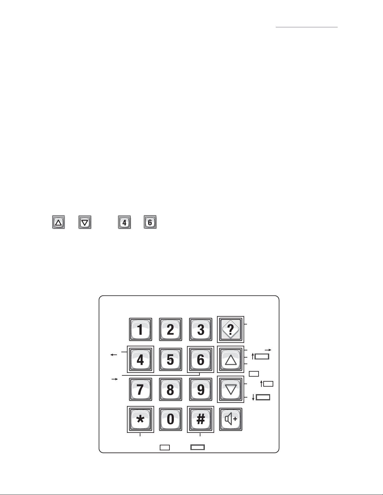
KEYPAD PROGRAMMING GUIDE
1. CCTV Camera: Optional
2. Call Button: Press to call a resident inside the complex, or office.
3. Status LED: Solid Red (EL25 idle power, doors are locked); Blinking Red
(Strikes and Out for a door); Solid Green (Granted access for a
door); Blinking Green (Latch for a door is unlocked). NOTE: All
references are for door 1.
4. Microphone
5. Asterisk Key: "Start Programming Mode" or a Cancel Key.
6. Pound Key: Data field separator, optional skip step or enter key.
Call a resident using the directory codes.
7. Visitor Volume Key: Visitors can physically adjust the speaker
volume of the unit. Unit will return to programmed volume setting
when transaction complete.
8. Up/Down Key: Serves no function on this unit.
9. Help Key: Receive a quick audio description of a keypad button by
pressing the Help key followed by the key to be described.
10. Lights: Top and Bottom of Keypad.
11. Speaker: Allows resident and visitors to communicate; plays responses to
communicate programming or function commands.
1. CCTV Camera: Optional
2. Call Button: Press to call a resident
inside the complex, or office. Also
when calling someone using the
directory code listing.
3. Microphone
4. Asterisk Key: "Start Programming
Mode" or a Cancel Key.
5. Pound Key: Data field separator,
optional skip step or enter key. Call a
resident using the directory codes.
6. Visitor Volume Key: Visitors can
physically adjust the speaker volume of
the unit. Unit will return to
programmed volume setting when
transaction complete.
7. Up/Down Key: For scrolling through
tenant listing.
8. Help Key: Receive a quick audio
description of a keypad button by
pressing the Help key followed by the
key to be described.
9. Speaker: Allows resident and visitors
to communicate; plays responses to
communicate programming or function
commands.
10. LCD Display (optional)
11. Postal Plug
3
11
9
EL25
1
2
3
4
1
10
4
2
10
5 7
6
EL2000SS
8
7
6
5
11
11
11
9
8
1
Page 3

TABLE OF CONTENTS
Programming Numbers Page
Quick Reference Guide (Default Factory Settings) “ALL” 4-8
Introduction
Single Family Residence (NPB)
Multi-Resident Complex (Dial-Out or Manager Sharing)
Sample Layouts and Your System Layout
Programming Single Unit Overview
Programming Basics
Enter Programming Mode
Exit Programming Mode
System Feedback / Responses (Beeps)
Sending Direct Commands from Resident’s Phone
Programming Multiple Units Overview 2 111 20
Setup “Your Settings”
Getting Started
Setup External Access Control Devices
Your Door Settings with Examples
Example Setups
Directory Codes
About Directory Codes
Set a Directory Code Length
Add, Edit, or Delete Directory Codes
Delete ALL Directory Codes
Enable or Disable Do Not Disturb Schedule
Enable or Disable Call Forwarding (Directory Calls)
Add/Modify Resident DnD and/or Call Forwarding
Activate or Deactivate a Directory Code
Directory Code Display Option/Resident Display Option
Verify a Directory Code
Entry Codes
About Entry Codes
Set an Entry Code Length
Add, Edit, or Delete Entry Codes
Activate or Deactivate an Entry Code
Verify an Entry Code
Access Cards
About Cards
Add, Edit, or Delete Cards
Activate or Deactivate a Card
Verify a Card
Facility Codes
Card Types
+ 6-Digit Password 16
***
016
1 3 21
60 61 65 66 22-24
629
40 41 44 48 29-30
201 31
10 31
46 31
49 32
45 32
141 33
47 33
735
50 51 54 57 75 58 59 202 35-38
56 38
55 38
78 80 81 82 88 203 40-42
87 42
86 43
74 73 43
71 43
11-13
14-15
17-18
26-27
9
9-10
19
25
28
34
39
2
Page 4

TABLE OF CONTENTS
Programming Numbers Page
Remote Controls 44
Time Zones, Holidays and Clock
About Time Zones
Creating Time Zones
Setting Holidays
Assigning Door Use and Unlock Time Zones
Deleting ALL Time Zones
Setting the Clock
Features
Setting Anti-Passback
Configuring the Alarm Features
Changing or Verifying the Unit Password
Communications to and from Unit
Telephone-Unit Settings
Call Quality Settings
Enable or Disable Call Waiting
Maximum Modem Speed
Visitor Communication Settings
LCD Visitor Messages
Postal Lock/Autocall/Exit/Door Sensor Devices
Postal Lock Switch
Autocall Device
Request to Exit Device (REX)
Door Sensing Devices
Direct Commands from the Phone 21 120 121 122 123 124 125
Real-Time Monitoring
Reset/Restore the Unit and Database 28 29 206 66
Warranty 67
Glossary 68-69
Appendix 70-71
30
32 45
63 11 31 46
205 47
3 4 47
12 64 13 105 58 48-49
102 103 17 104 49-50
151
115 16 109 113 20 110 52-54
18 19 106 54
955
118 55
23 22 116 5 26 160 25 56-57
69 60
70 60
67 61
68 62
126
24 66
44
45
58-59
63-65
3
Page 5
QUICK REFERENCE GUIDE
GUIDE FOR KEYPAD PROGRAMMING THE UNITS
Optional Steps Indicated in BOLD type, all other steps are Required.
Programming
Number
***
016
151
220
347
447
557
629
735
955
10 31
11 46
12 48
13 48
14
15
16 53
17 50
18 54
19 54
20 53
21 63
22 56
23 56
24 66
25 57
Page Description of Task
16
Entering Programming Mode
Exiting Programming Mode 0 #
Change or Verify the Unit’s
Password
Set Unit ID Number and No. in Chain Unit ID 1,
Set the Clock 3 # yymmdd # (day of the week) # hhmm #
Enable/Disable Daylight Savings
Time
Set Visitor Talk Time 60 Seconds 5 # (15-250 seconds) #
Set Directory Code Length 3 Digits 6 # (1-4 ) #
Set Entry Code Length 4 Digits 7 # (3-9) #
Enable/Disable Call Waiting Enabled 9 # (0=disable; 1=enable) #
Enable/Disable Do Not Disturb
Schedule
Enable/Disable Unlock Schedule Enabled 11 # (0=disable; 1=enable) #
Enable/Disable Anti-Passback Disabled 12 # Enable/Disable True Anti-Passback
Set Anti-Passback Time 3 Minutes 13 # (1-60 minutes) #
Set Maximum Number of Rings
Allowed Before Aborting Attempt
Set Standard Single Ring or Double
Ring Response
Number of Rings Before Unit
Answers
Set “Strikes and Out” 3 Errors 17 # (max errors, 0-5) #
Set Speaker
Set Voice Response Volume
Set Beep Response Volume
Set Microphone Volume 5 19 # (0=mute, 1-10, 1 is low and 10 is
Enable/Disable the Telco Mode Enabled 20 # (0=disable; 1=enable) #
Enable/Disable Direct Commands Enabled 21 # (0=disable, 1=enable) #
Enable/Disable Voice Mail Disabled 22 # (0=disable, 1=enable) #
Enable/Disable Access Granted
Beeps
Enable/Disable Real-Time Monitoring Disabled 24 # (0=disable, 1=enable) #
Return to Menu Programming 25 #
Factory
Setting
(6 Digit Password)
***
000000
Chain No. 1
Enabled 4 # (0=disable; 1=enable) #
Disabled 10 # (directory code) # (0=disable;
5 Rings 14 # (1-9) #
1=Double
Ring
5 Rings 16 # (0-15) # Each unit in chain must have
5, 2, 2 18 # (0=mute; 1-10, 1 is low and
Enabled 23 # (0=disable, 1=enable) #
1 # (1 to change; 2 to verify) # (six-digit
coded) #
2 # (unit ID number, 1-7) #
(Number of Units in Chain, 1-7) #
1=enable) #
(0=disable; 1=enable) # Enable/Disable
Timed Anti-Passback (0=disable; 1=enable) #
15 # (0-1; 0=one long ring, 1=double ring)
#
same setting
10 is high) # (0=mute; 1=low;
2=medium; 3=high) # (0-3) #
high) #
Programming
Procedure
26 57
Enable/Disable “Announce All Doors/
Access Granted”
Disabled 26 # (0=disable, 1=enable) #
IMPORTANT: The Pound Key (#) must be used as Data Field Separator and to Save Data at the end of the sequence.
Time must be entered using a 24-hour format (8am=0800, 3pm=1500 etc.). If you make an error during an entry,
press the asterisk key (*) to begin again.
4
Page 6

QUICK REFERENCE GUIDE
Programming
Number
28
29 66
30 45
31 46
32 45
40 29
41 30
44 30
45 32
46 31
47 33
48 30
49 32
50 35
51 36
54 36
55 38
56 38
Page Description of Task
66
Restore Factory Settings 28 # 101010 #
Reset the Unit 29 # 101010 #
Create a Time Zone 30 # (time zone number, 2-63) # (segment
Assign Door Auto Lock/Unlock
Schedule
Setting Holidays 32 # (1=add, 2=verify, 0=delete) # (yymmdd;
Add a Basic Directory Code Enabled 40 # (directory code) # (phone number) # (phone
Add or Edit a Full Function
Directory Code
Change a Directory Code
ONLY
Activate/Deactivate a Directory
Code
Enable/Disable Call Forwarding
(Directory Calls)
Verify a Directory Code 47 # (directory code) #
Delete a Directory Code 48 # (directory code) #
Enable/Disable Call Forwarding
and Do Not Disturb Schedule
with Residence “Call Button”
Only
Add a Basic Entry Code 50 # (entry code) #
Add/Edit a Full Function Entry
Code
Change Entry Code ONLY 54 # (entry code to change) # (new entry code) #
Verify an Entry Code 55 # (entry code) #
Activate/Deactivate an Entry
Code
Factory
Setting
number; 99) # (starting time=hhmm; 99) #
(ending time=hhmm) # (day of week, 1-8;
1=Sunday; 7=Saturday; 8=holiday) #
Disabled 31 # (door 1-4) # (time zone, 2-63; 99) #
yy=year, mm=month, dd=day of the month) #
extension) #
41 # (directory code) # (phone number) # (phone
ext) # (DnD schedule number, 0-63) # (enable/
disable call fwd) # (call fwd schedule number,
0-63) # (new call fwd phone number) # (call
fwd phone ext) #
44 # (new directory code) # (directory code to
change) #
45 # (directory code) # (0=deactivate; 1=activate)
# (0=don’t use start; 1=use start) # (Start
Date=yymmdd) # (Start Time=hhmm) # (0=don’t
use end; 1=use end) # (End Date=yymmdd) #
(End Time=hhmm) #
Disabled 46 # (directory code) # (0=disable; 1=enable) #
(schedule number, 0-63) # (new call forward
phone number) # (call forward phone
extension) #
Disabled 49 # DnD Enable (1)/Disable (0) # DnD Schedule
(0-63) # Call Forward Enable/Disable
(0=disable; 1=enable) # Call Forward Schedule
(schedule number, 0-63 # (new call forward
phone number) # (call forward phone
extension) # (call forward extension delay, 0 to
30 sec.) #
51 # (entry code) # (schedule for door 1, 0-63)
# (schedule for door 2, 0-63) # (schedule for
door 3, 0-63) # (schedule for door 4, 0-63) #
56 # (entry code) # (0=deactivate; 1=activate) #
(0=don’t use start; 1=use start) # (Start
Date=yymmdd) # (Start Time=hhmm) # (0=don’t
use end; 1=use end) # (End Date=yymmdd) #
(End Time=hhmm) #
Programming
Procedure
5
Page 7

QUICK REFERENCE GUIDE
Programming
Number
57
58 37
59 37
60 24
61 24
63 46
64 48
65 23
66 23
67 61
68 62
69 60
70 60
71 43
73 43
74 43
75 36
78 40
80 40
Page Description of Task
36
Delete an Entry Code 57 # (entry code) #
Assign Utility Option Off 58 # (entry code) # (Option; 0=Off,
Assign Special Use Entry Code 59 # (entry code) # enable/disable #
Assign Each External Access
Control Device a “Door Number”
Assign “Each” Door Number to
One or More Relays
Assign Door Use Time Zone Enabled 63 # (door 1-4) # (time zone, 0-63) #
Set Anti-Passback Entry/Exit for
Specific Devices
Set Each “Relay Mode” to get
the Appropriate Response
Set Each Relay’s “Activation
Time”
Request to Exit Device (REX) R1=Door 1
Door Sensing Devices DS1=Door 1
Postal Lock Switch Door 1 69 # (door 0-4; 0=no postal lock) #
Autocall Device 0000 70 # (relays to activate 0000-1111) #
Set the Default Card Type 30-bit 71 # (26 or 30) # (Factory Default: 30)
Set the Default Facility Code 0 73 # (0-255) #
Enable or Disable Ignore Facility
Code when a Card is Used
Change Entry Code Door Access All Doors 75 # (entry code) # (door 0=any door,
Change Card Code Door Access All Doors 78 # (card code) # (facility code) #
Add a Basic Card 80 (card PIN code) # (facility code) #
Factory
Setting
1=Daily, 2=Weekly, 3=Never) # (number
of uses 1-15)
Main keypad
assigned door1
Device 1=door 1
Device 2=door 2
Device 3=door 3
Device 4=door 4
D1=Relay 1
D2=Relay 2
D3=Relay 3
D4=Relay 4
Disabled 64 # (device 0-4) # (0-3; 0=disable, 1=set
All Relays =
“1-Strike”
All Relays =
10 seconds
R2=Door 2
R3=Door 3
R4=Door 4
DS2=Door 2
DS3=Door 3
DS4=Door 4
Enabled 74 # (0=disable; 1=ignore) #
60 # (device 1-4) # (door 1-4) #
61 # (door 1-4) # (relays to activate
0000-1111) # Order of relay is: relay
4-relay -3 -relay 2-relay 1 for an example
if you want relay 4 active you would enter
1000, if you want relay 1 active you
would enter 0001
device to timed anti-passback, 2=set
device to true anti-passback-entrance,
3=set device for true anti-passback-exit)
#
65 # (relay 1-4) # (1=strike, 2=shunt,
4=alarm, 5=control) #
66 # (relay 1-4) # time (1-300 seconds)
67 # (REX number 1-4) # (select REX
option: 0=disabled, 1=use your door
settings or 2=use specific relay(s)
0000-1111) # Order of Relays are 4321
68 # (sensor number 1-4) # (select
sensor option: 0=disabled, 1=use your
door settings or 2=use specific relay(s)
0000-1111) # Order of Relays are 4321
Order of Relays are 4321 (Factory
Default: 0000)
1=door 1, 2=door 2, 3=door 3, 4=door 4)
#
(card type, 26 or 30) # (door 0=any door,
1=door 1, 2=door 2, 3=door 3, 4=door 4)
#
(card type, 26 or 30) #
Programming
Procedure
6
Page 8
QUICK REFERENCE GUIDE
Programming
Number
81
82 41
87 42
88 42
102 49
103 50
104 50
105
106 54
109 53
110 54
111 20
113 53
115 52
116 56
118 55
120 63
121 64
Page Description of Task
41
Add or Edit a Full
Function Card
Add a Group of Cards
at Once
Activate or Deactivate
a Card
Delete a Card 88 # (card PIN code) # (facility code) # (card type, 26 or
Configure “Door Held
Open” Alarm Feature
Configure “Door
Forced Open” Alarm
Feature
Configure “Strikes and
Out” Alarm Feature
49
Enable or Disable AntiPassback Forgiveness
at Midnight
Enable or Disable Echo
Cancellation by
Channel
Override Telephone
Company Answering
Service
Set a Phone Number’s
Extension Delay Time
Verify Unit Number 111 #
Dial “0-9” First to Get
an Outside Line Using
a Automated Phone
System
Set Alternative Prefixes Normal 115 # (normal-00, mixed-01, asterisk-02, pound-03,
Change the Visitor Call
Response Keys
Configure Maximum
Modem Speed
Talk through the Unit
Speaker
Cycle Door 121 # (door 1-4) #
Factory
Setting
81 # (card PIN code) # (facility code) (card type, 26 or
30) # (schedule for door 1, 0-63) # (schedule for door 2,
0-63) # (schedule for door 3, 0-63) # (schedule for door
4, 0-63) #
82 # (card PIN code start range) # (card PIN code end
range) # (facility code) # (card type, 26 or 30) #
(0=deactivate, 1=activate) # (schedule for door 1, 0-63)
# (schedule for door 2, 0-63) # (schedule for door 3,
0-63) # (schedule for door 4, 0-63) # name (0-20
characters) #
87 # (card PIN code) # (facility code) # (card type, 6 or
30) # (0=deactivate; 1=activate) # (0=don’t use start;
1=use start) # (Start Date=yymmdd) # (Start Time=hhmm)
# (0=don’t use end; 1=use end) # (End Date=yymmdd) #
(End Time=hhmm) #
30) #
Disabled 102 # (alarm option; 0=disable, 1=enable until relay time
expires, 2=enable until alarm clears) # (relay group, 0000-
1111) # Order of relays is 4321
Disabled 103 # (alarm option; 0=disable, 1=enable until relay time
expires, 2=enable until alarm clears) # (relay group, 0000-
1111) # Order of relays is 4321
Disabled 104 # (alarm option; 0=disable, 1=enable until relay time
expires, 2=enable until alarm clears) # (relay group, 0000-
1111) # Order of relays is 4321
Enabled 105 # (0=disable; 1=enable) #
Enabled 106 # (1=Mic/Spkr; 2=Resident; 3=Telco #; 0=disable;
1=enable)
Disabled 109 # (0=no; 1=yes) # Default is “No”
No Delays 110 # (directory code) # (phone extension delay) # (call
forward extension delay) #
Disabled 113 # (0=disable; 1=enable) # (0-9, when enabled) #
number-1n) # each unit in chain must have same setting
9, 5, 3, 7,
2, 1,*
14400 118 # Speed (14400, 9600, 2400, 1200) #
116 # (activate door 1) # (activate door 2) # (activate
door 3) # (activate door 4) # (call wait toggle) # (extend
talk time) # (hang up and deny access) #
120 #
Programming
Procedure
7
Page 9

QUICK REFERENCE GUIDE
Programming
Number
122 64
123 65
124 65
125 65
126 65
141 33
201 31
202 38
203 42
205 47
206 66
Page Description of Task
Toggle Door Open/Close Until 122 # (door 1-4) # (end time=hhmm) #
Get Door Status 123 # (door 1-4) #
Release Door 124 # (door 1-4) #
Enable/Disable Call Forwarding For
Residence
Enable/Disable Do Not Disturb For
Residence
Directory Code Display Option/
Resident Display Option
Delete ALL Directory Codes 201 # 101010#
Delete ALL Entry Codes 202 # 101010#
Delete ALL Cards 203 # 101010#
Delete ALL Time Zones 205 # 101010#
Delete ALL Access
Codes from Database
Factory
Setting
125 # (0=disable; 1=enable) #
126 # (0=disable; 1=enable) #
0, 1, 2 or 3141 # (directory code) # (hidden attribute
option) # (hidden option; 0=show name and
code, 1=name only, 2=code only, 3=hide) #
206 # 101010#
Programming
Procedure
To enter programming mode from the keypad Press *** and the 6-Digit Password (audio feedback will be heard)
Exiting programming mode allows changes to take effect
IMPORTANT:
• The Pound Key (#) must be used as Data Field Separator and to Save Date at the end of the sequence.
• Time must be entered using a 24-hour format (8am=0800; 3pm=1500 etc.).
• Audio Feedback: Programming input is valid. Audio Feedback: Input is not valid.
• If you make an error during an entry, press the asterisk key (*) to begin again.
8
Page 10

INTRODUCTION
The sample installations on the next few pages will help familiarize you with the features of your unit. You MUST
know how your system is laid out to program it with this manual. If you have questions about your configuration,
please contact your installing dealer for more information.
SINGLE FAMILY RESIDENCE (NPB)
This type of installation utilizes the "No Phone Bill" (NPB) feature. When a visitor contacts the resident at the unit, it
does not dial a separate number to reach you in your residence. The unit essentially functions as an intercom with
your residence phone. Therefore, the NPB does not require the use of directory codes, since the unit will only need to
ring a single telephone line to the house. When a visitor arrives, they will simply press the unit’s "Call" button to
contact the resident.
Telco Phone Line
AUG 10, 2005
WELCOME
Bypass
Board
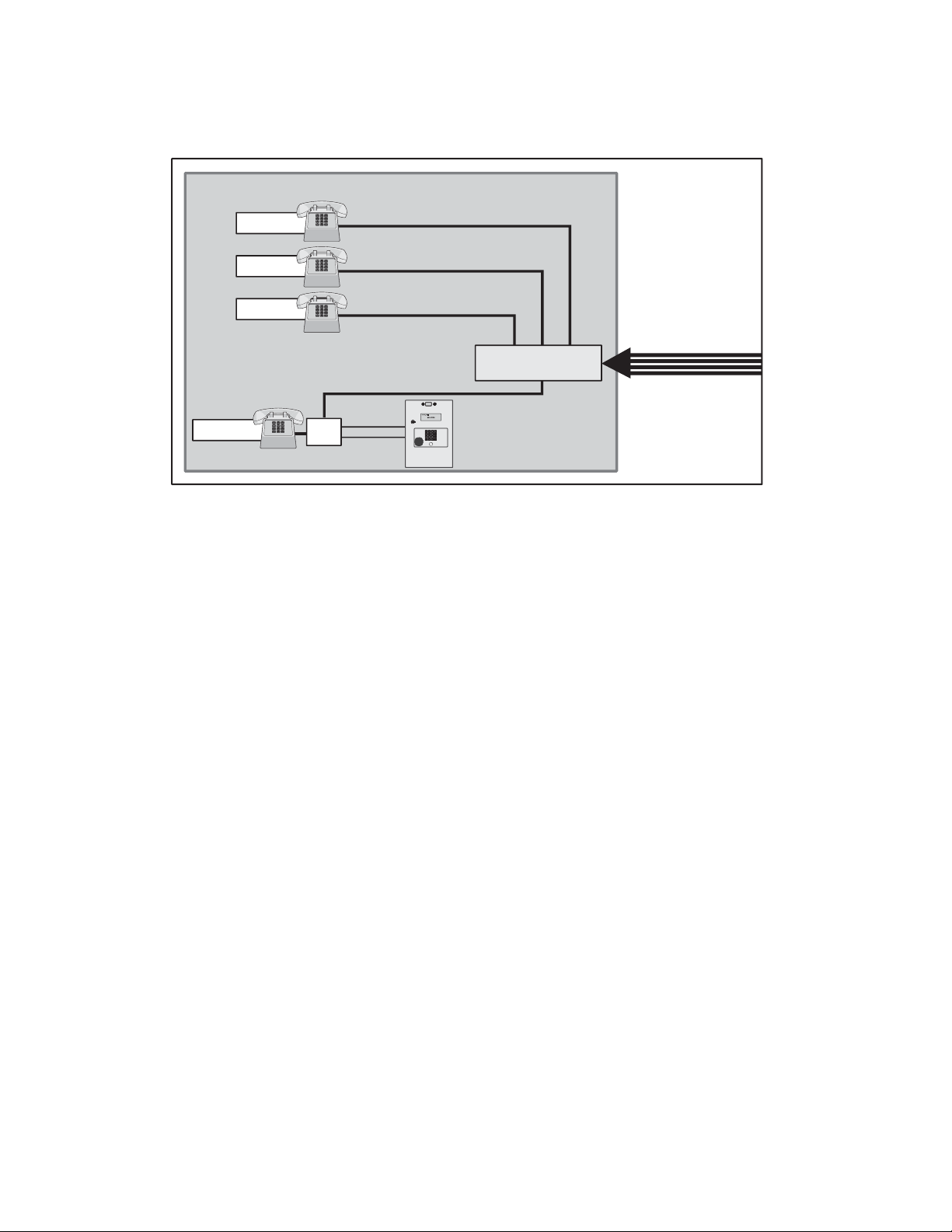
MULTI-RESIDENT COMPLEX (DIAL-OUT)
This installation utilizes the dial-out feature. Each resident has a separate phone number. The unit dials the resident’s
numbers using preprogrammed Directory Codes. Because the unit dials a separate phone number to contact the
resident, the "Call Waiting" and "Direct Command" features will not work. The unit must be remotely programmed.
Building/Complex
Resident
Resident
Resident
Manager
separate phone number
separate phone number
separate phone number
separate phone number
Telco Phone Lines
Phone Junction Box
separate phone number
9
Page 11
MULTI-RESIDENT COMPLEX (MANAGER SHARING)
With this type of installation, the manager has the same features as the single family residence (page 9). The unit can
be programmed remotely or locally. Visitors can call the manager directly using "Call" button or contact residents
using preprogrammed Directory Codes.
Building/Complex
separate phone number
separate phone number
separate phone number
Telco Phone Lines
Phone Junction Box
Manager
Resident
Resident
Resident
Bypass
Board
NPB MULTI-RESIDENT COMPLEX
Modes of Access
Visitors or residents of a building or complex controlled by a unit can gain access using one of the following
methods:
Resident Phone (Directory Codes): A visitor may dial a resident’s directory code from the unit to contact him/her.
The resident can then decide to grant or deny the visitor access to the building or complex.
Keypad (Entry Codes): A resident may enter a valid entry code on the unit’s keypad or an optional external
Wiegand-compatible keypad to enter the building or complex.
Optional Card Readers (Cards): A resident may present a valid card to an optional Wiegand-compatible card
reader to enter the building or complex. Card readers are typically located near an entry/exit area
(e.g., door or gate).
Optional Radio Frequency Receivers (Remote Controls): A resident may choose to use an optional Passport
remote control or other optional Wiegand-compatible receiver to enter the building or complex. For example, these
may be used to open a vehicular gate.
10
Page 12
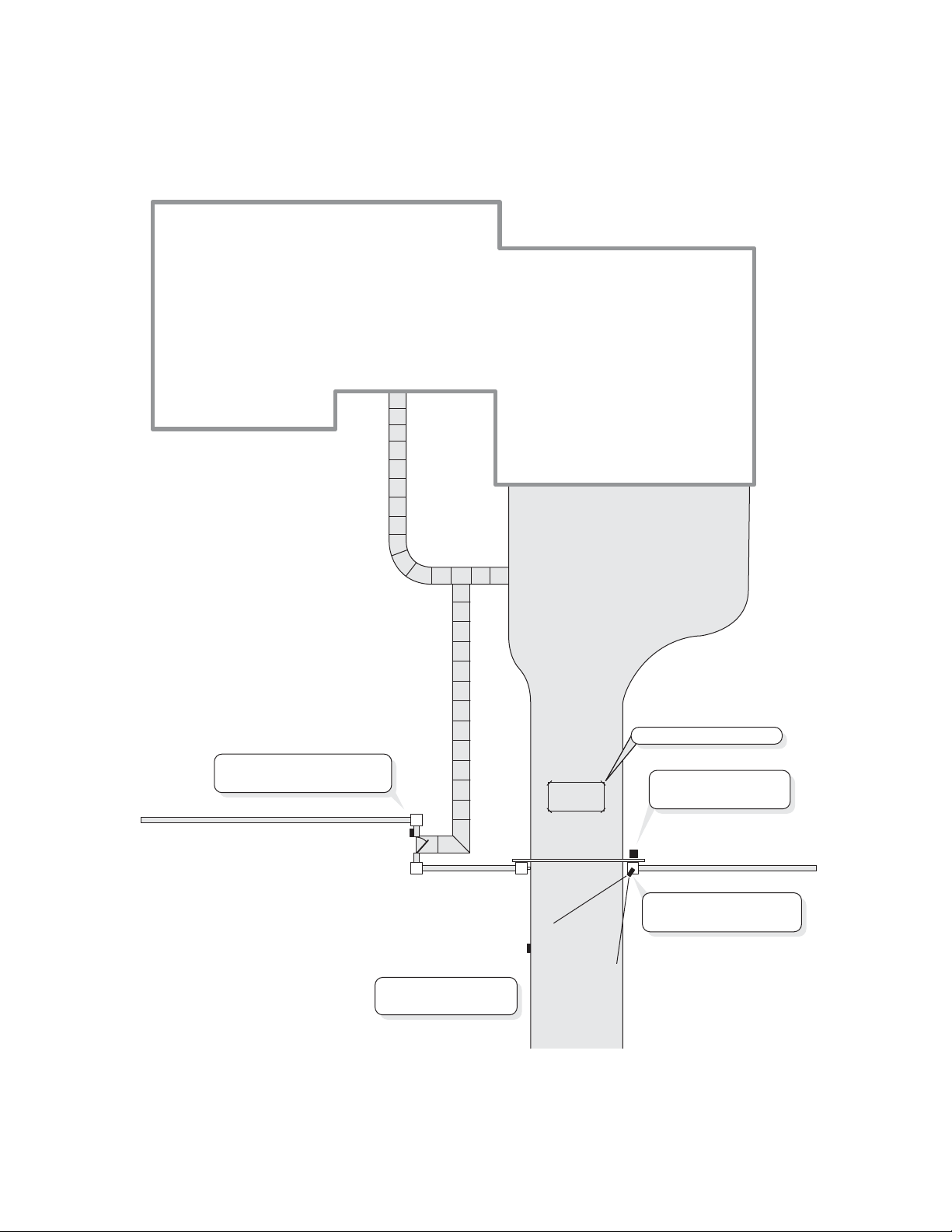
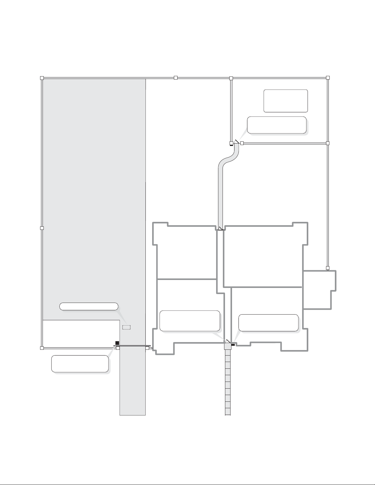
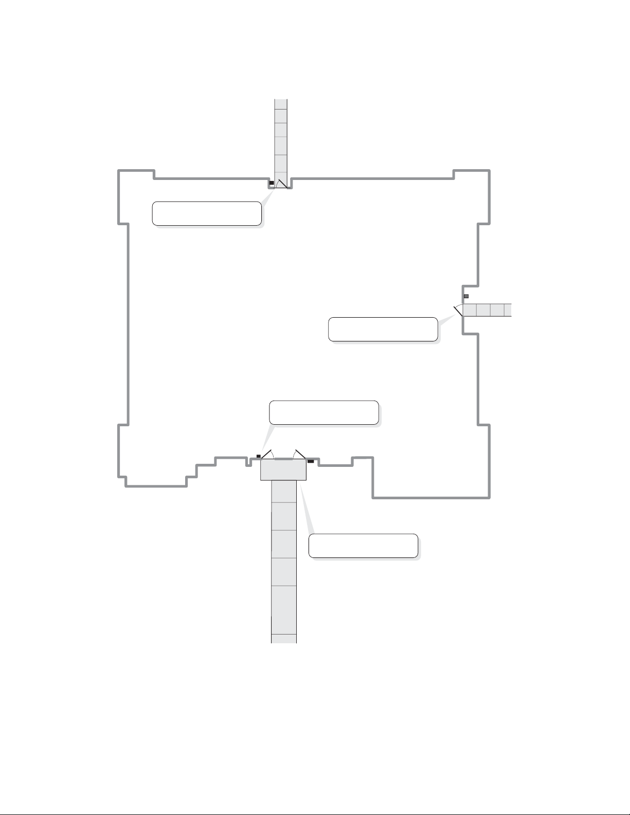
SAMPLE LAYOUT
Single Family Residence (NPB) Example
The unit can operate the vehicular gate with an access code or by remote control. It will allow Pedestrians entry with
an Access Card. It will also open the gate automatically for exiting cars.
Relay 3 - Strike Mode
Unlocks Pedestrian Gate
Wiegand Card Reader
(Pedestrian Gate)
Main Keypad
(Driveway)
Relay 4 - Alarm Mode
Signals an alarm pad
(REX) Exit Request
Relay 1 - Strike Mode
Opens Vehicular Gate
Gate Operator
(Driveway)
Relay 2 - Control Mode
Turns on Light
11
Page 13
SAMPLE LAYOUT
Multi-Resident Complex Example
The unit can control the property with a vehicular gate operator, access card or the unit’s keypad. Residents can use
programmed remote controls for the parking lot, access cards for the pool or a personal entry code for the main
entrance. The main entrance is equipped with a door sensor to alert management about inappropriate use. The exit
sensor will automatically open the gate for exiting cars.
Pool
Relay 3 - Strike Mode
Opens Pool Gate
Wiegand Card Reader
(Pool Gate)
Parking Lot
(REX) Exit Request
Gate Operator
(Vehicular Gate)
Relay 2 - Strike Mode
Opens Vehicular Gate
Relay 4 - Shunt Mode
Shunts Alarm for
Main Entrance
Manager's
Office
Relay 1 - Strike Mode
Opens Main Entrance
Main Keypad
(Front Door)
12
Page 14

YOUR SYSTEM LAYOUT
How your system has been wired is an important part of programming it. Write down your configuration. To help
visualize it, draw a map of it below. If you’re unsure of your setup, consult your dealer/installer for more information.
Door Stat 1
Connection
Door Stat 2
Connection
Door Stat 3
Connection
Door Stat 4
Connection
Door Sensor
and/or
Exit Device
Door Sensor
and/or
Exit Device
Door Sensor
and/or
Exit Device
Door Sensor
and/or
Exit Device
External Access Control Device(s) connected to aux boards(s)
(Default Internal Keypad)
____________________________________________________________________
Device 0
____________________________________________________________________
Device 1
____________________________________________________________________
Device 2
____________________________________________________________________
Device 3
____________________________________________________________________
Device 4
Relay Connections
_____________________________________________________________________
Relay 1
_____________________________________________________________________
Relay 2
_____________________________________________________________________
Relay 3
_____________________________________________________________________
Relay 4
13
Autocall
Device
Autocall
Device
Autocall
Device
Yes
No
Yes
No
Yes
No
Page 15
PROGRAMMING SINGLE UNIT OVERVIEW
PROGRAMMING BASICS
The units can be programmed 4 different ways:
1. Keypad: You may use the keypad on the front panel (next page).
2. Local/Remote DTMF Phone: You may use the keypad on a local or remote phone to program the system. The unit
responds to the DTMF signals generated by your touch-tone phone (next page).
3. Direct/Modem Connection to a PC: In order to program the units with a direct or modem connection, your PC
must be running LiftMaster’s Windows
more about Versa XS 4.0 software visit LiftMaster.com/SoftwareDownload.
4. EL2000SS Keypad with Display: On EL2000SS units with an LCD, you have two ways to use the LCD to program
the unit.
1. Enter program steps and use the LCD to confirm the step(s) before entry.
OR
2. Use the program menus in an interactive step-by-step manner to program common items in the system.
When using the program menus, you’ll notice that they are fairly intuitive and walk you through the common areas
necessary to set up a basic system. There is also a quick start menu selection, numerous help files and voice and text
confirmation of the areas programmed.
Two areas that do need special mention are noted below:
1. Scan Mode: This is a new feature that allows you to enter cards by scanning them into the system. The program
menus are the only area in the system where you can use the scan mode feature.
®
compatible Versa XS 4.0 software (not covered in this manual). To learn
2. and keys and and keys for navigation and text input while using the program menus. The
up and down keys help you to scroll through the alphabet for text input, while "4" and "6" numeric keys allow you
to advance the cursor forward or backward.
The best way to learn how to navigate through the menus is to actually use them to program the standard settings in
the system. See the keypad programming template below for a description of the keypad keys and functions.
EL2000SS LCD Programming Template
+HOS
CuUVRU
CurVRU
CuUVRU
A A B C
6HOHFW
Value
123
Ta b
123
Z A B C
Clear
123
NuPber
(QWHU
A B C TH[W
14
Page 16
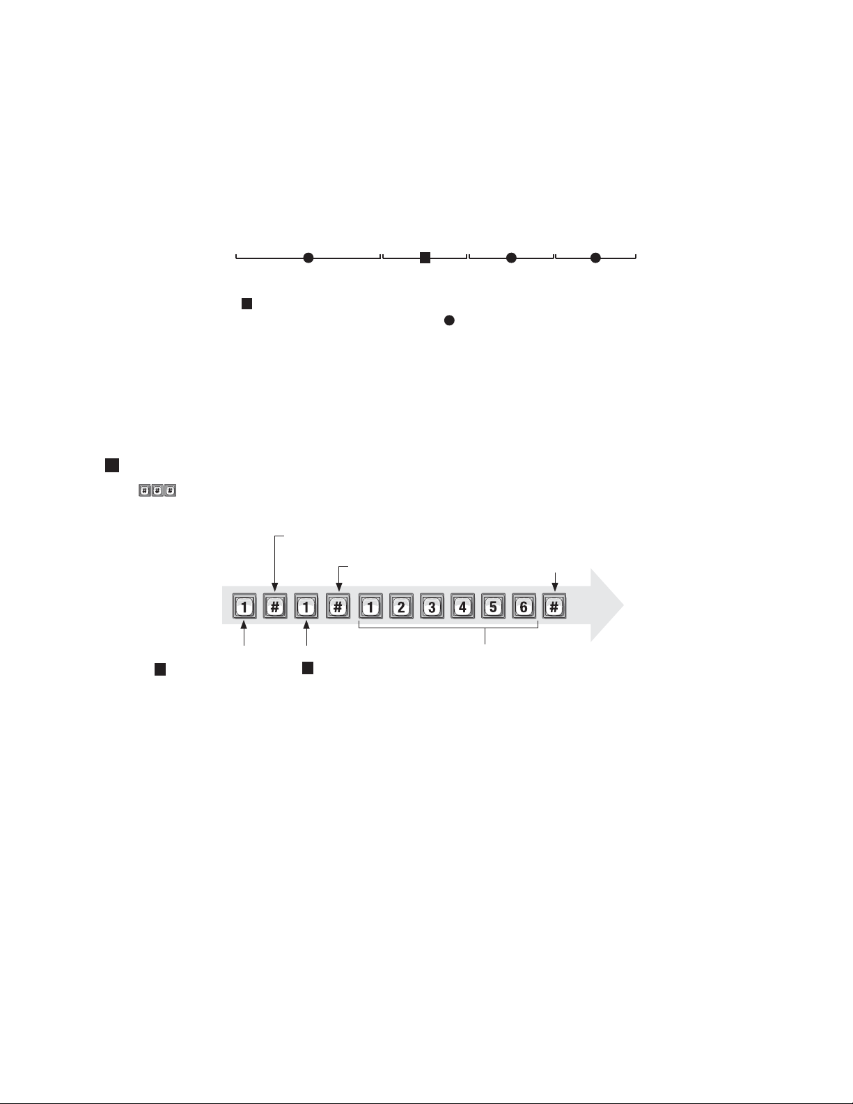
PROGRAMMING BASICS
Procedure Required to Program EL Models:
1. 1, 2 or 3 digit Programming Number. (See "Quick Reference Guide" Tables for descriptions and procedures.)
2. One or more Data Fields.
3. Pound Key (#) as a Data Field Separator and at the end of the programming sequence to Save the Data.
NOTES:
• All data fields must be separated with the pound key (#).
Example: (Programming Number) # (Data Field) # (Data Field) # (Data Field) #
1 3 42
Required Step Optional Step Required Step Required Step
• Steps tagged with a (
) are optional, press the pound key (#) to skip them. NOTE: Some steps are required and
must have data entered in them to continue, tagged with ( ).
• If you make an error during an entry, press the asterisk key (*) to cancel the step.
• When you correctly enter the entire programming sequence, the unit will respond with voice feedback (see also
System Feedback/Responses(Beeps) on page 17).
EXAMPLE OF A PROGRAMMING SEQUENCE:
1 "Changing the Password"
NOTE: must be pressed fi rst to enter programming mode.
First Pound Key:
Enter
Programming
Mode
(Next page)
Programming Number:
Changes or verifi es
1
the password.
Separates the fi rst fi eld.
Pound Key:
Separates the data fi eld.
Data Field:
Changes the password
1
(2 verifi es the password).
Data Field:
(The new password)
Last Pound Key:
Saves the data.
Voice
feedback
Exit
Programming
Mode
(Next page)
15
Page 17

ENTER PROGRAMMING MODE ***
If you will be programming the unit via modem, please refer to LiftMaster.com/SoftwareDownload.
IMPORTANT: After entering programming mode for the first time, we suggest you change the password to maintain
the security of your system (see page 51).
From the Keypad:
1
Press
2
Enter the six-digit password. The default is six zeroes. Voice Feedback
NOTE: If the unit is an EL2000SS, you may either follow the menu instructions, or enter "2", to manually enter
program steps.
From the Residence Telephone:
1
When you lift the receiver, press
NOTE: If multiple units are sharing the same phone line, then a Unit ID Code (1-7) will need to be entered at
this time. See page 20 for more information about Multiple Unit Sites.
2
Enter the six-digit password. The default is six zeroes.
3
Press and the audio tone will stop.
The unit is now ready to accept programming instructions!
From the Remote Telephone:
1
Dial the unit’s phone number:
NOTE: If the unit and an answering machine (or answering service) utilize the same phone line, let the line ring
at least two times, hang-up, and call back within one minute. The unit will answer on the second call. If the unit
does not answer, you may need to change the ring count (see page 53).
2
When the unit picks up the call, you will hear the audio message: "Please enter password"
3
Press
NOTE: If multiple units are sharing the same phone line, then a Unit ID Code (1-7) will need to be entered at
this time. See page 20 for more information about Multiple Unit Sites.
4
Enter the (6) six-digit password. The default is six zeroes.
5
Press and the audio will stop.
The unit is now ready to accept programming instructions!
EXIT PROGRAMMING MODE 0
• Press on the unit keypad and the unit will respond with audio feedback when disconnecting.
• Press on the telephone and the unit will respond with audio feedback when disconnecting.
Press when using a telephone or the unit to cancel programming sequence and exit programming mode.
16
Page 18

SYSTEM FEEDBACK / RESPONSES (BEEPS)
The units emit various audio tones to respond to input and to indicate certain conditions.
Programming Responses:
Voice Response Description
4 Short Beeps: Enter command System is waiting for a latch command by user with
entry code
3 Short Beeps: Exit program Exiting from program mode
2 Short Beeps: Valid step Valid step entered in programming mode
1 Long Beep: Invalid step Invalid step entered during programming
2 Long Beeps: Duplicate code Duplicate code entered during programming a new code
3 Long Beeps: Capacity reached The new code is rejected because database is full
1-7 Short Beeps: Unit 1-7 Give feedback of system ID number to user in
programming mode: keypad or phone
1 Short Beep: Digit Key name Echo each key press on user’s touch tone phone or key
press while in programming mode
Other Response:
Voice Response Description
4 Long Beeps: Chime System starts up
Visual Responses:
LED Status Description
Solid Red Idle power, door 1 is locked
Blinking Red Strikes and Out for door 1
Solid Green Granted access for door 1
Blinking Green Latch for door 1 is unlocked
17
Page 19

SYSTEM FEEDBACK / RESPONSES (BEEPS)
Direct Command Responses:
Voice Response Description
10 Short Beeps: Entrance 1-4 opened This is the command to latch open door 1
5 Short Beeps: Entrance 1-4 closed This is the command to keep the latch closed for
door 1
Visitor Responses:
Voice Response Description
10 Short Beeps: Access granted Access is granted from an entry code or other code
used on door 1. Access may also be granted by a
tenant on their touch tone phone. The voice is played
first then the beeps
1 Long Beep: Access denied Access is denied from an entry code, card code used
or invalid password on door 1. Access may also be
denied by a tenant on their touch tone phone
1 Long Beep: Invalid code Unknown entry or directory code on door 1
2 Short Beeps: --- Indicates door 1 is already open
Busy Tones: --- Directory code in DND mode or resident line is in use
1 Short Beep Per Second: --- 1 beep is played per second for remaining seconds
during a call
2 Short Beeps: Program mode System acknowledges valid prefix/password and is in
program mode
18
Page 20

SENDING DIRECT COMMANDS FROM THE RESIDENT’S PHONE
(NPB / Single Family Residence ONLY)
You can send commands directly to the unit from your phone without being in programming mode. This feature is
only available from a single-family residence or a manager who is sharing a phone line with the unit.
To Enter a Direct Command from a Residence Phone:
1
Lift the receiver and press
NOTE: If multiple units are sharing the same phone line, then a Unit ID Code (1-7) will need to be
entered at this time. See next page for more information about Multiple Unit Sites.
The unit is now ready to allow direct commands only!
EXAMPLE 1:
Enters direct command mode.
EXAMPLE 2:
Enters direct command mode for unit three.
19
Page 21
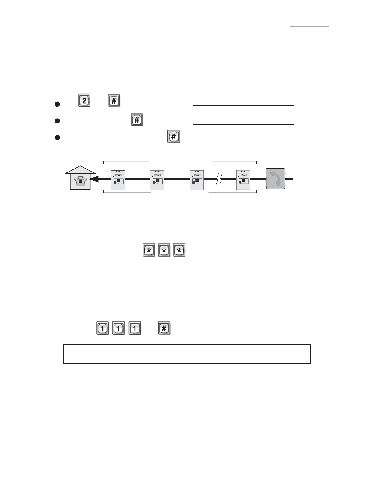
PROGRAMMING MULTIPLE UNITS OVERVIEW
Up to seven (7) units can be installed on a single telephone line. Each unit must have a "Unique Unit ID" number and
the "Number of Units in Chain" assigned to it.
Set the Unit ID Number and Number of Units in Chain: 2
The unit ID identifies each unit within a chain. Adding or removing will require the unit ID’s to be re-entered.
Factory Setting: Unit ID 1 and Number of Units in Chain 1.
1
Press Then
IMPORTANT: This must be performed
2
Unit ID Number (1-7), Then
3
Total Number of Units in Chain (1-7), Then
for EACH unit in the Chain.
EXAMPLE:
Residence
Unique Unit ID Sequencial Order
Number of
Units in Chain “7”
Unit ID “7”Unit ID “3”Unit ID “2”Unit ID “1”
Telco Entrance Box
Demarcation Point
IMPORTANT:
You must program each unit ID using the main keypad first before attempting remote access.
EACH unit in the Chain must have the same "Rings Before Unit Answers" 16.
Factory Setting - 5 Rings
EACH unit in the Chain must have the same "Alternate Prefix" 115.
Factory Setting - Normal (use
to enter programming)
Make sure the “Rings Before Unit Answers” value 16 is greater than “Maximum Rings Allowed Before Aborting
Attempt” value 14.
Verify Unit Number: 111
This allows you to verify a unit’s number within a chain. When you perform this step, the unit will respond with
the number corresponding to its unit ID number. The message two (2), for example, means the unit is number
2 in the chain.
Then
If you make an error during an entry, press the asterisk key (*) to begin again.
20
Page 22

SETUP “YOUR SETTINGS”
The units come preprogrammed with Factory Settings. When the unit is first installed, you DO NOT need to program
each feature. Review the unit’s factory settings before programming (see Quick Reference Guide, pages 4-8 for ALL
the Factory Settings).
GETTING STARTED
Change the Unit Password: 1
Recommended
Change the unit password to prevent any tampering with your system’s database. When changing
the password, save a copy of it in a secure location. If you lose the password, you will not be
able to enter into programming mode.
Factory Setting: 000000
See page 51.
Set the Clock: 3
Recommended
An accurate clock is critical to the proper use of schedules and for accurately reporting
transactions.
See page 47.
Change the Unit’s ID and Chain Number for
Multiple Unit Configurations ONLY:
Recommended
The Unit ID number identifies each unit within the chain. Setting the "Unit ID" and "Number of
Units in the Chain" are required so Versa XS can send or receive data to/from the correct units
within the chain.
2
Factory Setting: Unit ID Number "1" and Number of Units in Chain "1".
See previous page.
21
Page 23

SETUP EXTERNAL ACCESS CONTROL DEVICES
The unit must have all external access control device options configured into it, before many of the other
programming options can proceed. You must tell the unit "what it’s wired to" and "how you want the devices to
behave." To do this you must know what a "Door Number " is and what a "Relay" is.
What is a Door Number?
A Number (1-4) YOU assign to the unit to identify the External Access Control Devices wired to it. Up to 4
devices can be connected. Once identified, the unit will keep the Same Door Numbers in other programming.
The Internal Keypad is ALWAYS Assigned to Door Number 1.
What is a Relay?
A relay is a device that reacts to an electric current to activate other devices. Allowing the EL Model to lock or
unlock a door/gate, shunt (bypass) alarm contacts, or signal an alarm. The relays can be programmed to 4
different modes.
The 4 Modes of Operation are:
Strike Relay: A Strike Relay controls a door or gate by unlocking or opening it. It does not control any other
component associated with a system like Alarms, etc.
Shunt Relay: A Shunt Relay is normally wired to an alarm and works with strike relays to shunt (bypass) the
alarm when the door is opened with a valid access code. If the door is forced open, the system will not
shunt the alarm and the alarm will be triggered.
Alarm Relay: The Alarm Relay will activate another device, such as a siren, when 3 conditions occur. A door
is opened without a valid access code, a door is open past the allotted time programmed in, or too many
invalid codes are tried. Any of these will trigger the alarm relay.
Control Relay: The Control Relay can control another device such as an outdoor or indoor light near the
unit. For example, you could configure the system to turn on an entry light through a darkened area after a
resident enters a valid access code. The light would then turn off after a specified amount of time.
22
Page 24

Configuring "YOUR" Unit:
There are 3 sample configurations on pages 26 and 27 to help you understand the 4 step process needed
to setup YOUR external access control devices.
Step 1
Set Each Relay Mode for the Appropriate Response: There are 4 different relay modes (Previous
Page). The relay mode determines what the relay will control (a door, alarm, etc.). See next page.
Step 2
Set Each Relay’s Strike Time: The relay time determines the amount of time the relay remains
activated. For example, when a strike relay activates to unlock a door, the relay activation time
determines how long the door will remain unlocked (next page).
Step 3
Assign Each Door Number to One or More Relays: Defines which relays will activate when a
resident presents a valid access code to an external access control device (next page).
Assign Each External Access Control Device to a Door Number: When a valid access code is
Step 4
Step 1 Set Each "Relay Mode" to get the Appropriate Response:
entered into a external access control device, the Assigned door’s relays will activate (see below).
65
There are 4 different relay modes (see page 22). The Relay Mode determines what the response will be when a
valid access code is entered (open a door, turn on an alarm, turn on a light then turn it off, etc.). Be sure relays are
not activated when changing "Relay Mode" types.
Factory Setting: All Relays are Set at "1 - Strike"
1
Press
2
Enter the Relay Number (1-4). Then (#)
3
Enter Relay Mode (1, 2, 4, or 5). Then (#)
Then
1 = Strike - controls a door/gate by unlocking/opening it.
2 = Shunt - bypasses the alarm under normal
circumstances.
IMPORTANT: 1-3 must be performed for
EACH Relay assigned to the unit.
4 = Alarm - activates another device (siren).
5 = Control - controls another device
(on/off light).
EXAMPLE:
1 2 3
Assigns Relay "2" as a Shunt Relay
Step 2 Set Each Relay’s "Activation Time":
66
This is the amount of time (in seconds) the relay remains activated. This will define the amount of time a door
cycles (unlocks, then re-locks). Be sure relays are not activated when changing relay "Activation Time". Factory
Setting: All Relays are set at 10 seconds.
1
Press
Then
2
Enter the Relay Number (1-4). Then (#)
3
Enter Activation Time (1-300 Seconds). Then (#)
EXAMPLE:
1 2 3
When Activated, the Relay Number "4" will activate for "30" seconds.
NOTE: Most gate operators recommend activation of 2 seconds.
IMPORTANT: 1-3 must be performed for
EACH Relay assigned to the unit.
23
Page 25

Step 3 Assign "Each" Door Number to One or More Relays: 61
When a valid access code is used at an external access control device (Door), the unit can be set to activate one
or more relays. Factory Settings: Door 1 Activates Relay 1; Door 2 Activates Relay 2; Door 3 Activates
Relay 3; Door 4 Activates Relay 4
1
Press
2
Enter the Door Number (1-4). Then (#)
3
Enter Relays to be Activated (0000-1111). Then (#)
Then
IMPORTANT: 1-3 must be
performed for EACH Door Number
assigned to the unit.
0=Deactivate, 1=Activate (1st digit=Relay 4, 2nd digit=Relay 3, etc.)
Relay 4 Relay 3 Relay 2 Relay 1
EXAMPLE:
1 2 3
Deact Deact
Activate Activate
When a Resident uses a Valid Code at "Door 1", Relay "1" and Relay "2" will Activate
Step 4 Assign Each External Access Control Device a "Door Number": 60
To perform these 4 steps you MUST know EXACTLY where the External Access Control Device(s) are wired
in "Your" unit! When pages 13 and 23 are completed by you or your installer, they will help you
understand "Your" personal layout. If you do not know this, DO NOT PROCEED. Consult your Installer and/or
refer to the installation manual for assistance.
The units can be equipped with Wiegand reader and radio frequency (RF) modules that allow your system to
accommodate external access control devices such as a Wiegand-compatible card readers (keypad) and RF
receiver. In order for Wiegand devices to work successfully, you must assign them a "Door Number". When a
valid access codes is presented to the device, the Assigned Door’s Relays will activate. Factory Setting:
Main Keypad Device 1
Door 1 Door 1
Device 2
Door 2
Device 3
Door 3
Device 4
Door 4
IMPORTANT: 1-3 must be
performed for EACH external
1
Press Then
2
Enter External Access Control Device Number (1-4). Then (#)
access control device of unit.
Internal Keypad is ALWAYS Assigned to External Access Control Device Number 0.
3
Assign a Door Number (1-4) to the Device. Then (#)
NOTE: A "Door Number" is a number you
assign to each external access control
device. Only Wiegand devices may be
EXAMPLE A:
1 2 3
assigned to a door.
Device "1" is Assigned as Door "3".
EXAMPLE B:
1 2 3
Device "3" is Assigned as Door "4".
24
Page 26

“YOUR” DOOR SETTINGS
(See tables below for reference)
Device Location
Door
No.
Relay
Relay
Mode
Relay Function Relay Activation Time
(Seconds)
When “Your Door Settings” or “Door 1, 2, 3 or 4” are referenced throughout this manual, this completed chart will
outline how your unit will function.
SAMPLE: The System Controlling 1 Door (See next page for illustration)
Device Location Door No. Relay Relay Mode Relay Function Relay Activation Time (Seconds)
Main Keypad
Front Door Door 1
(REX) Exit Request
1 Strike Unlocks Door 10 sec.
2 Shunt
3 Alarm Sounds a Siren 10 sec.
4 Alarm Signals an Alarm Panel 10 sec.
Bypasses/Signals Alarm
40 sec.
SAMPLE: The System Controlling 2 Doors and a Vehicle Gate (See next page for illustration)
Device Location Door No. Relay Relay Mode Relay Function Relay Activation Time (Seconds)
Main Keypad and Postal Lock
Security Light
Wiegand Card Reader Back Door Door 2
Remote Control Buttons Gate Operator Door 3 4 Strike Opens Gate 10 sec.
Front Door Door 1
1 Strike Unlocks Door 10 sec.
2 Control Turns on Security Light 60 sec.
3 Strike Unlocks Door 10 sec.
SAMPLE: The System Controlling 4 Doors (See page 27 for illustration)
Device Location Door No. Relay Relay Mode Relay Function Relay Activation Time (Seconds)
Main Keypad Front Door (Entrance) Door 1 1 Strike Unlocks Door 10 sec.
Wiegand Keypad Front Door (Exit) Door 2 2 Strike Unlocks Door 10 sec.
Wiegand Card Reader Back Door Door 3
Wiegand Card Reader Manager’s Door Door 4 4 Strike Unlocks Door 10 sec.
3 Strike Unlocks Door 10 sec.
SAMPLE: The System Controlling Single Family Residence (See page 11 for illustration)
Device Location Door No. Relay Relay Mode Relay Function Relay Activation Time (Seconds)
Main Keypad and
(REX) Exit Request
Wiegand Card Reader Pedestrian Gate Door 2
Alarm In EL Unit Door 3 4 Alarm Signals an Alarm Panel 10 sec.
Driveway Door 1
1 Strike Opens Vehicular Gate 10 sec.
2 Control Turns on Security Light 10 sec.
3 Strike Unlocks Pedestrian Gate 10 sec.
SAMPLE: The System Controlling Multi-Resident Apartment (See page 12 for illustration)
Device Location Door No. Relay Relay Mode Relay Function Relay Activation Time (Seconds)
Main Keypad Front Door Door 1 1 Strike Unlocks Door 10 sec.
Remote Control and
(REX) Exit Request
Wiegand Card Reader Pool Gate Door 3
Siren Front Door Door 4 4 Shunt Bypasses/Signals Alarm 30 sec.
Vehicular Gate Door 2
2 Strike
3 Strike Unlocks Door 10 sec.
Unlocks Door
10 sec.
25
Page 27

UNIT CONTROLLING 1 DOOR
Relay 3 - Alarm Mode
Sounds siren for 10 sec.
Relay 1 - Strike Mode
Unlocks door for 10 sec.
Relay 2 - Shunt Mode
Bypasses/Signals alarm
for maglock for 40 sec.
Relay 4 - Alarm Mode
Signals an alarm
monitoring panel
REX Device
(Exit)
Main Keypad
(Front Door)
UNIT CONTROLLING 2 DOORS AND VEHICLE GATE
Wiegand Card Reader
(Back Door)
Relay 3 - Strike Mode
Unlocks door for 10 sec.
Relay 1 - Strike Mode
Unlocks door for 10 sec.
Relay 2 - Control Mode
Turns on security light
for 60 sec.
Main Keypad
(Front Door)
Postal Lock
Remote Control
(Gate Operator)
26
Relay 4 - Strike Mode
Opens Gate for 10 sec.
Page 28
UNIT CONTROLLING 4 DOORS
Wiegand Card Reader
(Back Door)
Relay 3 - Strike Mode
Unlocks door for 10 sec.
Wiegand Card Reader
(Manager's Door)
Relay 4 - Strike Mode
Unlocks Door for 10 sec.
Wiegand Keypad (Exit)
Relay 2 - Strike Mode
Unlocks Door for 10 sec.
Exit
Enter
Main Keypad
(Front Door)
Relay 1 - Strike Mode
Unlocks Door for 10 sec.
27
Page 29
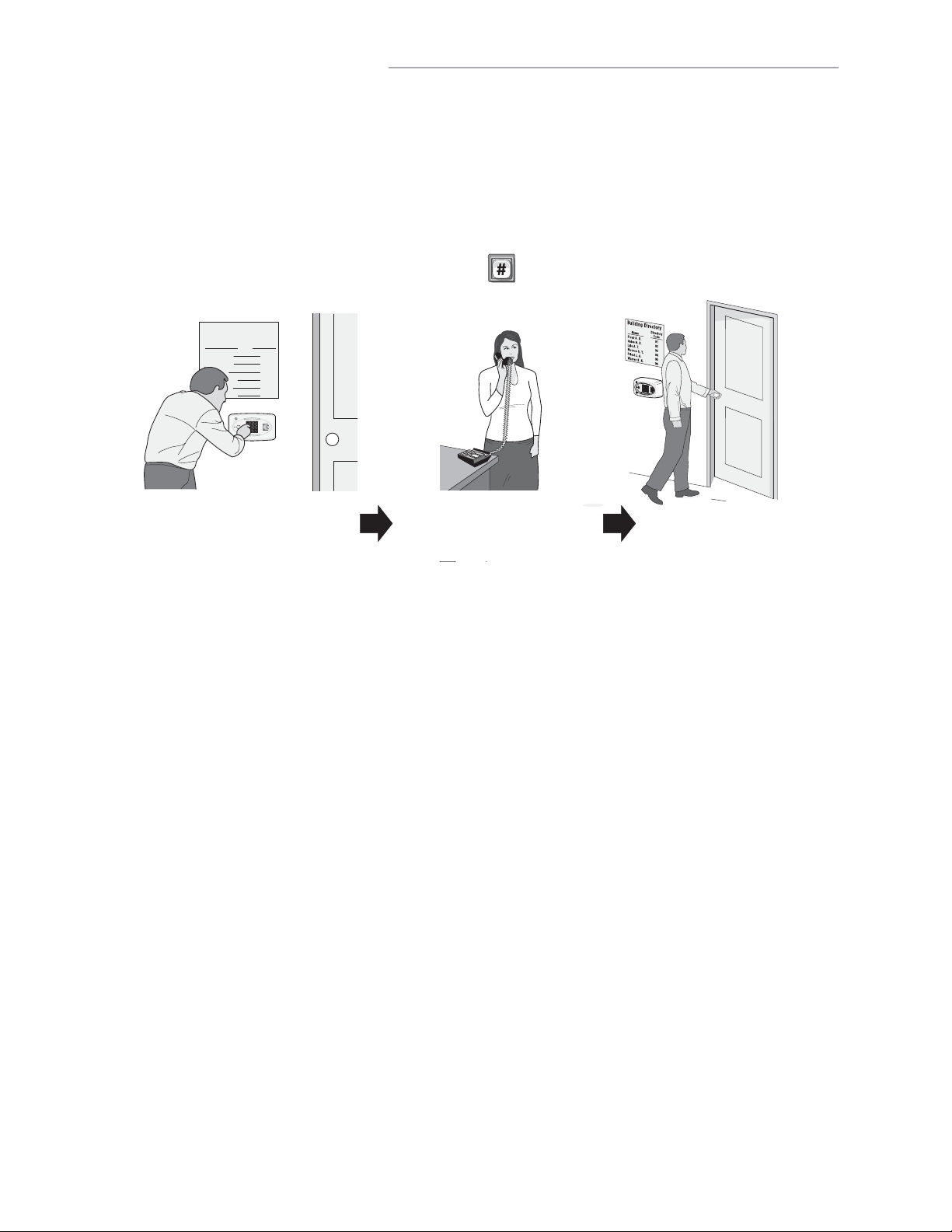
DIRECTORY CODES
ABOUT DIRECTORY CODES
Directory Codes are unique 1-4 digit codes that dial a corresponding telephone number in the building. When a
visitor wishes to contact a resident, the visitor enters the Directory Code on the unit’s keypad. The unit will dial the
phone number assigned to the code. The resident can then talk to the visitor by phone and grant them entry into the
building.
To Use an Existing Directory Code to Contact a Resident:
Enter the Directory Code on the unit’s keypad then press .
Building Directory
Floyd A. D.
Gates H. B.
Lyle A. T.
Monroe S. Y.
Priest J. A.
Warren B. K.
Visitor uses directory code to contact resident Resident can grant access to visitor Visitor gains entry
Name
Directory
Code
01
02
03
04
05
06
Before adding or modifying Directory Codes, answer the following questions:
• Have you chosen the Directory Code number you will assign? This number will be assigned to a resident.
The visitor will enter this number on the unit keypad to prompt the system to dial the resident’s phone
number.
• Do you know the resident’s phone number? The system needs the phone number so it can dial the resident
when prompted. If the resident’s phone has an extension, the unit will need that data as well.
• Will the resident want a Do Not Disturb schedule? If the resident doesn’t want to be disturbed during
certain times, you can configure his/her Directory Code with a Do Not Disturb schedule. During this
schedule, visitors won’t be able to call the resident. See page 31.
• Will the resident utilize a Call Forwarding number during certain times? Perhaps the manager of an
apartment complex wants the leasing office phone number forwarded to an answering service after 5pm on
weekdays and all day on weekends. See page 31 for more information.
• Will you activate or deactivate the Directory Code at a certain day and time? You may assign a Directory
Code to a resident and delay its use until a day and time you specify. Also you can deactivate the Directory
Code on a specified day and time. See page 32.
• For units with an LCD display, you can control how the tenant’s name is displayed on the screen. See page
33.
28
Page 30

SET DIRECTORY CODE LENGTH:
6
Factory Setting: 3
1
Press Then
2
Enter New Directory Code Length (1-4). Then (#)
EXAMPLE:
1 2
Makes Directory Code length 2-digit maximum.
IMPORTANT: You will not be able to decrease the Directory Code length if codes already exist that are more than
the attempted decrease length. For example, you will not be able to decrease a code from 2 digits to 1 digit if
2-digit codes already exist.
You will not be able to increase Directory Code length if there’s an entry code length conflict.
If you increase the Directory Code length, all existing codes will increase with leading zeroes for every digit
increase. For example, if you increase the length to 2 digits, an existing Directory Code of “4” will now be “04”.
ADD, EDIT OR DELETE DIRECTORY CODES
When adding or editing Directory Codes, note the following:
• Keep a record of each Directory Code you assign; in particular, write down the resident names associated
with each code. This will help when adding, editing, or deleting Directory Codes later.
• Each assigned Directory Code must be entered with the set amount of allowable digits (up to 4). For
example, if you assign "2" as a resident’s Directory Code, but the system is set for two digits, the visitor will
have to enter "02" to call the resident.
Add Basic Directory Code: 40
Add a Directory Code, Phone Number, and Phone Extension.
1
Press
2
Enter Directory Code (up to 4 digits). Then (#).
3
Enter Phone Number (up to 20 digits). Then (#).
3A
Phone Extension if necessary (up to 5 digits). Then (#).
EXAMPLE
Adds Directory Code "12" with phone number "555-8978". The phone extension field was skipped.
Then
:
1 2
3
3A
NOTE: A basic Directory Code will be active, have a do not disturb schedule of "0" (i.e., resident can be called
24 hours a day, 7 days a week), and have no call forwarding.
29
Page 31

Add or Edit Full Function Directory Code: 41
When adding a full function Directory Code, it will default as "active". To deactivate a code, or deactivate on a
specific time and date, see Activate or Deactivate a Directory Code on page 32.
1
Press
2
Enter Directory Code (up to 2 digits). Then (#)
3
Enter Phone Number (up to 20 digits). Then (#)
4
Enter Phone Extension (up to 5 digits). Then (#)
5
Enter Do Not Disturb Schedule (0-63). Then (#)
Then
0=May always be disturbed
1=Never disturb
6
Enable (1) or Disable (0) Call Forwarding. Then (#)
7
Enter Call Forward Schedule (0-63). Then (#)
0=Never Use Call Forward Number.
1=Use Call Forward Number.
8
Only Enter New Call Forward Phone Number (up to 20
digits). Then (#)
(Skip this step to keep existing Call Forward Phone
Number.)
8A
Enter Call Forward Phone Extension
(up to 5 digits). Then (#)
(If using an extension the unit MUST have a
phone number.)
Factory
Settings
Do Not Disturb Schedule = 0
Call Forwarding Enable or Disable = 0
Call Forwarding Schedule = 0
EXAMPLE:
1
2
3
4 5 6 7 88A
Adds Directory Code "45" with phone number "555-2134", phone extension "432", uses Do Not
Disturb schedule 2 and disables call forwarding.
Change a Directory Code ONLY: 44
Allows you to change ONLY the Directory Code without affecting the other data associated with the record (e.g.,
phone number, do not disturb schedule, etc.).
1
Press
2
The New Directory Code Number (Up to 4 digits). Then (#)
3
The Current Directory Code number (Up to 4 digits). Then (#)
Then
EXAMPLE:
1 2 3
Changes Directory Code from "14" to "23".
Delete a Directory Code: 48
1
Press
2
Enter the Directory Code number to be deleted (Up to 4 digits). Then (#)
Then
EXAMPLE:
1 2
Deletes Directory Code "23".
30
Page 32

DELETE ALL DIRECTORY CODES: 201
This will delete ALL Directory Codes from unit.
IMPORTANT: Once you delete the Directory Codes, you cannot retrieve them unless they are saved in
Versa XS 4.0.
1
Press
2
Enter
Then
Then
ENABLE OR DISABLE DO NOT DISTURB SCHEDULE: 10
Do Not Disturb (DnD) Schedules prevent visitors from calling residents during specified time frames. To assign a
DnD Schedule to a Directory Code, use the programming step for adding/editing a full function Directory Code
(see page 30). When enabling/disabling DnD Schedule for a Directory Code, the system will remember the
schedule assigned to the code. Factory Setting: Disabled
1
Press Then
2
Enter the Directory Code to be enabled or disabled. Then (#)
3
Enable (1) or Disable (0). Then (#)
EXAMPLE:
1 2 3
Disables the Do Not Disturb schedule for Directory Code "34".
ENABLE OR DISABLE CALL FORWARDING (DIRECTORY CALLS): 46
Call Forwarding redirects visitor calls to another telephone number instead of the regular phone number.
During a Call Forwarding call, the visitor will hear normal telephone line sounds but will not hear the number
being dialed. You can Enable or Disable the Call Forwarding Feature for a specific Directory Code (Dial-Out).
Factory Setting: Disabled
1
Press
2
Enter Directory Code (1-4 digits). Then (#).
3
Enable (1) or Disable (0). Call Forwarding. Then (#).
4
Enter Call Forward Schedule (0-63). Then (#)
Then
0 = Never Use Call Forward Number
1 = Use Call Forward Number
Factory
Settings
Call Forwarding Enable or Disable = 0
Call Forwarding Schedule = 0
5
Only Enter New Call Forward Phone Number (up
to 20 digits). Then (#) (Skip this step to keep
existing Call Forward Phone Number.)
5A
Enter Call Forward Phone Extension (up to 5
digits). Then (#) (If using an extension the
unit MUST have a phone number.)
EXAMPLE:
1 2
3 4 5 5A
Enables Call Forwarding number 555-3662 for Directory Code "14" with a use schedule of "2".
31
Page 33

ADD / MODIFY RESIDENT DND AND/OR CALL FORWARDING: 49
Add/Modify DnD and Call Forwarding Information for the Resident (NPB) or manager. Do Not Disturb (DnD)
Schedules prevent visitors from calling the Resident (NPB) or manager phone during specified time frames. Call
Forwarding redirects visitor calls to an outside telephone number instead of ringing the Resident (NPB) or
manager phone. During a Call Forwarding call, the visitor will hear normal telephone line sounds but will not hear
the number being dialed. You can Enable or Disable, individually, the DnD and Call Forwarding features for the
Resident (NPB) or manager phone.
Control Setting is Disabled.
1
Press
2
Set DnD Control Setting, Enabled (1) or Disabled
(0). Then (#).
3
Enter Do Not Disturb Schedule (0-63). Then (#).
4
Set Call Forward Control Setting, Enabled (1) or
Disabled (0). Then (#)
5
Enter Call Forward Schedule (0-63).Then (#)
EXAMPLE:
Then
Factory Setting: DnD Control Setting is Disabled (0); Call Forwarding
6
Only Enter New Call Forward Phone Number (up to 20
digits). Then (#) (Skip this step to keep existing Call
Forward Phone Number.)
6A
Enter Call Forward Phone Extension (up to 5
digits). Then (#) (If using an extension the unit
MUST have a phone number.)
7
Enter Call Forward Extension Delay (0-30 sec.). Then (#)
1
76A65432
The DnD Control Setting is Enabled and uses Schedule "34". It also Enables Call Forwarding
which uses Schedule "22". Call Forwarding uses Phone Number "976-5000" with Extension
"1136" and waits "20" seconds before dialing the Extension.
ACTIVATE OR DEACTIVATE A DIRECTORY CODE: 45
Activate or deactivate Directory Codes. Also activate or deactivate specific dates and times for those Directory
Codes.
Activate / Deactivate a Directory Code:
Disabling the Activate Directory Code
Activate Directory Code 3, then the four If statements could apply:
1. If you disable the Start Activation Date 4 and disable the End Deactivation Date 5 and omit all dates and
times, the Directory Code will immediately become active and stay that way until the code is deactivated or
deleted.
2. If you enable the Start Activation Date 4 and add only a "Start Date and Time" 4A 4B and disable the End
Deactivation Date 5, the Directory Code will activate on that "Start Date and Time".
3. If you disable the Start Activation Date 4 and enable the End Deactivation Date 5 and add only an "End Date
and Time"
5A 5B
, the Directory Code will deactivate on that "End Date and Time".
4. If you enable the Start Activation Date
Date 5 and add an "End Date and Time" 5A 5B, the Directory Code will activate on that "Start Date and Time"
and deactivate on the "End Date and Time".
To Activate or Deactivate a Directory Code:
1
Press Then
2
Enter Directory Code (1-4 digits). Then (#)
3
Activate Directory Code, (Enable-1 or Disable-0). Then (#)
4
Use Start Activation Date, (Enable-1 or Disable-0). Then (#)
4A
Start Date (yymmdd). Then (#)
4B
Start Time (hhmm). Then (#)
3
, the Directory Code will always be deactivated. If you enable the
4
and add a "Start Date and Time" 4A 4B enable the End Deactivation
5
Use End Deactivation Date, (Enable-1 or
Disable-0). Then (#)
5A
End Date (yymmdd). Then (#)
5B
End Time (hhmm). Then (#)
NOTE: All time must be entered using a 24-hour
format (8am=0800, 3pm=1500 etc.).
EXAMPLE:
1 2 3
Year Month Day
4
4A
24-Hour Time
4B
Directory Code "33" is activated on February 1st, 2016 at 6pm.
32
5
5B
5A
Page 34

DIRECTORY CODE DISPLAY OPTION: 141
Directory Code must exist in the unit’s database. Factory Setting: 0, 1, 2 or 3
1
Press Then
2
Enter Directory Code. Then (#)
3
Enter Hidden Attribute Option (0-3). Then (#)
Option 0 = Show All (always show name and directory code number).
Option 1 = Show Name (only shows name on the tenant list in the display).
Option 2 = Show Code (only shows the code on the tenant list in the display).
Option 3 = Hide (does not show the name or the code in the tenant list-tenant is skipped in the display).
RESIDENT DISPLAY OPTION: 141
To modify how the resident is displayed use Step 141, however skip entering the directory code. Also, note that
only options 1 and 3 are allowed, because the resident does not have a directory code. Factory Setting: 1
1
Press Then
2
Press (#)
3
Enter Hidden Attribute Option (1 or 3). Then (#)
Option 1 = Show Name (only shows name on the tenant list in the display).
Option 3 = Hide (does not show the name or the code in the tenant list-tenant is skipped in the display).
VERIFY DIRECTORY CODE: 47
This program Step displays the phone number and relay assignment information in the LCD screen. It’s available in
EL25 and EL2000SS systems but it should only be used in EL2000SS systems (with display). The sequence after
getting in the programming modes section is 47#directory code# (e.g.47#001#).
1
Press Then
2
Enter the Directory Code number (Up to 4 digits). Then (#)
33
Page 35

ENTRY CODES
ABOUT ENTRY CODES
Entry Codes are programmable, numeric codes (3-9 digits in length) that allow entry or exit through a gate/door.
Residents enter their assigned entry code onto the unit’s keypad to prompt the system to grant access.
To use an existing Entry Code:
On the unit’s keypad, enter the assigned "Entry Code". If you make a mistake entering the code, press .
Resident keys in personal Entry Code Grants Entry
Before adding or modifying Entry Codes answer the following questions:
• Have you chosen the Entry Code number you will assign? This number will be assigned to a resident. The
resident will enter this number on the unit of the keypad to prompt the system to grant access.
• Will the Entry Code have a use schedule (a.k.a. Time Zone)? You may assign a schedule to an Entry Code
so that it is valid only during specified time frames.
• What schedules will the Entry Code use at each door? You may assign a schedule at each door that a
resident may enter through.
• Will an entry code be used for a pre-defined number of uses? You can assign a utility option to control the
number of uses for an entry code.
• Will the entry code use action codes? You may assign special use on an entry code. Special use entry
codes execute an action at the main keypad.
34
Page 36

SET AN ENTRY CODE LENGTH: 7
Factory Setting: 4 Digits
1
Press Then
2
Enter New Entry Code length (3-9 digits). Then (#)
EXAMPLE:
1 2
Makes Entry code length 5 digit maximum.
IMPORTANT: You will not be able to decrease the Entry Code length if codes already exist that are more than the
attempted decrease length. For example, you will not be able to decrease a code from 5-digits to 4-digits if 5-digit
codes already exist.
If you increase the Entry Code length, all existing codes will increase with leading zeroes for every digit increase.
For example, if you increase the length to 5 digits, an existing Entry Code of "4556" will now be "04556". This value
correlates with directory code length. The Entry Code length must always be one (1) digit greater than the
directory code length.
You will not be able to decrease the Entry Code length if it conflicts with the Directory Code length.
ADD, EDIT OR DELETE ENTRY CODES
When adding or editing entry codes, note the following:
• Keep a record of each Entry Code you assign. In particular, write down the resident names associated with
each code. This will help when adding, editing or deleting Entry Codes later.
• Each assigned Entry Code must be entered with the set amount of allowable digits (3-9). For example, if
you assign "4578" as a resident’s Entry Code, but the system is set for 5 digits, the visitor will have to enter
"04578" to enter the building.
Add a Basic Entry Code: 50
Add an Entry Code ONLY. For adding or editing full function Entry Codes (i.e., codes with additional options such
as use schedules, door assignments, etc.). See next page.
1
Press Then
2
Enter Entry Code (3-9 digits). Then (#)
EXAMPLE:
Adds Entry Code "5400".
NOTE: Factory Setting for Entry Code Length is
4 digits (see "Entry Code Length" above).
21
NOTE: A basic Entry Code will be active and unlock all controlled doors, with no time constraint (i.e., can be used
24 hours a day, 7 days a week).
35
Page 37

Add or Edit Full Function Entry Code: 51
When adding a full Function Entry Code, it will default to "Active" at the current date and time with no
deactivation date. To deactivate a code, or to activate or deactivate on a specific time and date, see Activate or
Deactivate Entry Code on page 38.
5
1
Press Then
2
Enter Entry Code (3-9 digits). Then (#)
3
Schedule for Door 1 (0 to 63). Then (#)
0=Full Restrictions 1=Full Access
4
Schedule for Door 2 (0 to 63). Then (#)
0=Full Restrictions 1=Full Access
Schedule for Door 3 (0 to 63). Then (#)
0=Full Restrictions 1=Full Access
6
Schedule for Door 4 (0 to 63). Then (#)
0=Full Restrictions 1=Full Access
Factory Settings: All Doors = 1 Full Access
EXAMPLE:
1 2
3 4 5 6
Door 3Door 2Door 1 Door 4
Enables entry code "5400" to activate doors 1 and 2 on schedule #2 and restricts access to
doors 3 and 4.
Change Entry Code ONLY: 54
Change only the Entry Code without affecting the other data associated with the code (e.g., schedule, door
assignment, etc.). For example, you change only the code and keep the resident’s existing schedule and door
assignment because unauthorized individuals have been using that resident’s code.
1
Press Then
2
The Current Entry Code Number (3-9). Then (#)
3
The New Entry Code Number (3-9). Then (#)
EXAMPLE
:
1 2 3
Changes entry code from "6543" to "3456".
Delete an Entry Code: 57
1
Press Then
2
Enter the Entry Code number to be deleted (3-9 digits). Then (#)
Change Entry Code Door Access: 75
Change which doors or single door an entry code activates. By default new entry codes can open any door, use
this step to have the code open a specific door.
1
Press Then
2
Enter the Entry Code number (3-9 digits). Then (#)
3
Enter 0 for access at any door. Enter 1,2,3 or 4 for specific door access.
If you make an error during an entry, press the asterisk key (*) to begin again.
36
Page 38

Assign Utility Option: 58
Assign a limited use entry code. This feature allows the user to assign a fixed number of uses for an entry code.
The number of uses may reset daily or weekly. For example, allow a temporary code use 4 times a day. Use the
never reset option to give a fixed use until all tries are used up. Factory Setting: Off
1
Press Then
2
Enter new or existing entry code (3-9). Then (#)
3
Option:
0 = Off
1 = Reset use daily at midnight
2 = Reset weekly
3 = Never reset
4
Number of uses (1-15)
EXAMPLE:
89
1 2
3
4
Entry Code "1394" has 1 use resetting weekly for direct commands from the keypad.
Assign Special Use Entry Code at the Unit Keypad: 59
Table of responses for Action Codes: Voice is the primary response, if there is no voice then beeps are played.
When you hold down the last digit, you will hear "command" and then you enter one of the command numbers.
Command Number Action
0 Release all Doors and return to previous schedule
1 Toggle Open/Close for Door 1
2 Toggle Open/Close for Door 2
3 Toggle Open/Close for Door 3
4 Toggle Open/Close for Door 4
5 Toggle Enable/Disable Resident Call Forward
6 Toggle Enable/Disable Resident Do Not Disturb
7 Get Door Status (Rolling). Each use reports status of next door. For example used
once the status may report door 1, used again then status reports door 2, etc.
* The Open status means the door is currently opened by a Latch Command or in the Unlock portion of an
Automatic Schedule.
** The commands 5 and 6 play a single short beep when enabled or a single long beep when disabled.
1
Press Then
2
Enter existing entry code (3-9) and hold down last digit for command prompts. Then (#)
3
Enable/Disable special use. Then (enable = 1, disable = 0) (#)
EXAMPLE:
99
1 2
3
Entry Code "1394" has the ability to execute an action at the main keypad.
NOTE: You may not assign utility codes with special use ability. When you hold down the last digit, you will hear
"command" and then you enter one of the command numbers.
37
Page 39

Delete ALL Entry Codes: 202
This will delete ALL Entry Codes from unit.
IMPORTANT: Once you delete the Entry Codes, you cannot retrieve them unless they are saved in Versa XS 4.0.
1
Press Then
2
Enter Then
ACTIVATE OR DEACTIVATE AN ENTRY CODE: 56
This allows you to activate or deactivate an Entry Code, also on a specific date and time.
Activate / Deactivate an Entry Code:
Disabling the Activate Entry Code
3
, then the four If statements could apply:
1. If you disable the Start Activation Date 4 and disable the End Deactivation Date 5 and omit all dates and times, the
Entry Code will immediately become active and stay that way until the code is deactivated or deleted.
2. If you enable the Start Activation Date 4 and add only a "Start Date and Time" 4A 4B and disable the End
Deactivation Date 5, the Entry Code will activate on that "Start Date and Time".
3. If you disable the Start Activation Date 4 and enable the End Deactivation Date 5 and add only an "End Date and
Time" 5A 5B, the Entry Code will deactivate on that "End Date and Time".
4. If you enable the Start Activation Date 4 and add a "Start Date and Time" 4A 4B enable the End Deactivation Date 5
and add an "End Date and Time" 5A 5B, the Entry Code will activate on that "Start Date and Time" and deactivate on
the "End Date and Time".
3
, the Entry Code will always be deactivated. If you enable the Activate Entry Code
To Activate or Deactivate an Entry Code:
1
Press Then
2
Enter Entry Code (3-9 digits). Then (#)
3
Activate Entry Code, (Enable-1 or Disable-0).
Then (#)
4
Use Start Activation Date, (Enable-1 or Disable-0).
Then (#)
VERIFY AN ENTRY CODE: 55
Verify that an Entry Code exists in the unit’s database.
Audio Feedback "Invalid Step": Indicates the code Does Not exist in the database.
Audio Feedback "Valid Step": Indicates the code Exists in the database.
1
Press Then
2
Enter Entry Code (3-9 digits). Then (#)
4A
Start Date (yymmdd). Then (#)
4B Start Time (hhmm). Then (#)
5
Use End Deactivation Date, (Enable-1 or
Disable-0). Then (#)
5A End Date (yymmdd). Then (#)
5A End Time (hhmm). Then (#)
NOTE: All time must be entered using a
24-hour format (8am=0800, 3pm=1500 etc.).
If you make an error during an entry, press the asterisk key (*) to begin again.
38
Page 40

ACCESS CARDS
ABOUT CARDS
Access cards allow entry or exit through a gate/door. This feature allows residents to swipe a card into a card reader
(other card types and card readers may apply) to prompt the system to grant access.
Resident uses Card Reader Grants entry
Before adding or modifying cards, answer the following questions:
• Do you know the card’s number? Each card will have a pre-defined number. You must enter the card’s
number into the system when assigning a card.
• Do you know each card type you will assign? The system must know the type of card that will be used (e.g.,
Standard 26-bit or Sentex 30-bit). You may assign a default card type if all of your cards are the same type
(see also page 43). If you don’t know the card type, check with the card manufacturer or your installing dealer.
• Do the cards have a Facility Code? These codes allow cards to be associated with a facility or complex. This
feature is useful if you manage more than one complex. You may also assign a default facility code if a group
of cards will share the same code (see also page 43).
NOTE: Cards may have the same card code as long as their Facility Codes differ and/or the cards are a different
type.
• What schedules will the card use at each door? You may assign a schedule to each door that a card may
enter through.
39
Page 41

ADD, EDIT OR DELETE CARDS
When adding or editing cards, note the following:
• Card codes depend on type: 1-65535 (26 or 30-bit).
• If you don’t add a facility code or card type, the system will assign the default (see page 43).
The allowable facility code range is 0-255 for 26-bit cards or 0-63 for 30-bit cards.
• When entering cards with facility codes:
- Enter the facility codes individually when adding cards OR
- Enter a default facility code. If you don’t, the card will be assigned the default facility code (refer to page 43).
Change Card Code Door Access: 78
Change which doors or single door a card code activates. By default new card codes can open any door, use
this step to have the code open a specific door.
1
Press Then
2
Enter Card Number (1-65534 [26 or 30-bit]). Then (#)
3
Enter Facility Code (0-63 [30-bit], 0-255 [26-bit]). Then (#)
4
Enter Card Type (26 or 30). Then (#)
5
Enter 0 for access at any door. Enter 1,2,3 or 4 for specific door access.
Add a Basic Card: 80
This programming step allows you to add a card using the card’s number. For adding or editing full function
cards (i.e., cards with additional options such as use schedules, door assignments, etc.) see next section down.
NOTE: This step must be repeated for each card.
1
Press Then
2
Enter Card Number (1-65534 [26 or 30-bit]). Then (#)
3
Enter Facility Code (0-63 [30-bit], 0-255 [26-bit]). Then (#)
4
Enter Card Type (26 or 30). Then (#)
EXAMPLE:
1 2
3
Adds card with number "34432", default Facility Code and 30-bit Card Type.
NOTE: A basic card will be active with the current system time and never deactivate, unlock all doors connected
to the EL Models, with no time constraint (i.e., can be used 24 hours a day, 7 days a week).
For new cards, if you don’t add a Facility Code or Card Type, the system will add the defined default values. For
details, see Default Facility Code or Default Card Type on page 43.
4
40
Page 42

Add or Edit a Full Function Card: 81
When adding a full function card, it will default as "Active". To deactivate a code, or deactivate on a specific time
and date, see Activate or Deactivate Card on page 42.
1
Press Then
6
Schedule for Door 2 (0-63). Then (#)
0=Full Restrictions 1=Full Access
2
Enter Card Number (1-65534 [26 or 30-bit]).
Then (#)
3
Enter Facility Code (0-63 [30-bit],
0-255 [26-bit]). Then (#)
4
Enter Card Type (26 or 30). Then (#)
5
Schedule for Door 1 (0-63). Then (#)
7
Schedule for Door 3 (0-63). Then (#)
0=Full Restrictions 1=Full Access
8
Schedule for Door 4 (0-63). Then (#)
0=Full Restrictions 1=Full Access
Factory Settings: All Doors = 1 Full Access
0=Full Restrictions 1=Full Access
EXAMPLE:
21
3 4 5 6 7 8
Door 2Door 1 Door 3 Door 4
Adds card with number "12287", Facility Code "1", 30-bit Card Type, schedule "2", that opens
door 1 ONLY.
NOTES:
• For new cards, if you don’t add a Facility Code or Card Type, the system will add the defined default values. For
details, see Default Facility Code or Default Card Type on page 43.
• To replace a lost card first delete the lost card (Step 88 on page 42) and then add the new card to the unit’s
database (Step 81 on this page).
• The new card uses the default settings for active and inactive values. To modify these settings use Step 87 on
page 42.
Add a Group of Cards at Once: 82
This feature allows you to enter a large number of cards into the system at one time. Individual cards from a
group can be edited later. For example, you have 250 cards that you want to enter into the system so that every
time someone needs a card, you won’t have to program the system individually to enter a new card.
1
Press Then
7
Schedule for Door 1 (0 to 63). Then (#)
0=Full Restrictions 1=Full Access
2
Enter Card Number (1-65534 [26 or 30-bit]).
Then (#)
3
Enter Ending Card Number (1-65534 [26 or
30-bit]). Then (#)
4
Enter Facility Code (0-63 [30-bit],
0-255 [26-bit]). Then (#)
5
Card Type (26 or 30). Then (#)
6
Activate (1) or Deactivate (0). Then (#)
8
Schedule for Door 2 (0 to 63). Then (#)
0=Full Restrictions 1=Full Access
9
Schedule for Door 3 (0 to 63). Then (#)
0=Full Restrictions 1=Full Access
10
Schedule for Door 4 (0 to 63). Then (#)
0=Full Restrictions 1=Full Access
Factory Settings: All Doors = 1 Full Access
EXAMPLE:
c A
d
1 2 4 5 6 7 8 9 103
Adds a inactive group of Cards that range between "21500" and "21600", default Facility Code,
30-bit Card Type, inactive, and valid at all doors.
NOTES:
• Group cards must be the same Card Type and have the same Facility Code. In addition, you may also activate
the cards, add a schedule to one or more doors. These options must also be the same.
• If you don’t add a Facility Code or Card Type when adding a new card group, the system will add the defined
default values. For details see Default Facility Code or Default Card Type on page 43.
41
Page 43

Delete a Card: 88
1
Press Then
3
Enter Facility Code (0-63 [30-bit], 0-255
[26-bit]). Then (#)
4
2
Enter Card Number to be deleted. Then (#)
Card Type (26 or 30). Then (#)
Delete ALL Cards: 203
1
Press Then
2
Enter Then
ACTIVATE OR DEACTIVATE A CARD 87
Activate or deactivate a card, and activate or deactivate specific date and times.
Activate / Deactivate a Card:
Disabling the Activate Card 5, the Card will always be deactivated. If you enable the Activate Card 5, then the
four If statements could apply:
1. If you disable the Start Activation Date 6 and disable the End Deactivation Date 7 and omit all dates and times,
the Card will immediately become active and stay that way until the code is deactivated or deleted.
2. If you enable the Start Activation Date 6 and add only a "Start Date and Time" 6A 6B and disable the End
Deactivation Date 7, the Card will activate on that "Start Date and Time".
3. If you disable the Start Activation Date 6 and enable the End Deactivation Date 7 and add only an "End Date
and Time" 7A 7B, the Card will deactivate on that "End Date and Time".
4. If you enable the Start Activation Date 6 and add a "Start Date and Time" 6A 6B enable the End Deactivation
Date 7 and add an "End Date and Time" 7A 7B, the Directory Code will activate on that "Start Date and Time"
and deactivate on the "End Date and Time".
To Activate or Deactivate a Card:
1
Press Then
2
Enter Card Number (1-65534 [26 or 30-bit]). Then (#)
3
Enter Facility Code (0-63 [30-bit], 0-255 [26-bit]).
Then (#)
4
Card Type (26 or 30). Then (#)
5
Activate Card (Enable-1 or Disable-0). Then (#)
6
Use Start Activation Date, (Enable-1 or Disable-0).
6A Start Date (yymmdd). Then (#)
6B Start Time (hhmm). Then (#)
7
Use End Deactivation Date, (Enable-1 or
Disable-0). Then (#)
7A End Date (yymmdd). Then (#)
7B End Time (hhmm). Then (#)
NOTE: All time must be entered using a 24-hour
format (8am=0800, 3pm=1500 etc.).
Then (#)
EXAMPLE:
3
4 76B 7B7A6521
Year Month Day 24-Hour Time
6A
Card "23211" with the existing Facility Code, 30-bit Card Type, activates on February 1st, 2016 at 6pm.
Skipped end date and time.
NOTE: For new cards, if you don’t add a Facility Code or Card Type, the system will search for a card that
matches the card number and the default Facility Code and Card Type. For details, see Default Facility Code or
Default Card Type on next page.
42
Page 44

VERIFY A CARD: 86
Verify that a card exists in the unit’s database.
Audio Feedback "Invalid Step": Indicates the card Does Not exist in the database.
Audio Feedback "Valid Step": Indicates the card Exists in the database.
3
1
Press Then
2
Enter Card Number (1-65534 [26 or
30-bit]). Then (#)
Enter Facility Code (0-63 [30-bit] or 0-255 [26-bit]).
Then (#)
4
Card Type (26 or 30). Then (#)
EXAMPLE:
21
3 4
Then System Beeps ONCE
Card number "43323" with Facility Code "1" and Card Type "30" is NOT valid.
FACILITY CODES
Cards may be assigned facility codes that help identify one group from another, useful when managing multiple
buildings/complexes.
ENABLE OR DISABLE IGNORE THE FACILITY CODE WHEN
A CARD IS USED:
Unit will ignore Facility Codes when enabled. Factory Setting: Enabled.
1
Press Then
2
Enable (1) or Disable (0). Then (#)
74
SET THE DEFAULT FACILITY CODE: 73
Set a default Facility Code for 26-bit or 30-bit cards. If you set a default Facility Code, every time a card is
entered without one, the default Facility Code will be used. Factory Setting: 0.
2
1
Press Then
Enter Facility Code (0-63 [30-bit], 0-255 [26-bit]).
Then (#)
EXAMPLE:
1 2
Sets the default Facility Code for 26-bit or 30-bit cards to "1"
NOTE: If you assign a default Facility Code greater than 63, all 30-bit cards entered without a Facility Code will
be invalid. 30-bit cards have a Facility Code range of 0-63. 26-bit cards have a Facility Code range of 0-255.
CARD TYPES
The EL Models accept two card types: Standard 26-bit cards or Sentex 30-bit cards.
SET THE DEFAULT CARD TYPE:
Use this to set a default card type (Standard 26-bit or Sentex 30-bit). If you set a default card type, every
time a card is entered without one, the default card type will be used. Factory Setting: Sentex 30-bit.
1
Press Then
2
Card Type (26 or 30). Then (#)
71
EXAMPLE:
1 2
Sets the default card type to the Standard 26-bit.
43
Page 45

REMOTE CONTROLS
In order to use remote controls with the EL25 and EL2000SS you will need to install a Wiegand Module (WOMODKT)
and a Passport Wiegand Receiver (PPWR). Refer to the Passport Wiegand Receiver manual for remote control
programming instructions.
TIME ZONES, HOLIDAYS AND CLOCK
ABOUT TIME ZONES (SCHEDULES)
Time Zones (Schedules) allow you to create time periods to grant or deny access to a building or complex. Time
Zones may be assigned to Access Codes (e.g., Entry Codes, Cards, etc.) or doors and utilize military time.
• When you assign a time zone to an access code, the code may only be used during time periods you specify. For
example, you may assign a time zone to a card so that it is valid only on weekends. This does not apply to
Directory Codes. These codes have Do Not Disturb (DnD) schedules that disallow use during specific times. For
example, you may create a DnD schedule so that a visitor can’t contact a resident after 10pm.
• You may assign a "Use" and/or "Auto Unlock/Lock" schedule to a door. Assign a time frame when you want a
door accessible only during specific days and times. Assign an Auto Unlock/Lock time frame to a door if you
want the door to automatically unlock and lock on specific days and times. For example, you can assign a
segment to a door to unlock at 8am and lock at 5pm.
• You are allowed up to 62 custom time zones, each one having up to 3 segments (a segment is defined as a
period of time).
Time zones cannot be assigned to access codes using the steps in this section. To assign a time zone to an access
code, see the respective section for adding a full function code (e.g., Directory Codes on page 30, Entry Codes on
page 36, etc.).
The sample table below indicates that each time zone may have up to 3 different segments. This feature provides
added flexibility when setting the time zones, allowing you to define various time frames throughout the week for
the same group of residents.
Time
Zone
1
2
3
4
• Time Zone 1: The employee’s cards will only be valid between the times defined for each segment. During
holidays, the cards will not be valid during the time frame times.
• Time Zone 2: The Maintenance Crew’s entry codes will only be valid between the times defined for each segment.
During holidays, the codes will be valid during the time frame times.
User Group / Door
Group A
(Employees with cards)
Group B
(Maintenance Crew with Entry
Codes)
Group C
(Facility Manager with card)
Front Door
Segment
1
2
3
1
2
1
1
Time Frame
7am - 6pm, Monday-Friday
6am - 10pm,
Monday-Thursday
6pm - 8pm, Friday
6pm - 5am, Monday-Friday
8am - 5pm, Saturday-Sunday
12 Midnight - 12 Midnight
Sunday - Saturday
(All Day, Everyday)
8am (Unlock) - 5pm (Lock)
Holiday
Exclude
Exclude
Exclude
Include
Include
Include
Exclude
• Time Zone 3: The Facility Manager’s card will have no time restrictions, even during holidays.
• Time Zone 4: The front door will automatically unlock at 8am and lock at 5pm, except during holidays.
44
Page 46

CREATING TIME ZONES: 30
Factory Setting: None Created
1
Press Then
2
Enter Time Zone Number (2 to 63). Then (#)
0=Full Restrictions 1=Full Access
NOTE: All time must be entered using a 24-hour
format (8am=0800, 3pm=1500 etc.).
4
Start Time (hhmm; or 99). Then (#)
5
End Time (hhmm). Then (#)
3
Enter Segment Number (1-3; or 99). Then (#)
6
Day(s) of Week. Then (#)
• To add one or more days to the time zone/segment, press the digit that corresponds to the day.
1=Sunday, 2=Monday, 3=Tuesday, 4=Wednesday, 5=Thursday, 6=Friday, 7=Saturday, 8=Holiday
(Add the holiday option if you want residents to have access to your building or complex to include holidays in the
time zone.)
• When creating time zones, you may "include" or "exclude" residents during Holidays. If you add the holiday option
to the time zone by pressing "8", the time zone will continue to grant access during the defined time period(s) - the
system does not recognize the day as a holiday for that particular time zone. For example, you "include" the
residents of your building during a holiday, but you "exclude" the cleaning crew.
• If you omit the holiday option from the time zone, the time zone will not grant access during the defined time
period(s) - the system recognizes the day as a holiday for that particular time zone. For example, you "exclude" your
employees from accessing the complex on Labor Day.
• To add more segments, edit the time zone and assign a different segment number.
• To delete a time zone, enter a value of "99" as the segment number.
• To delete a segment, enter a value of "99" as the start time.
EXAMPLE:
4321 5 6
24-Hour Time Mon Tues Wed Thur Fri24-Hour Time
Adds time zone number "4" with segment "1". The segment time period is from 8am to 5pm
(Monday through Friday, excluding Saturday, Sunday and holidays).
SETTING HOLIDAYS: 32
Program the unit with up to 16 holiday dates that replace existing time zone (e.g., auto-lock/unlock and card/code
entry schedules) during the defined date. For example, if New Year’s Day is set up as a holiday, you may set up the
system so that employees who ordinarily have access with entry cards and codes will not be granted entry on
January 1st.
Factory Setting: None Created
1
Press Then
2
Add (1), Verify (2) or Delete (0). Then (#)
3
Enter Holiday Date (yymmdd; or 99). Then (#)
Year Month Day
EXAMPLE:
321
Adds the Christmas holiday for 2016 to the unit’s database.
• To delete ALL of the holidays, enter a holiday date of "99" with the delete option "0".
45
Page 47

ASSIGNING DOOR USE AND UNLOCK TIME ZONE
Unlock Time Zones allow you to automatically unlock and lock doors/gates at times you specify.
Assign "Door Use Time Zone": 63
Door Use Time Zone allows you to set up time periods and days during which access is restricted for all entry
codes, cards and remote controls. For example, to prohibit residents from entering the building through Door 2
on Sundays, create a time zone that excludes Sunday and assign it to Door 2.
Factory Setting: Enabled
1
Press Then
2
Enter Door Number (1 to 4). Then (#)
3
Enter Time Zone Number (0 to 63). Then (#)
0=Full Restrictions 1=Full Access
EXAMPLE:
1 2 3
Assigns door "2" to use time zone "3".
Enable or Disable Unlock Schedule: 11
Enable or disable auto unlock/lock schedule as necessary.
Factory Setting: Enabled
1
Press Then
2
Enable (1) or Disable (0). Then (#)
EXAMPLE:
1 2
Auto unlock/lock schedule is disabled.
Assign Door Auto Lock / Unlock Schedule:
31
Assign an auto unlock/lock schedule to a door. During the schedule, the door will be unlocked. For example, if
the main door has a schedule from 8am to 5pm, the door will unlock at 8am and lock at 5pm.
Factory Setting: Disabled
1
Press Then
2
Enter Door Number (1 to 4). Then (#)
3
Enter Schedule Number (2 to 63; or 99). Then (#)
NOTE: Use a schedule number of "99" to disable
auto/unlock schedule for a particular door.
EXAMPLE:
1 2 3
Assigns door "1" to unlock schedule "2".
46
Page 48

DELETING ALL TIME ZONES: 205
This will delete ALL time zones from unit.
IMPORTANT: Once you delete the time zones, you cannot retrieve them unless they are saved in Versa XS 4.0.
1
Press Then
2
Enter Then
SETTING THE CLOCK: 3
An accurate clock is critical to the proper use of schedules, time zones and for accurately reporting
transactions. The system will adjust itself to daylight saving time if enabled.
1
Press Then
2
Enter Date (yymmdd). Then (#)
3
Enter Day of Week. Then (#)
1=Sunday, 2=Monday, 3=Tuesday, 4=Wednesday, 5=Thursday, 6=Friday, 7=Saturday
4
Time of Day (hhmm). Then (#)
All time must be entered using a 24-hour format (8am=0800, 3pm=1500 etc.).
Year Month Day
EXAMPLE:
1
2 3 4
Sets the clock to 1pm, Saturday, January 1st, 2016.
Enable or Disable Daylight Saving Time: 4
When enabled, the system will automatically adjust the clock for daylight saving time.
Factory Setting: Enabled
1
Press Then
2
Enable (1) or Disable (0). Then (#)
EXAMPLE:
1 2
Disables Daylight Saving Time.
If you make an error during an entry, press the asterisk key (*) to begin again.
24-Hour Time
47
Page 49

FEATURES
SETTING ANTI-PASSBACK
The Anti-Passback feature deters someone from "passing back" his/her access code/card to unauthorized individuals
so they can gain entry into a restricted area. There are 2 types of anti-passback features:
• True Anti-Passback requires residents to exit before entering again (and vice versa).
For example, if you have a door with Card Reader 1 (to enter) and Card Reader 2 (to exit), a resident entering
with Card Reader 1 will have to swipe his/her card in the Card Reader 2 to exit before swiping on Card Reader 1
again (and vice versa).
• Timed Anti-Passback requires residents to wait a defined period of time before using the same access code
(card, entry code, etc.) again on the same entry device (reader, keypad, etc.)
For example, if you set the Timed Anti-Passback to 60 minutes, the system will not grant access for 60 minutes
to anyone who tries to reenter the same code into the same reader.
Enable or Disable Anti-Passback: 12
Enable or disable the anti-passback feature. You may only enable the door(s) for timed or true anti-passback.
Factory Setting: Disabled
1
Press Then
2
Enable True Enable (1) or Disable (0). Then (#)
3
Enable Timed Enable (1) or Disable (0). Then (#)
EXAMPLE:
1 2 3
Enables Timed Anti-Passback.
Set Anti-Passback Entry/Exit for Specific Devices: 64
Set the anti-passback to function for specified entry devices (e.g., card readers, keypads, etc.). When setting
devices for "true" anti-passback, set one device for "entry" and the other for "exit". Only Wiegand devices may
use true anti-passback.
Factory Setting: Disabled
IMPORTANT: The Anti-Passback feature will not function unless you enable Program Number 12 (see above).
3
1
Press Then
2
Enter Entry Device (0-4). Then (#)
EXAMPLE:
Sets Device "1" for Timed Anti-Passback.
1 2 3
Enter Anti-Passback Option. Then (#)
Disabled=0, True Anti-Passback Entrance=2
Timed Anti-Passback=1, True Anti-Passback Exit=3
Set Anti-Passback Time: 13
With "timed" anti-passback, after a resident uses a card/code/remote control on a specific entry device, they
cannot use the device again until a specified amount of time elapses.
Factory Setting: 3 Minutes
1
Press Then
2
Enter Number of Minutes (1-60). Then (#)
48
Page 50

Enable or Disable Anti-Passback Forgiveness at Midnight: 105
If you enable the anti-passback forgiveness feature, all entry codes, cards, remote controls will be reset at
midnight each day. The system will grant entry/exit and "forgive" any errors from the previous day.
Factory Setting: Enabled
1
Press Then
2
Enable (1) or Disable (0). Then (#)
Enable or Disable Utility Option: 58
Factory Setting: Disabled
1
Press Then
2
Enter Utility Option (0-3). Then (#)
NOTE: The last option can be ignored if the
utility feature is currently OFF.
Option 0=Off; Option 1=Resets Daily (number of uses resets to the original programmed value everyday at
midnight); Option 2=Resets Weekly (number of uses resets to the original programmed value every week);
Option 3=Never Reset (number of uses continue to decrease until the value is 0-the number never resets).
CONFIGURE THE ALARM FEATURES
When an alarm is triggered, the system can activate (energize) one or more relays. A relay can sound a siren,
turn on a flashing red light, or trigger other mechanisms.
Configure "Door Held Open" Alarm Feature:
When enabled, doors can be programmed to trigger an alarm when they are held open to long. The alarm
will activate the relays you specify. The relays can remain active until the relay time expires or until the
alarm condition clears.
1
Press Then
2
Enter Alarm Option (0-2). Then (#)
Option 0=Disabled
Option 1= Enabled Relays will activate until relay time expires (See Set Relay Activation Time on page 23
Option 2= Enabled Relays will activate until the alarm condition clears (e.g., the door is closed from the
3
Activate (1) or Deactivate (0) Relays (0000-1111). Then (#) (1st digit=Relay 4, 2nd digit=Relay 3, etc.)
Factory Setting: Disabled
(Step 3) for more information.)
"door held open" alarm condition).
102
Relay 4
Relay 3 Relay 2 Relay 1
EXAMPLE:
1 2 3
Deact Activate Deact Deact
When a "Door Held Open" alarm condition occurs, Relay "3" will activate until the alarm
condition clears. If the alarm relay controls a flashing light, the light will turn off when
the door is closed.
49
Page 51

Configure "Door Forced Open" Alarm Feature: 103
When enabled, doors that are forced open will trigger an alarm. The alarm will activate the relays you specify.
The relays can remain active until the relay time expires or until the alarm condition clears.
Factory Setting: Disabled
1
Press Then
2
Enter Alarm Option (0-2). Then (#)
Option 0=Disabled
Option 1= Enabled Relays will activate until relay time expires
(See Step 2 Set Each Relay’s “Activation Time” on page 23 for more information.)
Option 2=Enabled Relays will activate until the alarm condition clears
3
Activate (1) or Deactivate (0) Relays (0000-1111). Then (#) (1st digit=Relay 4, 2nd digit=Relay 3, etc.).
Relay 4
Relay 3 Relay 2 Relay 1
EXAMPLE:
1 2 3
When a "Door Held Open" alarm condition occurs, Relay "4" will activate until the relay condition
expires. If the alarm relay controls a siren, the siren will sound until the relay time expires.
Deact Deact DeactActivate
Setting "Strikes and Out" (Number of Entry Code Attempts before
Disabling Unit):
The "Strikes and Out" feature prohibits unauthorized persons from guessing an entry code or the unit password
and entering programming mode. Anyone entering an entry code or password will have a set number of times to
correctly enter their code. Each time the code is entered incorrectly, it is a "strike". After "x" number of "strikes", the
system will disallow code entry at the unit for 3 minutes. Factory Setting: 3 Times
1
Press Then
17
2
Enter Maximum Number of Strikes and Outs
Allowed (0-5). Then (#)
0=Disabled
Configure "Strikes and Out" Alarm Feature: 104
When enabled, an alarm will trigger if someone enters an erroneous entry code or the unit password on the
unit keypad more than the maximum number allowed (see above). The alarm will activate the relays you
specify. The relays can remain active until the relay time expires or until the alarm condition clears.
Factory Setting: Disabled
1
Press Then
2
Enter Alarm Option (0-2). Then (#)
Option 0=Disabled
Option 1= Enabled Relays will activate until relay time expires (See Step 2 Set Each Relay’s “Activation
Time” on page 23 for more information)
Option 2=Enabled Relays will activate until the alarm condition clears
3
Activate (1) or Deactivate (0) Relays (0000-1111). Then (#) (1st digit=Relay 4, 2nd digit=Relay 3, etc.)
Relay 4
Relay 3 Relay 2 Relay 1
EXAMPLE:
1 2 3
Deact Deact DeactActivate
When a "Strikes and Out" alarm condition occurs, Relay "4" will activate until the relay time expires.
50
Page 52

CHANGE OR VERIFY THE UNIT’S PASSWORD: 1
The units will not allow you to program the system unless you know the unit’s password. When changing the unit’s
password, save a copy of it in a secure location. If you lose the unit’s password, you WILL NOT be able to enter
into the programming mode. The unit’s password must have six digits (000000-999999). Factory Setting: 000000
1
Press Then
2
Change (1) or Verify (2) the Password. Then (#)
3
Enter New Password or Password to Verify (6 Digits). Then (#)
When verifying a password:
Audio Feedback "Valid Step": Indicates the number matches the password you just programmed.
Audio Feedback "Invalid Step": Indicates the number Does Not match the password you just programmed.
If this occurs, DO NOT exit programming. Repeat the step to "change the
password" again and then reverify it.
EXAMPLE:
1 2 3
Changes the unit’s password to "123456".
To enter programming mode from the EL unit
Press *** and the 6-Digit Password (2 short beeps will be heard)
Exiting programming mode allows changes to take effect
IMPORTANT:
• The Pound Key (#) must be used as Data Field Separator and to Save Date at the end of the sequence.
• Time must be entered using a 24-hour format (8am=0800; 3pm=1500 etc.).
• 2 Short Beeps: Programming input is valid. 1 Long Beep: Input is not valid.
• If you make an error during an entry, press the asterisk key (*) to begin again.
51
Page 53

COMMUNICATIONS TO AND FROM UNIT
TELEPHONE-UNIT SETTINGS
This section describes the features for configuring telephone and unit communication settings. The units use the
building’s existing telephone line to provide communication between visitors and residents, while also allowing
someone to remotely program the unit via modem.
Set Alternative Prefixes: 115
This must be used if the phone company will not allow you to use the "#" key.
When you press or on the resident phone, the unit will allow you to send a Direct Command
or Program the System , and disconnects from the telephone line to wait for commands. Some
telephone companies offer special features that require you to press a preceding or . If you subscribe to
such services and the unit interferes with them, you can program the unit to accept different prefixes.
Factory Setting: 00 (Normal)
Alternative prefix options include the following:
00 (Normal):
01 (Mixed):
02 (Asterisk):
03 (Pound):
1n (Number):
1
Press Then
2
Enter Normal (00), Mixed (01), Asterisk (02), Pound (03), Number (1n). Then (#).
Sets the Alternative Prefixes to for Direct Commands and for Programming.
Press *** and the 6-Digit Password (2 short beeps will be heard)
Exiting programming mode allows changes to take effect
IMPORTANT:
• The Pound Key (#) must be used as Data Field Separator and to Save Date at the end of the sequence.
• Time must be entered using a 24-hour format (8am=0800; 3pm=1500 etc.).
• 2 Short Beeps: Programming input is valid. 1 Long Beep: Input is not valid.
• If you make an error during an entry, press the asterisk key (*) to begin again.
for Direct Commands,
2 Key Combo for Direct Commands (e.g.,
3 Key Combo for Programming (e.g.,
for Direct Commands,
for Direct Commands,
) for Direct Commands, (nn ) for Programming
(n
("n" is a number from 1 to 9)
To enter programming mode from the unit
for Programming
for Programming
for Programming
or
or
)
)
52
Page 54

Number of Rings Before Unit Answers: 16
When someone remotely calls the unit for programming, the unit answers the call after a configurable number
of rings.
Factory Setting: 5 Rings
1
Press Then
2
Enter Number of Rings (0 to 15). Then (#)
EXAMPLE:
1 2
Unit will Answer a Remote Call after 7 Rings
"0" disables the unit and no incoming calls will
be answered. It will NOT be ableto be remotely
programmed.
NOTE: If you have an answering machine (or answering service) attached to the same phone line as the unit, set
the unit count for two (2) or more rings higher than the answering machine/service count. See also Override
Telephone Company Answering Service (See Below).
Override Telephone Company Answering Service: 109
You can override an answering service by dialing the line attached to your unit, letting the phone ring only once or
twice, then hang up. After a few seconds, dial the same number again. The unit will immediately answer the
second call. If you do not call back within 60 seconds, this feature will reset and you must start over.
Factory Setting: Disabled
1
Press Then
2
Enable (1) or Disable (0). Then (#)
EXAMPLE:
1 2
Override is enabled. The EL25 will answer the second call after a
configured number of rings, hangup and callback is preformed.
Enable or Disable Telco Mode: 20
Telco mode is using the main telephone line for the unit’s communications to a house or complex.
Enable the Telco mode if the unit will use a regular telephone line.
Disable the Telco mode if the unit will not have a regular telephone line connected to it. If the Telco mode is
disabled and the unit is connected to a regular telephone line, it will ignore all Telco features (call forwarding, call
waiting, etc.).
1
Press Then
2
Enable (1) or Disable (0). Then (#)
Factory Setting: Enabled
EXAMPLE:
1 2
Telco mode is disabled.
Dial "0-9" First to Get an Outside Line Using an Automated
Phone System:
When the unit is connected to a PBX telephone system (Automated), it can be programmed to dial a specific
PBX number (0-9) then pause briefly, allowing the PBX system to give the unit an outside line.
113
Factory Setting: Disabled
1
Press Then
2
Enable (1) or Disable (0). Then (#)
EXAMPLE:
Enables Unit to dial "9 and Pause" to connect to an outside line.
3
Enter Specific PBX Digit (0-9). Then (#)
1 2 3
53
Page 55

Set a Phone Number’s Extension Delay Time: 110
When the unit is programmed to dial a resident with a phone number and extension, and needs to be entered a
short time after the automated phone system’s greeting message has finished, the unit allows a delay time,
between the phone number and the extension number or call forward extension number.
Factory Setting: No Delays
1
Press Then
2
Enter Directory Code (Up to 2 Digits). Then (#)
3
Enter Phone Extension Delay (0-30 seconds). Then (#)
4
Enter Call Forward Extension Delay (0-30 seconds). Then (#)
EXAMPLE:
1 23
4
Gives Directory Code "7" a 10 second Delay between its phone number and extension number.
CALL QUALITY SETTINGS
Set Speaker Volume: 18
Allows the visitor to hear the resident at the unit. Factory Setting: 5, 2, 2
1
Press Then
2
Enter Speaker Level (0=Mute, 1=Low through 10=Highest). Then (#)
3
Enter Voice Audio Level (0=Mute, 1=Low through 3=Highest). Then (#)
4
Enter Beep Audio Level (0=Mute, 1=Low through 3=Highest). Then (#)
NOTE: The visitor can adjust
the speaker volume on unit
with this key. Unit will return to
programmed volume setting
when call is complete.
Set Microphone Volume: 19
Allows the resident to hear the visitor at the unit. Factory Setting: 5
1
Press Then
2
Enter Microphone Level (0=Mute, 1=Low through 10=Highest). Then (#)
Enable/Disable Echo Cancellation:
106
Enables or disables the Acoustic Echo Canceller feature by Channel.
Factory Setting: Microphone/Speaker = Enabled, Resident = Enabled, Telco = Enabled
1
Press Then
2
Select Channel (1=Mic/Spkr, 2=Resident, 3=Telco) Then (#)
3
Enable (1) or Disable (0), Then #
NOTE: Disabling the echo cancellation will increase the chance of echo, but will also discontinue the short
training burst that some persons may hear. By turning the echo cancellation OFF, it helps remove echoing
caused by duplicate echo cancellation circuits (EL unit and phone company’s equipment both have echo
cancellation circuits). It is typical for phone company’s equipment to have echo cancellation in VOIP (Voice
Over Internet Protocol) lines.
54
Page 56

ENABLE OR DISABLE CALL WAITING:
9
If you’re on your phone and a visitor attempts to contact you from the unit, you will hear 2 short tones in your
phone. You can press "2" on your phone to toggle between the phone call and the visitor. This feature only
works for a single-family residence or a manager’s phone sharing a phone line with the unit.
Factory Setting: Enabled
1
Press Then
2
Enable (1) or Disable (0). Then (#)
EXAMPLE:
1 2
Disables the call waiting.
If you make an error during an entry, press the asterisk key (*) to begin again.
MAXIMUM MODEM SPEED
Configure Maximum Modem Speed: 118
Set the maximum Modem Line Speed for the next remote or local modem connection. This step will still
auto-negotiate the best possible speed given poor conditions. Factory Setting: 14400
1
Press Then
2
Select maximum line speed (14400, 9600, 2400, 1200) Then (#)
NOTE: For installations with fiber optics and unreliable connections at the maximum value, use a lower value.
55
Page 57

VISITOR COMMUNICATION SETTINGS
K
h
Enable or Disable "Access Granted" Beeps: 23
Factory Setting: Enabled
1
Press Then
2
Enable (1) or Disable (0). Then (#)
NOTE: This will disable the 10 short beeps used by "Direct
Command Responses". See page 18.
EXAMPLE:
1 2
Disables the access granted beeps.
Enable or Disable Voice Mail: 22
If a voice mail system is connected to a resident’s telephone line, the unit allows the visitor to
dial an extension during a resident call. If enabled, the visitor places a resident call, the voice
mail system answers the call, the visitor can then dial an extension on the unit keypad. The unit
only allows up to 5 digits to dial extension. Factory Setting: Disabled
1
Press Then
2
Enable (1) or Disable (0). Then (#)
22
EXAMPLE:
1 2
Enables the voice mail.
Change the Visitor Call Response Keys: 116
When a visitor contacts a resident with a unit, the resident can allow entry by pressing one of
the keys on their phone. Options are:
NOTE: The asterisk key (*) WILL NOT
cancel a command in this programming
sequence because the asterisk key (*)
may be assigned to a specific phone key
response.
s y e
e n o
P
Activate all Entry Devices on Door 1 Relay(s)
Activate all Entry Devices on Door 2 Relay(s)
Activate all Entry Devices on Door 3 Relay(s)
Activate all Entry Devices on Door 4 Relay(s)
Toggle between the visitor and another phone call.
Extend the talking time with a visitor
Hang up and deny access to the visitor
To change these Response Keys:
1
Press Then
2
Enter Door 1 Relay (0-9 or *). Then (#)
3
Enter Door 2 Relay (0-9 or *). Then (#)
4
Enter Door 3 Relay (0-9 or *). Then (#)
EXAMPLE:
1
Changes the phone key that operates Door 1 Relay(s) to "8". If a resident presses "8"
on their phone while speaking to a visitor, the Door 1 Relay(s) will activate.
5
Enter Door 4 Relay (0-9 or *). Then (#)
6
Call Wait Toggle (0-9 or *). Then (#)
7
Extend Talk Time (0-9 or *). Then (#)
2 3 4 5 6 7
56
Page 58

Set Visitor Talk Time: 5
This feature sets the amount of time a visitor and resident may talk before the unit breaks communication. The
unit will beep 10 seconds prior to terminating a call. The resident may press "1" to reset the timer and extend
their talk time.
Factory Setting: 60 seconds
1
Press Then
EXAMPLE:
Sets the maximum time a visitor can talk
2
Enter Number of Seconds (15-250). Then (#)
with a resident to "50" seconds.
Enable or Disable "Announce All Doors/Access Granted": 26
Announce access granted for all doors. If doors are in close aproximity know which door to gain access
through. Factory Setting: Disabled.
1
Press Then
2
Enable (1) or Disable (0). Then (#)
NOTE: Step 23, Enable or Disable "Access Granted" Beeps, controls announcement for door 1 ONLY.
Make sure Step 23 is enabled first, before enabling this step.
For EL2000SS ONLY:
Set Display Greeting: 160
1
Press Then
2
Enter Option:
0 - Alternate between Welcome and Instruction
Messages.
1 - Show welcome message ONLY.
2 - Show instruction message ONLY.
Return to Menu Programming: 25
1
Press Then
To enter programming mode from the unit
Press *** and the 6-Digit Password (2 short beeps will be heard)
Exiting programming mode allows changes to take effect
If you make an error during an entry, press the asterisk key (*) to begin again.
* Use Versa XS 4.0 to modify any
Welcome or Instruction Messages.
57
Page 59

LCD VISITOR MESSAGES
Table of all messages (text) shown to visitor on units with a display. Inside the table contains an inner box to
simulate the display, the action to produce the message and any other notes.
# Name Display Message Action Notes
1. Welcome Aug. 20, 2016 12:34PM
WELCOME
2. Instruction USE (UP) & (DOWN) KEYS
TO FIND A NAME THEN
PRESS THE CALL BUTTON
OR # KEY
3. Tenant List RESIDENT
<END OF LIST>
SELECT AND PRESS #
4. Tenant List
Scroll Bar
5. Tenant List
Arrow
6. Dialing SYSTEM DIALING:
7. Talk Time TALKTIME:###
James Smith
Jane Jones
John Doe
SELECT AND PRESS #
James Smith
Jane Jones
John Doe
SELECT AND PRESS #
Last Name, First
dir#
PRESS * TO HANG UP
Last Name, First
dir#
PRESS * TO HANG UP
None If PS160 is set to toggle or
Welcome Only, the welcome screen
is shown while unit is idle.
None If PS160 is set to toggle or
Instruction Only, the instruction
screen is shown while unit is idle.
Pressing Up or
Down keys.
(Not in a call)
Pressing Up or
Down keys.
(Not in a call)
Pressing Up or
Down keys.
(Not in a call)
Dialing screen Only shown when dialing a tenant.
RESIDENT: tenant
picks up phone
DIRECTORY
CODE: After DTMF
is dialed
If the unit is not in a call (dialing or
talking) then pressing up or down
key brings up the tenant list. The
tenant list shows all directory codes
in database that are not hidden
(PS141). The <END OF LIST>
message is only printed if there is 1
tenant or less in database.
The inverted box to the right of the
list shows where in the list the
cursor is positioned.
Entering a directory code and
pressing the call button will call that
tenant. Pressing the up or down
keys, though, will erase the code
entered. Pressing the call button
immediately after pushing the up or
down key will call the tenant next to
the arrow.
This screen is changed to talktime
after the dialing sequence for
directory codes. This screen stays
until Resident picks up their phone
(non-directory code call).
Shows time remaining (in seconds)
until phone call is terminated.
58
Page 60

LCD VISITOR MESSAGES (CONTINUED)
# Name Display Message Action Notes
8. Line in Use LINE IN USE
TRY AGAIN LATER
9. No Answer NO ANSWER
TRY AGAIN LATER
10. Call Ended CALL ENDED
TRY AGAIN LATER
11. Invalid Code INVALID CODE
PLEASE TRY AGAIN
12. Access
Granted
13. Access Denied ACCESS DENIED Entry or Tenant denied
14. Non Menu Program Step MENU: Chosen Pgm
15. Backing up the
database to
flash
ACCESS GRANTED Entry, Card or Remote
BUSY SAVING
DATABASE
TRY AGAIN LATER
Resident call is
attempted.
Resident never answers
phone.
Talktime ended. The talk time has expired.
Directory Code or Entry
Code attempted.
Control at door 1.
Tenant allow access at
door 1.
access at door 1.
option
NO MENU: Enter
program mode
Entering program mode
too quickly from a
previous programming
session.
Resident has call waiting disabled
and they are in a call. Line is in
use by an incoming ring, line
used for real time monitoring
(RTM) or in use by another unit
sharing line (multi-unit). Or
resident is in Do Not Disturb
portion of schedule.
For Resident calls only. This
occurs after Dialing and resident
never answers the phone. Does
not happen if in call forwarding
for a resident.
Shown if a code entered directory
or entry code) at main keypad is
not found in the database.
Shown if a code entered
(entry, card, remote control) for
door 1 was found in database but
not allowed entry.
The top line has a blinking cursor
to invite user to begin entering
program steps. Any database
values are shown after Reply in
last row. Only if the entered step
is invalid will “Invalid Step” be
shown.
It can take up to 20 seconds for
the unit to backup the database to
flash. The backup begins upon
exiting programming mode.
59
Page 61

POSTAL LOCK/AUTOCALL/EXIT/DOOR SENSOR DEVICES
Postal Lock Switch:
69
When a postal carrier triggers a postal lock switch, the assigned door number’s relay will activate. The postal entry
door should be near the postal lock switch. Once the postal input is detected then the relays for the door activate
for their programmed time. They do not stay active if postal input remains triggered. Factory Setting: Door 1
1
Press Then
2
Enter Door Number to be Opened (0-4, 0=No Postal Lock). Then (#)
NOTE: A "Door Number" is an external
access control device where the
postal carrier can gain entry.
IMPORTANT: Whatever you assigned
EXAMPLE:
1 2
“Your” Door Settings applies to this
setting. See page 25.
Assigns Postal Lock Switch to "Door 2".
Factory Settings: Door 1 activates Relay 1, Door 2 activates Relay 2,
Door 3 activates Relay 3, Door 4 activates Relay 4
Autocall Device: 70
The Autocall device calls the resident and can activate specific relays (a light or a buzzer).
1
Press Then
2
Enter Relays to be Activated (0000-1111). Then (#)
0=Deactivate, 1=Activate (1st digit=Relay 4, 2nd digit =Relay 3, etc.)
Relay 4 Relay 3 Relay 2 Relay 1
EXAMPLE:
Activate
Deact Deact Deact
21
When a loop detector type device is triggered, only Relay "3" will activate.
To enter programming mode from the unit
Press *** and the 6-Digit Password (2 short beeps will be heard)
Exiting programming mode allows changes to take effect
IMPORTANT: The Pound Key (#) must be used as Data Field Separator and to Save Data at the end of the
sequence. Time must be entered using a 24-hour format (8am=0800, 3pm=1500 etc.). Audio Feedback:
Programming input is valid. Audio Feedback: Input is not valid. If you make an error during an entry, press the
asterisk key (*) to begin again.
60
Page 62

REQUEST TO EXIT DEVICE (REX): 67
When activated, a Request to Exit Device (REX) opens a door or activates specific relays you can assign. It is
typically used for residents to exit through a controlled door or gate.
• The REX can be assigned a door number (1-4) that will activate preset relay(s) from “Your” Door
Settings (see page 25).
OR
• The REX can have one or more specific relays assigned to it.
A REX device is usually a Normally Open Push Button wired to a specific "Door" that allows
it’s relay to function as an Exit Door.
Factory Setting: REX 1=Door 1,REX 2=Door 2, REX 3=Door 3, REX 4=Door 4
1
Press Then
2
Enter REX Number (1-4). Then (#)
NOTE: The REX number is the Door Number the exit device is wired to.
3
Select REX Option (0-2). Then (#)
0=Disable
1=Use “Your” Door Settings (see page 25).
2=Assign Specific Relay(s) to the Exit Device.
4
If Option "2" was Selected above, Specify Relay(s) to Activate (1111-0000). Then (#)
0=Deactivate, 1=Activate (1st digit=Relay 4, 2nd digit=Relay 3, etc.)
Relay 4 Relay 3 Relay 2 Relay 1
EXAMPLE A:
1 2 3
Deact DeactActivate Activate
When the REX Device wired to Door "2" is activated, Only assigned relay "2" and
"3" will activate.
EXAMPLE B:
1 2 3
4
When the REX Device wired to Door "2" is activated, Your assigned relay(s)
from Door 2 of “Your” Door Settings will activate (see page 25).
4
61
Page 63

DOOR SENSING DEVICES: 68
The Door Sensing Device determines if a door is held open too long or forced open. When these conditions occur,
the system can activate an alarm, camera or other relay controlled device (see Configure the Alarm Features on
pages 49 and 50 for more information). In order to use the Alarm Features the Door Sensing Device must be set
to use option 1 (Use “Your” Door Settings).
• The Sensing Device can be assigned a door number (1-4) that will activate preset relay(s) from “Your” Door
Settings (see page 25).
OR
• A Door Number can have one or more specific relays assigned to it.
Factory Setting: Door 1=Door Stat 1, Door 2=Door Stat 2, Door 3=Door Stat 3, Door 4=Door Stat 4
1
Press Then
2
Enter Door Stat Number (1-4). Then (#)
NOTE: The "Door Stat Number" is the "Door Number" the door sensor is wired to.
3
Select Door Sensing Option (0-2). Then (#)
0=Disable
1=Use “Your” Door Settings (see page 25).
2=Assign Specific Relay(s) to the Door Sensing Device.
4
If Option "2" was Selected above, Specify Relay(s) to Activate (1111-0000). Then (#)
0=Deactivate, 1=Activate (1st digit=Relay 4, 2nd digit=Relay 3, etc.)
Relay 4 Relay 3 Relay 2 Relay 1
EXAMPLE A:
1 2 3
Deact DeactDeactActivate
When a Door Sensing Device wired to "Door Stat 2" activates, Only Relay "3" will activate.
EXAMPLE B:
1 2 3
4
When a Door Sensing Device wired to "Door Stat 4" activates, “Your” Door Settings will activate.
If you make an error during an entry, press the asterisk key (*) to begin again.
4
62
Page 64

DIRECT COMMANDS FROM THE PHONE
NPB / SINGLE FAMILY RESIDENCE ONLY
With the Direct Command feature, you can perform various functions (e.g., unlock a door) from your phone. This
feature is Only Available for a single-family residence or manger’s phone sharing a phone line with the unit.
The "No Phone Bill" (NPB) feature Does Not dial a separate number to reach you in your residence. The unit
essentially functions as an intercom with your residence touch-tone phone. Therefore, the NPB does not generate
monthly or per call telephone charges.
Enable or Disable Direct Commands: 21
When enabled, you can control the system’s relays from your touch-tone phone.
Factory Setting: Enabled.
1
Press Then
2
Enable (1) or Disable (0). Then (#)
Speaking Through the Unit (Intercom Mode): 120
Initiate communications from a telephone through the unit at any time to greet visitors, ward off
vandals, etc.
1
Press (from the residence phone). If you are in the programming mode, go to
next step.
EXAMPLE:
1 2
Disables the direct commands.
2
Press Then
You may use the activate door 1 relay(s) or hang-up key after entering step 120.
See visitor call response keys on page 56.
63
Page 65

Direct Commands from Your Phone: 120 121 122
Direct command allows you to control the unit from the residence phone.
Speaking Through the Unit (Intercom Mode):
1
Press from the residence phone.
The unit is now prepared to accept a direct command.
2
Enter the Unit ID code (if applicable).
3
Press
ABC
Then
Open & Close Door:
1
Press from the residence phone.
The unit is now prepared to accept a direct command.
2
Enter the Unit ID code (if applicable).
3
Press
4
Select the Door (1-4) that you want to control. Press
ABC
Then
NOTE: If no door is selected then Door 1 is used.
Used to initiate communications from the
resident phone through the unit at any time.
Cycles relay. Typically used to momentarily
open a door/gate for a visitor without having
the visitor initiate a call.
Toggle Door Open/Close Until:
1
Press from the residence phone.
The unit is now prepared to accept a direct command.
Activate or deactivate the door’s relay group
until a specified time of day. If the door is
currently latched open or in the unlock
position of an automatic time zone then step
2
Enter the Unit ID code (if applicable).
3
Press
4
Select the Door (1-4) that you want to control. Press
ABCABC
Then
122 will latch the door closed and vice versa.
NOTE: If no door is selected then Door 1 is used.
5
ONLY for step #2 sections Toggle Door Open/Close Until and Get Door Status
Enter the Latch Time (hhmm=Hour and Minute). Then
64
Page 66

Direct Commands from Your Phone (continued):
Get Door Status:
123 124 125 126
1
Press from the residence phone.
The unit is now prepared to accept a direct command.
2
Enter the Unit ID code (if applicable).
3
Press
4
Select the Door (1-4) that you want to control. Press
DEFABC
then
NOTE: If no door is selected then Door 1 is used.
Release Door:
1
Press from the residence phone.
The unit is now prepared to accept a direct command.
2
Enter the Unit ID code (if applicable).
3
Press
4
Select the Door (1-4) that you want to control. Press
GHIABC
then
Hear the status for a specified door. The status
is open when the door is currently latched
open or in the unlock portion of an automatic
time zone. The status is closed for all other
times.
Cancels command set by Step 122 and returns
to previous schedule (if applicable).
NOTE: A Call Forwarding phone number and
time zone must be in place in order for this to
function.
NOTE: If no door is selected then Door 1 is used.
Enable/Disable Call Forwarding For Residence:
1
Press from the residence phone.
The unit is now prepared to accept a direct command.
2
Enter the Unit ID code (if applicable).
3
Press
ABC
1 2
5
JKL
then enable or disable then
Enable/Disable Do Not Disturb For Residence:
1
Press from the residence phone.
The unit is now prepared to accept a direct command.
2
Enter the Unit ID code (if applicable).
3
Press
1 2
ABC
MNO
6
then enable or disable then
NOTE: For Steps 125 and 126 a valid time zone must be in place in order for their commands
to function.
65
Page 67

REAL-TIME MONITORING
Enable or Disable Real-Time Monitoring: 24
Enables/Disables real-time transaction monitoring. Factory Setting: Disabled
1
Press Then
2
Enable (1) or Disable (0). Then (#)
EXAMPLE:
1 2
Enables the real-time monitoring.
RESET/RESTORE THE UNIT AND DATABASE
If you make an error during an entry, press the asterisk key (*) to begin again.
Restore Factory Settings: 28
Proceed With CAUTION!
When this is completed, directory codes, entry codes, cards, remote controls, holidays and schedules WILL NOT
be reset. All other programming will be reset to the factory settings. See the Quick Reference Guide to review the
factory settings (pages 4-8).
IMPORTANT: Once you restore the Factory Settings, you cannot retrieve the deleted settings unless they are
saved in Versa XS 4.0.
1
Press Then
2
Enter Then
Reset the Unit: 29
You can reset the unit without disconnecting the power. If you must reset the unit, please contact your
installation dealer as this may indicate a larger problem with the system and/or its installation.
IMPORTANT: Once you press the (#) key, the unit will reset, exit out of the programming mode, and play the
restart chime following the reset.
1
Press Then
2
Enter Then
Delete ALL Access Codes from Database: 206
Proceed With CAUTION! This will delete ALL Access Codes from unit. (Directory, Entry, Card and Remote
Control).
IMPORTANT: Once you delete ALL of the access codes, you cannot restore them to the database unless they
are saved in Versa XS 4.0.
1
Press Then
2
Enter Then
66
Page 68

WARRANTY
LiftMaster (“Seller”) warrants to the first purchaser of this product, for the structure in which this product is originally
installed, that it is free from defect in materials and/or workmanship for a period of two years from the date of
purchase.
The proper operation of this product is dependent on your compliance with the instructions regarding installation,
operation, maintenance and testing. Failure to comply strictly with those instructions will void this limited warranty in
its entirety.
If, during the limited warranty period, this product appears to contain a defect covered by this limited warranty, call
1-800-528-2806 before dismantling this product. Then send this product, pre-paid and insured, to our service center
for warranty replacement. Products returned to Seller for warranty replacement, which upon receipt by Seller are
confirmed to be defective and covered by this limited warranty, will be replaced (at Seller’s sole option) at no cost to
you and returned pre-paid. Defective parts will be replaced with new or factory-rebuilt parts at Seller’s sole option.
THIS LIMITED WARRANTY IS IN LIEU OF ANY OTHER WARRANTIES, EXPRESS OR IMPLIED, INCLUDING ANY
IMPLIED WARRANTY OF MERCHANTABILITY OR FITNESS FOR A PARTICULAR PURPOSE OR OTHERWISE, AND OF
ANY OTHER OBLIGATIONS OR LIABILITY ON SELLER’S PART. THIS LIMITED WARRANTY DOES NOT COVER NONDEFECT DAMAGE, DAMAGE CAUSED BY IMPROPER INSTALLATION, OPERATION OR CARE (INCLUDING, BUT NOT
LIMITED TO ABUSE, MISUSE, FAILURE TO PROVIDE REASONABLE AND NECESSARY MAINTENANCE,
UNAUTHORIZED REPAIRS OR ANY ALTERATIONS TO THIS PRODUCT), LABOR CHARGES FOR REINSTALLING A
REPAIRED OR REPLACED UNIT, PROBLEMS RELATED TO INTERFERENCE, OR REPLACEMENT OF BATTERIES.
UNDER NO CIRCUMSTANCES SHALL SELLER BE LIABLE FOR CONSEQUENTIAL, INCIDENTAL OR SPECIAL
DAMAGES ARISING IN CONNECTION WITH USE, OR INABILITY TO USE, THIS PRODUCT. IN NO EVENT SHALL
SELLER’S LIABILITY FOR BREACH OF WARRANTY, BREACH OF CONTRACT, NEGLIGENCE OR STRICT LIABILITY
EXCEED THE COST OF THE PRODUCT COVERED HEREBY. NO PERSON IS AUTHORIZED TO ASSUME FOR US ANY
OTHER LIABILITY IN CONNECTION WITH THE SALE OF THIS PRODUCT.
Some states do not allow the exclusion or limitation of consequential, incidental or special damages, so the above
limitation or exclusion may not apply to you. This limited warranty gives you specific legal rights, and you may also
have other rights which vary from state to state.
67
Page 69

GLOSSARY
Access Device (RF Receiver, Card Reader or Keypad) - A device that reads remote controls, cards or entry
codes, allowing the system to allow or reject entry based on the code’s validity.
Access Codes - Codes that enable visitors and residents to enter a building through a controlled area. Access
codes include directory codes, entry codes, cards and remote controls. An access code is associated with a
specific access device. Directory codes are associated with the unit; entry codes with the unit keypad; cards
with card readers; and remote controls with radio frequency (RF) receivers.
A
Alarms - The unit may be configured to trigger an alarm (e.g., Activate a siren and/or a warning light, etc.)
when an alarm condition occurs. These conditions include a door held open too long, a door forced open, or
keypad errors that exceed the maximum allowed.
Anti-Passback - The Anti-Passback feature prevents unauthorized use of entry codes card and remote
controls. When anti-passback is enabled, an access code will be temporarily disabled after each use, thereby
prohibiting people from "passing back" their access code, card or remote control to unauthorized people.
Call Forwarding - The unit can be programmed to "forward" a visitor call to another location when residents
are away. This feature also allows you to grant access to a visitor from a remote location.
Call Forward Control Setting - When enabled, allows the unit to use Call Forwarding with schedules.
Call Waiting (NPB / Single Family Residence) - If the resident’s phone is in use when the visitor presses the
C
"Call" key, they will hear 2 short tones to signal that a visitor is attempting to call. They may simply switch
over to the call from the visitor, let him/her in, and go back to the original call. This feature is only available
for a single-family residence or a manager’s phone sharing a phone with the unit.
Card Type - 26-Bit Standard or 30-bit Sentex.
Credential - A card, PIN or Biometric transmitter.
Direct Commands (NPB / Single Family Residence) - You may send a direct command from your residence
phone to activate one of four relays (i.e., to open a door). This feature is only available for a single-family
residence or a manager’s phone sharing a phone line with the unit.
Directory Code - Unique 1-4 digit codes that dial a corresponding telephone number in the building. The unit
will dial the phone number assigned to the code.
D
Do Not Disturb (DnD) - The unit has the ability to block visitor calls during specific times. Using schedules,
the feature activates and deactivates automatically.
DnD Control Setting - When enabled the unit will enforce DnD schedule, if disabled the unit will ignore DnD
schedule.
DTMF phone - Dual Tone Multi-Frequency (Touch-Tone Phone).
Entry Card - A resident presents an entry card to a card reader to gain entry into a controlled area. A card’s
PIN, or "Personal Identification Number", is a part of the encoded information that makes a card unique.
E
Entry Code - Programmable, numeric codes (3-9 digits in length) that allow entry or exit through a gate/door.
Residents enter their assigned entry code onto the unit’s keypad to prompt the system to grant access.
Facility Code - A code that allow access cards/remote controls to be associated with a facility or complex.
F
This allows you to manage more than one complex. You may also assign a default facility code if a group of
access cards/remote controls will share the same code.
Continued on next page
68
Page 70

GLOSSARY
Gate or Door - Used synonymously throughout the manual, these terms refer to controllable entry/exit areas
G
of the complex, normally a gate or door.
Holiday Schedules - Holiday schedules will modify fixed schedules for selected holiday dates.
H
ID Number - One part of the number sequence on a remote control.
I
Manager - This person manages a complex and/or programs the system.
M
NPB System - No Phone Bill. Uses main phone line like an intercom system between the unit and the resident
N
phone. No monthly or per call telephone charges.
PBX - A Private Branch Exchange telephone system (Automated) needs to dial a specific number (0-9) then
pause briefly, allowing the PBX system to connect to an outside phone line.
P
PIN Code - Personal Identification Number predefined for a HID card or remote control.
Programming Number - This is a number that the unit uses to program a function. Each number performs a
specific task.
Radio Frequency (RF) - Each RF module is an RF receiver that is compatible with LiftMaster Passport™
remote controls.
Relay - A device that responds to an electric current by activating other devices, allowing the system, for
R
example, to lock or unlock a door/gate, shunt (i.e., re-route) alarm contacts, or signal an alarm.
Resident - Person occupying and/or who has entry access to the building or complex that is controlled by a
unit. The term "resident" as used in the context of the manual refers to such persons as homeowners or
tenants of an apartment complex, etc.
Schedules - You can restrict the use of access codes/remote controls by setting limits on the days and times
they may be used. Schedules may also be assigned to doors to restrict residents from gaining access to the
S
building.
Sequence Code - One part of the number sequence of a remote control.
Telco Mode - Uses the main telephone line for the unit’s communications to a house or complex.
Tenant - Resident or occupant who is using the unit.
T
Transaction - System activity logged and recorded into the unit’s memory. Such activity includes visitor to
resident directory calls and remote control, card or code activity.
Unit - The unit houses the core components. All system programming will be routed to the unit.
U
Unit ID Code - Identification number for each unit in a multiple unit setup sharing the same phone line.
Versa XS 4.0 - The software used to program the unit.
V
Visitor - A visitor can communicate with residents via the unit. A resident can grant or deny a visitor access
with their touch tone phone.
Wiegand Module - Each Wiegand module provides Wiegand inputs for two card readers or other compatible
W
devices.
69
Page 71

APPENDIX
Access Cards
- About Cards 39
- Activating/Deactivating 42
- Adding Card 40
- Adding Group of Cards 41
- Deleting Cards 42
- Facility Codes 43
- Replace Cards 41
- Type of Cards 43
- Verifying Card 43
Alarms
- Configuring 49
- Door Forced Open 50
- Door Held Open 49
- Strikes and Out 50
Anti-Passback
- Enabling/Disabling 48
- Setting 48
- Time 48
- Utility Option 49
Autocall 60
Directory Codes
- About 28
- Activating/Deactivating 32
- Adding 29-30
- Changing 30
- Deleting 30-31
- Display Option 33
- Length of 29
- Usage 28
- Verifying 33
Door Sensing Device 62
Entry Codes
- About 34
- Activating/Deactivating 38
- Adding 35-36
- Changing 36
- Deleting 36, 38
- Length of 35
- Special Use 37
- Utility Option 37
- Usage 34
- Verifying 38
Call Forwarding
- Add/Modify 32
- Enable/Disable 31
Clock
- Daylight Saving Time 47
- Setting 47
Direct Commands 63
Holidays
- Setting Up 45
LCD Visitor Messages 58
Postal Lock 60
Programming
- Basics 14
- Enter Program Mode 16
- Exit Program Mode 16
- Multiple Units 20
- Responses 17-18
70
Page 72

APPENDIX
Quick Reference Guide 4-8
Real-Time Monitoring 66
Reset Unit 66
Remote Controls 44
Schedules
- Autolock /Unlock 46
- Disable/Enable Autolock/Unlock 46
Settings
- Access Granted 56
- All Doors Access Granted 57
- Alternative Prefixes 52
- Answering Service Override 53
- Display Greeting 57
- Enable/Disable Call Waiting 55
- Number of Rings 53
- PBX 53
- Telco Mode 53
- Visitor Response Keys 56
- Visitor Talk Time 57
- Voice Mail 56
First Setup for Your EL25
- Clock 21, 47
- Doors 22-25
- Password 21, 51
- Relays 22-24
- Unit ID 20-21
System
- Feedback/Responses 17-19
- Password 51
Time Zones
- About 44
- Assigning Doors to 46
- Creating 45
- Setting Holidays 45
- Deleting 47
Volume
- Speaker/Microphone 54
Page 73

Manuel de programmation du clavier numérique pour les
Modèles EL
Système de Contrôle d’Accès/ Entrée téléphone
Modèles EL25 et EL2000SS
LiftMaster
300 Windsor Drive
Oak Brook, IL 60523
LiftMaster.com
Pour des vidéos d’instructions, aller à
l’Académie de formation LiftMaster à
LiftMastertraining.com
Page 74

GUIDE DE PROGRAMMATION DU CLAVIER
1. Caméra de circuit fermé : en option
2. Bouton d’appel : Enfoncer pour appeler un résident à l’intérieur du complexe ou
du bureau.
3. Diode d’état: Rouge continu (EL25, en veille, les portes sont verrouillées);
Rouge clignotant (Tentatives avant rejet pour une porte); Vert continu
(Accès autorisé pour une porte); Vert clignotant (La gâche d’une porte est
déverrouillée). REMARQUE: Toutes les références se rapportent à
la porte1.
4. Microphone
5. Touche Étoile: « Mode de programmation » ou une touche d’annulation.
6. Touche Carré: Séparateur de champ de données, saut d’étape facultatif ou
touche Entrée. Appel d’un résident à l’aide des codes du répertoire.
7. Touche de volume des visiteurs: Les visiteurs peuvent régler le volume du
haut-parleur de l’unité. L’unité retournera au réglage de volume programmé
une fois l’action achevée.
8. Touche fléchée vers le haut/bas: N’a aucune fonction sur cette unité.
9. Touche d’aide: Permet de recevoir une courte description audio d’une touche du
clavier en appuyant sur la touche d’aide, suivie de la touche dont l’utilisateur
souhaite entendre la description.
10. Éclairage: Haut et bas du clavier.
11. Haut-parleur: Permet aux résidents et aux visiteurs de communiquer; lit les
réponses pour communiquer la programmation ou les commandes de fonction.
1
3
4
2
5 7
10
11
11
11
9
8
6
1. Caméra de circuit fermé Caméra: en option
2. Bouton d’appel: Enfoncer pour appeler un
résident à l’intérieur du complexe ou du
bureau. Aussi utilisé pour appeler quelqu’un
à l’aide d’un code dans la liste de codes du
répertoire.
3. Microphone
4. Touche Étoile: « Mode de programmation »
ou une touche d’annulation.
5. Touche Carré: Séparateur de champ de
données, saut d’étape facultatif ou touche
Entrée. Appel d’un résident à l’aide des codes
du répertoire.
6. Touche de volume des visiteurs: Les
visiteurs peuvent régler le volume du hautparleur de l’unité. L’unité retournera au
réglage de volume programmé une fois
l’action achevée.
7. Touche fléchée vers le haut/bas: Pour
défiler dans la liste de résidents.
8. Touche d’aide: Permet de recevoir une
courte description audio d’une touche du
clavier en appuyant sur la touche d’aide,
suivie de la touche dont l’utilisateur souhaite
entendre la description.
9. Haut-parleur: Permet aux résidents et aux
visiteurs de communiquer; lit les réponses
pour communiquer la programmation ou les
commandes de fonction.
10. Affichage à cristaux liquides (en option)
11. Clé du service des postes
EL2000SS
3
1
11
9
4
10
8
7
6
5
2
1
Page 75

TABLE DES MATIÈRES
Guide de référence rapide (Paramètres par défaut réglés en usine)
Introduction
Résidence unifamiliale (SFT)
Complexe multirésidentiel (à accès extérieur par réseau commuté
ou partage avec le gestionnaire)
Exemple de disposition des lieux et de votre système
Présentation de la programmation d’une seule unité
Principes de programmation
Entrée dans le mode de programmation
Sortie du mode de programmation
Rétroaction/réponses du système (bips)
Envoi de commandes directes à partir du téléphone du résident
Présentation de la programmation de multiples unités
Configuration de «Vos réglages»
Pour commencer
Configuration des appareils de commande d’accès externes
Les réglages de votre porte avec exemples
Exemples de configuration
Codes du répertoire
À propos des codes du répertoire
Configurer la longueur d’un code de répertoire
Ajouter, modifier ou supprimer des codes du répertoire
Supprimer TOUS les codes de répertoire
Activer ou désactiver l’horaire Ne pas déranger
Activer ou désactiver le renvoi d’appel (appels dans le répertoire)
Ajouter/modifier NpD et/ou le renvoi d’appel d’un résident
Activer ou désactiver un code du répertoire
Option d’affichage de code du répertoire/Option d’affichage du résident
Vérifier un code du répertoire
Codes d’entrée
À propos des codes d’entrée
Configurer la longueur d’un code d’entrée
Ajouter, modifier ou supprimer des codes
Activer ou désactiver un code d’entrée
Vérifier un code d’entrée
Cartes d’accès
À propos des cartes
Ajouter, modifier ou supprimer des cartes
Activer ou désactiver une carte
Vérifier une carte
Codes d’installation
Types de carte
Numéros de programmation Page
«TOUS» 4-8
9
9-10
11-13
14-15
+ mot de passe à 6chiffres
***
016
2 111 20
1 3 21
60 61 65 66 22-24
629
40 41 44 48 29-30
201 31
10 31
46 31
49 32
45 32
141 33
47 33
735
50 51 54 57 75 58 59 202 35-38
56 38
55 38
78 80 81 82 88 203 40-42
87 42
86 42
74 73 43
71 43
16
17-18
19
25
26-27
28
34
39
2
Page 76

TABLE DES MATIÈRES
Programming Numbers Page
Télécommandes
Tranches horaires, jours fériés et horloge
À propos des tranches horaires
Création de tranches horaires
Réglage des jours fériés
Attribution de l’usage d’une porte et tranches horaires de
déverrouillage
Suppression de TOUTES les tranches horaires
Réglage de l’horloge
Fonctions
Réglage de l’antiretour
Configuration des fonctions de l’alarme
Modification ou vérification du mot de passe de l’unité
Communications à l’unité et à partir de celle-ci
Réglages du téléphone-unité
Réglages de la qualité d’appel
Activer ou désactiver l’appel en attente
Vitesse maximale du modem
Réglages de communication du visiteur
Messages au visiteur à l’écran à cristaux liquides
Serrure pour service postal/dispositif d’appel automatique/
dispositif de sortie/capteurs de porte
Interrupteur de serrure pour service des postes
Dispositif d’appel automatique
Dispositif de demande de sortie (DS)
Capteurs de porte
Commandes directes à partir du téléphone 21 120 121 122 123 124 125 126
Surveillance en temps réel
Réinitialiser/restaurer l’unité et la base de données 28 29 206
Garantie
Glossaire
Appendice
30
32
63 11 31
205
3 4
12 64 13 105 28
102 103 17 104
1
115 109 113 16 20 110
18 19 106
9
118
23 22 116 5 26 160 25
69
70
67
68
24
44
44
45
45
46
47
47
48-49
49-50
51
52-54
54
55
55
56-57
58-59
60
60
61
62
63-65
66
66
67
68-69
70-71
3
Page 77

GUIDE DE RÉFÉRENCE RAPIDE
GUIDE DE PROGRAMMATION DU CLAVIER DES UNITÉS
Les étapes optionnelles sont indiquées en caractères GRAS; toutes les autres étapes sont nécessaires.
Numéro de
programmation
***
0 page 16
1 page 51
2 page 20
3 page 47
4 page 47
5 page 57
6 page 29
7 page 35
9 page 55
10 page 31
11 page 46
12 page 48
13 page 48
14
15
16 page 53
17 page 50
18 page 54
19 page 54
20 page 53
21 page 63
22 page 56
Page Description de la tâche
page 16
Entrée dans le mode de programmation
Sortie du mode de programmation 0 #
Changer ou vérifier le mot de passe de
l’unité
Configurer le numéro d’ID et le numéro dans
la chaîne
Régler l’horloge
Activer/désactiver l’heure avancée
Régler la durée de conversation du visiteur
Régler la longueur d’un code du répertoire 3 chiffres 6 # (1-4 ) #
Régler la longueur d’un code d’entrée 4 chiffres 7 # (3-9) #
Activer/désactiver la fonction d’appel en
attente
Activer/désactiver l’horaire Ne pas déranger Désactivé 10 # (code de répertoire) #
Activer ou désactiver un horaire de
déverrouillage
Activer/désactiver l’antiretour Désactivé Désactivé 12 # Activer/désactiver le véritable
Régler la durée de l’antiretour 3 minutes 13 # (1-60 minutes) #
Régler le nombre maximal de coups de
sonnerie permis avant d’annuler la tentative
Régler un seul coup standard ou deux coups
réponse de la sonnerie
Nombre de coups avant que l’unité réponde 5 coups 16 # (0-15) # Chaque unité dans la
Régler le nombre de « tentatives » et le
« rejet »
Régler le volume d’appel
Régler le volume de réponse vocale
Régler le volume de réponse par bip
Régler le volume du microphone 5 19 # (0=son désactivé, 1-10, 1 est
Activer/désactiver le mode Telco Activé 20 # (0=désactiver; 1=activer) #
Activer/désactiver les commandes directes Activé 21 # (0=désactiver, 1=activer) #
Activer/désactiver la boîte vocale Désactivé 22 # (0=désactiver, 1=activer) #
Réglage
d’usine
(mot de passe à 6 chiffres)
***
000000
ID d’unité 1
No de chaîne 1
Activé 4 # (0=désactiver; 1=activer) #
60 secondes 5 # (15-250 secondes) #
Activé 9 # (0=désactiver; 1=activer) #
Activé 11 # (0=désactiver; 1=activer) #
5 coups 14 # (1-9) #
1=Double coup 15 # (0-1; 0=un long coup, 1=double
3 erreurs 17 # (nombre max d’erreurs, 0-5) #
5, 2, 2 18 # (0=son désactivé; 1-10, 1 est
1 # (1 pour changer; 2 pour vérifier) #
(codé à six chiffres) #
2 # (numéro d’ID d’unité, 1-7) #
(Numéro d’unités dans la chaîne, 1-7) #
3 # aammjj # (jour de la semaine) #
hhmm #
(0=désactiver; 1=activer) #
antiretour (0=désactiver; 1 = activer) #
Activer désactiver l’antiretour temporisé
(0=désactiver; 1=activer) #
coup) #
chaîne doit avoir le même réglage
faible et 10 est élevé) # (0=son
désactivé; 1=faible; 2=moyen; 3=élevé)
# (0-3) #
faible et 10 est élevé) #
Méthode de
programmation
23 page 56
24 page 66
25 page 57
26 page 57
IMPORTANT: Le carré (#) doit être utilisé comme séparateur de champ de données et pour enregistrer les données à la fin de la
Activer/désactiver les bips d’autorisation
d’accès
Activer/désactiver la surveillance en temps
réel
Retourner à la programmation de menu 25 #
Activer ou désactiver « Annoncer toutes les
portes/Accès accordé »
Activé 23 # (0=désactiver, 1=activer) #
Désactivé 24 # (0=désactiver, 1=activer) #
Désactivé 26 # (0=désactiver, 1=activer) #
séquence. L’heure doit être saisie au format de 24heures(8am=0800, 3pm=1500 etc.). En cas d’erreur de saisie, appuyer sur
l’étoile (*) pour recommencer.
4
Page 78

GUIDE DE RÉFÉRENCE RAPIDE
Numéro de
programmation
28
29 page
30 page
31 page
32 page
40 page
41 page
44 page
45 page
46 page
47 page
48 page
49 page
50 page
51 page
54 page
55 page
56 page
Page Description de la tâche
page
Restaurer les réglages d’usine 28 # 101010 #
66
Restaurer l’unité 29 # 101010 #
66
Créer une tranche horaire 30 # (numéro de tranche horaire, 2-63) # (numéro de
45
Attribuer un horaire de
46
verrouillage/déverrouillage
automatique à une porte
Réglage des jours fériés 32 # (1=add, 2=vérifier, 0=supprimer) # (aammjj;
45
Ajouter un code de base du
29
répertoire
Ajouter ou modifier un code de
30
répertoire pleinement fonctionne
Modifier UNIQUEMENT un code
30
du répertoire
Activer/désactiver un code de base
32
de répertoire
Activer/désactiver le renvoi d’appel
31
(Appels dans le répertoire)
Vérifier un code du répertoire 47 # (code du répertoire) #
33
Supprimer un code du répertoire 48 # (code de répertoire) #
30
Activer/désactiver le renvoi d’appel
32
et l’horaire Ne pas déranger avec
le bouton d’appel de résidence
uniquement
Ajouter un code de base d’entrée 50 # (code d’entrée) #
35
Ajouter/modifier un code d’entrée
36
pleinement fonctionnel
Modifier UNIQUEMENT un code
36
d’entrée
Vérifier un code d’entrée 55 # (code d’entrée) #
38
Activer/désactiver un code
38
d’entrée
Réglage
d’usine
segment; 99) # (heure de début=hhmm; 99) # (heure
de fin=hhmm) # (jour de la semaine, 1-8; 1=Dimanche;
7=Samedi; 8=jour férié) #
Désactivé 31#porte 1-4) # (tranche horaire, 2-63; 99) #
aa=année, mm=mois, jj=jour du mois) #
Activé 40 # (code de répertoire) # (numéro de téléphone) #
(poste téléphonique) #
41 # (code de répertoire) # (numéro de téléphone) #
(poste) # (numéro d’horaire NpD, 0-63) # (activer/
désactiver renv. d’appel) # (numéro d’horaire de
renv. d’appel, 0-63) # (nouveau numéro de téléphone
de renv. d’appel) # (poste de renv. d’appel) #
44 # (nouveau code de répertoire) # (code de
répertoire à modifier) #
45 # (code de répertoire) # (0=désactiver; 1=activer) #
(0=ne pas utiliser Début; 1=utiliser Début) # (Date de
début=aammjj) # (Heure de début=hhmm) # (0=ne
pas utiliser Fin; 1=utiliser Fin) # (Date de
fin=aammjj) # (Heure de fin=hhmm) #
Désactivé 46 # (code de répertoire) # (0=désactiver; 1=activer) #
(numéro d’horaire, 0-63) # (nouveau numéro de
téléphone de renvoi d’appel) # (poste du téléphone
de renvoi d’appel) #
Désactivé 49 # Activer NpD (1)/Désactiver NpD(0) # Horaire NpD
(0-63) # Horaire de renvoi d’appel Activer/Désactiver
(0=désactiver; 1=activer) # Horaire de renvoi d’appel
(numéro d’horaire, 0-63 # (nouveau numéro
de renvoi d’appel) # (poste du téléphone de renvoi
d’appel) # (délai de poste de renvoi d’appel, 0 à 30
sec.) #
51 # (code d’entrée) # (horaire de porte1, 0-63) #
(horaire de porte2, 0-63) # (horaire de porte3, 0-63)
# (horaire de porte4, 0-63) #
54 # (code d’entrée à modifier) # (nouveau code
d’entrée) #
56 # (code de répertoire) # (0=désactiver; 1=activer) #
(0=ne pas utiliser Début; 1=utiliser Début) # (Date de
début=aammjj) # (Heure de début=hhmm) # (0=ne
pas utiliser Fin; 1=utiliser Fin) # (Date de
fin=aammjj) # (Heure de fin=hhmm) #
Méthode de
programmation
5
Page 79

GUIDE DE RÉFÉRENCE RAPIDE
Numéro de
programmation
57
58 page
59 page
60 page
61 page
63 page
64 page
65 page
66 page
67 page
68 page
69 page
70 page
71 page
73 page
74 page
75 page
78 page
80 page
Page Description de la tâche
page
Supprimer un code d’entrée 57 # (code d’entrée) #
36
Attribuer une option de service Hors fonction 58 # (code d’entrée) # (Option; 0=Hors
37
Attribuer un code d’entrée
37
d’utilisation spéciale
Attribuer un « numéro de porte » à
24
chaque dispositif de commande
d’accès externe
Attribuer « chaque » numéro de
24
porte à un ou plusieurs relais
Attribuer une tranche horaire à
46
l’utilisation de la porte
Régler l’entrée/la sortie antiretour
48
pour des dispositifs particuliers
Régler chaque « Mode de relais »
23
pour obtenir la réponse appropriée
Régler la « durée d’activation » de
23
chaque relais
Dispositif de demande de sortie
61
(DS)
Capteurs de porte DS1=Porte 1
62
Interrupteur de serrure pour service
60
des postes
Dispositif d’appel automatique 0000 70 # (relais à activer 0000-1111) # L’ordre des
60
Régler le type de carte par défaut 30 71 # (26 ou 30) # (Réglage par défaut : 30)
43
Régler le code d’installation par
43
défaut
Activer ou désactiver « Ignorer le
43
code de l’installation lorsqu’une
carte est utilisée
Changer le code d’entrée d’accès à
36
une porte
Changer le code de carte d’accès à
40
une porte
Ajouter une carte de base 80 (NIP de carte) # (code d’installation) (type
40
Réglage
d’usine
fonction, 1=Chaque jour, 2=Chaque semaine,
3=Jamais) # (nombre d’utilisations 1-15)
59 # (code d’entrée) # activer/désactiver #
Clavier principal
attribué à la porte 1
Dispositif 1=porte 1
Dispositif 2=porte 2
Dispositif 3=porte 3
Dispositif 4=porte 4
D1=Relais 1
D2=Relais 2
D3=Relais 3
D4=Relais 4
Activé 63 # (porte 1-4) # (tranche horaire, 0-63) #
Désactivé 64 # (dispositif 0-4) # (0-3; 0=désactiver,
Tous les relais=
« 1-Gâche »
Tous les relais=
10 secondes
R1=Porte 1
R2=Porte 2
R3=Porte 3
R4=Porte 4
Porte 2
DS2=
DS3=
Porte 3
Porte 4
DS4=
Porte 1 69 # (porte 0-4); 0=pas de serrure pour
0 73 # (0-255) #
Activé 74 # (0=désactivé; 1=ignorer) #
Toutes les portes 75 # (code d’entrée) # (porte 0=n’importe
Toutes les portes 78 # (code de carte) # (code d’installation) #
60 # (dispositif 1-4) # (porte 1-4) #
61 # (porte 1-4) # (relais à activer 0000-1111)
# L’ordre des relais est : relais 4-relais -3 –
relais 2-relais 1 par exemple si vous souhaiter
activer le relais 4, vous entreriez 1000; si vous
vouliez activer le relais 1 vous entreriez 0001
1=régler le dispositif à l’antiretour temporisé,
2=régler le dispositif au véritable antiretourentrée, 3=régler le dispositif véritable
antiretour-sortie) #
65 # (relais 1-4) # (1-5; 1=gâche, 2=dérivation,
3=TVCF, 4=alarme, 5=commande)
66 # (relais 1-4) # durée (1-300 secondes)
67 # (Numéro REX 1-4) # (sélectionner
l’option DS [REX en anglais] : 0=désactivé,
1=utiliser les réglages de votre porte ou
2=utiliser des relais particuliers 0000-1111)
# L’ordre des relais est 4321
68 # (numéro de capteur 1-4) # (sélectionner
l’option de capteur : 0=désactivé, 1=utiliser les
réglages de votre porte ou 2=utiliser des relais
particuliers 0000-1111) # L’ordre des relais
est 4321
service des postes) #
relais est 4321 (Réglage par défaut: 0000)
quelle porte, 1=porte 1, 2=porte 2, 3=porte 3,
4=porte 4) #
(type de carte, 26 ou 30) # (porte 0=n’importe
quelle porte, 1=porte 1, 2=porte 2, 3=porte 3,
4=porte 4) #
de carte, 26 ou 30) #
Méthode de
programmation
6
Page 80

GUIDE DE RÉFÉRENCE RAPIDE
Numéro de
programmation
81
82 page
87 page
88 page
102 page
103 page
104 page
105
106 page
109 page
110 page
111 page
113 page
115 page
116 page
118 page
120 page
121 page
Page Description de la tâche
page
Ajouter ou modifier une
41
carte pleinement
fonctionnelle
Ajouter un groupe de
41
cartes en une seule fois
Activer ou désactiver une
42
carte
Supprimer une carte 88 # (NIP de carte) # (code d’installation) # (type de carte, 26
42
Configurer la fonction
49
d’alarme de « Porte
maintenue ouverte »
Configurer la fonction
50
d’alarme d’« Ouverture
forcée de la porte »
Configurer la fonction
50
d’alarme « Tentatives
avant rejet »
page
Activer ou désactiver le
49
pardon à minuit de
l’antiretour
Activer ou désactiver
54
l’annulation de l’écho par
canal
Écraser le répondeur
53
automatique de la
compagnie de téléphone
Régler la durée de délai
54
du poste du numéro de
téléphone
Vérifier le numéro d’unité 111 #
20
Composer d’abord
53
« 0-9 » pour obtenir une
ligne extérieure à l’aide
d’un service téléphonique
automatisé
Configurer d’autres
52
préfixes
Changer les touches
56
touches de réponse
vocale d’un visiteur
Configurer la vitesse
55
maximale du modem
Parler par le haut-parleur
63
de l’unité
Faire cycler la porte 121 # (porte 1-4) #
64
Réglage
d’usine
81 # (NIP de carte) # (code d’installation) (type de carte, 26 or
30) # (horaire de la porte1, 0-63) # (horaire de la porte2,
0-63) # (horaire de la porte 3, 0-63) # (horaire de la porte4,
0-63) #
82 # (plage de début de NIP de cartes) # (plage de fin de NIP de
carte) # (code d’installation) # (type de carte, 26 or 30) #
(0=désactiver, 1=activer) # (horaire de la porte1, 0-63) #
(horaire de la porte2, 0-63) # (horaire de la porte3, 0-63) #
(horaire de la porte4, 0-63) # nom (0-20 caractères) #
87 # (NIP de carte) # code de l’installation) (type de carte, 26 or
30) # (0=désactiver; 1=activer) # (0=ne pas utiliser Début;
1=utiliser Début) # (Date de début=aammjj) # (Heure de
début=hhmm) # (0=ne pas utiliser Fin; 1=utiliser Fin) # (Date de
fin=aammjj) # (Heure de fin=hhmm) #
ou 30) #
Désactivé 102 # (option d’alarme; 0=désactiver, 1=activer jusqu’à
Désactivé 103 # (option d’alarme; 0=désactiver, 1=activer jusqu’à
Désactivé 104 # (option d’alarme; 0=désactiver, 1=activer jusqu’à
Activé 105 # (0=désactiver; 1=activer) #
Activé 106 # (1=Mic/H-P; 2=Résident; 3=Telco #; 0=disable; 1=activer)
Désactivé 109 # (0=non; 1=oui) # Le réglage par défaut est «Non»
Pas de délai 110 # (code de répertoire) #(délai du poste) # (délai du poste
Désactivé 113 # (0=désactiver; 1=activer) # (0-9, lorsqu’activé) #
Normal 115 # (normal-00, mixte-01, étoile-02, carré-03, chiffre-1n)
9, 5, 3,
7, 2, 1,*
14400 118 # Vitesse (14 400, 9 600, 2 400, 1 200) #
l’expiration de la durée d’activation du relais, 2=activer jusqu’à
ce que l’alarme s’efface) # (groupe de relais, 0000-1111) #
L’ordre des relais est 4321
l’expiration de la durée d’activation du relais, 2=activer jusqu’à ce
que l’alarme s’efface) # (groupe de relais, 0000-1111) # L’ordre
des relais est 4321
l’expiration de la durée d’activation du relais, 2=activer jusqu’à ce
que l’alarme s’efface) # (groupe de relais, 0000-1111) # L’ordre
des relais est 4321
de renvoi d’appel) #
#chaque unité dans la chaîne doit avoir le même paramètre
116 # (activer porte1) # (activer porte2) # (activer porte3) #
(activer porte4) # (basculer appel en attente) # (allonger la
durée de conversation) # (raccrocher et refuser l’accès) #
120 #
Méthode de
programmation
7
Page 81

GUIDE DE RÉFÉRENCE RAPIDE
Numéro de
programmation
122 page
123 page
124 page
125 page
126 page
141 page
201 page
202 page
203 page
205 47
206 66
Page Description de la tâche
Basculer entre l’ouverture et la fermeture
64
de porte jusqu’à
Obtenir l’état de la porte 123 # (porte 1-4) #
65
Libérer la porte 124 # (porte 1-4) #
65
Activater/désactiver le renvoi d’appel pour
65
la résidence
Activer/désactiver la fonction Ne pas
65
déranger pour la résidence
Option d’affichage de code du répertoire/
33
Option d’affichage du résident
Supprimer TOUS les codes du répertoire 201 # 101010#
31
Supprimer TOUS les codes d’entrée 202 # 101010#
38
Supprimer TOUTES les cartes 203 # 101010#
42
Supprimer TOUTES les tranches horaires 205 # 101010#
Supprimer TOUS les codes d’accès de de
la base de données
Réglage
d’usine
122 # (porte 1-4) # (heure de fin=hhmm) #
125 # (0=désactiver; 1=activer) #
126 # (0=désactiver; 1=activer) #
0, 1, 2 ou 3 141 # (code du répertoire) # (option d’attribut
caché) # (option Caché; 0=montrer le nom et le
code, 1=nom uniquement, 2=code uniquement,
3=cacher) #
206 # 101010#
Méthode de
programmation
Pour entrer en mode de programmation à partir du clavier,
faire*** et le mot de passe à 6 chiffres (une rétroaction sonore sera entendue)
Les changements prennent effet à la sortie du mode de programmation.
IMPORTANT:
• Le carré (#) doit être utilisé comme séparateur de champ de données et pour enregistrer les données à la fin de la séquence.
• L’heure doit être saisie au format de 24heures (8am=0800; 3pm=1500 etc.).
• Rétroaction audio: L’entrée de programmation est valide. Rétroaction audio: L’entrée n’est pas valide.
• En cas d’erreur de saisie, appuyer sur l’étoile (*) pour recommencer.
8
Page 82

INTRODUCTION
Les exemples d’installation présentés dans les quelques pages suivantes vous aideront à vous familiariser avec les fonction de
votre unité. Vous DEVEZ connaître la configuration de votre système pour le programmer à l’aide de ce manuel. Pour toute
question au sujet de la configuration, veuillez contacter le détaillant effectuant l’installation pour plus d’information.
RÉSIDENCE UNIFAMILIALE (SFT)
Ce type d’installation utilise la fonction « Sans facture de téléphone » (SFT) Lorsqu’un visiteur contacte un résident à l’unité, il ne
compose pas un numéro distinct pour vous joindre à votre résidence. L’unité fonctionne essentiellement comme un interphone
avec le téléphone de votre résidence. Par conséquent, la fonction SFT exige l’utilisation de codes de répertoire, puisque l’unité
n’aura besoin de faire sonner qu’une seule ligne de téléphone à la résidence. Lorsqu’un visiteur se présente, il n’a qu’à appuyer
sur le bouton d’appel pour contacter le résident.
Ligne de compagnie de téléphone
AUG 10, 2005
WELCOME
Contourne le tableau
COMPLEXE MULTIRÉSIDENTIEL (À ACCÈS EXTÉRIEUR)
Cette installation utilise la fonction d’accès extérieur par réseau commuté. Chaque résident a une ligne téléphonique distincte.
L’unité compose le numéro du résident à l’aide des codes du répertoire préprogrammés. Comme l’unité compose un numéro de
téléphone distinct pour contacter le résident, les fonctions « Renvoi d’appel » et « Commande directe » ne seront pas activées.
L’unité doit être programmée à distance.
Immeuble / Complexe
Résident
Résident
Résident
Gestionnaire
Numéro de téléphone distinct
Numéro de téléphone distinct
Numéro de téléphone distinct
Numéro de
téléphone distinct
Lignes de compagnie de téléphone
Boîtier de connexion
du téléphone
Numéro de téléphone distinct
9
Page 83

COMPLEXE MULTIRÉSIDENTIEL (PARTAGE AVEC LE GESTIONNAIRE)
Avec ce type d’installation, le gestionnaire dispose des mêmes fonctions que celles d’un système pour résidence unifamiliale
(page 9). L’unité peut être programmée à distance ou localement. Les visiteurs peuvent appeler directement à l’aide du bouton
d’appel ou contacter les résidents à l’aide de codes préprogrammés du répertoire.
Immeuble / Complexe
Résident
Résident
Résident
Numéro de téléphone distinct
Numéro de téléphone distinct
Numéro de téléphone distinct
Lignes de compagnie
Boîtier de connexion
de téléphone
du téléphone
Gestionnaire
Contourne le tableau
COMPLEXE MULTIRÉSIDENTIEL SFT
Modes d’accès
Les visiteurs ou résidents d’un immeuble ou d’un complexe contrôlé par une unité peuvent avoir accès à l’aide d’une des méthodes
suivantes :
Téléphone du résident (codes du répertoire): Un visiteur peut composer le code de répertoire d’un résident à partir de
l’unité pour contacter la personne. Le résident peut alors décider de laisser entrer le visiteur dans l’immeuble ou le complexe
ou de lui refuser l’accès aux lieux.
Clavier (Codes d’entrée): Un résident peut entrer un code d’entrée valide sur le clavier de l’unité ou sur un clavier externe
en option compatible avec la technologie Wiegand pour entrer dans l’immeuble ou le complexe.
Lecteurs de carte en option (Cartes): Un résident peut présenter une carte à un lecteur de carte en option compatible avec
la technologie Wiegand pour entrer dans l’immeuble ou le complexe. Les lecteurs de carte sont généralement situés à
proximité d’une aire d’entrée ou de sortie (p. ex. un portail ou une porte).
Récepteurs de radiofréquence en option (Émetteurs): Un résident peut choisir d’utiliser une télécommande Passport en
option ou tout autre récepteur compatible avec Wiegand en option pour entrer dans l’immeuble ou le complexe. Par
exemple, ceux-ci peuvent être utilisés pour ouvrir un portail véhiculaire.
10
Page 84

EXEMPLE DE CONFIGURATION
Exemple de configuration de résidence unifamiliale (SFT)
L’unité peut faire fonctionner le portail à l’aide d’un code d’accès ou d’une télécommande. Cela permet aux piétons d’entrer avec
une carte d’accès. Cela permet aussi d’ouvrir le portail automatiquement pour les véhicules qui sortent.
Relais 3 - Mode de gâche
Déverrouille le portail pour piétons
Lecteur de carte Weigand
(Portail pour piétons)
Clavier principal
(Allée d’accès au garage)
Relais 4 - Mode d’alarme
Signale un tableau d’alarme
Demande de sortie (DS)
Relais 1 - Mode de gâche
Ouvre le portail véhiculaire
Actionneur de portail
(Allée d’accès au garage)
Relais 2 - Mode de commande
Allume l’éclairage
11
Page 85

EXEMPLE DE CONFIGURATION
Exemple de configuration de complexe multirésidentiel
L’unité peut contrôler l’accès à la propriété avec un actionneur de portail véhiculaire, une carte d’accès ou le clavier de l’unité. Les
résidents peuvent utiliser les télécommandes programmées pour le terrain de stationnement, les cartes d’accès pour la piscine ou
un code d’entrée personnel pour l’entrée principale. L’entrée principale est équipée d’un capteur de porte pour alerter la direction
de l’immeuble de toute utilisation inappropriée. Le capteur de sortie ouvrira automatiquement le portail pour les véhicules
qui sortent.
Piscine
Relais 3 - Mode de gâche
Ouvre le portail de la piscine
Lecteur de carte Weigand
(Portail pour piétons)
Terrain de stationnement
Demande de sortie (DS)
Actionneur de portail
(pour véhicule)
Relais 2 - Mode de gâche
Ouvre le portail véhiculaire
Relais 4 - Mode de dérivation
Contourne l’alarme
pour l’entrée principale
Bureau du
gestionnaire
Relais 1 - Mode de gâche
Ouvre l’entrée principale
Clavier principal
(Porte avant)
12
Page 86

CONFIGURATION DE VOTRE SYSTÈME
Le câblage de votre système a un rôle important à jouer dans sa programmation. Noter votre configuration. Pour vous aider à la
visualiser, dessiner une carte de celle-ci ci-dessous. En cas de doute sur la configuration de votre système, consulter votre
détaillant ou installateur pour plus d’information.
Connexion
d’état 1 de
la porte
Connexion
d’état 1 de
la porte
Connexion
d’état 1 de
la porte
Connexion
d’état 1 de
la porte
Capteur de porte
et/ou
Dispositif de sortie
Capteur de porte
et/ou
Dispositif de sortie
Capteur de porte
et/ou
Dispositif de sortie
Capteur de porte
et/ou
Dispositif de sortie
Dispositif(s) de commande d’accès externe(s) connecté(s) au(x) tableau(x) aux.
(Revenez à l’option par défaut du clavier numérique interne)
Dispositif 0
Dispositif 1
Dispositif 2
Dispositif 3
Dispositif 4
_________________________________________________________________
_________________________________________________________________
_________________________________________________________________
_________________________________________________________________
_________________________________________________________________
Connexion du Relais
____________________________________________________________________
Relais 1
____________________________________________________________________
Relais 2
____________________________________________________________________
Relais 3
____________________________________________________________________
Relais 4
13
Dispositif d’appel
automatique
Dispositif d’appel
automatique
Dispositif d’appel
automatique
Oui
Non
Oui
Non
Oui
Non
Page 87

PRÉSENTATION DE LA PROGRAMMATION
D’UNE SEULE UNITÉ
PRINCIPES DE PROGRAMMATION
Les unités peuvent être programmées de 4 façons différentes:
1. Clavier: Vous pouvez utiliser le clavier sur le panneau avant (page suivante).
2. Téléphone DTMF local/à distance: Vous pouvez utiliser le clavier sur un téléphone local ou à distance pour programmer le
système. L’unité répond aux signaux DTMF générés par votre téléphone à clavier (page suivante).
3. Connexion directe/par modem à un ordinateur: Afin de programmer les unités avec une connexion directe ou par modem,
votre ordinateur doit fonctionner avec le logiciel Versa XS 4.0 de LiftMaster compatible avec Windows
manuel). Pour en apprendre davantage sur le logiciel Versa XS 4.0, aller à LiftMaster.com/SoftwareDownload
4. Clavier EL2000SS avec écran d’affichage: Sur les unités EL2000SS avec écran d’affichage à cristaux liquides, il existe deux
façons d’utiliser l’écran pour programmer l’unité.
1. Saisir les étapes de programmation et utiliser l’écran d’affichage à cristaux liquides pour confirmer les étapes avant la saisie.
OU
2. Se servir des menus du programme de manière interactive et pas-à-pas pour programmer les éléments communs du
programme dans le système.
Lors de l’utilisation des menus du programme, ceux-ci sont intuitifs et vous font passer par les éléments communs nécessaires
pour configurer un système de base. Il existe aussi une sélection de menu de démarrage rapide, de nombreux fichiers d’aide de
même qu’une confirmation vocale et textuelle des éléments programmés.
Il est utile de mentionner particulièrement les deux éléments ci-dessous:
1. Mode de numérisation: Il s’agit d’une nouvelle fonction qui permet d’entrer des cartes en les numérisant dans le système. Les
menus du programme sont le seul élément du système dans lequel la fonction de mode de numérisation peut être utilisée.
®
(non couvert par ce
2. Les touches
et de même que les touches et servent à la navigation et la saisie de texte à l’aide des
menus du programme. Les touches fléchées vers le haut et le bas vous aident à défiler dans l’alphabet pour la saisie de texte
tandis que les touches 4 et 6 vous permettent de déplacer le curseur vers l’avant ou l’arrière.
La meilleure façon d’apprendre comment naviguer dans les menus est de les utiliser pour programmes les paramètres standards
dans le système. Consulter le modèle de programmation du clavier pour une description des touches et des fonctions du clavier.
Exemple d'écran à cristaux liquides de
programmation EL2000SS
Aide
&XUVHXU
&XUVHXU
&XUVHXU
A A B C
6pOHFWLRQQHU
XQHYDOHXU
123
Barre
123
G·HVSDFHPHQW
Z A B C
(IIDFHU
123
6DLVLU
A B C 7H[WH1XPpUR
14
Page 88

PRINCIPES DE PROGRAMMATION
Méthode de programmation requise pour les modèles EL :
1. Numéro de programmation de 1, 2 ou 3 chiffres. (Voir les tableaux du «Guide de référence rapide » pour les descriptions et
méthodes.)
2. Un ou plusieurs champs de données.
3. Touche Carré (3) comme séparateur de champ de données et à la fin de la séquence de programmation pour
enregistrer les données.
REMARQUES:
• Tous les champs de données doivent être séparés par le carré (3).
Par exemple: (Numéro de programmation) # (Champ de données) # (Champ de données) # (Champ de données) #
1 3 42
Étape obligatoire Étape facultative Étape obligatoire Étape obligatoire
• Les étapes marquées d’un (
nécessaires et des données doivent être saisies pour pouvoir continuer, elles sont indiquées par (
) sont facultatives, appuyer sur le carré (#) pour les sauter. REMARQUE: Certaines étapes sont
).
• En cas d’erreur de saisie, appuyer sur l’étoile (*) pour recommencer.
• Lors de la saisie correcte de toute la séquence de programmation, l’unité répondra par une rétroaction sonore (voir aussi
Rétroaction/réponses du système (bips) à la page 17).
EXEMPLE DE SÉQUENCE DE PROGRAMMATION :
1 « Modification du mot de passe »
REMARQUE :
Sortir du mode de
programmation
(Page suivante)
Numéro de programmation :
1
doit être enfoncé en premier pour passer en mode de programmation.
ère
1
Touche Carré :
er
Sépare le 1
Modifie ou vérifie le mot
de passe.
champ.
Touche Carré :
Sépare le Champ de données.
Champ de données :
Modifi e le mot de passe
1
(2 vérifi e le mot de passe).
Champ de données :
(Le nouveau mot de passe)
Dernière touche Carré :
Enregistre les données.
Rétroaction
vocale
Entrer en mode de
programmation
(Page suivante)
15
Page 89

ENTRÉE EN MODE DE PROGRAMMATION
Si l’unité est programmée par modem, se reporter à LiftMaster.com/SoftwareDownload.
IMPORTANT: Après être entré en mode de programmation la première fois, il est suggéré de changer de mot de passe afin de
maintenir la sécurité de votre système (voir la page 51).
***
À partir du clavier :
1
Appuyer sur
2
Saisir le mot de passe à six chiffres. Le mot de passe par défaut est six zéros.
Rétroaction vocale
REMARQUE: Si l’unité est du modèle EL2000SS, suivre les instructions du menu ou saisir «2»pour saisir manuellement
les étapes de programmation.
À partir du téléphone de la résidence :
1
Soulever le combiné, appuyer sur
REMARQUE: Si de multiples unités partagent la même ligne de téléphone, alors le code d’ID de l’unité (1-7) devra être
saisi à ce moment. Voir la page20 pour plus d’information au sujet des sites à multiples unités.
2
Saisir le mot de passe à six chiffres. Le mot de passe par défaut est six zéros.
3
Appuyer sur et la tonalité sonore s’arrêtera.
L’unité est maintenant prête à accepter des instructions de programmation!
À partir du téléphone à distance :
1
Composer le numéro de téléphone de l’unité :
REMARQUE: Si l’unité est dotée d’un répondeur automatique (ou service d’appel) utiliser la même ligne de téléphone,
laisser sonner au moins deux fois, raccrocher et rappeler en moins d’une minute. L’unité répondra au deuxième appel. Si
l’unité ne répond pas, il peut être nécessaire de changer le nombre de coups de sonnerie (se reporter à la page 53).
2
Lorsque l’unité répond à l’appel, le message audio suivant est entendu : « Veuillez saisir le mot de passe »
3
Appuyer sur
REMARQUE: Si de multiples unités partagent la même ligne de téléphone, alors le code d’ID de l’unité (1-7) devra être saisi
à ce moment. Voir la page20 pour plus d’information au sujet des sites à multiples unités.
4
Saisir le mot de passe à six (6) chiffres. Le mot de passe par
défaut est six zéros.
5
Appuyer sur et l’audio s’arrêtera.
L’unité est maintenant prête à accepter des instructions de programmation!
SORTIE DU MODE DE PROGRAMMATION 0
• Appuyer sur
communication.
• Appuyer sur
sur le clavier de l’unité et celle-ci répondra par une rétroaction audio au moment de couper la
sur le téléphone et l’unité répondra par une rétroaction audio au moment de couper la communication.
Appuyer sur lors de l’utilisation d’un téléphone ou de l’unité pour annuler la séquence de
programmation et quitter le mode de programmation.
16
Page 90

RÉTROACTION/RÉPONSES DU SYSTÈME (BIPS)
Les unités émettent différentes tonalités audio pour répondre à la saisie et indiquer certaines conditions.
Réponses de programmation :
Réponse vocale Description
4bips courts: Saisir une commande Le système attend une commande de gâche par l’utilisateur à
l’aide d’un code d’entrée
3bips courts: Quitter le programme Sortie du mode de programmation
2bips courts: Étape valide Étape valide saisie en mode de programmation
1long bip: Étape invalide Étape invalide entrée pendant la programmation
2longs bips: Code double Le même code a été saisi pendant la programmation d’un
nouveau code
3longs bips: Capacité atteinte Le nouveau code est rejeté, car la base de données est pleine
1-7bips courts: Unité 1-7 Donne une rétroaction du numéro d’ID système à l’utilisateur
en mode de programmation : clavier ou téléphone
1bip court: Nom de touche numérique Répète chaque pression d’une touche sur le téléphone à clavier
de l’utilisateur ou pression d’une touche en mode de
programmation
Autre réponse :
Réponse vocale Description
4longs bips: Carillon Le système démarre
Réponses visuelles :
État de la DEL Description
Rouge continu En veille, la porte 1 est verrouillée
Rouge clignotant Tentatives avant rejet pour la porte 1
Vert continu Accès autorisé pour la porte 1
Vert clignotant La gâche de la porte 1 est déverrouillée
17
Page 91

RÉTROACTION/RÉPONSES DU SYSTÈME (BIPS)
Réponses de commande directe :
Réponse vocale Description
10bips courts: L’entrée 1-4 est ouverte Ceci est la commande pour déverrouiller la gâche de la porte 1
5bips courts: L’entrée 1-4 est fermée Ceci est la commande pour verrouiller la gâche de la porte 1
Réponses du visiteur :
Réponse vocale Description
10bips courts: Accès autorisé L’accès est autorisé à partir d’un code d’entrée ou d’un autre
code utilisé sur la porte 1. L’accès peut aussi être autorisé par un
résident sur son téléphone à clavier. La réponse vocale est
d’abord lue, puis les bips sont émis
1long bip: Accès refusé L’accès est refusé à partir d’un code d’entrée, le code de carte a
déjà été utilisé ou un mot de passe invalide a été utilisé sur la
porte 1. L’accès peut aussi être refusé par un résident sur son
téléphone à clavier.
1long bip: Code invalide Code d’entrée ou de répertoire inconnu saisi pour
la porte 1.
2bips courts: --- Indique que la porte 1 est déjà ouverte
Tonalités «occupé»: --- Le code du répertoire est en mode NpD ou la ligne du résident
est occupée
1 bip court par seconde: --- 1 bip est émis par seconde pour les secondes qui restent pendant
un appel
2bips courts: Mode programme Le système reconnaît un préfixe/mot de passe valide et est en
mode programme.
18
Page 92

ENVOI DE COMMANDES DIRECTES À PARTIR DU TÉLÉPHONE DU RÉSIDENT
(SFT/Résidence unifamiliale UNIQUEMENT)
Il est possible d’envoyer des commandes directement à l’unité à partir de votre téléphone sans être en mode de programmation.
Cette fonction est uniquement disponible à partir d’une résidence unifamiliale ou pour un gestionnaire qui partage une ligne
téléphonique avec l’unité.
Pour saisir une commande à partir du téléphone d’un résident :
1
Soulever le combiné et faire
REMARQUE: Si de multiples unités partagent la même ligne de téléphone, alors le code d’ID de l’unité (1-7) devra être saisi
à ce moment. Voir la page suivante pour plus d’information au sujet des sites à multiples unités.
L’unité est maintenant prête à permettre uniquement les commandes directes!
EXEMPLE 1:
Passe en mode de commande directe.
EXEMPLE 2:
Passe en mode de commande directe pour l’unité 3.
19
Page 93

PRÉSENTATION DE LA PROGRAMMATION DE
e
MULTIPLES UNITÉS
Jusqu’à sept (7) unités peuvent être installées sur une simple ligne téléphonique. Chaque unité doit avoir un numéro
«d’identification d’unité unique» et le «nombre d’unités dans la chaîne» qui lui est attribué.
Confi gurer le numéro d’id d’unité
et le nombre d’unités dans la chaîne :
L’ID de l’unité identifie chaque unité dans une chaîne. L’ajout ou le retrait exigera que l’ID de l’unité soit de nouveau saisie.
Réglage d’usine ID d’unité 1 et nombre d’unités dans la chaîne 1.
2
1
Appuyer sur
2
ID de l’unité (1-7), puis
3
Nombre total d’unités dans la chaîne, (1-7), puis
EXEMPLE 1:
Résidence
Puis sur
IMPORTANT: Cette démarche doit être exécutée
pour CHAQUE unité dans la chaîne.
Ordre séquentiel de l’ID d’unité unique
Nombre d’unités dans la chaîne « 7 »
Point de démarcation du
boîtier d’entrée de la
compagnie de téléphon
ID d’unité « 7 »ID d’unité « 3 »ID d’unité « 2 »ID d’unité « 1 »
IMPORTANT:
Chaque ID d’unité doit d’abord être programmée à l’aide du clavier principal avant de tenter l’accès à distance.
CHAQUE unité dans la chaîne doit avoir le même nombre de «Coups avant de répondre»
16.
Réglage d’usine – 5coups
CHAQUE unité dans la chaîne doit avoir le même «Autre préfixe»
Réglage d’usine – Normal (utiliser
pour entrer en mode de programmation)
115.
S’assurer que la valeur «Sonne avant que l’unité réponde» 16 est supérieure à la valeur «Nombre maximal permis de
sonneries avant d’abandonner la tentative» 14.
Vérifi er le numéro de l’unité : 111
Ceci permet de vérifier le numéro d’une unité dans une chaîne. Lors de l’exécution de cette étape, l’unité
répond par le numéro correspondant à son ID d’unité. Le message deux (2), par exemple, signifie que
l’unité est le numéro 2 dans la chaîne.
Puis
En cas d’erreur de saisie, appuyer sur l’étoile (*) pour recommencer.
20
Page 94

CONFIGURATION DE « VOS RÉGLAGES »
Les unités sont préprogrammées avec des paramètres réglés en usine. Lors de l’installation initiale de l’unité, il NEST PAS
nécessaire de programmer chaque fonction. Revoir les réglages d’usine de l’unité avant la programmation (voir le Guide de
référence rapide, aux pages 4-8 pour TOUS les paramètres réglés en usine).
POUR COMMENCER
Changer le mot de passe de l’unité : 1
Recommandé
Changer le mot de passe de l’unité afin de prévenir tout trafiquage de la base de données de votre système. Lors d’un
changement de mot de passe, s’assurer d’en garder une copie dans un lieu sûr. En cas de perte du mot de passe, il ne sera
pas possible de passer en mode de programmation.
Réglage d’usine 000000
Voir la page 51.
Réglage de l’horloge : 3
Recommandé
Une horloge précise est essentielle à l’utilisation appropriée des horaires et pour la journalisation précise des actions.
Voir la page 47.
Changer l’ID de l’unité et le numéro de chaîne
UNIQUEMENT pour des configurations à multiples unités : 2
Recommandé
Le numéro d’ID identifie chaque unité dans la chaîne. La configuration de « l’ID de l’unité » et du « nombre
d’unités dans la chaîne » sont obligatoires pour que Versa XS puisse envoyer des données aux bonnes
unités dans la chaîne ou en recevoir de celles-ci.
Réglage d’usine Le numéro d’ID d’unité «1» et le nombre d’unités dans la chaîne«1».
Voir la page précédente.
21
Page 95

CONFIGURATION DES APPAREILS DE COMMANDE D’ACCÈS EXTERNES
Toutes les options du dispositif de commande d’accès externe doivent avoir été configurées dans l’unité, avant de pouvoir
procéder à de nombreuses autres options de programmation. Vous devez « dire » à l’unité «à quel dispositif elle est câblée»
et «quels comportements les dispositifs doivent adopter». À cette fin, vous devez savoir ce qu’est un «Numéro de porte» et
ce qu’est un «Relais».
Qu’est ce qu’un numéro de porte?
Un numéro (1-4) que VOUS attribuez à l’unité afin d’identifier les dispositifs de commande d’accès externes auxquels elle est
câblée. Jusqu’à quatre dispositifs peuvent être connectés. Une fois identifiés, l’unité garde les mêmes numéros de porte dans
une autre programmation. Le clavier interne est TOUJOURS attribué à la porte numéro 1.
Qu’est-ce qu’un relais?
Un relais est un dispositif qui réagit à un courant électrique afin d’activer d’autres dispositifs. Il permet au modèle EL de
verrouiller ou déverrouiller une porte ou un portail ou de contourner des contacts d’alarme. Les relais peuvent être
programmés à 4 modes différents.
Les 4 modes de fonctionnement sont:
Relais de gâche: Un relais de gâche commande une porte ou un portail en la ou le déverrouillant ou en l’ouvrant. Il ne
commande aucun autre composant associé à un système comme des alarmes, etc.
Relais de dérivation: Un relais de dérivation est normalement câblé à une alarme et fonctionne avec les relais de gâche
pour contourner l’alarme lorsque que la porte est ouverte à l’aide d’un code d’accès valide. Si l’ouverture de la porte est
forcée, le système ne contournera pas l’alarme et cette dernière se déclenchera.
Relais d’alarme: Le relais d’alarme active un autre dispositif, comme une sirène, lorsque trois conditions surviennent :
Une porte est ouverte sans code d’accès valide, une porte est ouverte passé la durée programmée permise ou trop de
tentatives de codes invalides ont été effectuées. L’une de ces trois conditions déclenchera le relais de l’alarme.
Relais de commande: Le relais de commande peut commander un autre dispositif comme une lampe extérieure ou
intérieure à proximité de l’unité. Par exemple, le système pourrait être configuré pour allumer une lampe d’entrée d’une
aire assombrie après qu’un résident a saisi un code d’accès valide. La lampe s’éteindrait après une durée précisée.
22
Page 96

Configuration de « VOTRE » unité :
Trois exemples de configuration sont fournis aux pages 26 et 27 pour vous aider à comprendre le processus en quatre
étapes qui doit être effectué pour configurer VOS dispositifs de commande externes.
Étape 1
Étape 2
Étape 3
Étape 4
Configurer chaque mode de relais pour la réponse appropriée: Il existe
précédente). Le mode de relais détermine le relais qui commandera (une porte, une alarme, etc.). Voir la page
suivante.
Régler la durée d’activation de gâche de chaque relais: La durée du relais détermine pendant combien de
temps celui-ci reste activé. Par exemple lorsqu’un relais de gâche s’active pour déverrouiller une porte, la durée
d’activation du relais détermine pendant combien de temps la porte restera déverrouillée (page suivante).
Attribuer un numéro de porte à un ou plusieurs relais: Définit quels relais s’activent lorsqu’un résident
présente un code d’accès valide au dispositif de commande d’accès externe (page suivante).
Attribuer chaque dispositif de commande d’accès externe à un numéro de porte: Lorsqu’un code d’accès
valide est saisi dans un dispositif de commande d’accès externe, les relais attribués à la porte s’activent (voir
ci-dessous).
4 modes de relais différents (page
Étape 1 Régler chaque « Mode de relais » pour obtenir la réponse appropriée : 65
Il existe 4 modes différents de relais (voir la page 22). Le mode de relais détermine ce que sera la réponse lorsqu’un
code d’accès est saisi (ouvrir une porte, activer une alarme, allumer l’éclairage puis l’éteindre, allumer la caméra de
circuit fermé, etc.). S’assurer que les relais ne sont pas activés lors d’une modification des types de « Mode de
relais ».
Réglage d’usine: Tous les relais sont réglés à «1 – Gâche»
1
Appuyer sur
2
Saisir le numéro du relais (1-4). Puis (#)
3
Saisir le mode de relais (1, 2, 4, ou 5). Puis (#)
1= Gâche – commande une porte/un portail en la ou le
déverrouillant/l’ouvrant.
2= Dérivation – contourne l’alarme dans des
circonstances normales.
Puis sur
IMPORTANT: Les étapes 1 à 3 doivent être
effectuées pour CHAQUE relais attribué à l’unité.
4=Alarme – active un autre dispositif (sirène).
5= Commande – commande un autre dispositif
(éclairage en/hors fonction).
EXEMPLE:
1 2 3
Affecte relais « 2 » comme un relais de shunt.
Étape 2 Régler la « Durée d’activation » de chaque relais :
Il s’agit de la durée (en secondes) pendant laquelle le relais reste activé. Cela définit la durée du cycle d’une porte (se
déverrouille, puis se reverrouille). S’assurer que les relais ne sont pas activés lors de la modification de la « Durée
d’activation » d’un relais.
66
Réglage d’usine: Tous les relais sont réglés à 10secondes.
1
Appuyer sur Puis sur
2
Saisir le numéro du relais (1-4). Puis (#)
3
Saisir la durée d’activation (1-300 secondes). Puis (#)
EXEMPLE:
1 2 3
Lorsqu’il est activé, le relais numéro « 4 » s’active pendant « 30 » secondes.
REMARQUE: La plupart des actionneurs de portail recommandent une activation de deux (2)secondes.
IMPORTANT: Les étapes 1 à 3 doivent être
effectuées pour CHAQUE relais attribué à l’unité.
23
Page 97

Étape 3 Attribuer « chaque » numéro de porte à un ou plusieurs relais : 61
Lorsqu’un code d’accès valide est utilisé à un dispositif de commande d’accès externe (porte), l’unité peut
être configurée de manière à activer un ou plusieurs relais
. Réglages d’usine: la porte1 active le
relais1; la porte2 active le relais2; la porte3 active le relais3; la porte4 active le relais4
1
Appuyer sur
2
Saisir le numéro de la porte (1-4). Puis (#)
3
Saisir les relais à activer (0000-1111). Puis (#)
Puis sur
IMPORTANT: Les étapes 1 à 3 doivent
être effectuées pour CHAQUE numéro
de porte attribué à l’unité.
0=Désactiver, 1=Activer (1er chiffre=Relais 4, 2e chiffre=Relais 3, etc.)
Relais 4 Relais 3 Relais 2 Relais 1
EXEMPLE:
1 2 3
Déactiv Déactiv
Activer Activer
Lorsqu’un résident utilise un code valide à la « Porte 1 », le relais « 1 » et le relais « 2 » s’activent.
Étape 4 Attribuer à chaque dispositif de commande
d’accès externe un « numéro de porte » : 60
Pour effectuer ces quatre étapes, il FAUT savoir EXACTEMENT où sont câblés les dispositifs de commande d’accès
externe dans «votre» unité! Lorsque les pages 13 et 23 ont été remplies par vous ou votre installateur, il sera plus
facile de comprendre «votre» topologie personnelle. NE PAS CONTINUER autrement. Consulter votre installateur et/
ou vous reporter au manuel d’installation pour une assistance.
Les unités peuvent être équipées d’un lecteur Wiegand et de modules de communication par fréquences radio qui
permettent à votre système de s’adapter à des dispositifs de commande d’accès externes comme des lecteurs de cartes
compatibles avec la technologie Wiegand (clavier) et un récepteur RF. Pour que les dispositifs Wiegand fonctionnent
correctement, un «numéro de porte» doit leur être attribué. Lorsqu’un code d’accès valide est présenté au dispositif, les
relais qui ont été attribués à la porte s’activent.
Réglage d’usine:
Clavier principal Dispositif 1
Porte 1 Porte 1
Dispositif 2
Porte 2
Dispositif 3
Porte 3
Dispositif 4
Porte 4
IMPORTANT: Les étapes1 à 3 doivent
être effectuées pour CHAQUE dispositif
1
Appuyer sur
2
Saisir le numéro du dispositif de commande d’accès externe (1-4). Puis (#)
Puis sur
de commande d’accès externe de l’unité.
Le clavier interne est TOUJOURS attribué au dispositif de commande d’accès externe numéro0.
3
Attribuer un numéro de porte (1-4) au dispositif. Puis (#)
REMARQUE: Un «numéro de porte» est
EXEMPLEA:
1 2 3
Dispositif « 1 » est affecté à la porte « 3 ».
un numéro que vous attribuez à chaque
dispositif de commande d’accès externe.
Seuls les dispositifs Wiegand peuvent être
attribués à une porte.
EXEMPLEB:
1 2 3
Dispositif « 3 » est affecté à la porte « 4 ».
24
Page 98

« VOS » RÉGLAGES DE PORTE
(Voir les tableaux ci-dessous pour référence)
Dispositif Lieu
No de
porte
Relais
Mode de
relais
Fonction de
relais
Durée d’activation du
relais (secondes)
Lorsqu’il est fait référence à «Vos réglages de porte» ou à la «Porte 1,2,3 ou 4» dans ce manuel, ce tableau rempli décrira de
quelle façon fonctionne votre unité.
Échantillon : Le système commande 1 porte (Page suivante pour l’illustration)
Dispositif Lieu
Clavier principal
Demande de sortie (DS)
No de
porte
Porte avant Porte 1
Relais
Mode de
relais
1 Gâche Déverrouille la porte 10 sec
2 Dérivation Contourne/signale l’alarme 40 sec
3 Alarme Fait sonner une sirène 10 sec
4 Alarme Signale un tableau d’alarme 10 sec
Fonction de relais
Durée d’activation du relais
(secondes)
Exemple : Le système commande 2 portes et un portail véhiculaire
Dispositif Lieu
Éclairage de sécurité du clavier principal
et de la serrure pour service postal
Lecteur de carte Weigand Porte arrière Porte 2 3 Gâche Déverrouille la porte 10 sec
Boutons d’émetteur
Porte avant Porte 1
Actionneur de
portail
No de
Porte 3 4 Gâche Ouvre le portail 10 sec
porte
Relais
1 Gâche Déverrouille la porte 10 sec
2 Commande Allume l’éclairage de sécurité 60 sec
(Page suivante pour l’illustration)
Mode de
relais
Fonction de relais
Durée d’activation du relais
Exemple : Le système commande 4 portes (Page 27 pour l’illustration)
Dispositif Lieu
Clavier principal Porte avant (Entrée) Porte 1 1 Gâche Déverrouille la porte 10 sec
Clavier de Weigand Porte avant (Sortie) Porte 2 2 Gâche Déverrouille la porte 10 sec
Lecteur de carte Weigand Porte arrière Porte 3
Lecteur de carte Weigand Porte du gestionnaire Porte 4 4 Gâche Déverrouille la porte 10 sec
No de
porte
Relais
Mode de
relais
3 Gâche Déverrouille la porte 10 sec
Fonction de relais
Durée d’activation du relais
Exemple : Le système commande une résidence unifamiliale (Page 11 pour l’illustration)
Dispositif Lieu
Clavier principale et demande de
sortie (DS)
Lecteur de carte Weigand Portail des piétons Porte 2 3 Gâche
Alarme Dans l’unité EL Porte 3 4 Alarme Signale un tableau d’alarme 10 sec
Allée d’accès au
garage
No de
porte
Porte 1
Relais
Exemple : Le système commande un immeuble à appartements
Dispositif Lieu
Clavier principale Porte avant Porte 1 1 Gâche Déverrouille la porte 10 sec
Télécommande et demande
de sortie (DS)
Lecteur de carte Weigand Portail de la piscine Porte 3 3 Gâche Déverrouille la porte 10 sec
Sirène Porte avant Porte 4 4 Gâche Contourne/signale l’alarme 30 sec
Portail véhiculaire Porte 2 2 Gâche Déverrouille la porte 10 sec
No de
porte
Relais
Mode de
relais
1 Gâche Ouvre le portail véhiculaire 10 sec
2 Commande Allume l’éclairage de sécurité 10 sec
(Page 12 pour l’illustration)
Mode de
relais
Fonction de relais
Déverrouille le portail pour
piétons
Fonction de relais
Durée d’activation du relais
Durée d’activation du relais
(secondes)
(secondes)
(secondes)
10 sec
(secondes)
25
Page 99

UNITÉ COMMANDANT 1 PORTE
Relais 3 - Mode d’alarme
Fait sonner la sirène
pendant 10 sec.
Relais 1 - Mode de gâche
Déverrouille la porte pendant 10 sec.
Relais 2 - Mode de dérivation
Contourne/signale l’alarme pour
la serrure électromagnétique
pendant 40 sec.
Relais 4 - Mode d’alarme
Signale une alarme tableau
de surveillance
Dispositif DS
(Sortie)
Clavier principal
(Porte avant)
UNITÉ COMMANDANT 2 PORTES ET LE PORTAIL VÉHICULAIRE
Lecteur de carte Weigand
(Porte arrière)
Relais 3 - Mode de gâche
Déverrouille la porte
pendant 10 sec.
Relais 1 - Mode de gâche
Déverrouille la porte pendant 10 sec.
Relais 2 - Mode de commande
Allume l’éclairage de sécurité
pendant 60 sec.
Clavier principal
(Porte avant)
Serrure pour
service postal
Télécommande
(Actionneur de portail)
26
Relais 4 - Mode de gâche
Ouvre le portail pendant 10 sec.
Page 100

UNITÉ COMMANDANT LES 4 PORTES
Lecteur de carte Weigand
(Porte arrière)
Relais 3 - Mode de gâche
Déverrouille la porte pendant 10 sec.
Lecteur de carte Weigand
(Porte du gestionnaire)
Relais 4 - Mode de gâche
Déverrouille la porte pendant 10 sec.
Clavier Wiegand
(Sortie)
Relais 2 - Mode de gâche
Déverrouille la porte pendant 10 sec.
Sortie
Entrée
Clavier principal
(Porte avant)
Relais 1 - Mode de gâche
Déverrouille la porte pendant 10 sec.
27
 Loading...