

Page 1

CONTENTS
Preparation. . . . . . . . . . . . . . . .2-3
Assembly . . . . . . . . . . . . . . . . .4-5
Installation . . . . . . . . . . . . . . .6-13
Install the Door Control. . . . . . 14-16
Install the Protector System
®
. . 17-20
Power. . . . . . . . . . . . . . . . . . 21-22
Adjustments . . . . . . . . . . . . . 23-25
Battery Backup*. . . . . . . . . . . 26-27
Operation . . . . . . . . . . . . . . . . . 28
Features . . . . . . . . . . . . . . . . . . 29
Door Control . . . . . . . . . . . . . 30-31
Remote Control . . . . . . . . . . .32-33
To Erase the Memory . . . . . . . . . 33
To Open the Door Manually . . . . . 34
Maintenance . . . . . . . . . . . . . . . 34
Troubleshooting. . . . . . . . . . . 35-36
Accessories. . . . . . . . . . . . . . . . 37
Warranty. . . . . . . . . . . . . . . . . . 38
Repair Parts . . . . . . . . . . . . .39-41
* If applicable
ELITE Series
Garage Door Opener
The Chamberlain Group, Inc.
845 Larch Avenue
Elmhurst, Illinois 60126-1196
■ Please read this manual and the enclosed safety materials carefully!
■ Fasten the manual near the garage door after installation.
■ The door WILL NOT CLOSE unless the Protector System
®
is connected and properly
aligned.
■ Periodic checks of the garage door opener are required to ensure safe operation.
■ The model number label is located on the left side panel of your garage door opener.
■ This garage door opener is ONLY compatible with MyQ
®
and Security✚ 2.0™
accessories.
■ DO NOT enable the Timer-to-Close feature if you are installing the garage door
opener on a one-piece door. The Timer-to-Close is to be used ONLY with
sectional doors.
NOTE: If you are installing the garage door opener on a one-piece door, visit
www.liftmaster.com for installation instructions.
www.liftmaster.com
Serial Number:
Date of Purchase:
Models
• 8550 - DC Belt Drive
with Battery Backup
• 8557 - 3/4 hp
Belt Drive
FOR RESIDENTIAL USE ONLY
.
Write down the following information for
future reference:
Page 2

2
Safety Symbol and Signal
Word Review
Thisgarage door opener has been designed and
tested to offersafeserviceprovided it isinstalled,
operated, maintained and tested in strict
accordance with the instructionsand warnings
contained in thismanual.
When you see these Safety Symbols and Signal
Words on the following pages,theywillalert you
to the possibility of serious injury ordeath ifyou
do notcomplywith the warnings that accompany
them.The hazard maycomefromsomething
mechanical or fromelectricshock. Read the
warnings carefully.
Mechanical
Electrical
When you see this Signal Word on the following
pages, it will alertyou to the possibilityofdamage
to your garage door and/or thegarage door
opener if you do not comply with the cautionary
statementsthataccompanyit.Read them
carefully.
Check the Door
1. Disable locksand removeany ropes
connected to the garage door.
2. Liftthe door halfwayup. Release the
door. If balanced, itshould stayin
place, supported entirelyby itssprings.
3. Raise and lower the door to check for
binding or sticking.Ifyour door binds,
sticks,or is out ofbalance, call a trained
door systemstechnician.
4. Checkthe seal on the bottom of the
door. Any gap between the floor and
the bottom of the door mustnot exceed
1/4 inch (6 mm).Otherwise,thesafety
reversal system may not work properly.
5. The opener should be installed above
the center of the door. If there is a
torsion spring or center bearing plate
in the wayofthe header bracket,itmay
be installed within 4 feet (1.2 m) to the
leftor rightofthe door center.See
page 7.
Torsion Spring
Extension Spring
OR
To prevent possible SERIOUSINJURYor
DEATH:
• ALWAYS call a trained door systems
technician if garage door binds, sticks,or is
out of balance.An unbalanced garage
door mayNOTreverse when required.
• NEVER try to loosen,moveor adjust
garage door, door springs, cables,pulleys,
bracketsor their hardware,ALLof which
are under EXTREMEtension.
• Disable ALLlocksand removeALLropes
connected to garage door BEFORE
installation and operating garage door
opener to avoid entanglement.
To prevent damage to garage door and
opener:
• ALWAYS disable locks BEFORE installing
and operating the opener.
• ONLY operate garage door opener at
120 V,60 Hz to avoidmalfunction and
damage.
Tools Needed
2
1
3/16
7/16
1/2
5/32
5/16
5/8
9/16
1/4
7/16
Preparation
Page 3

3
A
B
C
J
N
I
O
P
D
E
F
H
G
K
L
M
Carton Inventory
A. tekcarb redaeH
B. Pulley and bracket
C. tekcarb rooD
D. mra rood devruC
E. mra rood thgiartS
F. yellorT
G. Emergency release rope and handle
H. Rail
I. renepo rood egaraG
NOTE: Accessories will vary depending on the garage door opener model purchased. Depending on your specific model, other accessories
may be included with your garage door opener. The instructions for these accessories will be attached to the accessory and are not included
in this manual. The images throughout this manual are for reference and your product may look different.
J. swercs dna revoc tekcorpS
K. tleB
L. lortnoc rooD
M. eriw etihw/der dna etihW
N.
srosnes gnisrever ytefaS
with white and white/black wire attached:
Sending Sensor (1) Receiving Sensor (1)
and Safety Sensor Brackets (2)
O. erutaretil dna slebal ytefaS
P. Rail grease
Not Provided
Not Provided
Hardware
895MAX
Remote Control
880LM
Smart Control
Panel
®
829LM
Garage Door
Monitor
SECURITY✚ 2.0
TM
ACCESSORIES
The Protector System
®
Installation
Hex Bolt 5/16"-18 x 7/8" (4)
Lag Screw 5/16"-9 x 1-5/8" (2)
Clevis Pin 5/16" x 2-3/4" (1)
Clevis Pin 5/16" x 1-1/4" (1)
Clevis Pin 5/16" x 1" (1)
Nut 5/16"-18 (4)
Lock Washer 5/16" (4)
Self-Threading Screw 1/4"-14 x 5/8" (2)
Ring Fastener (3)
Carriage Bolt 1/4"-20 x 1/2" (2)
Wing Nut 1/4"-20 (2)
Door Control Hardware
Screw 6AB x 1" (2)
Screw 6-32 x 1" (2)
Drywall Anchors (2)
Insulated Staples
Page 4

4
To avoid possible SERIOUS INJURY to finger from
moving garage door opener:
• ALWAYS keep hand clear ofsprocket while
operating opener.
• Securely attach sprocketcoverBEFORE
operating.
To avoid SERIOUSdamage to garage door
opener, useONLY those bolts/fasteners
mounted in the top of the opener.
Washered Bolt
5/16"-18x1/2"
(Mounted in the
garage door opener)
Model 8550 (2)
Model 8557 (1)
HARDWARE
Hex Screw
#8x3/8"
(Packed with the
sprocket cover)
Lock Nut
(Mounted in the
garage door opener)
Model 8557 (1)
NOTE: ONLY use the bolts removed from the
garage door opener. Place the garage door
opener on the packing material to prevent
scratching.
1.1 Remove the two boltsfrom the top of the
garage door opener.
1.2 Align the rail and the styrofoam over the
sprocket. Cut the tape fromthe rail, belt,
and styrofoam.
1.3 Model8550:
Fasten therail with the previously
removed bolts.
Model 8557:
Fasten therail with the previously
removed washer boltand locknut.
1.4 Position the belt around the garage
door opener sprocket.
1.5 Attach the sprocketcover over the
garage door opener sprocket and
attach with hexscrews.
Model 8550
Model 8557
Washered Bolt
5/16"-18x1/2"
Hex Screw
#8x3/8"
Washered Bolt
5/16"-18x1/2"
Hex Screw
#8x3/8"
Lock Nut
Assembly
1 Attach the rail to the garage door opener
Page 5

5
2 Tighten the Belt
2.1 By hand, thread the spring trolley nut on the threaded shaftuntil it is finger tightagainst
the trolley. Do not useany tools.
Spring Trolley Nut
(To motor unit)
2.2 Inserta flathead screwdriver tip into one ofthe nut ring slotsand brace it firmlyagainst the trolley.
Nut ring
slot
2.3 Tighten the spring trolley nutwithan adjustable wrenchor a 7/16" open end wrench about a quarter turn until the spring releasesand snaps the nut ring against the trolley. This setsthe spring to
optimumbelt tension.
Nut Ring
Nut Ring
AFTER RELEASE
1-1/4"
(3.18 cm)
BEFORE
1"
(2.5 cm)
Page 6

6
IMPORTANT INSTALLATION INSTRUCTIONS
WARNING
To reduce the risk of SEVERE INJURY or DEATH:
1. READ AND FOLLOW ALL INSTALLATIONWARNINGS AND INSTRUCTIONS.
2. Install garage door opener ONLY on properlybalanced and lubricated garage door. An
improperly balanced door mayNOT reverse when required and could result in SEVERE
INJURY or DEATH.
3. ALL repairs to cables, spring assembliesand other hardware MUSTbe made bya trained
door systemstechnician BEFORE installing opener.
4. Disable ALL locksand remove ALL ropesconnectedto garage door BEFORE installing
opener to avoid entanglement.
5. Install garage door opener 7 feet (2.13m) or more above floor.
6. Mount the emergencyrelease within reach, butatleast6 feet (1.83 m) above thefloor and
avoiding contact with vehicles to avoid accidentalrelease.
7. NEVER connect garage door opener to power source until instructedto do so.
8. NEVERwearwatches, rings or loose clothing while installing or servicing opener.Theycould
be caughtin garage door or opener mechanisms.
9. Install wall-mountedgarage door control:
• within sight of the garage door.
• out ofreach of children at minimum heightof 5 feet (1.5m).
• away from ALL moving partsof thedoor.
10. Placeentrapment warning label on wall nextto garage door control.
11. Placemanual release/safetyreversetestlabel in plain viewon inside of garage door.
12. Upon completionof installation,testsafety reversal system. Door MUST reverse on contactwith
a 1-1/2"(3.8 cm) high object(or a 2x4 laid flat) on thefloor.
13. To avoid SERIOUS PERSONAL INJURYor DEATH from electrocution,disconnectALL
electricand battery power BEFORE performing ANY service or maintenance.
14. DO NOT enable the Timer-to-Close functionalityif operating either one-piece or swinging
garage doors. To be enabled ONLY when operating a sectional door.
NOTE:If you are installing the garage door opener on a one-piece door,visitwww.liftmaster.com for installation instructions.
Installation
Page 7

7
To prevent possible SERIOUS INJURYor
DEATH:
• Header bracketMUSTbe RIGIDLY
fastened to structural supporton header
wall or ceiling, otherwise garage door might
NOTreverse when required. DO NOT
install header bracketover drywall.
• Concrete anchors MUST be used if
mounting header bracket or 2x4 into
masonry.
• NEVER try to loosen,moveor adjust
garage door, springs, cables, pulleys,
brackets, or their hardware, ALL of which
are under EXTREME tension.
• ALWAYS call a trained door systems
technician if garage door binds, sticks,or is
out of balance.An unbalanced garage
door mightNOTreverse when required.
• DO NOT enable the Timer-to-Close
functionality if operating either one-piece or
swinging garage doors. To be enabled
ONLY when operating a sectional door.
1 Determine the header bracket location
NOTE: Ifyou are installing the garage door opener on a one-piece door, visit www.liftmaster.com for
installation instructions.
1.1 Close the door and markthe inside vertical centerline of the garage door.
1.2 Extend the line onto the header wall above the door.
Youcan fastenthe header bracket within4 feet (1.22 m) of the left orright of the door
center onlyifa torsionspringorcenterbearingplateis inthe way; oryoucan attachitto
the ceilingwhen clearance is minimal.(It may be mountedonthe wall upside down if
necessary, to gain approximately 1/2" (1 cm).
Ifyou need to install the header bracket on a 2x4 (on wall or ceiling), use lag screws(not
provided) tosecurelyfasten the 2x4 to structural supports.
1.3 Open your door to the highestpoint of travel as shown.Draw an intersecting horizontal line on
the header wall 2" (5 cm) abovethe high point. This height willprovide travel clearance for the
top edge of the door.
NOTE: Ifthe total number of inches exceeds the heightavailable in your garage, use the maximum
height possible, or refer to page 8 for ceiling installation.
Sectional door with curved track
Header Wall
Track
2" (5 cm)
Highest Point
of Travel
Door
Header Wall
Unfinished
Ceiling
Vertical Centerline
of Garage Door
2x4
2x4
Structural
Supports
Level
(Optional)
OPTIONAL
CEILING
MOUNT FOR
HEADER
BRACKET
Page 8

8
You can attachthe header bracketeither to the
wall above the garage door, or to the ceiling.
Follow the instructionswhich will work bestfor
your particular requirements.Donot install the
headerbracket over drywall.If installing into
masonry,use concrete anchors(notprovided).
HARDWARE
Lag Screw
5/16" - 9 x 1-5/8"
OPTION A WALL INSTALLATION
2.1A Center the bracketon the vertical
centerline with the bottomedge of the
bracketon the horizontal line as shown
(withthe arrow pointing toward the
ceiling).
2.2A Mark the vertical set of bracket holes (do
not use the holes designated for ceiling
mount).Drill 3/16" pilotholes and fasten
the bracket securely to a structural
support with lag screws.
OPTION B CEILING INSTALLATION
2.1B Extend the vertical centerline onto the
ceiling as shown.
2.2B Center the bracketon the vertical mark,
no more than 6" (15 cm) from the wall.
Make sure the arrow is pointing toward
the wall. The bracketcan be mounted
flushagainst the ceiling when clearance
is minimal.
2.3B Mark the side holes. Drill 3/16"pilot holes
and fasten bracket securely to a structural
support with lag screws.
Wall Mount
Optional
Mounting
Holes
Vertical
Centerline of
Garage Door
(Header Wall)
Header
Bra
cket
2x4 Structural
Support
Door Spring
(Garage Door)
Highest Point of
Garage Door
Travel
Horizontal
Line
Lag Screw
5/16
" - 9 x 1-5/8"
(Header Wall)
Ce
iling Mounting Holes
(Finished Ceiling)
Vertical
Centerline of
Garage Door
Header
Bracket
6" (15 cm)
Maximum
Door Spring
(Garage Door)
Lag Screw
5/16" - 9 x 1-5/8"
Installation
2 Install the Header Bracket
Page 9
9
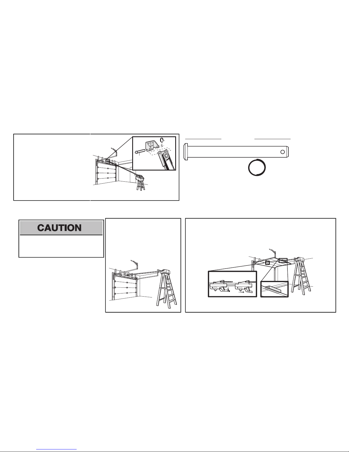
3.1 Align the rail withthe header bracket.
Inserttheclevispin through the holesin
the header bracket and rail. Secure
withthe ring fastener.
NOTE: Use the packing material as a
protective base for the garage door opener.
Ring
Fastener
Clevis Pin
5/16" X 2-3/4"
HARDWARE
Clevis Pin
5/16" x 2-3/4"
Ring Fastener
4 Position the garage door opener
To prevent damage to garage door, restgarage
door opener rail on 2x4 placed on top section of
door.
4.1 Removethe packing material and liftthe
garage door opener onto a ladder.
NOTE: A 2x4 is ideal for setting the distance
between the rail and the door. Ifthe ladder is
not tall enough you will need help at this point.
4.2 Fully open the door and place a 2x4 (laid flat)under therail.
NOTE: Ifthe door hitsthe trolley when itis raised, pull the trolley release arm down to
disconnectthe inner and outer trolley. Slide the outer trolley toward the garage door opener.
The trolley can remain disconnected until instructed.
Connected Disconnected
3 Attach the rail to the header bracket
Page 10

10
5 Hang the garage door opener
To avoid possible SERIOUS INJURY from a falling
garage door opener, fasten it SECURELY to
structural supportsof thegarage. Concrete anchors
MUSTbe used ifinstalling ANY bracketsinto
masonry.
HARDWARE
Hex Bolt 5/16"- 18x7/8"
Nut 5/16"-18
Lock Washer
5/16"
Installation
Hanging your garage door opener will vary depending on your
garage. Two representative installations are shown.Yours may
be different.Hanging brackets should be angled (Figure 1) to
provide rigid support. On finished ceilings (Figure 2), attach a
sturdymetalbrackettostructural supportsbeforeinstalling the
opener. This bracketand fastening hardware are notprovided.
Instructionsbelow are for attaching the garage door opener
directlyto structural supports.
5.1 Measure the distance from eachside of the motorunit to
the structural support.
5.2 Cutboth pieces ofthehanging bracketto required lengths.
5.3 Drill 3/16" pilot holes in the structural supports.
5.4 Attachone end of each brackettoa support with 5/16"-
18x1-7/8" lag screws(notprovided).
5.5 Fastenthe opener to the hanging bracketswith5/16"-
18x7/8" hex bolts,lockwashersand nuts.
5.6 Checkto make sure the rail is centered over the door (or in
line with the header bracketifthe bracket is not centered
above the door).
5.7 Removethe 2x4. Operatethe door manually. Ifthe door
hitsthe rail, raisethe header bracket.
NOTE: DO NOT connect power to opener at this time.
FIGURE 1
FIGURE 2
(Not Provided)
Lag Screws
5/16"- 18x1-7/8"
Measure
Distance
Hex Bolt 5/16"- 18x7/8", Lock Washer 5/16", Nut 5/16"-18
FIGURE 3
Not Provided
Finished Ceiling
Unfinished Ceiling
Page 11

11
To prevent possible OVERHEATING of the end panel or light socket:
• UseONLY A19 incandescent (100Wmaximum)or compactfluorescent(26Wmaximum) light
bulbs.
• DO NOT use incandescentbulbs larger than 100W.
• DO NOT use compact fluorescentlight bulbslarger than 26W (100Wequivalent).
• DO NOT use halogen bulbs.
• DO NOT use shortneckor specialtylight bulbs.
6.1 Pull on the top center of the lightlens and rotate the
light lens down.
6.2 Insertan A19 incandescent (100W maximum) or
compactfluorescent (26W, 100Wequivalent)light
bulb into the light socket.
NOTE: Do not use halogen, short neck,or specialtylight
bulbs as thesemayoverheat the end panel or light socket.
Do not use LED bulbs as they may reduce the range or
performance of your remote control(s).
6.3 Rotatethe lens up to close.
or or
7 Attach the emergency release rope and handle
To prevent possible SERIOUS INJURYor DEATH from a falling garage door:
• Ifpossible,use emergency releasehandle todisengage trolley ONLY when garage door is
CLOSED. Weak or broken springs or unbalanced door could result in an open door falling
rapidly and/or unexpectedly.
• NEVER use emergencyrelease handle unless garage doorwayisclear of personsand
obstructions.
• NEVER use handle to pull door open or closed. If rope knotbecomesuntied, you could fall.
7.1 Insertone end of the emergencyrelease rope
through the handle. Make sure that “NOTICE” is
right side up. Tie a knotat least 1 inch(2.5 cm) from
the end of the emergencyrelease rope.
7.2 Insertthe other end of the emergencyrelease rope
through the hole in the trolley release arm. Mount
the emergency releasewithin reach, but atleast6
feet(1.83 m) above the floor, avoiding contactwith
vehiclesto prevent accidental release and secure
witha knot.
NOTE: Ifit is necessaryto cut the emergency release rope,
seal the cut end with a match or lighter to prevent
unraveling. Ensure the emergencyrelease rope and
handle are above the top ofall vehicles to avoid
entanglement.
Trolley
Re
lease Arm
6 Install the light bulbs
Page 12

12
Fiberglass,aluminum or lightweight steel garage doors WILLREQUIREreinforcementBEFORE
installation of door bracket.Contact your door manufacturer for reinforcement kit.
Figure 1 showsone pieceof angle iron asthe horizontal brace.
For the vertical brace,2 pieces of angle iron are used to create a
U-shaped support. The bestsolution is to check with your garage
door manufacturer for an opener installation door reinforcement
kit.
NOTE: Many door reinforcement kitsprovide for directattachment
of the clevis pin and door arm. In this case you will not need the
door bracket; proceed to the next step.
Self-Threading Screw
1/4"-14x5/8"
HARDWARE
SECTIONALDOORS
8.1 Center the door bracket on the previously marked vertical centerline used for the header bracket
installation.NotecorrectUP placement,as stamped inside the bracket.
8.2 Position the top edge ofthe bracket 2"-4" (5-10 cm) belowthe top edge of the door,OR directly below
any structuralsupport across the top ofthe door.
8.3 Mark,drill holesand install asfollows, depending on your door’sconstruction:
Metal orlight weight doors usinga vertical angle iron brace between the doorpanel support
andthe doorbracket:
• Drill 3/16" fastening holes. Secure the door bracketusing the two self threading screws.
(Figure 2)
• Alternately, use two 5/16" bolts,lockwashers and nuts (not provided). (Figure 3)
Metal,insulated orlight weightfactory reinforced doors:
• Drill 3/16" fastening holes. Secure the door bracketusing the self-threading screws.(Figure 4)
WoodDoors:
• Use top and bottom or side to side door bracket holes. Drill 5/16” holes through the door and
secure bracket with 5/16"-18x2" carriage bolts,lockwashersand nuts(notprovided). (Figure 5)
NOTE: The 1/4"-14x5/8" self-threading screws are not intended for use on wood doors.
8 Install the door bracket
A horizontal and vertical reinforcement
is needed for lightweight garage doors
(fi berglass, aluminum, steel, doors
with glass panel, etc.) (not provided).
A horizontal reinforcement brace
should be long enough to be secured
to two or three vertical supports.
A vertical reinforcement brace should
cover the height of the top panel.
FIGURE 1
FIGURE 2
FIGURE 4
FIGURE 5
FIGURE 3
Vertical Reinforcement
Vertical Centerline
of Garage Door
UP
Door Bracket
Self-Threading Screw
1/4" - 14x 5/8"
Self-Threading
Screw
1/4" - 14x 5/8"
Vertical Reinforcement
Bolt 5/16"-18x2"
(Not provided)
Lock Washer 5/16"
Nut 5/16"-18
Door Bracket
UP
Vertical Centerline
of Garage Door
UP
Vertical
Centerline of
Garage Door
Bolt 5/16"-18x2"
(Not provided)
UP
Inside Edge of Door or
Reinforcement Board
Vertical Centerline
of Garage Door
Installation
Page 13

13
IMPORTANT: The groove on the straight door arm MUST face away from the curved door arm.
Straight
Door Arm
Curved
Door
Arm
(Groove
facing out)
CORRECT
INCORRECT
Straight
Door
Arm
Curved
Door
Arm
9.1 Close the door.Disconnect the trolley by
pulling the emergency releasehandle.
Slide the outer trolley back(awayfrom
the door) about 2"(5 cm).
9.2 Attachthe straight door arm to the outer
trolley using the clevispin.Attachwith
the ring fastener.
Ring
Fastener
Clevis Pin
5/16" x 1"
9.3 Attachthe curved door arm to thedoor
bracketusing the clevis pin. Attach with
the ring fastener.
Ring
Fastener
Clevis Pin
5/16" x 1-1/4"
HARDWARE
Hex Bolt 5/16"-18x7/8"
Nut
5/16"-18
Lock
Washer
5/16"
Clevis Pin
5/16"x1"
Clevis Pin 5/16"x1-1/4"
Ring Fastener
9.4 Align the straight door arm with the
curved door arm.Select two aligned
holes (as farapart as possible) and
attach using the bolts, nuts and lock
washers.
Nut 5/16"
- 18
Lock
Washer
5/16"
Hex Bolt
5/16" - 18 x 7/8"
NOTE: Ifthe holes do not line up, reverse the
straight door arm.Selecttwo aligned holes (as
far apart as possible) and attachusing the
bolts,nutsand lock washers.
If the straight door arm is hanging
down too far, you may cut
6 inches
(15 cm) from the solid end.
Nut 5/16" - 18
Lock
Washer
5/16"
Hex Bolt
5/16" - 18 x 7/8"
9.5 Pull the emergency releasehandle
toward the garage door opener until the
trolley release arm is horizontal. The
trolley will re-engage automatically when
the garage door opener is activated.
Trolley
re
lease
arm
9 Connect the door arm to the trolley
Page 14

14
1 Install the door control
Install the Door Control
To prevent possible SERIOUS INJURYor DEATH from electrocution:
• Be sure power isNOTconnected BEFORE installing door control.
• Connect ONLY to12 VOLTlow voltage wires.
To prevent possible SERIOUS INJURYor DEATH from a closing garage door:
• Installdoor controlwithin sight of garage door, outof reach ofchildren ata minimum heightof5 feet
(1.5 m), and away from ALL moving parts of door.
• NEVER permitchildren to operate or playwithdoor controlpush buttons or remote control
transmitters.
• Activatedoor ONLYwhen it can be seen clearly,is properly adjusted,and there are no
obstructions to door travel.
• ALWAYS keep garage door in sight until completelyclosed.NEVER permit anyone to crosspath of
closing garage door.
INTRODUCTION
Compatible with MyQ®and Security+ 2.0™
accessories, see page 37. Your garage door
opener is compatible with up to 2 SmartControl
Panels or 4 ofanyother Security+ 2.0™ door
controls.NOTE:Older LiftMaster door controls
and third party products are not compatible.
Install the door controlwithin sight of the door at
a minimum heightof 5 feet(1.5m) where small
children cannotreach,and awayfromthe
moving parts of the door.
NOTE: Your product may look different than
moving parts of the door the illustrations.
Screw
6ABx1"
HARDWARE
Drywall
Anchors
Screw
6-32x
1"
NOTE: For gang box installations it is not necessarytodrill holes or install the drywall anchors. Use the existing holesin the gang box.
1.1 Strip 7/16 inch (11 mm)of insulation from
one end of the wire and separate the wires.
7/16"
(11
mm)
1.2 Connectone wire to each ofthe two screws
on the backof the door control.The wires
can be connected to either screw.
PRE-WIREDINSTALLATIONS:Choose
any two wires to connect,note which wires
are usedso the correct wires are connected
at the garage door opener in a later step.
1.3 Mark the location ofthe bottom mounting
hole and drill a 5/32inch (4 mm)hole.
Wall
1.4 Install the bottomscrew,allowing 1/8 inch
(3 mm) to protrude from the wall.
Screw
6-32 x
1"
DRYWALL
GANG BOX
Screw
6AB x 1"
Drywall Anchor
Page 15

15
k
Install the Door Control
1.5 Position the bottom hole of the door
control over the screwand slide
down into place.
1.6 Lift the pushbar up and markthe top hole. 1.7 Removethe door control from the wall
and drill a 5/32 inch (4 mm) hole for
the top screw.
1.8 Position the bottom hole of the
door controlover the screw and
slide down into place. Attach the
top screw.
DRYWALL
Drywall Anchor
Screw
6-32 x 1"
Screw
6AB x 1"
GANG
BOX
2 Wire the door control to the garage door opener
HARDWARE
Insulated Staple
(N
ot shown)
PRE-WIREDINSTALLATIONS: When wiring
the door control to the garage door opener
make sure you use the same wires thatare
connected to the door control.
2.1
Run the white and red/white wire fromthe door controlto
the garage door opener. Attach the wire to the wall and
ceiling with the staples (notapplicable forgang box or
pre-wired installations).Do not pierce the wire with the
staple as this may cause a short or an open circuit.
Staple
2.2
Strip 7/16 inch (11 mm)of insulation
fromthe end of the wire near the
garage door opener.
7/16"
(11
mm)
2.3
Connectthe wire to the red and
white terminals on thegarage
door opener. To insertor
release wires fromtheterminal,
push in the tab with screwdriver
tip.
RED
WHITE
WHITE
GREY
Page 16

16
Install the Door Control
3 Attach the warning labels
3.1 Attach the entrapment warning label on the wall near the door control with tacksor
staples.
3.2 Attach the manual release/safety reverse test label in a visible location on the inside of
the garage door.
Page 17
17
Introduction
Be sure power is NOTconnectedto the garage
door opener BEFORE installing the safety
reversing sensor.
To prevent SERIOUS INJURY or DEATH from
closing garage door:
• Correctlyconnectand align the safety
reversing sensor. This required safety
device MUSTNOT be disabled.
• Installthe safetyreversing sensor so beam
is NO HIGHER than 6" (15 cm) above
garage floor.
Install the Protector System
®
IMPORTANTINFORMATIONABOUTTHESAFETYREVERSINGSENSORS
Thesafety reversing sensors must be connected andalignedcorrectly before the garage dooropener willmove in the down direction.
The sending sensor (with an amber LED)transmits an invisible light beam tothe receiving sensor (witha green LED). If an obstruction breaksthe light
beam while the door is closing, the door will stop and reverse to the full open position,and thegarage door opener lightswill flash 10 times.
NOTE: For energyefficiency the garage door opener will enter sleep mode when the door is fully closed. The sleep mode shuts the garage door
opener down until activated. The sleep mode is sequenced with the garage door opener light bulb;as the light bulb turns off the sensor LEDs will turn
off and whenever the garage door opener lights turn on the sensor LEDswill light. The garage door opener will not go into the sleep mode until the
garage door opener has completed 5 cycles upon power up.
Wheninstalling the safety reversingsensors check the following:
• Sensorsare installed inside the garage, one on eitherside of the door.
• Sensorsare facing eachother with the lensesaligned and the receiving sensor lensdoes not receive directsunlight.
• Sensorsare no more than 6 inches (15 cm) above thefloor and the lightbeam is unobstructed.
Invisible Light Beam
Protection Area
Safety Reversing Sensor
6" (15 cm) max. above floor
Safety Reversing Sensor
6" (15 cm) max. above floor
Page 18

Install the Protector System
®
1 Install the Safety Reversing Sensors
The safetyreversing sensors can be attached to the door track,thewall,or the floor.Ifthedoor trackwill not support the sensor bracketa wall installation isrecommended.Choose one of the following installations.
HARDWARE
Carriage Bolt
1/4"-20x1/2"
Wing Nut
1/4"-20
OPTION A
DOOR TRACK INSTALLATION
1.1A Slide the curved armsofthe sensor
bracketaround the edge of the door
track. Snap into place so that the
sensor bracket is flush againstthe
track.
1.2A Slide the carriage bolt into thesloton
each sensor.
Carriage Bolt
1/4" - 20 x 1/2"
1.3A Insert the bolt through the hole in the sensor
bracketand attach with the wing nut.The lenses
on bothsensorsshould pointtowardeach other.
Make sure the lens is not obstructed by the
sensor bracket.
Wing Nut
1/4" - 20
OPTION B WALLINSTALLATION
Ifadditional clearanceis needed an extension bracket(notprovided) or wood blockscanbe used.Makesure each bracket has thesame amount of clearanceso they will align correctly.
1.1B Position the sensor bracket against the
wall with the curved armsfacing the
door. Make sure there is enough
clearance for thebeam to be
unobstructed.Markholes.
(not provided)
1.2B Drill 3/16 inch pilotholes for eachsensor
bracketand attach the sensor brackets
to the wall using lag screws(not
provided).
In
side
G
a
rage
Wal
l
(not provided)
1.3B Slide the carriage bolt into the sloton
each sensor.
Lens
Carriage Bolt
1/4" - 20 x 1/2"
1.4B
Insertthebolt through the hole in the sensor
bracketand attach with the wing nut.The lenses
on bothsensorsshould pointtowardeach
other. Make sure the lens is notobstructed by
the sensor bracket.
Wing Nut
1/4" - 20
18
Page 19

Install the Protector System
®
1 Install the Safety Reversing Sensors
OPTION C
FLOOR INSTALLATION
Usean extension bracket (not provided) or wood block to raisethe sensor bracket if needed.
1.1C Carefully measure theposition of both
sensor bracketsso they will be the same
distancefromthe wall and unobstructed.
1.2C
Attachthe sensor bracketsto the floor
using concrete anchors (not
provided).
Insi
d
e
Garage
Wa
l
l
(not provided)
1.3C
Slide the carriage bolt into the sloton
each sensor.
Carriage Bolt
1/4" - 20 x 1/2"
1.4C
Insertthebolt through the hole in the sensor
bracketand attach with the wing nut.The lens
on bothsensorsshould pointtowardeach
other. Make sure the lens is notobstructed by
the sensor bracket.
Wing Nut
1/4" - 20
2 Wire the Safety Reversing
Sensors
OPTION A
INSTALLATION WITHOUT PRE-WIRING
PRE-WIREDINSTALLATIONS: If your garage
already haswiresinstalled for the safety reversing
sensors,see page 20.
HARDWARE
Insulated Staple
(N
ot shown)
2.1A Run thewire from both sensorstothe
garage door opener. Attach the wire to
the wall and ceiling withthe staples.
Staple
2.2A Strip 7/16 inch (11 mm) of insulation
fromeach set of wires. Separate the
wires.Twistthe white wires together.
Twist the white/blackwires together.
7/16"
(11 mm)
2.3A Insert the white wires intothe white terminal on
the garage door opener. Insert the white/black
wires into the grey terminal on the garage door
opener. To insertor remove the wires from the
terminal,push in the tab with a screwdrivertip.
RED
WHITE
WHITE
GREY
19
Page 20

Install the Protector System
®
OPTION B PRE-WIRED INSTALLATION
2.1B Cut the end of the safety
reversing sensor wire, making
sure there isenough wire to
reach the pre-installed wires
fromthe wall.
2.2B Separate the safetyreversing sensor wires and strip 7/16 inch(11 mm) of
insulation from each end. Choose two of thepre-installed wiresand strip 7/16
inch (11 mm) of insulation fromeach end. Make sure that you choose the
same color pre-installed wires for eachsensor.
7/16"
(11 mm)
7/16"
(11 mm)
Safety reversing sensor wires
Pre-installed
wires
2.3B Connectthe pre-installed wires tothe sensor wires with wire nuts
making sure the colors correspond foreach sensor. For example,
the white wire would connect to the yellowwire and the white/black
wire would connecttothe purple wire.
White
White/Black
Yellow
(for example)
Purple
(for example)
Not Provided
Pre-installed
wires
Safety reversing sensor wires
2.4B At the garage door opener, strip 7/16 inch(11 mm) ofinsulation from each end of the wirespreviouslychosen for the
safety reversing sensors. Twistthe like-colored wires together.
7/16"
(11 mm)
Yellow
Purple
2.5B Insert the wires connected to the white safetysensorwiresto the
white terminal on the garage door opener. Insert the wiresthatare
connected to the white/black safetysensor wiresto the grey
terminal on the garage door opener.
RED
WHITE
WHITE
GREY
Purple
(for example)
Yellow
(for example)
To insert or remove the wires
from
the terminal, push in the
tab with a screwdriver tip.
20
Page 21

21
Power
1 Connect Power
To prevent possible SERIOUS INJURY or DEATH
from electrocution or fire:
• Be sure power is NOT connectedtotheopener,
anddisconnectpower to circuit BEFORE
removing cover toestablish permanent wiring
connection.
• Garage door installation andwiring MUST be in
compliancewith ALL local electrical and building
codes.
• NEVER use an extension cord, 2-wire adapter, or
changeplugin any way to make it fit outlet.Be
sure the opener is grounded.
To avoid installation difficulties, do not activate thegarage door opener at this time.
To reduce the risk of electric shock, your garage door opener has a grounding type plug witha third grounding pin. This
plug will only fit into a grounding type outlet. If the plug doesn’t fit intoyour outlet,contacta qualified electricianto install
the proper outlet.
THEREARETWO OPTIONS FOR CONNECTINGPOWER:
OPTION A
TYPICAL WIRING
Ground Tab
Ground Tab
Green Ground
Screw
Green
Ground
Screw
Ground Wire
Ground
Wire
Black
Wire
White Wire
White Wire
PERMANENT WIRING (Filter Board)
PERMANENT WIRING (Terminal Block)
Wire Nuts
TYPICAL WIRING
Black
Wire
Black
Wire
1.1A Plugin the garage door opener into a groundedoutlet.
1.2A DO NOT rungarage door opener at this time.
OPTION B
PERMANENT WIRING
If permanent wiring is required by your local code, refer to the following procedure.
To makea permanent connection through the7/8inch hole in the top of the motor unit (according to local code):
Wiringthrougha filterboard(8550 modelsmanufacturedbefore April12, 2013):
1.1B Besure power is NOT connected to the opener, and disconnect power to circuit.
1.2B Remove the garage door opener cover andset aside.
1.3B Remove the attachedgreengroundterminal.
1.4B Cut black and whitewires. Strip away 1/2 inch (1 cm) of insulation, 3 inches (7.5 cm) before spade terminals.
1.5B Remove the power cord fromopener.
1.6B Install a conduit or flex cable adapter tothe7/8inch hole.
1.7B Run wires throughconduit, cuttoproper length andstrip insulation.
1.8B Attach with wire nuts provided. Attach the groundwireto the green groundscrew. The opener must be
grounded.
1.9B Properly secure wire under plastic ties so thatwire does notcomein contact withmovingparts.
1.10B Reinstall the cover. DO NOT run garage door opener at this time.
Wiringthrougha terminalblock (8550 models manufacturedafter April 12, 2013 and all 8557 models):
1.1B Remove the motor unit cover screws and set the cover aside.
1.2B Remove the attached3-prong cord.
1.3B Connect the black (line) wire to the screw on the brass terminal; the white (neutral) wire to the screw on the silver
terminal; and the groundwire to the green groundscrew. The opener must be grounded.
1.4B Reinstall the cover.
Page 22

22
2 Ensure the Safety Reversing Sensors are aligned
Thedoor willnotcloseif the sensors
have not been installedandaligned
correctly.
When the light beam isobstructed or
misaligned while the door is closing, the
door will reverse and the garage door
opener lights will flash ten times.Ifthe door
is already open, it will notclose.The
sensorscan be aligned by loosening the
wing nuts, aligning the sensors,and
tightening the wing nuts.
2.1 Checkto make sure the LEDsin bothsensorsare glowing steadily.TheLEDs in both sensorswill glow steadily if they
are aligned and wired correctly.
Green LED
ROSNES GNIVIECERROSNES GNIDNES
Amber LED
If the receiving sensor is in
direct sunlight, switch
it with
sending sensor so it is on the
opposite side of the door.
(invisible light beam)
IFTHEAMBER LED ON THESENDING SENSORIS NOT GLOWING: IF THE GREEN LED ONTHERECEIVING SENSORIS NOT GLOWING:
Make sure there is
power to the garage
door opener.
Make sure the
sensor wire is
not
shorted/broken.
RED
WHITE
WHITE
GREY
Make sure the sensor has been wired
correctly: white wires to white terminal
and white/black wires to grey terminal.
Make sure the sensors are aligned.Make sure the sensor wire is
not shorted/broken.
3 Ensure the Door Control is wired correctly
Ifthedoor controlhas been installed and wired correctly a message will display on the screen.
Power
Page 23

23
Withouta properly installed safetyreversal
system,persons(particularly small children)
could be SERIOUSLY INJURED or KILLED by a
closing garage door.
• Incorrectadjustmentofgarage door travel
limitswillinterfere with proper operationof
safety reversal system.
• After ANY adjustmentsare made,the safety
reversal system MUST be tested. Door
MUSTreverse on contact with 1-1/2" (3.8
cm)high object(or 2x4 laid flat) on floor.
To prevent damage to vehicles,be sure fully
open door providesadequate clearance.
INTRODUCTION
Your garage door opener is designed with
electronic controlsto make setup and
adjustmentseasy. The adjustmentsallow you
to programwhere the door will stop in the
open (UP) and close(DOWN) position. The
electronic controlssense the amount offorce
required to open and closethe door. The
force is adjusted automatically when you
program thetravel.
NOTE: Ifanything interferes with the door’s
upward travel it will stop. Ifanything interferes
with the door’sdownward travel, it will reverse.
To watcha short instructional video on
programming your new garage door opener
use your smartphone to read the QR Code
below:
PROGRAMMING BUTTONS
The programmingbuttonsare located on the
leftside panel of the garage door opener and
are usedto programthe travel.
UP (Open)
DOWN (Close)
UP Button
Adjustment
Button
DOWN Button
PROGRAMMING BUTTONS
Adjustments
Page 24

24
1 Program the
Travel
Withouta properly installed safetyreversal system,persons (particularly small children) could be SERIOUSLY INJURED or KILLED by a closing garage door.
• Incorrectadjustmentofgarage door travellimitswill interfere with proper operation of safetyreversalsystem.
• After ANY adjustments are made, the safetyreversal system MUSTbe tested. Door MUST reverse on contactwith 1-1/2"(3.8 cm) high object (or 2x4 laid flat)on
floor.
1.1 Press and hold the
AdjustmentButtonuntil
the UP Button begins to
flashand/or a beep is
heard.
1.2 Press and hold the UP Button until the door is in
the desired UP position.
NOTE: The UPand DOWNButtonscan be
used to move the door up and down asneeded.
1.3 Once the door is in the desired UP position
press and release the AdjustmentButton. The
garage door opener lightswill flash twiceand
the DOWN Button will begin to flash.
1.4 Press and hold the DOWNButton until the door
is in thedesired DOWN position.
NOTE: The UPand DOWNButtonscan be
used to move the door up and down asneeded.
1.5 Once the door is in the
desired DOWN position
press and release the
AdjustmentButton.The
garage door opener
lights will flash twice
and theUP Button will
begin toflash.
1.6 Press and release the UP Button.When the
door travelstothe programmed UP position, the
DOWNButton will begin to flash.
1.7 Press and release the DOWNButton.Thedoor
will travel to the programmed DOWN position.
Programming iscomplete.
Ifthegarage door opener lightsare flashing 5 times
during the stepsfor Programthe Travel,the
programming has timed out. Ifthe garage door opener
lights are flashing 10 times during the steps for
Program theTravel,the safetyreversingsensorsare
misaligned or obstructed(refer to page 22). When the
sensorsare aligned and unobstructed,cycle the door
through a complete up and downcycle using the
remote control or the UP and DOWN buttons.
Programming iscomplete.Ifyou are unable to operate
the door up and down, repeatthe stepsfor
Programming the Travel.
Adjustments
Page 25

25
2 Test the Safety Reversal System
Withouta properly installed safetyreversal system,
persons (particularly small children) could be
SERIOUSLY INJURED or KILLED by a closing
garage door.
• Safetyreversal system MUST be tested every
month.
• After ANY adjustmentsare made,the safety
reversal system MUST be tested. Door MUST
reverse on contactwith 1-1/2"(3.8 cm) high
object (or 2x4 laid flat)on the floor.
2.1 With the door fully open, placea 1-1/2
inch (3.8 cm) board (or a 2x4 laid flat) on
the floor, centered under the garage
door.
2.2 Press the remote controlpush button to
close the door.The door MUSTreverse
when it makes contactwiththe board.
Ifthedoor stops and does notreverse on
the obstruction,increase the down travel
(refer to Adjustment Step 1).
Repeat the test.When the door reverses
upon contact with the 1-1/2inch board,
remove the board and open/close the
door 3 or 4 times to testthe adjustment.
Ifthegarage door opener continuesto fail
the safetyreversaltest, call a trained door
systemstechnician.
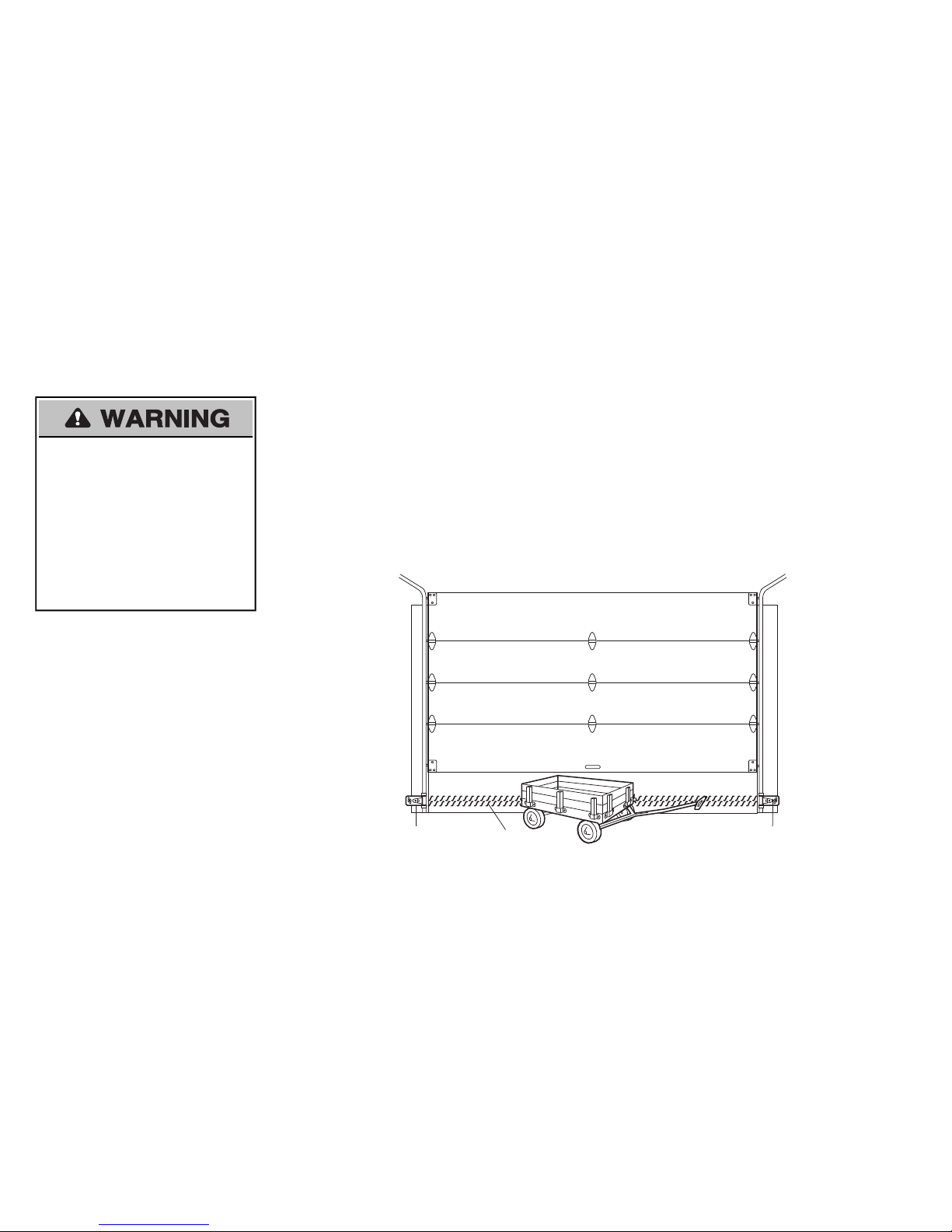
3 Test the Protector System
®
Withouta properly installed safetyreversing
sensor,persons (particularly small children) could
be SERIOUSLY INJUREDor KILLED by a closing
garage door.
3.1 Open the door. Place the garage door
opener carton in thepath of the door.
3.2 Press the remote controlpush button to
close the door.The door will not move
more than an inch (2.5 cm),and the
garage door opener lightswill flash 10
times.
The garage door opener will not close
froma remote control ifthe LED in either
safety reversing sensoris off(alerting you
to the fact thatthe sensor is misaligned or
obstructed).
Ifthegarage door opener closesthe door
when the safety reversing sensor is
obstructed (and the sensors are no more
than 6 inches [15 cm]above the floor),call
for a trained door systemstechnician.
Adjustments
Page 26

26
To reduce the risk of FIREor INJURY to persons:
• DisconnectALL electric and batterypower
BEFORE performing ANY service or
maintenance.
• Use ONLY LiftMasterpart # 485LM for
replacement battery.
• DO NOT disposeofbatteryin fire. Battery may
explode. Check with local codes fordisposal
instructions.
1 Install the battery
1.1 Unplug the garage door opener.
1.2 Open the light lenson the right side panel of the garage door opener. Use a Phillips
head screwdriver to removethe battery cover on the garage door opener.
1.3 Partially insert the batteryintothe battery compartmentwith the terminalsfacing out.
1.4 Connectred (+) and black(-) wires from thegarage door opener tothe
corresponding terminalson the battery.
1.5 Replace the battery cover.
1.6 Plug in the garage door opener.
1.7 Wait for the green Battery Status LED to start flashing beforeproceeding to testthe
battery.
Battery
Status LED
ALWAYS wear protectivegloves and eye
protection when changing the battery or working
around the battery compartment.
*Ifapplicable.
2 Test the battery
2.1
Unplug the garage door
opener. The batterystatus LED
will either glow solid orange
indicating opener is operating
on battery power or will flash
indicating low batterypower.
NOTE: Make sure the garage
door opener is unplugged.
2.2
Open and close the door using the
remote control or door control.
NOTE: The garage door opener may
run slower if the battery is not fully
charged. The batterywill take 24 hours
to fully charge.
2.3 Plug in the garage door opener.Verify
the battery statusLEDflashing green,
indicating the batteryischarging.
Battery Backup*
Page 27

27
Charge the Battery
The battery charges when the garage door opener
is plugged into a 110Vac electrical outletthat has
power and requires24 hourstofullycharge. A fully
charged battery supplies 12Vdc to the garage door
opener for one to two days of normal operation
during an electrical power outage. After the
electricalpower hasbeen restored, the batterywill
recharge within 24 hours.The batterywill last
approximately 1 to 2 years with normal usage.
Instructionsfor replacement are provided withthe
battery.To obtain maximum batterylife and prevent
damage, disconnect the battery when the garage
door opener isunplugged for an extended period
of time,suchas a summer or winter home.
NOTE: When the garage door opener is in battery
backup mode the garage door opener lights,
Timer-to-Close, and Remote Close features are
unavailable.
* Ifapplicable, partnumber 485LM.
Battery Status LED
GREEN LED:
All systemsare normal.
• A solid green LED light indicatesthe batteryis
fullycharged.
• A flashing green LED indicates the battery is
being charged.
ORANGE LED:
The garage door opener has lost power and is in
batterybackup mode.
• A solid orange LED with beep,sounding
approximately every 2 seconds, indicates the
garage door opener isoperating on battery
power.
• A flashing orange LED with beep, sounding
every 30 seconds, indicates the battery is low.
REDLED:
The garage door opener's12V battery needstobe
replaced.
• A solid red LEDwithbeep, sounding every 30
seconds,indicatesthe12V battery will no
longer hold a charge and needsto be
replaced. Replace thebatterybackup to
maintain the battery backup feature.
NOTE: The Battery Status LED is most visible with
the garage door opener light off. Batterydoes not
have to be fully charged to operate the garage
door opener.
Battery Status LED
Battery Backup*
Page 28
28
IMPORTANT SAFETYINSTRUCTIONS
WARNING
To reduce the risk of SEVERE INJURY or DEATH:
1. READ AND FOLLOW ALL WARNINGS ANDINSTRUCTIONS.
2. ALWAYS keep remote controls out ofreach of children.NEVER permit children to operateor
play with garage door control push buttons or remote controls.
3. ONLY activate garage door when it can be seen clearly,itisproperly adjusted,and there are
no obstructionsto door travel.
4. ALWAYS keep garage door in sight and away from people and objectsuntil completely
closed.NO ONE SHOULDCROSS THEPATH OF THE MOVING DOOR.
5. NO ONE SHOULDGO UNDER A STOPPED,PARTIALLY OPENED DOOR.
6. Ifpossible,use emergency releasehandle todisengage trolley ONLY when garage door is
CLOSED. Use caution when using this release withthe door open. Weak or broken springs
or unbalanced door could resultin an open door falling rapidly and/orunexpectedlyand
increasing the riskofSEVERE INJURYor DEATH.
7. NEVER use emergencyrelease handle unless garage doorwayisclear of personsand
obstructions.
8. NEVER use handle to pull garage door open or closed. If rope knotbecomesuntied, you
could fall.
9. AfterANY adjustmentsare made, the safety reversal systemMUSTbe tested.
10. Safety reversal system MUST be tested every month.Garage door MUST reverse on
contactwith 1-1/2"(3.8 cm) high object (or a 2x4 laid flat) on the floor. Failure toadjust the
garage door opener properly increases the riskofSEVERE INJURYor DEATH.
11. ALWAYS KEEP GARAGE DOOR PROPERLY BALANCED (see page 2). An improperly
balanced door may NOT reversewhen required and could result in SEVERE INJURY or
DEATH.
12. ALL repairs tocables,spring assemblies and other hardware,ALL of whichare under
EXTREME tension, MUSTbe made by a trained door systemstechnician.
13. To avoid SERIOUS PERSONAL INJURYor DEATH from electrocution,disconnectALL
electricand battery power BEFORE performing ANY service or maintenance.
14. This operatorsystemis equipped with an unattended operation feature. The door could
move unexpectedly.NO ONE SHOULD CROSS THEPATH OF THE MOVING DOOR.
15. DO NOT enable the Timer-to-Close functionalityif operating either one-piece or swinging
garage doors. To be enabled ONLY when operating a sectional door.
16. SAVE THESE INSTRUCTIONS.
Operation
Page 29

29
Your garage door opener is equipped with features to provide you with greater control over your
garage door operation.
Alert2Close
The Alert2Close feature provides a visual and an audible alert that an unattended door is closing.
Timer-to-Close (TTC)
The TTCfeature automaticallyclosesthedoor after a specified time period that can be adjusted using a
TTCenabled door control (Models881LM or 880LM). Prior to and during the door closing the garage
door opener lightswill flash and the garage door opener will beep.
MyQ
®
MyQ®technology uses a 900MHzsignal to providetwo-waycommunication between the garage door
opener and MyQ®enabled accessories. Your garage door opener iscompatiblewithup to 16 MyQ
®
accessories.
SECURITY+ 2.0™REMOTE CONTROLS AND DOOR CONTROLS
Your garage door opener has already been programmed atthe factorytooperate with your remote
control,whichchanges with each use,randomly accessingover 100 billion new codes. Compatible with
MyQ®and Security+ 2.0™ accessories, see page 37.
NOTE: Older LiftMaster remote controls, door controls, and third party products are not compatible.
SECURITY+2.0
TM
Accessories
MEMORY CAPACITY
Remote Controls Up to 40
Door Controls Up to 2 Smart Control Panels or 4 of any other Security+ 2.0™ door controls
Keyless Entries Up to 4
THE PROTECTOR SYSTEM®(SAFETY REVERSING SENSORS)
When properly connected and aligned, the safety reversing sensorswilldetectan obstruction in the
path of the infrared beam.Ifan obstruction breaksthe infrared beam while the door is closing, the door
will stop and reverse to full open position, and the opener lights will flash 10 times.Ifthe door is fully
open, and the safetyreversing sensors are not installed, or are misaligned,thedoor will not close from
a remote control.However, you can closethe door if you hold the button on the door control or keyless
entry until the door is fully closed.The safetyreversing sensorsdo notaffectthe opening cycle.
ENERGY CONSERVATION
For energyefficiencythe garage door opener will enter sleep mode when the door is fully closed. The
sleep mode shutsthegarage door opener down until activated.The sleep mode is sequenced withthe
garage door opener light bulb; as the light bulb turns off the sensor LEDswillturn off and whenever the
garage door opener lightsturn on the sensor LEDs will light.The garage door opener will not go into
the sleep mode until the garage door opener hascompleted5 cyclesupon power up.
LIGHTS
The garage door opener light bulbswill turn on when the opener isinitially plugged in; power is
restored after interruption, or when the garage door opener is activated.The lights will turn off
automaticallyafter 4-1/2minutes.An incandescent A19 light bulb (100 wattmaximum) or for maximum
energy efficiencya 26W (100W equivalent) compactfluorescent light (CFL) bulb may be used.
Light Feature
The garage door opener is equipped with an added feature;thelights will turn on when someone
enters through the open garage door and the safetyreversing sensor infrared beam isbroken. For
added control over the light bulbs on your garage door opener,see page 30.
USING YOUR GARAGE DOOR OPENER
The garage door opener can be activated through a wall-mounteddoor control,remotecontrol,
wirelesskeylessentryor MyQ®accessory.When the door is closedand the garage door opener is
activated the door will open. If the door sensesan obstruction or isinterrupted while opening the door
will stop.When the door is in any position other than closed and the garage door opener is activated
the door will close. Ifthe garage door opener sensesan obstruction while closing,thedoor willreverse.
Iftheobstruction interruptsthe sensor beam the garage door opener lightswill blink 10 times.However,
you can close thedoor ifyou hold the button on the door control or keylessentryuntilthe door is fully
closed.The safetyreversing sensorsdo notaffect the opening cycle.The safetyreversingsensor must
be connected and aligned correctlybefore the garage door opener will move in the down direction.
BATTERY BACKUP*
The battery backup systemallowsaccess in and out ofyour garage,even when the power isout.When
the garage door opener is operating on battery power, the garage door opener will run slower, the light
will not function, the Battery StatusLED will glow solid orange, and a beep will sound approximately
every 2 seconds.
* Ifapplicable.
Features
Page 30

30
USING THE DOOR CONTROL
SYNCHRONIZETHEDOORCONTROL
To synchronize the door control to the garage door opener, press the pushbar untilthe garage door
opener activates (it may take up to 3 presses). Testthe door control by pressing thepush bar,each
press of the pushbar will activate the garage door opener.
Push Bar
LIGHT
button
Sc
reen
Motion
Se
nsor
Navigation
Buttons
PUSH BAR
Press the push bar to open or close the door.
NAVIGATION BUTTONS
Usethe navigation buttonstomakeselectionsand program features.
LIGHT BUTTON
Press the LIGHT button to turn the garage door opener lightson or off.When the lightsare turned on
theywill stayon untilthe LIGHTbutton is pressed again, or untilthe garage door opener is activated.
Once the garage door opener is activated the lights will turn offafterthe specified period of time (the
factory setting is 4-1/2 minutes).The LIGHTbuttonwill not control the lights when the door isin motion.
The durationof the lighttiming can be adjusted by accessing the menu using the navigation buttons.
SCREEN
The screen will display the time and temperature until the menu button is pressed,and then itwill
display the menu options.Ifthere is a problem with the garage door opener the screen will display the
DiagnosticCode.Referto the Troubleshooting section.
Thefollowingfeaturesare accessible throughthe screen usingthe navigation buttons:
LEARN A DEVICE
Any compatible remote controls, wireless keylessentry,or MyQ®accessories can be programmedto
the garage door opener by accessing the menu and using thenavigation buttons.
LOCK
The LOCK feature is designed to prevent activation of the garage door opener from remote controls
while still allowingactivation from the door controland keyless entry.Thisfeature is useful for added
peace of mind when the home is empty (i.e. vacation).
TIMER-TO-CLOSE (TTC)
DO NOT enable TTCifoperating a one-piece door. TTC is to be used ONLYwithsectional doors.
Factory default issettooff.TTC can be setto automaticallycloseyour garage door fromthe fully open
position after a specified period oftime(1, 5, 10 minute intervals).The garage door opener will Beep
and thelights will Flash beforeclosing the door.The screen on the door control can displaythe statusof
the TTC.TTC WILL NOT work if the garage door opener is operating by battery power or if the safety
reversing sensors are misaligned. This feature is NOTintended to be the primarymethod of closing the
door. A keyless entry shouldbe installedinthe event ofan accidentallockoutwhen usingthis
feature.
NOTE: Before enabling the TTCfor the firsttime, or if you experience a power outage, cycle the garage
door opener open and closed to allow the TTC to set.
AUTOMATIC LIGHT
MotionSensor
Factory default issettoon. This feature automaticallyturns on thegarage door opener lightswhen
motion is sensed. The lightswillcome on forthe set period of time,then shut off.Ifusing the garage door
opener light as a work light disable the motion sensor, otherwise the light will turn offautomatically if you
are beyond the range of the sensor.
Light Feature
The lights will turn on when someone entersthrough the open garage door and the safetyreversing
sensor infrared beam is broken.
MAINTENANCE ALERT (MAS)
Thisfeature assists the homeowner in ensuring the garage door opener system staysin good working
condition. A maintenancealert message will displayon the screen indicating the garage door opener
maybe in need of maintenance. The factorysetting for the MASfeatureis off and can be activated at
timeof installation. Contactyourinstalling dealer for service.
Door Control
Page 31

31
Smart Control Panel Setup
The features on the door control can be programmed through a seriesof menus on the screen and the navigation buttons.Refer to the descriptionsbelow.
SCREEN
The main screen displaysthe time,
temperature,and currentbatterycharge (if
applicable).
Navigation Buttons
FEATURES
Press the navigation button below "MENU" to view
the Features menu.
CLOCKSETUP:Set the time, choose 12 or 24
hour clockand show/hide clock.
TTCSETTINGS (for sectionaldoors ONLY):
Set the Timer-to-Close feature off/on and setthe
timeinterval before door closes. NOTE: DO NOT
enable TTCifoperating a one-piece door. TTC is
to be used ONLY with sectional doors.
LOCK:Enable/disable lock.
PROGRAM:Add remotecontrols,MyQ®devices,
an extra remote buttonto control your garage door
opener lights,or a keyless entry.
SETTINGS
Press the navigation button below the down arrow
till you see TEMPERATURE to view the Settings
menu.
TEMPERATURE: Display the temperature in
Fahrenheit or Celsiusand show/hide the
temperature.
LANGUAGE: Select a language.
LIGHTSETTINGS: Set duration for garage door
opener light to stay on after operation, selectable
range of 1-1/2 to 4-1/2 minutes.Turn the Motion
sensor off/on,and turn theentry light feature off/on.
CONTRAST:Adjustthe contrastofthe screen.
SERVICE
Press and hold the second navigation button, then
press the LIGHT button to view the Service menu.
SOFTWARE REVISION: Displayssoftware version
information.
CYCLECOUNTON/OFF:Turn the Maintenance
Alert (MAS) on/off.
TRANSMITTERS: Displaysthe number of remote
controls,MyQ®devices,door controls and keyless
entries currently programmed tooperate the
garage door opener.
DISPLAYERROR:Displays any errorsthathave
occurred.
To program a remote control or keyless entry to the garage door opener using the door control, see page 32.
Door Control
Page 32

32
Yourremotecontrol has been programmed at the factorytooperatewithyourgarage dooropener.
Older LiftMaster remote controls are NOTcompatible, see page 37 for compatible accessories.Programming can be done through the door control or thelearn buttonthe garage door opener. To program
additional accessories refer to the instructions provided with the accessoryor visit www.liftmaster.com.Ifyour vehicle is equipped with a Homelink®, you may require an external adapter depending on the
make,model,and year of your vehicle.Visitwww.homelink.com for additional information.
TO ADD,REPROGRAM, OR CHANGE A REMOTE CONTROL/KEYLESS ENTRY PINUSING THE DOOR CONTROL
1 Press the navigationbutton
below "MENU" to view the
Featuresmenu.
2 Use the navigation buttons
to scroll to "PROGRAM".
press
to continue.
3 Select "REMOTE"or
"KEYPAD" to program from
the programmenu.
TO REMOTE
press to continue.
4 Remote Control:
Press the button on the remote control thatyou wish to operateyour
garage door.
Keyless Entry:
Enter a 4-digit personal identification number (PIN)of your choice on
the keylessentrykeypad.Then press the ENTERbutton.
OR
The garage door opener lights will flash (or two clickswill be heard) when
the code hasbeen programmed.
Repeat the steps for programming additional remote controls or keyless
entry devices.Ifprogramming is unsuccessful, programthe remote using
the learn button.
PIN
? ? ? ?
1
2
A
BC
3
DEF
4
GHI
5
JKL
6
MNO
7
P
RS
8
TUV
9
WXY
0
Q
Z
*
#
E
NT
E
R
0 QZ
*
#
ENTER
PROGRAMAREMOTE CONTROLUSING THE LEARN BUTTON ONTHEGARAGEDOOROPENER
1 Locate the Learn button on the garage door opener.NOTE:Your garage
door opener maylook different.
Learn
DEL
Yellow
2
Locate the Program Button on the side oftheremote control.
Program Button
Remote Control
Page 33

33
3 Using a safety pin or paper clip, press the
program button until the LEDs on the front of
the remote control turn on.
4 Press and release the Learn buttonon the
garage door opener. The Learn LEDwill light.
Within 30 seconds...
5 Press and release the remote control button you wantto use...
Checktosee if the garage door opener lightbulb blinks. Ifnot,waitfor the remote control LEDto
light solid then slowlypress and release the remotecontrol button again.
Repeat until the light bulb blinks.DONOTpressthe button after the lightbulb blinks.
6 To exit programmingmode, press any remotecontrolbutton except the button that was just
programmed.
7 To test,pressthe programmed buttonon the remote control... The garage door opener will
activate.
To Erase the Memory
ERASE ALL REMOTE CONTROLS AND KEYLESS ENTRIES
1 Press and hold the learn buttonon garage door opener until the learn LEDgoes out
(approximately 6 seconds). All remote control and keylessentrycodesare nowerased.
Reprogram anyaccessory you wish to use.
ERASE ALL DEVICES (Including MyQ®enabled accessories)
1 Press and hold the learn buttonon garage door opener until the learn LEDgoes out
(approximately 6 seconds).
2 Immediatelypressand hold the learn button again until the learn LED goes out.All codes are
now erased.
Reprogram anyaccessory you wish to use.
Remote Control
Page 34

34
To prevent possible SERIOUS INJURYor DEATH from a falling garage door:
• Ifpossible,use emergency releasehandle todisengage trolley ONLY when garage door is
CLOSED. Weak or broken springs or unbalanced door could result in an open door falling rapidly
and/or unexpectedly.
• NEVER use emergencyrelease handle unless garage doorwayisclear of personsand
obstructions.
• NEVER use handle to pull door open or closed. If rope knotbecomesuntied, you could fall.
DISCONNECTTHETROLLEY
1 The door should be fully closed if possible.
2 Pull down on the emergency releasehandle.
RECONNECT THE TROLLEY
The lockout feature prevents the trolley fromreconnecting automatically.
1 Pull the emergency release handle down and back(toward the
opener). The door can then be raised and lowered manually as often
as necessary.
2 To disengage the lockout feature, pull the handle straightdown.
The trolley will reconnecton the nextUP or DOWNoperation, either
manually or by using the door controlor remote control.
NOTICE
NOTICE
Maintenance
EVERY MONTH
• Manually operatedoor. If it is unbalanced or binding, call a trained door systemstechnician.
• Checktobe sure door opens and closesfully.Adjustifnecessary, see page 24.
• Testthesafety reversal system.Adjustif necessary, see page 25.
EVERY YEAR
• Oil door rollers,bearings and hinges. The garage door opener does notrequire additional
lubrication. Do not grease the door tracks.
• Testthebatteryand consider replacing the batterytoensure the garage door opener will operate
during an electrical power outage, see page 26 to testthe batterybackup.
EVERY TWO TOTHREEYEARS
• Usea rag to wipe awaythe existing grease fromthegarage door opener rail. Reapply a small layer
of white lithium greaseto the top and underside of the rail surface where the trolley slides.
NOTICE: To comply with FCC and /or IndustryC anada(IC) rules, adjustment or modifications of thistransceiver are prohibited. THERE
ARE NO USER SERVICEABLE PARTS. Any chang es or modifications not expresslyapp roved by the party responsible for compliance
could voidthe user'sau thoritytooperate the equipment.
Thisdevice complies with Part15o fthe FCC rulesa nd IC RSS-210. Operation issub jectto thefollowingtwo conditions: (1)thisde vice may
not cause harmful interference, and (2) this device must accept an y interference received, including interference that may cause
undesired op eration.
ThisClass Bdigital appa ratus complieswithC anadianICES-003 .
AVIS: Les règlesd elaFCC et/ou d’Indu strieCanada (IC) interdisent toutajustement ou tou te modificationd ecerécepteur. IL N’EXISTE
AUCUNE PIÈCESUSCEPTIBLE D’ÊTREENTRETENUEPARL’UTILISATEUR.Tout changement ou toute modification no n
expressément approuvé par lapartie responsablede la confo rmité peutavoirpourrésultat d'annuler l'autorité de l'utilisateur de faire
fonctionnerl'équ ipement.
Cet appareilest conformeau xdispositions de lapartie15 du règlement de la FCCet de l'normeICRSS-210. Son utilisationestassujettie
aux deuxconditoinssuivantes :(1)ce dispositifne p eut causer des interférencesnuisibles,et(2)ce dispositifdoitacceptertoute
interféren cerecue, ycomprisun einterférencepouvant causer un fonctionnementnon souhaité.
Cet appareilnu meriqued elaclasseBest conforme a lanormeN MB-003 du Canada.
THE REMOTE CONTROL BATTERY
To prevent possible SERIOUS INJURYor DEATH:
• NEVER allowsmall children near batteries.
• If batteryis swallowed,immediatelynotifydoctor.
To reduce riskoffire,explosion or chemicalburn:
• Replace ONLY with 3V2016 coin batteries.
• DO NOT recharge, disassemble,heat above 212°F (100°C) or incinerate.
To replace the batteries,remove the two screwsand open the remote
control housing. Pushthe battery out of the holder for removal. Insert
replacement batteries positive side up (+).
Replace the batteries with only3V2016 coin cell batteries.Disposeof
old batteries properly.
Batteries
Screws (2)
To Open the Door Manually
Page 35

35
Diagnostic Chart
Your garage door opener is programmed with self-diagnosticcapabilities.The UP and DOWN arrows on the garage door opener flashthe diagnostic codes.
DIAGNOSTICCODE SYMPTOM SOLUTION
Up Arrow
Flash(es)
Down Arrow
Flash(es)
1 1 Thegarage door opener will not close and the light
bulbs flash.
Safetysensorsare not installed, connected or wires may be cut.Inspectsensor wires for a disconnected
or cut wire.
1 2 The garage door opener will not close and the light
bulbs flash.
There is a short or reversed wire for the safetysensors. Inspectsafety sensor wire atall staple points
and connection pointsand replace wire or correctas needed.
1 3 The door control will notfunction. The wires for thedoor controlare shorted or the door control isfaulty.Inspectsafety sensor wire at all
staple points and connection points and replace wire or correctas needed.
1 4 The garage door opener will not close and the light
bulbs flash.
Safetysensorsare misaligned or were momentarilyobstructed. Realign both sensors to ensureboth
LEDs are steady and not flickering. Make sure nothing is hanging or mounted on the door that would
interrupt the sensors pathwhile closing.
1 5 Door moves 6-8" stops or reverses. Manually open and closethe door. Checkfor binding or obstructions,such asa broken spring or door
lock,correctasneeded. Check wiring connectionsattravelmodule and at the logic board.Replace
travel module ifnecessary.
No movement,only a single click. Manually open and closethe door. Checkfor binding or obstructions,such asa broken spring or door
lock,correctasneeded. Replace logic board if necessary.
Opener hums for 1-2 secondsno movement. Manuallyopen and close the door. Check for binding or obstructions,such as a broken spring or door
lock,correctasneeded. Replace motorif necessary.
1 6 Door coast after it has come toa complete stop. Program traveltocoastingposition or have door balanced by a trained technician.
2 1-5 No movementor sound. Replace logic board.
3 2 Unable to setthetravel or retain position. Checktravelmodule for proper assembly,replace ifnecessary.
3 3 The battery statusLED*isconstantly flashing green. Battery backup charging circuiterror, replacelogic board.*(ifapplicable)
Troubleshooting
Page 36

36
DIAGNOSTICCODE SYMPTOM SOLUTION
Up Arrow
Flash(es)
Down Arrow
Flash(es)
4 1-4 Door is moving stops and or reverses. Manually open and closethe door. Checkfor binding or obstructions,such asa broken spring or door lock,
correctas needed.Ifthe door is binding or sticking contact a trained door systemstechnician.Ifdoor is not
binding or sticking attempttoreprogram travel (refer to page 24 ).
4 5 Opener runs approximately 6-8", stops and reverses. Communication error to travel module. Check travel module connections,replace module if necessary.
4 6 Thegarage door opener will not close and the light
bulbs flash.
Safetysensorsare misaligned or were momentarilyobstructed. Realign both sensors to ensureboth LEDs
are steady and not flickering. Make sure nothing is hanging or mounted on the door thatwould interrupt
the sensor's path while closing.
Thegaragedoor openercanbeep forseveral reasons:
• (Ifapplicable) Operating on battery power or the 12 Vdc battery needsto be replaced,
see page 27.
• Garage door opener has been activated through a deviceor feature such asTimer-toClose,garage door monitor or LiftMaster Internet Gateway, see page 29.
My remote controlwill not activate the garage door:
• Verify the lockfeature is not activatedon the door control.
• Reprogram the remote control.
• Ifthe remote control willstillnot activatethe door checkthediagnostic codes to ensure
the garage door opener is working properly.
My doorwill not close and the lightbulbs blink on my motorunit:
The safetyreversing sensor must be connected and aligned correctlybefore the garage
door opener will move in thedown direction.
• Verify the safety sensorsare properly installed, aligned and free of anyobstructions.
My garage dooropener light(s) willnotturnoffwhenthe doorisopen:
The garage door opener is equipped with a featurethatturns the light on when the safetyreversing sensors
have been obstructedor when the motion sensor on the door control detectsmovementin the garage. These
featurescan be disabled usingthe door control,see page 31 .
My neighbor’s remote controlopens my garagedoor:
Erase the memoryfromyour garage door opener and reprogram the remotecontrol(s).
TheLEDs onthe doorcontrolblink:
Ifyou have a Smart Control Panel installed and the TTC is set to a custom time, press the ONbutton on the
Premium Motion-DetectingControl Panel to set the time properly.
My vehicle's Homelink®is not programmingtomy garage dooropener:
Depending on the make,model,and year of your vehicle an external adapter may be required. Visit
www.homelink.com for additional information.
Troubleshooting
Page 37

828LM LiftMaster®Internet Gateway:
Internetenabled accessory
which connectstothe computer
and allowsyou to monitor and
control garage door openers
and lighting accessoriesenabled
by MyQ®technology.
829LM Garage and Gate Monitor:
Monitor open/closed statusfor up to
4 MyQ®compatible garage door
openers or gate operatorsand
close them from anywhere in the
home.
895MAX 3-Button Premium
MAXRemote Control:
Compatible with LiftMaster
®
garage door openers
manufactured since1993.
Includesvisorclip.
880LM Smart ControlPanel®:
Displaystemperature, time and system
diagnostics;includesa push bar to open
and closethe door and a lock feature for
extra security. SECURITY+ 2.0
™
compatible.
823LM
Remote Light Switch:
Automaticallycontrol your lights
using your garage door opener,
a SECURITY+2.0™remote
control or a LiftMaster®Internet
Gateway.Simplyreplaces your
current wired wall switch.
990LM SurgeProtector:
The Garage Door Opener Surge
Protectoris designed to protect
LiftMaster®garage door openers
against damage fromlightning and
power surges. Easy to install.
893MAX 3-ButtonMAX Remote
Control:
Compatible with LiftMaster
®
garage door openers
manufactured since1993.
Includesvisorclip.
881LM MotionDetectingControlPanelwith
Timer-to-CloseControl:
Multi-function door control with motion
sensor that automaticallyturnsopener lights
on when it detectsa person entering the
garage. SECURITY+ 2.0™compatible.
825LM Remote Light Control:
Automaticallycontrol your lights
using your garage door opener,
a SECURITY+ 2.0™remote
control or a LiftMaster
®
InternetGateway.Plugs into any
interior outlet.
877MAX MAXWireless Keyless Entry:
For use outside ofthe home to
enable accessto thegarage using
a 4-digitPIN.Workswith ALL
LiftMaster®openers from1993present.
890MAX Mini3-ButtonMAXRemote
Control:
Compatible with LiftMaster
®
garage door openers
manufactured since1993.
886LM MotionDetectingControlPanel:
Multi-function door control with motion
sensor that automaticallyturnsopener lights
on when it detectsa person entering the
garage. SECURITY+ 2.0™compatible.
975LM
Laser Garage ParkingAssist:
Laser enables homeowners to
preciselypark vehicles in the
garage.
892LT/894LT 2 & 4 ButtonLearningRemote
Controls:
Compatible with LiftMaster
®
garage door openers
manufactured since1997. Also
compatible with Encrypted DIP
for gate applications.
485LM 12V Battery for Backup System:
Provides backup power to the garage
door opener (ifapplicable).
Accessories
37
Page 38

LIFTMASTER®FIVEYEAR LIMITED WARRANTY
LIFETIMEMOTORANDBELT LIMITED WARRANTY
ONE YEAR LIMITED WARRANTY FOR THEBATTERYBACKUP SYSTEM
The Chamberlain Group, Inc. (“Seller”) warrants to the first retail purchaser of this product, for the residence in which this product is originally installed, that it is free fromdefects in materials and/or
workmanshipfor a period offive years fromthe date of purchase, except that the motor and belt are warranted to be free from defectsin materials and/or workmanship forthe lifetime of the productwhile
you own your residence, and the Battery Backup Systemis warranted to be free fromdefects in materials and/orworkmanshipfor a period ofone year fromthe date ofpurchase.The proper operationof
thisproduct is dependent on your compliance with the instructions regarding installation, operation, and maintenance and testing. Failure to comply strictly withthose instructions will void this limited
warrantyin its entirety.
If,during the limited warranty period, this product appears to contain a defect covered by this limited warranty, call 1-800-528- 9131, toll free, before dismantling this product.You will be advised of
disassemblyand shipping instructions when you call.Then send the product or component,pre-paid and insured, as directedto our service center forwarrantyrepair. Please include a brief description
of the problem and a dated proof-of-purchase receipt with any product returned for warranty repair. Productsreturned to Seller for warranty repair, which upon receipt by Seller are confirmed to be
defective and covered by this limited warranty, will be repaired or replaced (at Seller’s sole option) at no cost to you and returned pre-paid.Defective parts will be repaired or replacedwith new or
factory-rebuilt partsatSeller’s sole option.[You are responsible forany costsincurred in removing and/or reinstalling the productor anycomponent .]
ALLIMPLIEDWARRANTIES FOR THE PRODUCT,INCLUDINGBUTNOTLIMITEDTOANYIMPLIED WARRANTIES OFMERCHANTABILITYANDFITNESS FOR A PARTICULARPURPOSE,ARE
LIMITEDINDURATION TO THE APPLICABLE LIMITED WARRANTY PERIOD SET FORTH ABOVE FOR THE RELATEDCOMPONENT(S), AND NO IMPLIEDWARRANTIES WILLEXISTOR APPLY
AFTER SUCH PERIOD.Some States do not allowlimitationsonhowlong an impliedwarranty lasts, sothe above limitation may notapply toyou.THIS LIMITED WARRANTYDOES NOT
COVER NON-DEFECTDAMAGE,DAMAGE CAUSED BY IMPROPER INSTALLATION, OPERATIONOR CARE(INCLUDING,BUTNOT LIMITED TO ABUSE, MISUSE,FAILURETO PROVIDE
REASONABLE ANDNECESSARY MAINTENANCE,UNAUTHORIZEDREPAIRS ORANYALTERATIONS TO THIS PRODUCT),LABOR CHARGES FORREINSTALLING A REPAIREDOR
REPLACED UNIT,REPLACEMENTOF CONSUMABLE ITEMS(E.G.,BATTERIES INREMOTE CONTROL TRANSMITTERS AND LIGHTBULBS),OR UNITS INSTALLED FOR NON-RESIDENTIAL
USE. THIS LIMITED WARRANTY DOES NOTCOVER ANY PROBLEMS WITH, OR RELATING TO, THE GARAGE DOOR OR GARAGE DOOR HARDWARE,INCLUDING BUTNOTLIMITEDTOTHE
DOOR SPRINGS,DOOR ROLLERS,DOORALIGNMENTORHINGES. THIS LIMITED WARRANTYALSO DOES NOTCOVER ANY PROBLEMS CAUSEDBY INTERFERENCE.UNDER NO
CIRCUMSTANCES SHALLSELLERBELIABLE FOR CONSEQUENTIAL,INCIDENTALOR SPECIALDAMAGES ARISINGINCONNECTIONWITHUSE, OR INABILITY TO USE,THIS PRODUCT.IN
NO EVENT SHALLSELLER’S LIABILITYFORBREACH OF WARRANTY,BREACH OF CONTRACT,NEGLIGENCE ORSTRICTLIABILITY EXCEED THE COST OFTHE PRODUCTCOVERED
HEREBY.NOPERSON IS AUTHORIZED TO ASSUME FOR US ANYOTHERLIABILITYINCONNECTIONWITH THE SALE OF THIS PRODUCT.
Some states do not allow the exclusion or limitation of consequential,incidental or special damages, so the above limitation or exclusion may not apply to you. This limited warranty gives you specific
legal rights,and you may alsohave other rights,which vary fromstate to state.
Warranty
38
Page 39

39
Repair Parts
Rail Assembly Parts Installation Parts
1
3
4
5
7
6
2
NOTICE
UP
CE
I
LING MOUNT ONLY
1
2
3
4
5
6
11
7
8
9
10
Description Part Number
1 Belt - for 7 foot door 41A5434-11
Belt - for 8 foot door 41A5434-13
Belt - for 10 foot door 41A5434-14
2 Belt Pulley Bracket 41B5424
3 Master Link 4A1008
4 One-Piece Rail
7 feet (2.1 m)
2777BD
One-Piece Rail
8 feet (2.4 m)
2778BD
One-Piece Rail
10 feet (3 m)
2770BD
5 Trolley Assembly 41B3869-3A
6 Tensioner Assembly 41B4103
7 Trolley Threaded Shaft 109B48
Not Shown
Owner’s Manual 114A4665
Description Part Number
1 Curved Door Arm 178B35
2 Door Bracket with Clevis
Pin and Fastener
41A5047-1
3 Emergency Release Rope
and Handle
41A2828
4 Header Bracket with
Clevis Pin and Fastener
41A4353-1
5 Remote Control Visor Clip 29B137
6 Safety Sensor Bracket 41A5266-1
7 Safety Sensor Kit
Receiving and sending
sensors with 2-conductor
wire
41A5034
8 Straight Door Arm 178B34
9 White and Red/White Wire 41B4494-1
10 3V2016 Lithium Battery 10A19
Page 40

40
11
12a
4
10
1
9
5
3
6
2
7
8
4
3
12b
Repair Parts
Description Part Number
1 Sprocket and Sprocket Cover with
Screws
41C589-2
2 End Panel with battery cover and light
socket
41D217
3 Light Lens 41A7562
4 Light Socket 41C279
5 Transformer 41A7635
6 Cover 41A7619-2
7 Motor and Travel Module 41D1739-1
8 Travel Module 41A7114-7
9 End Panel and light socket 41D216
10 Receiver Logic Board 45DCT
11a Line Cord (Models manufactured
before April 12, 2013)
41B135
11b Line Cord (Models manufactured after
April 12, 2013)
41B4245-1
12a Filter Board with Screws (Models
manufactured before April 12, 2013)
41B7611
12b Terminal Block (Models manufactured
after April 12, 2013)
41A3150
Not Shown
Wire Harness with Screws (Models
manufactured before April 12, 2013)
41B7418
Wire Harness with Screws (Models
manufactured after April 12, 2013)
041B7610-1
Garage Door Opener Parts - MODEL 8550
Page 41

1
7
4
2
3
5
6
7
6
8
9
10
11
12
13
14
15
Repair Parts
Garage Door Opener Parts - MODEL 8557
© 2013, The Chamberlain Group, Inc.
114A4665 All Rights Reserved
Contact Information
Before calling, please have the model number of the garage door opener. If you are calling
about a Troubleshooting issue, it is recommended that you have access to your garage
door opener while calling. If you are ordering a repair part please have the following
information: part number, part name, and model number.
Address repair parts order to:
The Chamberlain Group, Inc.
6050 S. Country Club Rd.
Tucson, AZ 85706
For installation and service
information call:
1-800-528-9131
Or visit us online at:
www.liftmaster.com
DESCRIPTION
Part Number
1 Cover with screws 41A4371
2 Gear and sprocket 41A4885-5
3 Drive and Worm Gear 41A2817
4 Line Cord 41B4245-1
5 End panel 041A7756
6 Light Socket 41C279
7 Light Lens 41A7562
8 Capacitor 30B652
9 Gear Case 41A5532
10 Terminal Block 41A3150
11 Motor 041A7767
12 Travel Module 041D7742-5
13 Cover 041A7619-4
14 Logic Board 45ACT
15 Logic Board End Panel 41D216
Not Shown
Dual Wire Harness Kit 041A7814
 Loading...