

Page 1
OPERATING MANUAL
INDUSTRIAL DOOR DRIVES
2 YEAR WARRANTY
Serial nummer:
(see motor gearbox)
Installed on:
Switchgear standart:
DK/DKA-SERIES
Page 2

TABLE OF CONTENTS PAGE 2
IMPORTANT SAFETY ADVICE 3 - 4
GENERAL INFORMATION 4
PREPARATORY TASKS 5
INSTALLATION ADVICE
MOUNTING ARRANGEMENT 6
INSTALLATION ADVICE
ELECTRICAL CONNECTION 7
NEC LIMIT SWITCH WITH 8
ILLUSTRATION
CAM LIMIT SWITCH WITH 9
CONNECTING TERMINAL BOARD
CIRCUIT DIAGRAMS STS1 / 10
NEC/MOTOR
CIRCUIT DIAGRAM STS1 11
CAM LIMIT SWITCH WITH
CONNECTING TERMINAL STRIP
+ TST2 CONTROLS 12
CIRCUIT DIAGRAM
EWS2T/TST1 13
TECHNICAL DATA PAGE 14
DK / DKS DRIVES
DIMENSIONAL DRAWINGS
DK / DKS DRIVES
TECHNICAL DATA 15
DKA DRIVES 16
DIMENSIONAL DRAWINGS
DKA DRIVES 1.1
DIMENSIONAL DRAWINGS 17
DKA DRIVES 1.2
CORNER BRACKETS 18
UNIVERSAL BRACKETS
DIMENSIONAL DRAWINGS
WELDED AXES / 19
SET COLLARS/CLAMPING BEARINGS
CALCULATION OF LIFTING SPEED
MAINTENANCE PLAN 20
WARRENTY 21
SPAREPARTS 22
NOTES 23
2
TABLE OF CONTENTS
Page 3
The door should be counterbalanced.
If this is not done then additional
measures must be taken, such as
unwinding protection, to guarantee
proper operation. In the case of DKA
drives unwinding protection is
standard! Non-movable or stuck
doors must be repaired. Doors, door
springs, cables, pulleys, retainers and
rails are under extreme tension in
such situations and this can lead to
serious injuries.
Do not attempt to loosen, move or
realign the door yourself.
Contact your maintenance service.
Suitable protective clothing should be
worn during maintenance or installation
of the door opener. This includes safety
glasses, back supporting belt, and
protective gloves. When installing or
maintaining a door opener no jewellery,
watches or loose clothing may be worn.
When working from ladders or on
extended platforms the corresponding
safety procedures must be followed.
To avoid serious injuries resulting from
getting tangled or caught in the
mechanisms, all ropes and chains,
which are connected to the door,
must be removed before installing the
door opener.
During installation and connection of the
electrical supply the local building and
electrical regulations must be followed.
Power cables may only be connected to
a properly earthed network.
This system must not be installed in
damp or wet rooms.
Work on the door opener may only be carried
out by one (1) person working on his own.
When working on the door opener all
the local safety regulations must be
observed. Installation of this device
must be done according to EN12453.
The force on the closing door edge
must not exceed 150 N(15kg). If the
closing force is set to more than 150N
then the corresponding additional
safety accessories must be installed
(see "Installation of safety applications"). The force must never be
set to move a stuck door.
Too high a force leads to faults in the
proper operation of the reversing system
or to damage to the door.
To remind all operators of the safety
procedures the corresponding warning
sign should be attached beside the
operating control unit.
To avoid damage to the door all the
blocking devices should be deactivated.
If however the blocking devices must
remain in operation an unlatching switch
can be installed.
The three-switch block, main disconnecting switch and all other
control devices must be installed
within view of the door and out of
reach of children. Children should not
be allowed to operate switches or the
remote controller. Misuse of the door
opener can lead to serious injuries.
The door opener may only be
operated if the operator can see the
whole door area, if it is free from
obstacles and the door opener is
properly adjusted. No one may pass
through the door while it is moving
and children must not be allowed to
play in the vicinity of the door.
Before carrying out repairs or removing the covers on the door
opener, it is essential to ensure that
no one can inadvertently start the
drive by installing a lockout device or
disconnecting the cables.
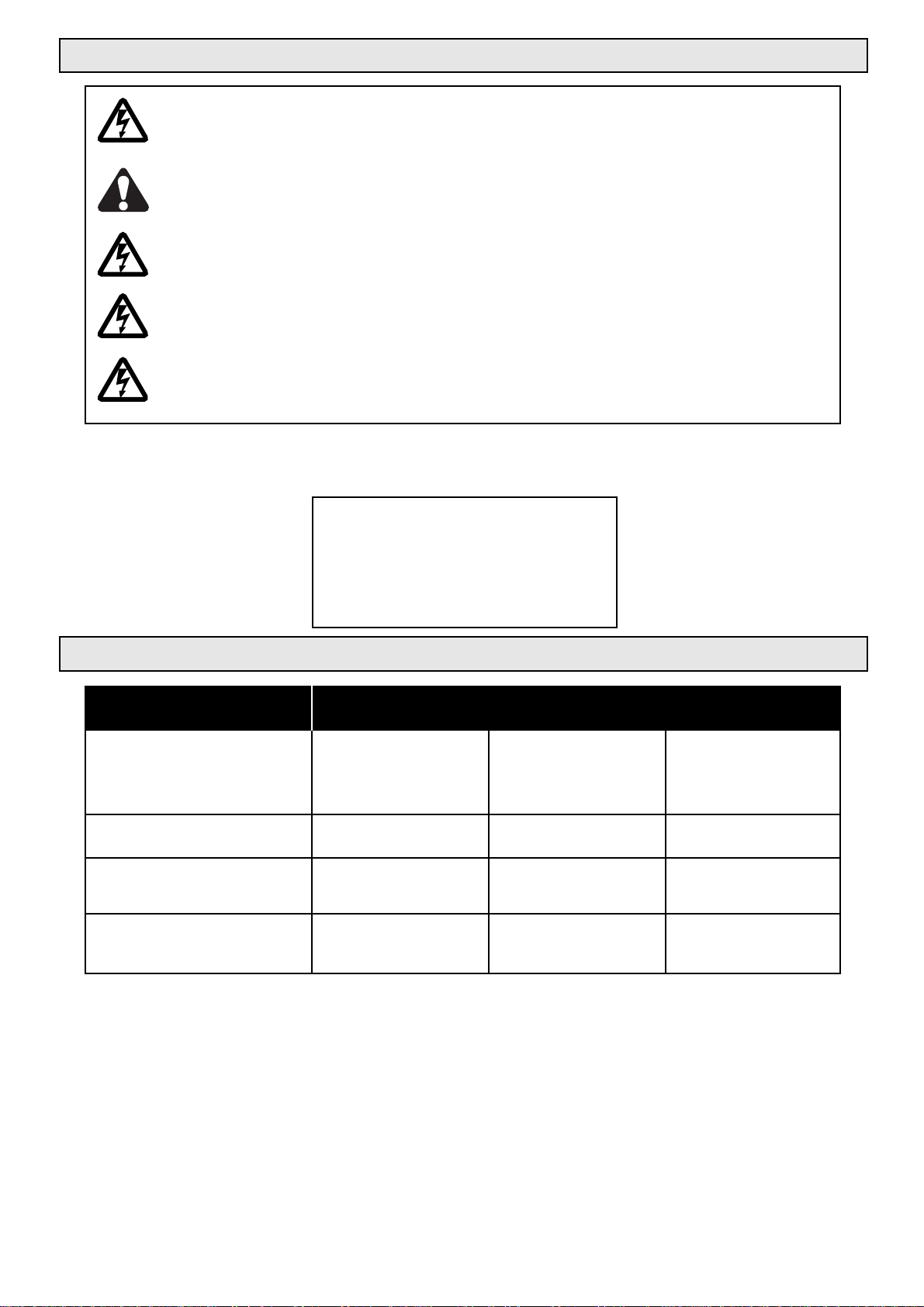
This symbol means "Caution" and stands in front of safety advice intended to avoid
personal injury or material damage. Please read such advice carefully. The door drive is of
course designed and tested for safe operation. It is however only possible to guarantee this
if the following safety instructions are accurately followed during installation and operation.
This symbol is intended to advise that if the respective instruction is not followed serious
personal injury or material damage can occur.
IMPORTANT SAFETY INFORMATION
3
Before installation, operation or maintenance of this door drive,
this operating manual must be read through carefully
and all the safety advice must be followed.
Page 4
In doing so you should also follow:
· The instructions in this manual
· All other project planning documents for the drive
· The start-up instructions and circuit diagrams
· The currently-valid national regulations (safety and accident prevention)
Guarantee, storage
It is essential to follow these instructions and advice since they are the basis for trouble-free operation as well as for any
guarantee claims. Check the delivery immediately after receipt for any transport damage. Report any damage immediately
to the transport company as well as to the supplier. If you do not install the geared motor straight away you should store it in
a dry, dust-free, low-vibration room at temperatures between 0 and +40°C.
Zustand bei Auslieferung
Delivered condition
Every geared motor is manufactured according to the valid technical documentation and subjected to a test run at
Chamberlain. We retain the right to make changes to technical data and design, which are in the interests of progress.
Dispatch takes place in the appropriate packaging.
4
IMPORTANT SAFETY INFORMATION
Live and moving parts of electrical
machines can cause serious or fatal
injuries. The installation, connection
and starting up, as well as maintenance and repair work may only be
carried out by qualified specialist
personnel.
To avoid damage to the door or the
drive, all the locking devices must be
put out of operation. Set locking
device(s) to the "Open" position. If a
lock is to remain in operation an
unlatching switch must be installed.
Please find the technical data for the geared motor
from the type plate or from the attached documents.
We thank you for purchasing our product.
If you still have questions on the installation then please contact:
Chamberlain GmbH, Alfred-Nobel-Str. 4,
66793 Saarwellingen Germany
Tel: (0049)(0)6838-907222
Fax: (0049)(0)6838-907179
e-mail: info@garog-service.de
Internet: www.garog-service.de
GENERAL INFORMATION
Page 5

5
The drive may only be installed:
If the details on the rating plate on the drive correspond with the mains voltage.
If the drive is undamaged
If the ambient temperature is between 0 and 40°C
If the installation height is not more than 1000m above sea level
If the type of protection has been appropriately selected.
Output shafts and mounting surfaces are to be thoroughly cleaned to remove the corrosion protection agent (use standard
commercial solvent). To avoid material damage the solvent must not get onto the sealing edges of the rotary shaft seals.
Abrasive agents must not be used.
To avoid shaft breakages and hence serious or fatal injuries it is essential to note the following during mounting:
The precondition for suitable dimensioning of the shaft with respect to its fatigue strength is stress-free installation and an
immovable bearing device for the gearbox support as well as any additional or essential supporting bearings in each
direction as supplied by the user.
The machine frame and force introduction points are to be designed with respect to construction and strength according to
the bearing forces which arise. The gearbox housing with two bearings and all the other bearing points are located on a
common, stable framework on which the bearing surfaces have been machined in one operation. Thereby the installer
must ensure that any deformation of the frame under load will not have any negative influences on the shaft load. The
screws may only be fully tightened once the gearbox has been accurately aligned. Installation in damp rooms or in the open
air is only permitted following agreement with the manufacturer. If the drives are stored for a lengthy period of time it is also
necessary to discuss this with the manufacturer.
PREPARATORY MEASURES
Before starting the installation work make sure that all the
necessary safety measures have been implemented.
1. Installation
Place machine down on smooth mounting plate or aligned slide rails and tighten fixing
screws uniformly.
Make sure beforehand that:
The drive is not damaged or sticking
The drive has been reprepared after a lengthy storage period
The supply line is switched off and safeguarded against being switched on again
(VDE regs.) (VDE = German assoc. of electronic engineers)
The connections have been made properly
The turning direction of the geared motor is correct
All motor protection devices are active
No other danger sources exist
INSTALLATION ADVICE
Page 6
6
INSTALLATION ADVICE
Commissioning:
During commissioning check whether:
The drive does not get excessively hot
In the event of unusual running noises the drive must be stopped immediately and Customer Services should be
informed. If oil is lost Customer Services should be called, the oil level should be checked by means of the dipstick on the
vent screw and the drive must also be switched off if the level falls below the minimum filling quantity.
T o ensure efficient support in the event of a fault we require the following information:
The data from the type plate on your drive unit
The type and extent of the fault
When and under what accompanying conditions the fault occurred.
Whether the drive was subject to speed variations or other distinctive happenings
Electrical connection
The connections according to the circuit diagram and the maintenance of the electrical drive may only be
carried out by electrical specialist personnel.
The corresponding accident prevention regulations must be followed.
For switching the motor and the brake connections, switching contacts of
utilization category AC-3 acc. to IEC 158 must be used.
The types of line and their cross-sections must be selected according to the
relevant regulations. The nominal flows and the type of connection are given
on the motor type plate. The drive details must agree with the connected
values.
If operated with electronic control devices it is essential to take account of
the corresponding start-up instructions and circuit diagrams.
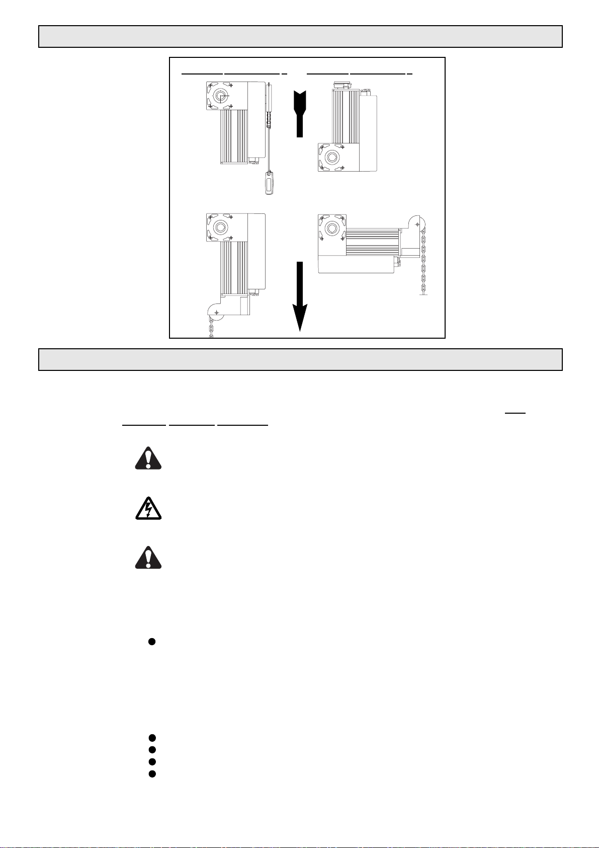
MOUNTING ARRANGEMENT
Closing direction
Mounting arrangement 1
Mounting
arrangement 2
1a 2a
1b
2b
Page 7
7
ELECTRICAL CONNECTION
Before the installation of power cables and control devices it is essential to take note of all the
following specifications and warnings. If they are not heeded serious injuries or damage to the
drive can occur.
The control housing of the door drive may only be opened by trained"Chamberlain" specialist
personnel. If necessary please contact your local Chamberlain dealer.
Before electrical installation or the starting up of the drive please study the circuit diagram
carefully. The valid local regulations must be followed for all the electrical wiring work.
Before carrying out any maintenance work on the door drive it is first necessary to disconnect
the power supply / power transmission at the main switch.
After completion of the maintenance work the danger zone must be cleared and secured again
before restarting.
If you require additional accessories or spare parts
please contact your local Chamberlain dealer.
CHAMBERLAIN - GmbH
Alfred-Nobel-Str. 4
66793 Saarwellingen
ORDERING FAX NO: (0049)(0)6838-907179
TECHNICAL HOTLINE: (0049)(0)6838-907222
l A: Pushbutton for control by holding down continuously
l B: Keyswitch, or suchlike for controlling by means of continuous actuation
l C: Limitation of driving force by force limiting (clutch) and protection devices
(safety edge padding).
l D: Device to detect people or obstacles which are on the ground on one side (inside) of the door
leaf (infrared light barrier)
l E: Device to detect people or obstacles which are on the ground on both sides
(inside and outside) of the door leaf (infrared light barrier).
ADVICE: For more detailed information see EN12453.
MATRIX FOR THE USE OF SAFETY EQUIPMENT
Control by continuous switch
operation
Pulse actuation within visual
range of door
Automatic control
Trained
people(inaccessible
to the public)
Group 1
A
C
C and D
(General public area)
Group 3
No info.
C and E
C and E
Public area
Group 2
B
C and D
C and E
TYPE OF CONTROL DOOR WILL BE USED BY
Page 8
8
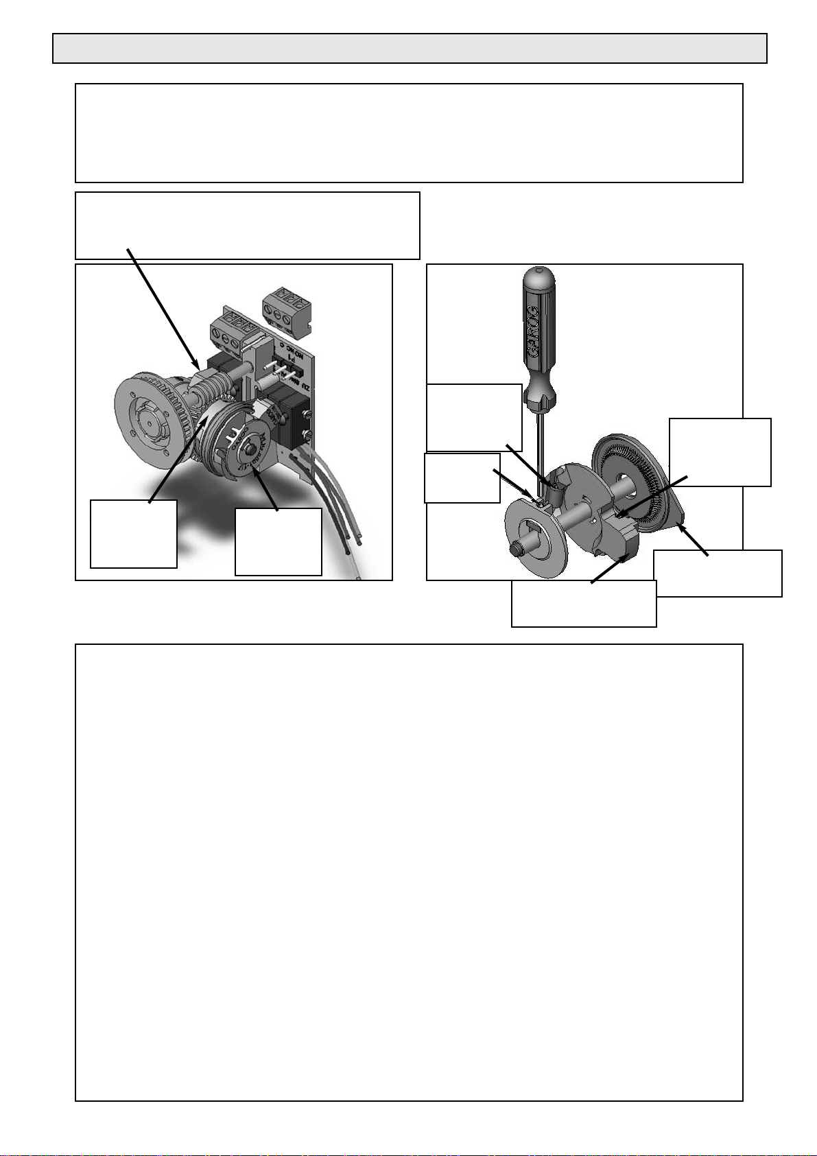
NEC LIMIT SWITCH WITH ILLUSTRATION
Limit switch setting:
The limit switch is delivered in a non-adjusted state. It has two all-purpose cams which each consist of an operating
limit switch and a safety limit switch (black and yellow cams) and potential-free contacts (grey, white and blue
cams). The design of the new cams significantly simplifies the setting of the end positions, since both the end
position as well as the respective safety limit switch can be set in one movement.
The limit switch configuration is explained in the illustration above. Move the door in "dead-man" state to the
end position to be set and place the adjusting screwdriver into the stud screw for coarse setting as shown in
the right-hand picture. Set the all-purpose cams for the corresponding end positions (BLACK for UP and
YELLOW for DOWN) so that the microswitch is almost actuated.
Note: Take note of the approach direction of the cam to the microswitch. Tighten the screw thus
safeguarding the cam from turning.
Now turn the fine setting screw on the operating limit switch until the limit switch is actuated. Check the end
position in travel operation. For re-adjustment purposes the door should always be travelled about 0.5 m
away from the respective end position.
In the normal situation it is not necessary to separately set the safety limit switch since delayed switching of
the safety limit switch is guaranteed due to the special shape of the actuating noses on the all-purpose
cams. This means it is unimportant from which side the microswitch is actuated. However in the normal
case the safety limit switch should be actuated about 10 cm after the normal end position has been
reached. It is possible to alter this switching point at any time by means of the "Safety limit switch - fine
setting" (see picture at top right).
Repeat the procedure for the other end position. If the safety limit switch is actuated an error is displayed
optically in the case of GAROG processor controllers. Don't forget that after finishing the setting work the
coarse setting screws must be tightened up so that the limit switch cannot move during door operation. The
cams in the supplementary contacts, which can be overrun, can only be adjusted with the coarse setting
screw.
Two freely-adjustable changeover contacts
(grey and blue cams) are fitted to plug-in terminals.
A third switch is set as a pre-limit switch (white cam).
"UP"
limit switch,
black
"DOWN"
limit switch,
yellow
Operating
limit switch -
fine setting
Coarse
setting
Safety limit
switch - fine
setting
Switching nose for
safety limit switch
Switching nose for
operating limit switch.
Page 9

CAM LIMIT SWITCH WITH CONNECTING TERMINAL STRIP
9
Redundant safety devices are self-monitoring, i.e. they can detect an error within the
circuit and in the device connections. This type of circuit requires the use of selfmonitoring sensing equipment.
Safety contact for
emergency
chain / crank
Supplementary
limit switch,
grey
Operating
limit switch,
DOWN,
yellow
Operating limit
switch, UP,
black
Safety limit
switch
Controller fuse, 1.6A
Supplementary
limit
switch,
white
Supplementary
limit switch,
blue
Page 10

CIRCUIT DIAGRAM STS1 / NEC / MOTOR
10
Limit switch UP
Limit switch DOWN
Safety limit switch
RELAY
STS1
NEC
INCORRECT
VOLTAGE
DESTROYS
THE TRANS-
FORMER
INCORRECT
VOLTAGE
DESTROYS
THE TRANS-
FORMER
Caution: Earth should be connected to motor housing
Caution: Earth should be connected to motor housing
CONTACTOR
TRANSFORMER
COM
ES UP
VE
SHK
ES DOWN
COM
400V
VOLTAGE
SELECTION SWITCH
VOLTAGE
SELECTION SWITCH
230V
400V
230V
Black
Light blue
Brown
Yellow
Green
Red
24V
LED
STOP
STOP
UP
UP
VE
SKS
DOWN
DOWN
Crank
switch
Thermostat
Limit switch UP
Limit switch DOWN
Safety limit switch
RELAY
CONTACTOR
TRANSFORMER
400V, 3 phase feed
230V, 3 phase feed
COM
ES UP
VE
SHK
ES DOWN
COM
Black
Light blue
Brown
Yellow
Green
Red
24V
LED
STOP
STOP
UP
UP
VE
SKS
DOWN
DOWN
Crank
switch
Thermostat
Page 11

CIRCUIT DIAGRAM - STS1
11
Jumper J1 bridged over =
Self-latching upward travel
Redundant safety devices are self-monitoring, i.e. they can detect an error within the
circuit and in the device connections.
This type of circuit requires the use of self-monitoring sensing equipment.
INCORRECT
VOLTAGE
DESTROYS
THE TRANSFORMER
VOLTAGE
SELECTION SWITCH
400V
230V
Feed cable / CEE plug
"Stabantenne" = Rod aerial
Garog DK series door drive
with STS1 controller
Before switching over
read operating manual
Triple button with LED
Ch. A B C
CFU3 - 3 Channel wireless control
Switching strip with NC contact
Door contact or slack rope switch
Connection example 4: Self-latching
STS1 with triple button, door contact and 3-channel remote controller
Caution: Earth should be connected to motor housing
Caution: Switching over to 230V may only be
carried out in the case of 3 x 230V applications.
UP
STOP
UP DOWN
STOP
UP
DOWN
DOWN
Page 12

CAM LIMIT SWITCH WITH CONNECTING TERMINAL STRIP + TST2 CONTROLS
12
AA
AATTTTTTTTEEEE
NN
NNTTTTIIII
OO
OO
NN
NN!!!!!!!!!!!!
CC
CCIIII
RR
RR
CC
CC
UU
UUIIIITTTT
DD
DDIIII
AA
AA
GG
GG
RR
RR
AA
AA
MM
MM
MM
MM
HH
HH
AA
AASSSS
BB
BBEEEEEEEE
NN
NN
CC
CC
HH
HH
AA
AA
NN
NN
GG
GGEEEE
DD
DD!!!!!!!!
Page 13

CIRCUIT DIAGRAM EWS2T/TST1
13
Page 14

TECHNICAL DATA - DK / DKS DRIVES
14
Chamberlain Garog base set drives include the ready wired door drive with a potential-free cam limit switch
(NE) or a 24V contactor controller (STS) with cam limit switch (NEC). Various types of emergency actuators
are available: The short emergency crank handle (NHK), the automatic emergency chain (NKU) as well as
the quick-action clutch (DKS).
MODEL
TYPE
RPMLIMIT SWITCH EMERGENCY ACTUATION
NHK-Emergency crank handle
NHK-Emergency crank handle
NKU-Emergency crank handle
NKU-Emergency crank handle
NKU-Emergency crank handle
NKU-Emergency crank handle
NKU-Emergency crank handle
NKU-Emergency crank handle
DKS - Quick-action clutch
DKS - Quick-action clutch
Article
Description
Torque bracket E719 - zinc-plated flat steel with fixing screws
for sectional doors DK(S) 70-90
Chain hoist extension (HK4) - 4m chain length, 4 mm,
with two connecting elements.
Articulated crank (E1111) with universal joint, useful in restricted installation
conditions (drive mounted on wall)
Mounting set for indirect drive - DK series - for sectional doors, complete
with assembly brackets (E - 1104), 1" plug-in shaft, setting rings, chain
wheel transmission ratio 1:1, 1.5 m chain, 2 pinions - ½ * 3/16"
Technical data
Type:
Motor power
Torque
Speed
Duty factor
Type of motor protection
[rpm]
DF
Operating voltage
Nominal current
Hollow shaft
Weight:
Accessories for sectional door drives
Page 15

DIMENSIONAL DRAWINGS DK / DKS DRIVES
15
4xM10, depth 20,
362
98
293
270
209
both sides
50
50
74
74
100
49
ª
DK...NKU
293
270
27
98
96,5
49
74
209
50
50
100
74
ª
4xM10, depth 20,
both sides
DK...NHK
M
O
T
O
R
H
A
N
D
293
270
98
96,5
231.5
49
74
209
100
50
74
50
ª
4xM10, depth 20,
both sides
DKS
Fig. 1
Page 16

16
CIRCUIT DIAGRAM: SEK
DIMENSIONAL DRAWINGS DKA DRIVES 1.1
Technical Data
Chamberlain Garog base set drives include the ready wired door drive with a potential-free cam limit switch
(NE) or a 24V contactor controller (STS) with cam limit switch (NEC). Various types of emergency actuators
are available: The short emergency crank handle (NHK), the automatic emergency chain (NKU) as well as
the quick-action clutch (DKS).
K
25
kurze Kurbel
(Serie NHK)
122
108
96.2 72.5
Emergency manual
chain gearbox
NKW (from DKA250)
Emergency manual
chain gearbox
NKU (from DKA200)
94
MODEL
TYPE
RPM
LIMIT SWITCH
EMERGENCY ACTUATION
NHK-Emergency crank handle
NHK-Emergency crank handle
NKU-Emergency crank handle
NKU-Emergency crank handle
NHK-Emergency crank handle
NHK-Emergency crank handle
NHW-Emergency crank handle
A2B-Emergency crank handle
A2B-Emergency crank handle
A2B-Emergency crank handle
A2B-Emergency crank handle
A2B-Emergency crank handle
Type:
Motor power
Torque
Speed
Duty factor
Type of motor protection
n2 [rpm]
DK NHK
DF
DK(S)
Operating voltage
Nominal current
Hollow shaft
Weight:
Arresting torque
ABE no.
Fig. 2
Page 17

a
D
b
=
25
=
25
L1L2
B3
A2
L5
108.5
B4 ... B5
s
9.5
B6
B2
20
Bracket type
OKD5-8
Torque angle
DW1 to DW3
B1
I
0
L3
A1 A2 A3
Space requirement
to lift cover
ª
Articulated food - article G-GF
do not use for DKA120
a
D
b
17
DIMENSIONAL DRAWINGS DKA DRIVES 1.2
Section 2
Fig. 3
Fig. 4
Drive type:
Drive dimensions (in mm)
Page 18

18
DIMENSIONAL DRAWINGS - ANGLE BRACKETS / UNIVERSAL BRACKETS
Fig. 5
L3
6
150
70
45,5
B3
B6
B4...........B5
Fig. 6
WK angle brackets
OKD universal brackets with bearings
Angle brackets: WK3L or 3R /
WK4L or 4R / WK5L or 5R
Bracket
type:
Bracket
type:
Material
thickness
Door
weight
Article no.
for DKA 120
Material
thickness
Door
weight
Article no.
OKD
Page 19

19
DIMENSIONAL DRAWINGS - WELDED AXES / SET COLLARS
CALCULATION OF LIFTING SPEED
L
5
L2
Ød
b x h
M100
Fig. 7
Formula for roller door speed calculation:
Vm = Average lifting speed in cm/sec
D = Largest bale diameter in cm
d = Smallest bale diameter in cm
n = Nominal speed of drive in rpm
3,14 = Circle constant
π
Vm=
(D+d x 3,14 x n)
2 x 60
[cm/sec]
Welded axes / set collars
Axis
Dia. d
w x h
Use
Article no.
Welded axes and set collars
Bearing side
Drive side
Drive side
Both sides
Both sides
Set collar 30
Set collar 40
h9 fit
none
none Bearing side
Table for determination of the lifting speed & lifting force for roller doors
* = Theoretical values, direct on the winding shaft, 20% deduction for friction has already been calculated.
With special door dimensions a load arm increase must be separately considered due to the profile thickness
Roller/bale diameter
V with n2 = 14 rpm
V with n2 = 16 rpm
Lifting force with M = 120 Nm
Vm (sm/sec)
Page 20

20
If for whatever reason your drive does not operate as desired or not as is described in the operating
manual, please first check whether you have read and correctly followed all the instructions. If faults are
still occurring please make contact with your local Chamberlain
dealer who will be happy to support
you in rectifying the fault.
Before carrying out any maintenance work on the door drive it is first necessary to disconnect the
power supply / power transmission at the main/ emergency switch. All maintenance work may only be
carried out by trained "Chamberlain"
specialist
personnel. If necessary please contact your local
Chamberlain
dealer.
MAINTENANCE PLAN
Maintenance
All gearboxes are filled with lubricant in the factory. This lubricant is suitable for at least 1000 operating
hours. After this time or at the very latest every 6 years it is advisable to renew the special oil. For this
purpose only SHELL OMALA 460 should be used in the following filling quantities. The oil quantities for
the different types of drive are as follows:
In the case of low running times and favourable temperature conditions the lubricant may still be fit for use even
after 6 years. In this case however we still recommend that about 1/3 of the given amount of lubricant is added.
If losses of lubricant take place it is necessary to top up with the special oil given above at the correct
time.
Before starting up, a check should be made on whether all the internal and external conditions have been met so
as to ensure perfect functioning.
Drive Filling quantity Filling quantityDrive
Page 21

21
GUARANTEE AND STORAGE
Definition of qualified personnel
Within the meaning of the operating manual and the warning information concerning the product itself, these are people
who are familiar with the setting out, installation, commissioning and operation of the product and have suitable
qualifications for their work, such as:
a. Training or instruction in, and authorization to connect up, switch on and off, earth and mark power circuits and
devices according to the engineering safety standards.
b. Training or instruction according to engineering safety standards in the care and use of the appropriate safety
equipment.
c. Training in first aid.
The fitting of drive elements
The fitting of drive elements such as rope pulleys, wheels etc is best done after previous warming of the respective part.
The preheating temperature should be 100°C.
A precoating of a copper paste eases mounting and provides long-term protection from frictional corrosion.
To avoid damage to bearings, housings and shafts the drive elements must never be mounted on the end of the
shaft by hammer blows.
The fitting of drive elements by means of pressure requires a force introduction surface (seating on output shaft).
Fitted transmission elements must be counterbalanced and must not cause any non-permitted radial or axial forces.
The corresponding tolerances must be observed during the fitting work (see dimension drawing).
Page 22

22
The spare parts kits obtainable for your drive are given in the following parts lists. If your drive
already has optional modifications and/or accessories, certain parts can be added or removed from
the list. Possibly individual parts of a kit are not obtainable - please contact a member of staff
responsible for spare parts and maintenance. He will be happy to inform you about the availability of
individual parts in the kits listed below.
You will find general information on ordering on page 24.
SPARE PARTS
Art. no: GA-DK70/30
Art. no: GA-DK90/22
Art. no: GA-DK120/16
Art. no: GA-DK200/14
NEC cam limit switch system for DK70 - DKA120
NEC cam limit switch system for DK200 - DKA300
NEC cam limit switch system for DK300 - DKA500
NE cam limit switch system for DK70 - DKA120
NE cam limit switch system for DKA200 - DKA300
NE cam limit switch system for DKA400 - DKA500
Art. No.: 041G-NHK-GH1 Emergency hand crank for GH1/DK series
Art. No.: 041G-NHK-GH2 Emergency hand crank for GH2/DK series
Art. No.: 041G-NHK-GH3 Emergency hand crank for GH3/DK series
Art. no: GA-DK250/14
Art. no: GA-DK300/14
Art. no: GA-DK400/14
Art. no: GA-DK500/14
MOTOR / GEARBOX
LIMIT SWITCHES
MECHANICAL SPARE PARTS
Page 23

NOTES
23
Page 24

Anl.-Nr. 709413
This is how to order:
When ordering spare parts or accessories we need
the following information from you:
Part number, description, model number
IN EUROPE
ADDRESS FOR ORDERS:
Chamberlain
-GmbH
Alfred-Nobel-Str. 4
66793 Saarwellingen
TEL. NO. FOR ORDERS:
+(49) 6838-907222
FAX NO. FOR ORDERS:
+(49) 6838-907179
TECHNICAL HOTLINE:
+(49) 6838-907222
ONLINE-SERVICE:
www.garog-service.de
IN NORTH AMERICA
ADDRESS FOR ORDERS:
The Chamberlain Group Inc.
Electronic Parts and Service Department
2301 N. Forbes Blvd., Suite 104
Tucson, Arizona 85745 USA
TEL. NO. FOR ORDERS:
1-520-792-0511
FAX NO. FOR ORDERS:
1-520-884-0966
TECHNICAL HOTLINE:
1-800-528-2806
Declaration of Conformity
The industrial door drive . . . . . . . . . . . . . . . . . . . . . . . . . . . . . . . . . . . . . . . . .
corresponds to the applicable sections and standards . . . . . . . . . . . . .
in accordance with the regulations and amendments
of EU Guidelines……………………………………………………………73/23EEC & 89/336/EEC
Manufacturer's Declaration
Provided that the industrial door drive, Series DK type is installed and maintained in accordance with all the
manufacturer's instructions in conjunction with an industrial door, which is also installed and maintained in accordance
with all the manufacturer's instructions, it meets the regulations of EU Guideline 89/239/EEC in its amended form.
Chamberlain-GmbH
66793 Saarwellingen
August 2004
 Loading...