

Page 1
1/2 hp Chain Drive
Garage Door Opener
FOR RESIDENTIAL USE ONLY
.
.
Write down the following information
for future reference:
Serial Number:
Date of Purchase:
®
PD210 • PD212D •
LW2000 • HD200D •
248730
PD610D • PD612D •
HD400D • LW3000
There are two type of garage door openers pictured.
Yours may appear slightly different.
■ Please read this manual and the enclosed safety materials carefully!
■ Fasten the manual near the garage door after installation.
■ The door WILL NOT CLOSE unless the Protector System
properly aligned.
■ Periodic checks of the garage door opener are required to ensure safe
operation.
■ The model number label is located on the front panel of your garage
door opener.
®
is connected and
CONTENTS
Preparation .............................. 1-4
Assembly ................................. 5-9
Installation ............................ 10-19
Install the Door Control .............20-21
Install the Protector System® ...... 22-25
Power .................................. 26-27
Adjustments .......................... 28-30
Operation.................................. 31
Using Your Garage Door Opener ...... 32
Using the Wall-Mounted
Door Control ..............................32
To Open the Door Manual .............. 33
Care of Your Opener ..................... 33
Having a Problem? ...................... 34
Diagnostic Chart ......................... 35
Programming ......................... 36-37
The Remote Control Battery ............ 38
Accessories ............................... 39
Warranty .............................. 40-41
Repair Parts .......................... 42-43
www.chamberlain.com
The Chamberlain Group, Inc.
845 Larch Avenue
Elmhurst, Illinois 60126-1196
Page 2
Torsion
Spring
Extension
Spring
OR
Preparation
Safety Symbol and Signal Word Review
Thisgarage door opener has been designed and tested to offer safe service provided it is installed,
operated, maintained and tested in strictaccordance with the instructions and warnings contained in this
manual.
When you see these SafetySymbolsand Signal Words on the following pages, they will alert you to the
possibilityof serious injury or death if you do not comply withthe warnings that accompanythem.The
hazard may come from something mechanical or from electric shock.Read the warnings carefully.
Mechanical
Electrical
When you see thisSignal Word on the following pages,it will alert you to the possibilityof damage to
your garage door and/or the garage door opener if you do not comply with the cautionary statementsthat
accompanyit.Read them carefully.
Check the Door
To prevent possible SERIOUSINJURYor DEATH:
• ALWAYS call a trained door systems technician if garage door binds, sticks, or is out of balance.
An unbalanced garage door may NOT reverse when required.
• NEVER tryto loosen, move or adjustgarage door, door springs,cables, pulleys,bracketsor their
hardware, ALLof which are under EXTREMEtension.
• Disable ALLlocksand remove ALLropes connected to garage door BEFORE installation and
operating garage door opener to avoid entanglement.
To prevent damage to garage door and opener:
• ALWAYS disable locksBEFORE installing and operating the opener.
• ONLY operate garage door opener at 120 V, 60 Hz to avoid malfunction and damage.
1. Disable locksand remove any ropes connected to the garage door.
2. Liftthe door halfwayup. Release the door. Ifbalanced,it should stayin
place, supported entirely by its springs.
3. Raise and lower the door to check for binding or sticking.Ifyour door
binds, sticks, or is out of balance, call a trained door systems
technician.
4. Checkthe seal on the bottom of the door. Any gap between the floor
and the bottom of the door mustnot exceed 1/4 inch (6 mm).
Otherwise,the safetyreversal systemmaynot work properly.
5. The opener should be installed above the center of the door. Ifthere is
a torsion spring or center bearing plate in the way of the header
bracket,it may be installed within 4 feet (1.2 m) to the left or right of the
door center. See page 13.
1
Page 3

2
1
3/16
7/16
1/2
5/32
5/16
5/8
9/16
1/4
7/16
Preparation
Additional Items You May Need:
Survey your garage area to see if you will need any of the following items:
n
(2) 2X4 PIECES OF WOOD
Maybe used to fasten the header bracketto the structural supports.Also used to position the
garage door opener during installation and for testing the safetyreversing sensors.
n
SUPPORT BRACKETANDFASTENING HARDWARE
Mustbe used if you have a finished ceiling in your garage.
n
EXTENSION BRACKETS (MODEL 41A5281) OR WOOD BLOCKS
Depending upon garage construction, extension bracketsor wood blocksmay be needed to
install the safetyreversing sensor.
n
FASTENING HARDWARE
Alternate floor mounting of the safetyreversing sensor will require hardware not provided.
n
OUTSIDEQUICKRELEASE (MODEL 7702CB)
Required for a garage with NO access door.
n
DOOR REINFORCEMENT
Required if you have a lightweightsteel,aluminum, fiberglass or glass panel door.
n
RAIL EXTENSION KIT
Required if your garage door is more than 7 feet (2.13 m) high.
Tools Needed
2
Page 4
N
A
B
C
H
K
J
I
D
E
F
G
L
M
P
OR
Models
LW2000,
HD200D
and
248730
All
Other
Models
OR
O Q
Models
PD210D (1)
PD212D (2)
LW2000 (1)
HD200D (1)
248730 (1)
Models
PD610D (1)
PD612D (2)
HD400D (2)
LW3000 (2)
Models
HD400D
LW3000
Preparation
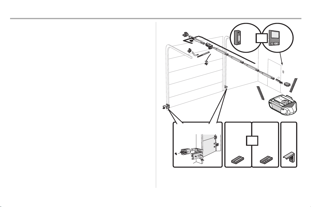
Carton Inventory
Your garage door opener is packaged in one carton which containsthe motor unit and all parts
illustrated below.Accessoriesvary depending on the garage door opener model purchased. Depending
on your model, other accessories may be included with your garage door opener. Instructionsfor these
accessories will be attachedto the accessory and are not included in this manual. If anything is missing,
carefullycheck the packing material. Hardware for assemblyand installation is shown on the nextpage.
Save the carton and packing material until the installation and adjustmentis complete.The images
throughout this manual are for reference only and your product maylook different.
A. Header bracket
B. Pulley
C. Door bracket
D. Curved door arm
E. Straight door arm (Packagedinside front rail section)
F. Trolley
NOTE: Be sure to assemble the trolley before sliding onto rail.
G. Emergency release rope and handle
H. Rail (1 front and 4 center sections)
I. Hanging brackets (2) (Packagedinside the front rail section)
J. Garagedoor opener (motor unit)
K. Chain spreader with screws
L. “U” bracket
M. Chain and cable
N. Door control (Door Control Button or Multi-Function Door Control)
O. Remote control
P. The Protector System
Safetyreversing sensors with 2 conductor white and white/black wire attached:SendingSensor (1),
Receiving Sensor (1), andSafety Sensor Brackets (2)
Q. Keyless Entry (Depending on the model purchased)
NOTSHOWN
White and red/white wire
Owner's manual
®
3
Page 5
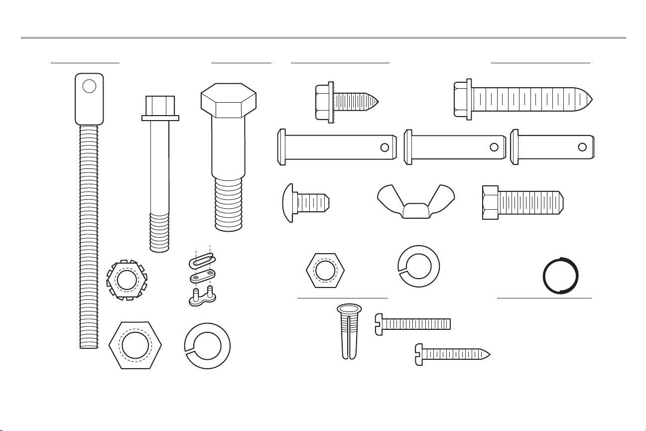
Bolt
1/4"-20x1-3/4"
Lock Nut
1/4"-20
Bolt
Nut 3/8" Lock Washer 3/8"
Master Link
Clevis Pin 5/16"x1-1/2"
Ring Fastener (3)
Hex Bolt 5/16"-18x7/8" (4)
Lock Washer
5/16"-18 (7)
Nut
5/16"-18 (8)
Self-Threading Screw
1/4"-14x5/8" (2)
Clevis Pin 5/16"x1"
Clevis Pin 5/16"x1-1/4"
Carriage Bolt
1/4"-20x1/2" (2)
Wing Nut 1/4"-20 (2)
ASSEMBLY HARDWARE INSTALLATION HARDWARE
Screw 6ABx1" (2)
Drywall Anchors (2)
Screw 6-32x1" (2)
DOOR CONTROL HARDWARE
Insulated
Staples
(
Not Shown)
Lag Screw 5/16"-9x1-5/8" (4)
Threaded
Shaft
Preparation
Hardware Inventory
4
Page 6
Assembly
To garage
door opener
(TO MOTOR UNIT)
Front Rail
Section
(TO DOOR)
“U” Bracket
Outer Trolley
Inner Trolley
Wear Pads
Rail
Tab
Trolley
Window
Cut-Out
SLIDE TO STOPS
ON TOP AND
SIDES OF
“U” BRACKET
Idler
Pulley
Hole
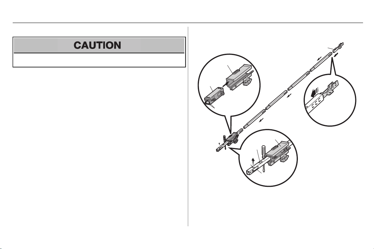
STEP 1 Assemble the rail and trolley
To prevent INJURY from pinching, keep hands and fingers away fromthe joints while assembling the
rail.
To avoid installationdifficulties,do not run the garage door opener untilinstructed to do so.
The frontrail has a cutout “window” at the door end (see illustration). The hole above this window is
larger on the top of the rail than on the bottom.A smaller hole 3-1/2" (8.9 cm) away is close to the rail
edge. Rotatethe back rail so it has a similar hole close to the opposite edge, about 4-3/4" (12 cm) from
the far end.
1. Removethe straight door arm and hanging bracketpackaged inside the front rail and set
aside for Installation Step 5 and 9. NOTE: To prevent INJURY while unpacking the rail
carefully remove the straight door arm stored within the rail section.
2. Align the rail sections on a flat surface as shown and slide the tapered ends into the larger
ones. Tabs along the side will lockinto place.
3. Place the motor unit on packing material to protectthe cover,and rest the backend of the rail
on top. For convenience, put a support under the front end of the rail.
4. As a temporary stop, inserta screwdriver into the hole 10" (25 cm) from the frontend of the rail,
as shown.
5. Checkto be sure there are 4 plasticwear pads inside the inner trolley. If they became loose
during shipping, check all packing material. Snap them back into position as shown.
6. Slide the trolley assemblytoward the screwdriveras shown.
7. Slide the rail onto the “U” bracket,until it reaches all the stops on the top and sides of the “U”
bracket.
5
Page 7
Assembly
(Mounted in the
Bolts
garage
door opener)
HARDWARE
Bolt 1/4"-20x1-3/4"
Lock Nut 1/4"-20
“U” Bracket
Bolts
Hex Screws
8-32x7/16
Cover
Protection
Bolt
Hole
Bolt
1/4"-20x1-3/4"
Lock Nut 1/4"-20
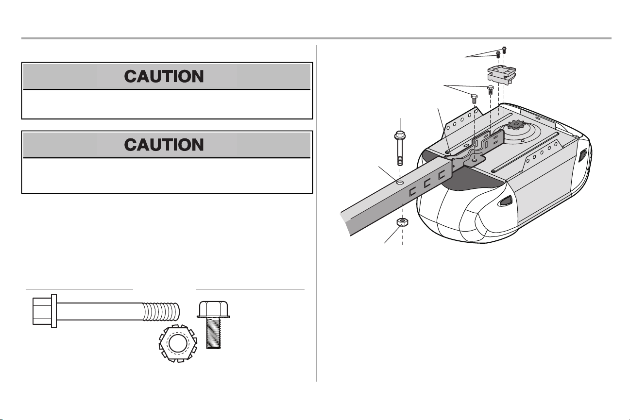
STEP 2 Fasten the rail to the motor unit
To avoid SERIOUS damage to garage door opener, use ONLY those bolts/fasteners mounted in the
top of the opener.
To avoid possible SERIOUSINJURYto fingers:
l
Securely attach chain spreader.
l
NEVERconnect garage door opener to power source until instructed to do so.
1. Inserta 1/4"-20x1-3/4" bolt into the cover protection bolt hole on the backend of the rail as
shown.Tighten securely with a 1/4"-20 lock nut.Do NOT overtighten.
2. Removethe two boltsfrom the top of the motor unit.
3. Usethe carton to support the front end of the rail.
4. Place the “U” bracket,flat side down onto the motor unit and align the bracketholes with the
bolt holes.
5. Fasten the “U” bracketwith the previouslyremoved bolts; DO NOT use any power tools.The
use of power toolsmay permanently damage the garage door opener.
6. Attach spreader to the motor unit withtwo screws.
6
Page 8
Assembly
HARDWARE
Bolt
Nut 3/8"
Lock Washer 3/8"
Screwdriver
Rail
Idler Pulley
Grease Inside Pulley
Bolt
Lock Washer 3/8"
Nut
3/8"
Rail
Tab
CORRECT
INCORRECT
Rail Tab
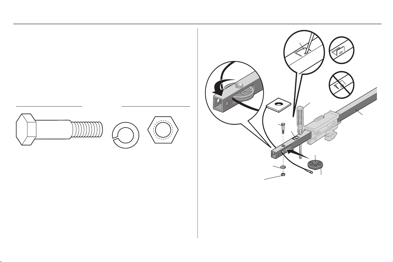
STEP 3 Install the idler pulley
1. Lay the chain/cable beside the rail, as shown. Grasp the end with the cable loop and pass
approximately 12" (30 cm) of cable through the window.Allow it to hang until Assembly Step 4.
2. Removethe tape from the idler pulley.The inside center should be pre-greased. Ifdry,
regrease to ensure proper operation.
3. Place the idler pulley into the window as shown.
4. Insertthe idler boltfrom the top through the rail and pulley. Tighten with a 3/8" lock washer and
nut underneath the rail until the lockwasher is compressed.
5. Rotatethe pulley to be sure it spins freely.
6. Locate the rail tab.The rail tab is between the idler bolt and the trolley in the front rail section.
Usea flat head screwdriver and lift the rail tab until the tab is vertical (90º).
7
Page 9
Assembly
HARDWARE
Master
Link
Threaded Shaft
c.
Threaded
Shaft
Outer
Nut
Front Rail
Section
(TO DOOR)
Inner
Nut
Lock
Washer
Master Link
Master
Link
b.
a.
Sprocket
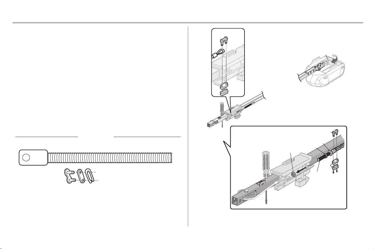
STEP 4 Install the chain
1. Pull the cable around the idler pulley and toward the trolley.
2. Connectthe cable to the retaining slot on the trolley.(a)
3. Withthe trolley against the screwdriver, dispense the remainder of the cable/chain along the
4. Checkto make sure the chain is not twisted, then connect it to the threaded shaftwith the
5. Thread the inner nut and lock washer onto the trolley threaded shaft.
6. Insertthe trolley threaded shaftthrough the hole in the trolley. Be sure the chain is not
7. Loosely thread the outer nut onto the trolley threaded shaft.
8. Removethe screwdriver.
a. Push pins of master link bar through cable link and trolley slot.
b. Push masterlink cap over pins and pastpin notches.
c. Slide clip-on spring over cap and onto pin notches until both pins are securely
locked in place.
rail toward the motor unit into the slot on the chain spreader, around the sprocketonto the
chain spreader and continuing to the trolley assembly.The sprocketteeth mustengage the
chain. (b)
remaining master link.
twisted. (c)
8
Page 10
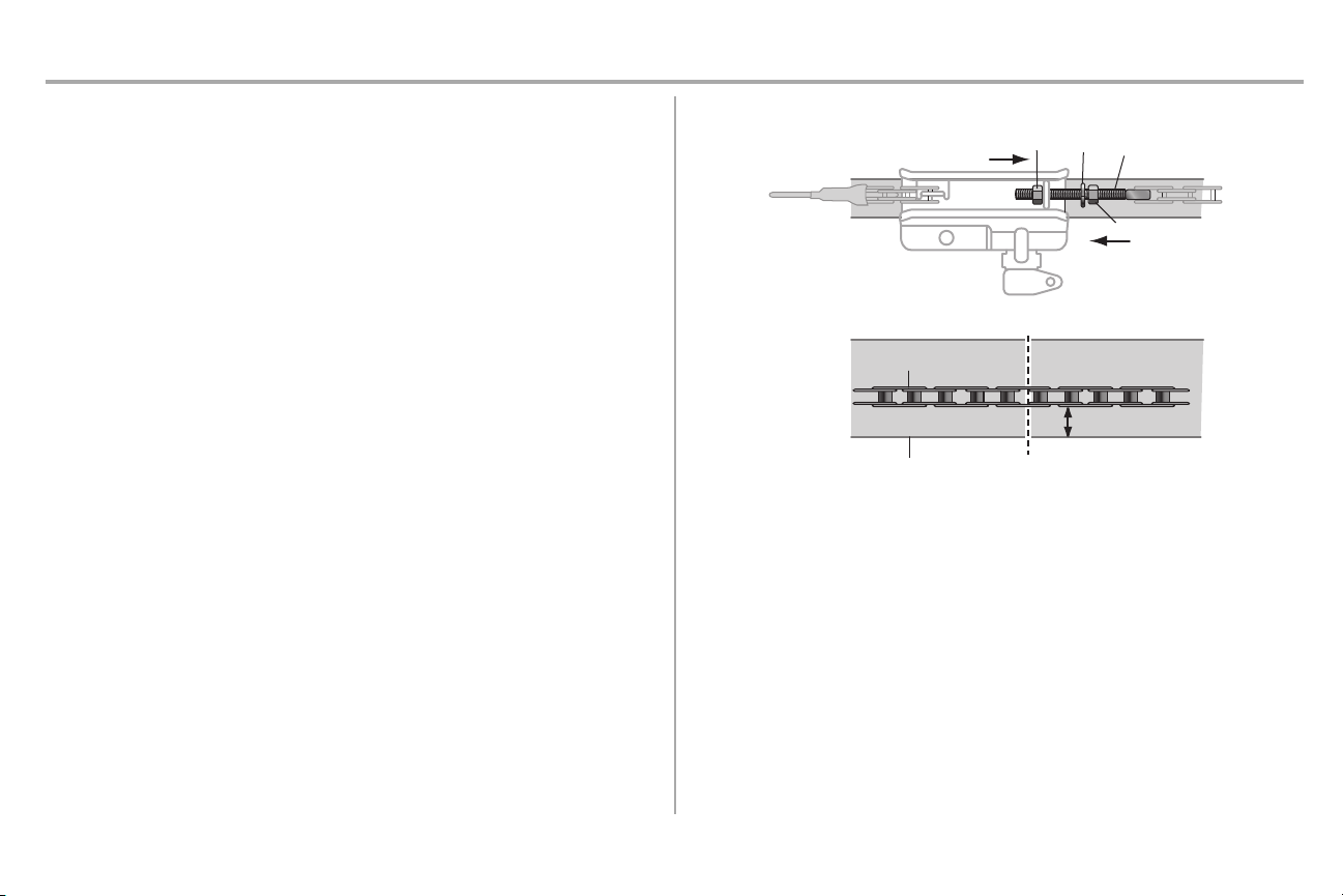
Assembly
Outer
Nut
Lock
Washer
Trolley
Threaded
Shaft
Inner Nut
To Tighten
Inner Nut
To Tighten Outer Nut
Base of Rail
Mid length of Rail
Chain
1/4" (6 mm)
STEP 5 Tighten the chain
1. Spin the inner nut and lock washer down the trolley threaded shaft,awayfrom the trolley.
2. To tighten the chain, turn the outer nut in the direction shown.
3. When the chain is approximately 1/4" (6 mm) above the base of the rail at it's midpoint,retighten the inner nut to secure the adjustment.
Sprocketnoise can result if the chain is too loose.When installation is complete,you may noticesome
chain droop with the door closed. This is normal. Ifthe chain returns to the position shown when the door
is open, do not re-adjustthe chain.
NOTES:
l
During future maintenance, ALWAYS pull the emergencyrelease handle to disconnect the
trolley before adjusting the chain.
l
You may notice loosening of the chain after AdjustmentStep 3 (Test the Safety Reversal
System). Check for proper tension and readjust chain if necessary.Then repeat Adjustment
Step 3.
You have now finished assembling your garage door opener.Please read the following warnings
beforeproceeding to the installation section.
9
Page 11
Installation
IMPORTANT INSTALLATION INSTRUCTIONS
To reduce the risk of SEVERE INJURY or DEATH:
1. READ AND FOLLOW ALL INSTALLATION WARNINGS AND INSTRUCTIONS.
2. Install garage door opener ONLY on properly balanced and lubricated garage door. An
improperly balanced door may NOT reverse when required and could result in SEVERE
INJURY or DEATH.
3. ALL repairs to cables, spring assembliesand other hardware MUST be made by a trained
door systemstechnician BEFORE installing opener.
4. Disable ALL locksand remove ALL ropes connected to garage door BEFORE installing
opener to avoid entanglement.
5. Install garage door opener 7 feet (2.13 m) or more above floor.
6. Mount the emergencyrelease within reach, but at least6 feet (1.83 m) above the floor and
avoiding contactwith vehicles to avoid accidental release.
7. NEVER connectgarage door opener to power source until instructedto do so.
8. NEVERwearwatches,rings or loose clothing while installing or servicingopener. Theycould
be caught in garage door or opener mechanisms.
9. Install wall-mounted garage door control:
• within sight of the garage door.
• out of reach of children at minimum height of 5 feet (1.5 m).
• away from ALL moving partsof the door.
10. Placeentrapment warning label on wall next to garage door control.
11. Placemanual release/safetyreverse testlabel in plain view on inside of garage door.
12. Upon completion of installation,testsafety reversal system.Door MUST reverse on contact
witha 1-1/2" (3.8 cm) high object(or a 2x4 laid flat) on the floor.
13. To avoid SERIOUS PERSONAL INJURYor DEATH from electrocution, disconnectALL
electricpower BEFORE performing any service or maintenance.
10
Page 12
Installation
Header Wall
Vertical Centerline of Garage Door
2x4
Structural
Supports
Level
(Optional)
Unfinished
Ceiling
2x4
OPTIONAL CEILING MOUNT
FOR HEADER BRACKET
Sectional door with curved track
Header Wall
Track
2" (5 cm)
Highest Point
of Travel
Door
One-piece door with horizontal track
Header Wall
Track
2" (5 cm)
Highest
Point
of Travel
Door
One-piece door without track:
jamb hardware
Header
Wall
8" (20 cm)
Highest
Point of
Travel
Door
Jamb
Hardware
One-piece door without track:
pivot hardware
Header Wall
8" (20 cm)
Highest
Point of
Travel
Door
Pivot
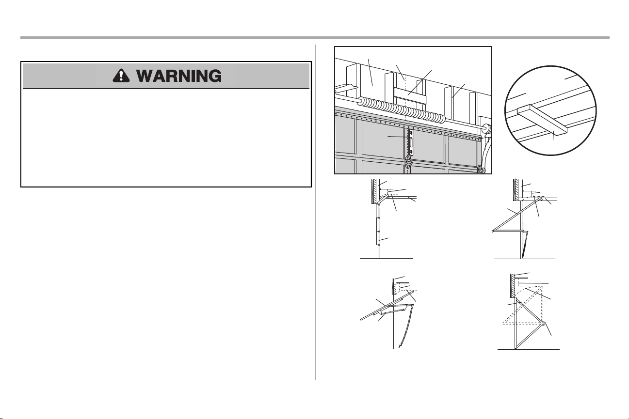
STEP 1 Determine the header bracket location
To prevent possible SERIOUSINJURY or DEATH:
• Header bracket MUST be RIGIDLY fastened to structural support on header wall or ceiling,
otherwise garage door might NOT reverse when required. DO NOT install header bracketover
drywall.
• Concreteanchors MUST be used if mounting header bracketor 2x4 into masonry.
• NEVER tryto loosen, move or adjustgarage door, springs, cables,pulleys, brackets, or their
hardware, ALL of which are under EXTREME tension.
• ALWAYS call a trained door systems technician if garage door binds, sticks, or is out of balance.
An unbalanced garage door might NOT reverse when required.
Installation procedures vary according to garage door types.Follow the instructionswhich apply to your
door.
1. Close the door and mark the inside vertical centerline of the garage door.
2. Extend the line onto the header wall above the door.
You can fasten the header bracket within4 feet (1.22 m) of the left or right of the door
center only if a torsionspring or center bearingplate is in the way; or you can attach it to
the ceiling when clearance is minimal.(It may be mountedon the wall upside down if
necessary, to gain approximately 1/2" (1 cm).
Ifyou need to install the header bracketon a 2x4 (on wall or ceiling), use lag screws (not
provided) to securely fasten the 2x4 to structural supports.
3. Open your door to the highest point of travel as shown.Draw an intersecting horizontal line on
the header wall 2" (5 cm) above the high point :
l
2" (5 cm) above the high point for sectional door and one-piece door with track.
l
8" (20 cm) above the high point for one-piece door without track.
Thisheight will provide travel clearance for the top edge of the door. NOTE:If the total number of inches
exceeds the height available in your garage, use the maximum height possible, or refer to page 12 for
ceiling installation.
11
Page 13
Installation
HARDWARE
Lag Screw 5/16"-9x1-5/8"
UP
Wall Mount
Optional Mounting
Holes
Vertical
Centerline of
Garage Door
(Header Wall)
Header
Bracket
2x4 Structural
Support
Door Spring
(Garage Door)
Highest Point
of Garage
Door Travel
Horizontal
Line
Lag Screw
5/16"-9x1-5/8"
UP
(Header Wall)
Ceiling Mounting
Holes
(Finished
Ceiling)
Vertical
Centerline of
Garage Door
Header
Bracket
6" (15 cm)
Maximum
Door Spring
(Garage Door)
Lag Screw
5/16"-9x1-5/8"
STEP 2 Install the header bracket
You can attach the header bracket either to the wall above the garage door, or to the ceiling.Follow the
instructions which will work bestfor your particular requirements.Do not install the header bracket over
drywall. If installing into masonry, use concrete anchors (not provided).
OPTION A WALL INSTALLATION
1. Centerthe bracket on the verticalcenterline with the bottomedge of the bracket on the
horizontal line as shown.
2. Mark the vertical set of bracketholes. Drill 3/16" pilot holes and fasten the bracketsecurely to a
structural support with the hardware provided.
OPTION B CEILING INSTALLATION
1. Extend the vertical centerline onto the ceiling as shown.
2. Center the bracketon the vertical mark, no more than 6" (15 cm) from the wall. Make sure the
arrow is pointing away fromthe wall. The bracketcan be mounted flush against the ceiling
when clearance is minimal.
3. Mark the side holes.Drill 3/16" pilot holes and fasten bracketsecurely to a structural support
withthe hardware provided.
12
Page 14
Installation
HARDWARE
Clevis Pin 5/16"x1-1/2"
Ring Fastener
Clevis Pin
5/16"x1-1/2"
Ring Fastener
Connected Disconnected
One-piece
door
without
tracks
All other
door types
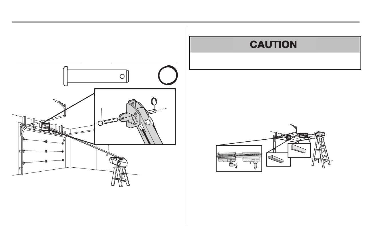
STEP3 Attach the rail to the header bracket
1. Align the rail withthe header bracket.Insertthe clevispin through the holes in the header
bracketand rail. Secure with the ring fastener.
NOTE: Use the packing material as a protective base for the garage door opener.
STEP 4 Position the garage door opener
To prevent damage to garage door, rest garage door opener rail on 2x4 placed on top section of
door.
1. Removethe packing material and lift the garage door opener onto a ladder.
2. Fully open the door and place a 2x4 (laid flat)under the rail. For one-piece doors without
tracks,lay the 2x4 on it's side.
NOTE: A 2x4 is ideal for setting the distancebetween the rail and the door. If the ladder is not tall
enough you will need help at this point. If the door hits the trolley when it is raised, pull the trolley release
arm down to disconnectthe inner and outer trolley. Slide the outer trolley toward the garage door
opener. The trolley can remain disconnected until instructed.
13
Page 15

+PUVCNNCVKQP
56'2 *CPI VJG ICTCIG FQQT QRGPGT
7R DYRLG SRVVLEOH 6(5,286 ,1-85< IURPD IDOOLQJ JDUDJH GRRU RSHQHU IDVWHQ LW 6(&85(/< WR
VWUXFWXUDO VXSSRUWVRI WKH JDUDJH &RQFUHWHDQFKRUV0867EH XVHG LI LQVWDOOLQJ $1< EUDFNHWVLQWR
PDVRQU\
*CPIKPI VJG ICTCIG FQQT QRGPGT YKNN XCT[ FGRGPFKPI QP [QWT ICTCIG $GNQY CTG VJTGG GZCORNG
KPUVCNNCVKQPU ;QWT KPUVCNNCVKQP OC[ DG FKHHGTGPV(QT #.. KPUVCNNCVKQPU VJG ICTCIG FQQT QRGPGT /756DG
EQPPGEVGF VQ UVTWEVWTCN UWRRQTVU6JG KPUVTWEVKQPU KNNWUVTCVGQPG QH VJG GZCORNGUDGNQY
Finished Ceiling
HARDWARE
Lag Screw 5/16"-9x1-5/8"
Unfinished Ceiling
Lock Washer
5/16"-18
Nut 5/16"-18
1P HKPKUJGF EGKNKPIUWUG VJG NCI UETGYUVQ CVVCEJ C UWRRQTV DTCEMGVPQV RTQXKFGF VQ VJG
UVTWEVWTCN UWRRQTVUDGHQTG KPUVCNNKPI VJG ICTCIG FQQT QRGPGT
/CMG UWTG VJG ICTCIG FQQT QRGPGT KU CNKIPGF YKVJVJG JGCFGT DTCEMGV /GCUWTG VJG FKUVCPEG
HTQOGCEJ UKFG QH VJG ICTCIG FQQT QRGPGT VQ VJG UWRRQTVDTCEMGV
%WVDQVJ RKGEGUQH VJG JCPIKPI DTCEMGV VQ TGSWKTGF NGPIVJU
#VVCEJ VJG GPF QH GCEJ JCPIKPI DTCEMGVVQ VJG UWRRQTVDTCEMGV YKVJCRRTQRTKCVG JCTFYCTG PQV
RTQXKFGF
#VVCEJ VJG ICTCIG FQQT QRGPGT VQ VJG JCPIKPI DTCEMGVU YKVJVJG JGZ DQNVU NQEM YCUJGTU CPF
PWVU
4GOQXG VJG Z CPF OCPWCNN[ENQUGVJG FQQT +HVJG FQQT JKVU VJG TCKNTCKUG VJG JGCFGT DTCEMGV
1
Finished
Ceiling
Lag Screw
5/16"9x1-5/8"
4
(not
provided)
(not provided)
Lag Screw
5/16"9x1-5/8"
5
Hex Bolt
5/16"- 18x7/8"
Lock Washer
5/16"-18
Nut 5/16"-18
2
6
3
Hex Bolt 5/16"- 18x7/8"
42
14
Page 16

Installation
NOTICE
STEP 6 Install the light bulbs
To prevent possible OVERHEATING of the endpanel or light socket:
l
DO NOTuse short neck or specialty light bulbs.
l
DO NOTuse halogen bulbs. Use ONLY incandescent.
To prevent damage to the opener:
l
DO NOTuse bulbs larger than 100W.
l
ONLY use A19 size bulbs.
1. Install a 100 watt maximum light bulb in each socket.Light bulb size should be A19, standard
neckonly. The lights will turn ON and remain lit for approximately 4-1/2 minutes when power is
connected.Then the lights will turn OFF.
2. Insertbottomlens tabs into slotson chassis.Tilt towardschassisto engage top tabs,then drop
down gently into place (see illustration).
3. To remove,depressboth top lens tabs.Tilt lens slightly outward and down, then pull out to
clear bulbs. Use care to avoid snapping offbottomlens tabs.
4. UseA19,standard neck garage door opener bulbs for replacement.
NOTE: Use only standard light bulbs. The use of short neck or specialitylight bulbs may overheat the
endpanel or light socket.
STEP 7 Attach the emergency release rope and handle
To prevent possible SERIOUSINJURY or DEATHfrom a falling garage door:
• Ifpossible, use emergencyrelease handle to disengage trolley ONLY when garage door is
CLOSED. Weak or broken springs or unbalanced door could resultin an open door falling rapidly
and/or unexpectedly.
• NEVER use emergency release handle unless garage doorwayis clear of persons and
obstructions.
• NEVER use handle to pull door open or closed. If rope knot becomes untied, you could fall.
1. Insertone end of the emergencyrelease rope through the handle. Make sure that “NOTICE”is
right side up. Tie a knot at least 1 inch (2.5 cm) from the end of the emergency release rope.
2. Insertthe other end of the emergency release rope through the hole in the trolley release arm.
Mount the emergencyrelease within reach, but at least6 feet (1.83 m) above floor, avoiding
contactwith vehicles to prevent accidental release and secure with a knot.
NOTE: If it is necessaryto cut the emergency release rope, seal the cut end with a match or lighter to
prevent unraveling. Ensure the emergencyrelease rope and handle are above the top of all vehicles to
avoid entanglement.
15
Page 17

Installation
A horizontal and vertical reinforcementis needed for
li
ghtweight garage doors (fi
berglass, aluminum, steel,
doors with glass panel, etc.) (not provided).
A horizontal reinforcement brace should be long
enough to be secured to two or three vertical supports.
A vertical reinforcement brace should cover the height
of the top panel.
FIGURE 1
Self-Threading Screw
1/4"-14x5/8"
HARDWARE
FIGURE 2
FIGURE 4
FIGURE 5
FIGURE 3
Vertical
Reinforcement
Vertical Centerline
of Garage Door
UP
Door Bracket
Vertical Reinforcement
Vertical Centerline
of Garage Door
Bolt 5/16"-18x2"
(not provided)
Lock Washer 5/16"
Nut 5/16"-18
Door Bracket
UP
Vertical
Centerline
of Garage
Door
UP
Vertical Centerline of
Garage Door
Bolt 5/16"-18x2"
(not provided)
UP
Inside Edge of Door or
Reinforcement Board
Self-Threading Screw
1/4"-14x5/8"
Self-Threading
Screw
1/4"-14x5/8"
STEP 8 Install the door bracket
Fiberglass,aluminum or lightweightsteel garage doors WILLREQUIRE reinforcement BEFORE
installation of door bracket.Contactyour door manufacturer for reinforcementkit.
Figure 1 shows one piece of angle iron as the horizontal brace. For the vertical brace, 2 pieces of angle
iron are used to create a U-shaped support.The best solution is to checkwith your garage door
manufacturer for an opener installation door reinforcementkit.
NOTE: Many door reinforcement kitsprovide for direct attachment of the clevispin and door arm.In this
case you will not need the door bracket; proceed to the next step.
OPTION A SECTIONALDOORS
1. Center the door bracket on the previously marked vertical centerline used for the header
bracketinstallation. Note correctUP placement, as stamped inside the bracket.
2. Position the top edge of the bracket2"-4" (5-10 cm) below the top edge of the door, OR
3. Mark,drill holes and install as follows, depending on your door’s construction:
directlybelow any structuralsupport across the top of the door.
Metal or light weight doors usinga vertical angle iron brace between the door panel support
and the doorbracket:
• Drill 3/16" fastening holes. Secure the door bracketusing the two self threading screws.
(Figure 2)
• Alternately,use two 5/16" bolts,lockwashers and nuts (not provided). (Figure 3)
Metal,insulated or light weight factory reinforced doors:
• Drill 3/16" fastening holes. Secure the door bracketusing the self-threading screws.
(Figure 4)
Wood Doors:
• Usetop and bottomor side to side door bracketholes. Drill 5/16" holes through the door and
secure bracketwith 5/16"x2" carriage bolts,lockwashers and nuts (not provided). (Figure 5)
NOTE: The 1/4"-14x5/8" self-threading screws are not intended for use on wood doors.
16
Page 18

Installation
For a door with no exposed
framing, or for the optional
installation, use lag screws
5/16"x1-1/2" (not provided)
to fasten the door bracket.
Vertical
Centerline
of Garage
Door
Optional
Placement
of Door
Bracket
Door Bracket
Header Bracket
Header Wall
2x4 Support
(Finished Ceiling)
Door
Bracket
Top of Door
(Inside Garage)
Top Edge of
Door
Optional
Placement
Optional
Placement
Top
Edge
of Door
Top of Door
(Inside
Garage)
Door
Bracket
Carriage Bolt 5/16"x2"
(not provided)
Nut 5/16"-18
Lock Washer 5/16"
Metal Door
Wood Door
Self-Threading
Screw 1/4"-14x5/8"
STEP 8 Install the door bracket (continued)
OPTION B ONE-PIECEDOORS
1. Center the door bracket on the top of the door, in line with the header bracketas shown.
2. Mark either the left and right,or the top and bottomholes.
Metal Doors:
• Drill 3/16" pilot holes and fasten the bracketwiththe self-threading screwsprovided.
Wood Doors:
• Drill 5/16" holes and use 5/16"x2" carriage bolts,lockwashers and nuts (not provided) or 5/16"x11/2" lag screws(not provided) depending on your installation needs.
NOTE: The door bracketmay be installed on the top edge of the door if required for your installation.
(Refer to the dotted line optional placement drawing.)
17
Page 19

Installation
HARDWARE
Hex Bolt 5/16"-18x7/8"
Nut 5/16"-18
Lock
Washer
5/16"
-18
Clevis Pin 5/16"x1"
Clevis Pin 5/16"x1-1/4"
Ring Fastener
Straight
Door Arm
Curved
Door
Arm
(Groove
facing
out)
CORRECT
Straight
Door
Arm
Curved
Door
Arm
INCORRECT
Lock Washer
5/16" -18
Nut
5/16"-18
Hex Bolt 5/16"-18x7/8"
Clevis Pin 5/16"x1-1/4"
Ring Fastener
Clevis Pin
5/16"x1"
STEP 9 Connect the door arm to the trolley
Installation will vary according to the garage door type. Follow the instructionswhich apply to your door.
OPTION A SECTIONAL DOORS
IMPORTANT: The groove on the straight door arm MUST face away from the curved door arm.
1. Close the door. Disconnectthe trolley by pulling the emergencyrelease handle.
2. Attach the straightdoor arm to the outer trolley using the clevis pin. Secure withthe ring
fastener.
3. Attach the curved door arm to the door bracketusing the clevispin. Secure with the ring
fastener.
4. Bring arm sections together. Find two pairs of holes that line up and join sections.Selectholes
as far apart as possible to increase door arm rigidity and attachusing the bolts, nuts, and lock
washers.
5. Pull the emergency release handle toward the garage door opener until the trolley release
arm is horizontal.The trolley will re-engage automaticallywhen the garage door opener is
activated.
NOTE: If the holes in the curved door arm and the straight door arm do not align, reverse the straight
door arm, selecttwo holes (as far apart as possible) and attach using bolts , nuts,and lock washers . If the
straight door arm is hanging down too far, you may cut 6 inches (15 cm) from the solid end.
18
Page 20

Installation
HARDWARE
Hex Bolt 5/16"-18x7/8"
Nut 5/16"-18
Lock
Washer
5/16" -18
Clevis Pin 5/16"x1"
Clevis Pin 5/16"x1-1/4"
Ring Fastener
FIGURE 1: Door Closed
FIGURE 2
Inner Trolley
Outer Trolley
Open Door
Door with Bacward Slant (Incorrect)
Door Arm
Nut
Ring
Fastener
Ring Fastener
Lock Washer
Clevis Pin
5/16"x1-1/4"
Hex Bolt
Clevis Pin
5/16"x1"
One-Piece Door without Track
One-Piece Door with Track
Ring
Fastener
Ring Fastener
Nut
Lock Washer
Clevis Pin
5/16"x1-1/4"
Hex Bolt
Clevis Pin
5/16"x1"
CORRECT
Straight
Door
Arm
(Groove
facing
out)
Curved
Door
Arm
INCORRECT
Straight
Door
Arm
Curved
Door
Arm
STEP 9 Connect the door arm to the trolley (continued)
OPTION B ONE-PIECE DOORS
1. Assemble the doorarm, Figure 1:
IMPORTANT: The groove on the straight door arm MUST face away from the curved door arm.
• Fasten the straightand curved door arm sectionstogether to the longest possible length (with a 2 or 3
hole overlap).
• Withthe door closed,connect the straight door arm section to the door bracketwith the 5/16"x1-1/4"
clevispin. Secure with a ring fastener.
2. Adjustment procedures:
• On one-piece doors, before connecting the door arm to the trolley,the travel limits must be adjusted.
Limit adjustment screws are located on the leftside panel as shown on page 28. Follow adjustment
procedures below.
• Open door adjustment: Decrease UP travel limit
n
Turn the UP limitadjustment screw counterclockwise4 turns.
n
Press the door control push button.The trolley will travel to the fully open position.
n
Manually raise the door to the open position (parallel to the floor), and lift the door arm to the
trolley.The arm should touch the trolley justin the back of the door arm connector hole. Ifthe
arm does not extend far enough, adjust the limit further.One full turn equals 2" (5 cm) of trolley
travel.
• Closed door adjustment : Decrease DOWN travel limit
n
Turn the DOWNlimit adjustmentscrewclockwise 4 complete turns.
n
Press the door control push button.The trolley will travel to the fully closed position.
n
Manually close the door and lift the door arm to the trolley.The arm should touch the trolley
justahead of the door arm connector hole. Ifthe arm is behind the connector hole, adjust the
limitfurther. One full turn equals 2" (5 cm)of trolley travel.
3. Connect the door arm to the trolley:
• Close the door and join the curved arm to the connector hole in the trolley with the remaining clevis pin.
Itmay be necessaryto liftthe door slightly to make the connection. Secure with a ring fastener.
• Run the opener through a complete travelcycle.Ifthe door has a slight “backward” slant in full open
position as shown in the illustration, decrease the UP limit until the door is parallel to the floor
(Figure 2).
NOTE: A slight backward slant will cause unnecessary bucking and/or jerking operation as the door is
being opened or closed from the fully open position. See page 28 for adjustments.
19
Page 21

Installation
HARDWARE
Scre
w
6ABx1-1/4" (2)
Drywall
Anchors
(2)
Screw
6-32x1"
(2)
7/16" (11 mm) Top Mounting
Hole
Bottom Mounting
Hol
e
Top Mounting
Hole
Bottom Mounting
Hole
DRYWALL
GANG BOX
6-32x1"
6ABx1-1/4"
Drywall Anchor
DRYWALL
GANG BOX
6-32x1"
6ABx1-1/4"
Drywall Anchor
STEP10 Install the door control
To prevent possible SERIOUSINJURY or DEATHfrom electrocution:
• Be sure power is NOT connected BEFORE installing door control.
• ConnectONLY to 24 VOLT low voltage wires.
To prevent possible SERIOUSINJURY or DEATHfrom a closing garage door:
• Install door control within sight of garage door, out of reach of children at a minimum height of 5
feet(1.5 m), and away fromALL moving partsof door.
• NEVER permit children to operate or play with door control push buttons or remote control
transmitters.
• Activate door ONLY when it can be seen clearly,is properly adjusted,and there are no
obstructions to door travel.
• ALWAYS keep garage door in sight until completelyclosed.NEVER permit anyone to crosspath
of closing garage door.
Install the door control within sight of the door at a minimum height of 5 feet (1.5 m) where small children
cannot reach,and away from the moving parts of the door. For gang box installationsit is not necessary
to drill holes or install the drywall anchors. Use the existing holes in the gang box.
NOTE: Your product may look different than the illustrations.
Connect the door controlwires:
1. Strip 7/16" (11 mm) of insulation from one end of bell wire and connect to the two screw
terminalson backof door control by color: white wire to WHT (1) and white/red wire to the RED
(2). Ifyour garage is pre-wired for the door control, choose any two wires to connect,note
which wires are used so the correct wires are connected to the garage door opener in a later
step.
Installthe Multi-FunctionDoorControl:
1. Removecover by gently prying at the top of the cover with a small flathead screwdriver.
2. Mark the location of the bottom-mountinghole and drill a 5/32 inch (4 mm) hole.
3. Install the bottomscrew,allowing 1/8 inch (3 mm) to protrude from the wall.
4. Position the bottomhole of the door control over the screw and slide down into place.
5. Mark and drill the top hole.
6. Attach the top screw.
OR
Installthe DoorControl Button:
1. Mark and drill 5/32 inch (4 mm) hole(s).
2. Fasten door control button to wall with screws.
20
Page 22

Installation
HARDWARE
Ins
ulated
Staple
(Not Shown)
Staple
RED
WHITE
WHITE
GREY
7/16" (11 mm)
2
3
1
STEP 11 Wire the door control to the garage door opener
1. Run the whiteand red/white wire from the door control to the garage door opener. Attachthe
wire to the wall and ceiling with the staple (notapplicable for gang box or pre-wired
installations).Do not pierce the wire withthe staple as this may cause a short or an open
circuit.
2. Strip 7/16 inch (11 mm) of insulation fromthe end of the wire near the garage door opener.
3. Connectthe wire to the red and white terminals on the garage door opener. Ifyour garage is
pre-wired make sure you use the same wires that are connected to the door control. To insert
or release wires from the terminal, push in the tab with screwdriver tip.
STEP 12 Attach the warning labels
1. Attach the entrapment warning label on the wall near the door control withtacksor staples.
2. Attach the manual release/safetyreverse test label in a visible location on the inside of the
garage door.
21
Page 23

Installation
Safety Reversing Sensor
6" (15 cm) max. above floor
Invisible Light Beam
Protection Area
HARDWARE
Carriage Bolt
1/4"-20x1/2"
Wing Nut
1/4"-20
No more
than 6 inches
(15 cm)
Carriage Bolt
1/4"-20x1/2"
Wing Nut
1/4"-20
1
2
3
STEP 13 Install the Protector System
Be sure power is NOT connected to the garage door opener BEFORE installing the safetyreversing
sensor.
To prevent SERIOUSINJURY or DEATHfrom closing garage door:
• Correctlyconnectand align the safetyreversing sensor. This required safetydevice MUST NOT be
disabled.
• Install the safety reversing sensor so beam is NO HIGHERthan 6" (15 cm) above garage floor.
The safety reversingsensormust be connected and aligned correctly before the garage door
openerwillmove inthe down direction.
IMPORTANT INFORMATION ABOUTTHE SAFETY REVERSING SENSOR
When properly connected and aligned, the sensor will detectan obstacle in the path of itselectronic
beam. The sending eye (with an amber indicator light) transmitsan invisible light beam to the receiving
eye (witha green\ indicator light). If an obstruction breaks the light beam while the door is closing, the
door will stop and reverse to full open position,and the opener lights will flash10 times.
The unitsmust be installed inside the garage so that the sending and receiving eyes face each other
acrossthe door, no more than 6" (15 cm) above the floor.Either can be installed on the left or right of the
door as long as the sun never shines directlyinto the receiving eye lens.
The mounting bracketsare designed to clip onto the track ofsectional garage doors withoutadditional
hardware.
Ifit is necessary to mount the units on the wall,the bracketsmustbe securely fastened to a solid surface
suchas the wall framing. Extension brackets(see accessories) are available if needed. Ifinstalling in
masonryconstruction, add a piece of wood at each location to avoid drilling extra holes in masonry if
repositioning is necessary.
The invisible light beam path mustbe unobstructed.No part of the garage door (or door tracks,springs,
hinges, rollers or other hardware) may interrupt the beam while the door is closing.
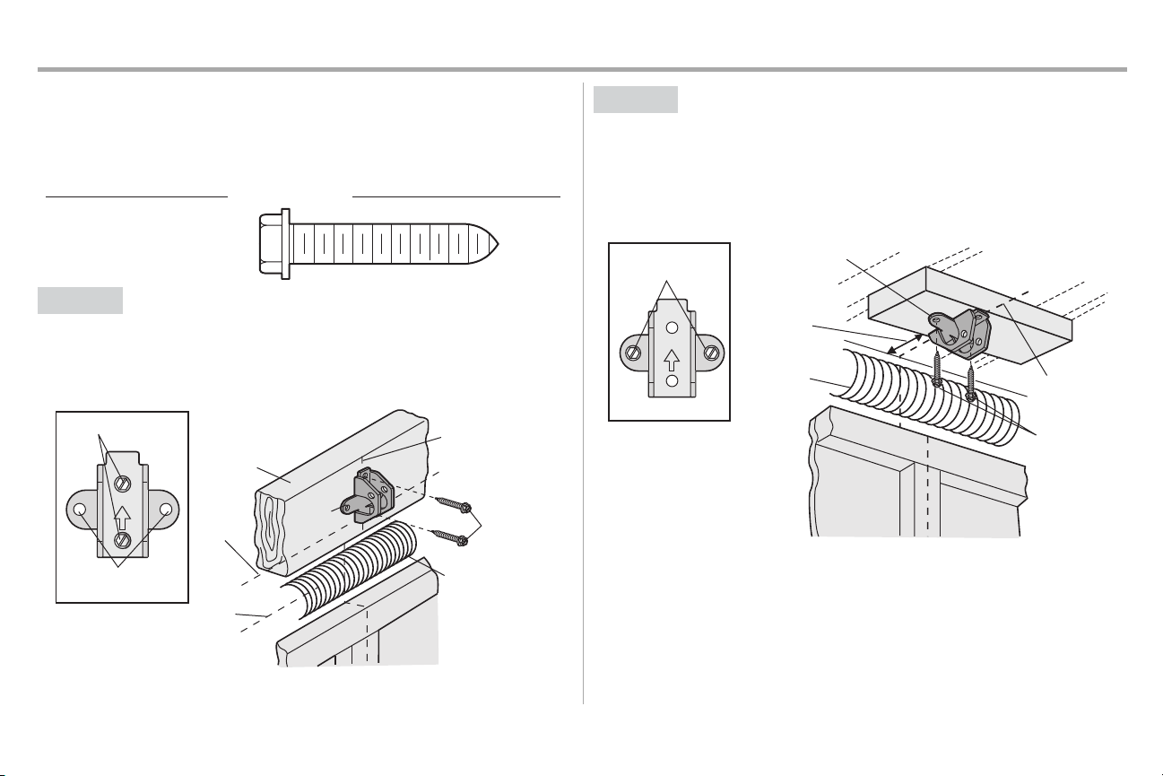
®
The safety reversing sensors can be attached to the door track,the wall, or the floor. The sensorsshould
be no more than 6 inches (15 cm) above the floor. If the door trackwill not support the sensor bracketa
wall installation is recommended. Choose one of the following installations.
OPTION A DOORTRACKINSTALLATION
1. Slide the curved arms of the sensor bracket around the edge of the door track.Snap into place
so that the sensor bracketis flush againstthe track.
2. Slide the carriage bolt into the slot on each sensor.
3. Insertthe bolt through the hole in the sensor bracketand attach with the wing nut. The lenses
on both sensors should point toward each other. Make sure the lens is not obstructed by the
sensor bracket.
Facingthe door from inside the garage
22
Page 24

Installation
(Not provided)
No more than
6 inches (15 cm)
1
2
Inside
G
arage
Wall
(Not provided)
Lens
Carriage Bolt
1/4"-20x1/2"
Wing Nut
1/4"-20
3
4
I
nsid
e
G
arage
Wa
l
l
(Not provided)
1 2
Carriage Bolt
1/4"-20x1/
2"
Wing Nut
1/4"-20
3
4
STEP 13 Install the Protector System®(continued)
OPTION B WALLINSTALLATION
Ifadditional clearance is needed an extension bracket(not provided) or wood blockscan be used. Make
sure each brackethas the same amount of clearance so they will align correctly.
1. Position the sensor bracketagainst the wall with the curved armsfacing the door. Make sure
there is enough clearance for the beam to be unobstructed.Mark holes.
2. Drill 3/16 inch pilot holes for each sensor bracketand attach the sensor brackets to the wall
using lag screws(not provided).
3. Slide the carriage bolt into the slot on each sensor.
4. Insertthe bolt through the hole in the sensor bracketand attach with the wing nut. The lenses
on both sensors should point toward each other. Make sure the lens is not obstructed by the
sensor bracket.
OPTION C FLOORINSTALLATION
Usean extension bracket (not provided) or wood blockto raise the sensor bracketif needed.
1. Carefullymeasure the position of both sensor bracketsso they will be the same distancefrom
the wall and unobstructed.
2. Attach the sensor bracketsto the floor using concrete anchors (not provided).
3. Slide the carriage bolt into the slot on each sensor.
4. Insertthe bolt through the hole in the sensor bracketand attach with the wing nut. The lenses
on both sensors should point toward each other. Make sure the lens is not obstructed by the
sensor bracket.
23
Page 25

Installation
HARDWARE
Ins
ulated
Staple
(Not Shown)
Staple
7/16" (11 mm)
WHITE
WHITE
GREY
RED
1
2
3
STEP 14 Wire the Safety Reversing Sensors
Ifyour garage already has wires installed for the safetyreversing sensors, proceed to page 25.
OPTION A
1. Run the wire fromboth sensors to the garage door opener. Attach the wire to the wall and
2. Strip 7/16 inch (11 mm) of insulation fromeach set of wires. Separate the wires. Twistthe white
3. Insertthe white wires into the white terminal on the garage door opener. Insert the white/black
INSTALLATION WITHOUTPRE-WIRING
ceiling with the staples.
wires together. Twistthe white/blackwires together.
wires into the grey terminal on the garage door opener.To insert or remove the wires from the
terminal,push in the tab with a screwdriver tip.
24
Page 26

Installation
Safety reversing
sensor wires
Pre-installed
wires
White
White/Black
Yellow (for example)
Purple (for example)
Not Provided
Pre-installed wires
Safety reversing
sensor wires
7/16" (11 mm)
Yellow
Purple
1
3
4
7/16"
(11 mm)
2
WHITE
WHITE
RED
GREY
Purple
(for
example)
Yellow
(for example)
To insert or remove the wires from
the terminal, push in the tab with a
screwdriver tip.
5
STEP 14 Wire the Safety Reversing Sensors (continued)
OPTION B PRE-WIREDINSTALLATION
1. Cutthe end of the safetyreversing sensor wire, making sure there is enough wire to reach the
pre-installed wires from the wall.
2. Separate the safetyreversing sensor wires and strip 7/16 inch (11 mm) of insulation from each
end. Choose twoof the pre-installed wires and strip 7/16 inch (11 mm) of insulation fromeach
end. Make sure that you choose the same color pre-installed wires for each sensor.
3. Connectthe pre-installed wires to the sensor wireswith wire nuts making sure the colors
correspond for each sensor. For example, the white wire would connectto the yellow wire and
the white/black wire would connectto the purple wire.
4. At the garage door opener, strip 7/16 inch (11 mm) of insulation fromeach end of the wires
previously chosen for the safetyreversing sensors.Twist the like-colored wires together.
5. Insertthe wires connected to the white safetysensor wires to the white terminal on the garage
door opener. Insertthe wires that are connected to the white/black safetysensor wires to the
grey terminal on the garage door opener.
25
Page 27

Installation
Ground Tab
Green
Ground
Screw
Ground
Wire
White Wire
Black
Wire
Black
Wire
STEP 15 Connect power
To prevent possible SERIOUSINJURY or DEATHfrom electrocution or fire:
• Be sure power is NOT connected to the opener, and disconnectpower to circuit BEFORE
removing cover to establish permanent wiring connection.
• Garage door installation and wiring MUSTbe in compliance with ALL local electrical and building
codes.
• NEVER use an extension cord, 2-wire adapter, or change plug in any way to make it fit outlet.Be
sure the opener is grounded.
To avoid installationdifficulties,do not activate the garage dooropenerat this time.
To reduce the riskof electric shock,your garage door opener has a grounding type plug with a third
grounding pin. This plug will only fitinto a grounding type outlet.If the plug doesn’t fitinto your outlet,
contacta qualified electrician to install the proper outlet.
THERE ARE TWO OPTIONS FOR CONNECTINGPOWER:
OPTION A
1. Plug in the garage door opener into a grounded outlet.
2. DO NOTrun garage door opener at thistime.
OPTION B
If permanent wiring is required by your local code,refer to the followingprocedure. To make a
permanent connection through the 7/8 inch hole in the top of the motorunit (according to local
code):
1. Removethe motor unit cover screwsand setthe cover aside.
2. Removethe attached 3-prong cord.
3. Connectthe black (line) wire to the screwon the brassterminal; the white (neutral) wire to the
4. Reinstallthe cover.
TYPICAL WIRING
PERMANENT WIRING
screwon the silver terminal; and the ground wire to the green ground screw.The opener
must be grounded.
26
Page 28

Installation
Green LED
Amber LED
If the receiving sensor is in direct sunlight,
switch it with sending sensor so it is on the
opposite side of the door.
(invisible light beam)
SENDING SENSOR RECEIVING SENSOR
RED
WHITE
WHITE
GREY
3
2
1
1
2
STEP 16 Ensure the safety reversing sensors are aligned
The doorwillnot close if the sensorshave not been installedand aligned correctly.
When the light beam is obstructed or misaligned while the door is closing,the door will reverse and the
garage door opener lights will flash ten times.Ifthe door is already open, it will not close. The sensors
can be aligned by loosening the wing nuts,aligning the sensors,and tightening the wing nuts.
Checkto make sure the LEDs in both sensors are glowing steadily. The LEDsin both sensors will glow
steadilyif they are aligned and wired correctly.
IFTHE AMBER LED ON THE SENDING SENSOR IS NOT GLOWING:
1. Make sure there is power to the garage door opener.
2. Make sure the sensor wire is not shorted/broken.
3. Make sure the sensor has been wired correctly:white wires to white terminal and white/black
wires to grey terminal.
IFTHE GREEN LED ON THE RECEIVING SENSOR IS NOT GLOWING:
1. Make sure the sensor wire is not shorted/broken.
2. Make sure the sensors are aligned.
27
Page 29

Adjustments
Cover Protection Bolt
Limit Adjustm
ent Screws
2-4"
(5-10 cm)
Left Side
Panel
Step 1 Adjust the UP and DOWN Travel Limits
Withouta properly installed safety reversal system,persons (particularly small children) could be
SERIOUSLY INJURED or KILLED by a closing garage door.
• Incorrectadjustmentof garage door travel limitswill interfere withproper operation of safety
reversal system.
• AfterANY adjustmentsare made, the safetyreversal systemMUST be tested. Door MUST reverse
on contactwith 1-1/2" (3.8 cm) high object(or 2x4 laid flat) on floor.
To prevent damage to vehicles,be sure fully open door provides adequate clearance.
Limit adjustment settings regulate the points at which the door will stop when moving up or down.
To operate the opener,pressthe Door Control push bar.
Runthe opener through a complete travel cycle.
• Does the door open and close completely?
• Does the door stayclosed and not reverse unintentionally when fully closed?
Ifyour door passesboth of these tests, no limitadjustmentsare necessary unless the reversing testfails
(AdjustmentStep 3, page 30).
Adjustmentprocedures are outlined below.Read the procedures carefully before proceeding to
AdjustmentStep 2. Use a screwdriver to make limit adjustments.
Run the opener through a complete travel cycle after each adjustment.
NOTE: Repeated operation of the opener during adjustmentprocedures may cause the motor to
overheat and shut off.Simply wait 15 minutes and try again.
NOTE: Anything interferes with the door’s upward travel, it will stop. If anything interferes with the door’s
downward travel (including binding or unbalanced doors), it will reverse.
HOW AND WHEN TO ADJUST THE LIMITS
• If the doordoes not open completely but opens at least five feet (1.5 m):
Increaseup travel. Turn the UP limitadjustment screw clockwise.One turn equals 2" (5 cm) of
travel.
NOTE: To prevent the trolley from hitting the cover protection bolt,keep a minimum distance of 2-4" (5 cm
- 10 cm) between the trolley and the bolt.
• If doordoes not open at least 5 feet (1.5 m):
Adjust the UP (open) force as explained in Adjustment Step 2.
• If the doordoes not close completely:
Increasedown travel. Turn the DOWN limit adjustmentscrewcounterclockwise.One turn equals 2"
(5 cm) of travel.
Ifdoor still won’t close completely and the trolley bumps into the pulley bracket,try lengthening the
door arm (page 18) and decreasing the down limit.
• If the opener reverses in fully closedposition:
Decrease down travel. Turn the DOWNlimit adjustmentscrewclockwise.One turn equals 2" (5 cm)
of travel.
• If the doorreverses when closingand there is no visible interference to travel cycle:
Ifthe opener lights are flashing, the Safety Reversing Sensors are either not installed,misaligned,
or obstructed.See page 27.
Testthe door for binding: Pull the emergency release handle. Manually open and close the door.If
the door is binding or unbalanced, call for a trained door systems technician. If the door is balanced
and not binding, adjustthe DOWN (close) force. See AdjustmentStep 2.
28
Page 30

Adjustments
Back Panel
Ante
nna
Open Force Close Force
Force Adjustment Screws
Step 2 Adjust the Force
Withouta properly installed safety reversal system,persons (particularly small children) could be
SERIOUSLY INJURED or KILLED by a closing garage door.
• Too much force on garage door will interfere withproper operation of safetyreversal system.
• NEVER increase forcebeyond minimum amount required to close garage door.
• NEVER use force adjustmentsto compensatefor a binding or stickinggarage door.
• Ifone control (force or travel limits)is adjusted, the other control may also need adjustment.
• AfterANY adjustmentsare made, the safetyreversal systemMUST be tested. Door MUST reverse on
contactwith 1-1/2" high (3.8 cm) object (or 2x4 laid flat) on floor.
Force adjustment controls are locatedon the backpanel of the motor unit. Force adjustment settings
regulate the amount of power required to open and close the door.
Ifthe forcesare set too light, door travel may be interrupted by nuisance reversalsin the down direction
and stops in the up direction. Weather conditions can affectthe door movement,so occasional
adjustmentmay be needed.
The maximum force adjustment range is about 3/4 of a complete turn.Do not force controls beyond
that point.
Turn force adjustment controls with a screwdriver.
NOTE: If anything interferes with the door’s upward travel, it will stop. If anything interferes with the door’s
downward travel (including binding or unbalanced doors), it will reverse.
HOW AND WHEN TO ADJUSTTHE FORCES
1. Test the DOWN (close) force
l
Grasp the door bottomwhen the door is abouthalfway through DOWN (close) travel. The door
should reverse. Reversal halfway through down travel does not guarantee reversal on a 11/2" (3.8 cm) obstruction.See Adjustment Step 3, page 30.If the dooris hardto hold or
doesn’t reverse, DECREASE the DOWN(close) force by turning the control
counterclockwise. Make small adjustmentsuntil the door reverses normally. After each
adjustment,run the opener through a complete cycle.
l
If the doorreverses during the down(close) cycle and the opener lights aren’t flashing,
INCREASE DOWN(close) force by turning the control clockwise.Make small adjustmentsuntil
the door completes a close cycle.After each adjustment,run the opener through a complete
travel cycle.Do not increase the force beyond the minimum amount required to close the door.
2. Test the UP (open) force
l
Grasp the door bottomwhen the door is abouthalfway through UP (open) travel.The door
should stop.If the door is hard to hold or doesn’t stop,DECREASE UP (open) force by
turning the control counterclockwise. Make small adjustmentsuntil the door stops easilyand
opens fully.After each adjustment,run the opener through a complete travel cycle.
l
If the doordoesn’t openat least 5 feet (1.5 m), INCREASE UP (open) force by turning the
control clockwise.Make small adjustmentsuntil door opens completely.Readjustthe UP limit if
necessary.After each adjustment,run the opener through a complete travel cycle.
29
Page 31

Adjustments
1 2
1
2
STEP 3 Test the Safety Reversal System
Withouta properly installed safety reversal system,persons (particularly small children) could be
SERIOUSLY INJURED or KILLED by a closing garage door.
• Safetyreversal systemMUST be tested every month.
• AfterANY adjustmentsare made, the safetyreversal systemMUST be tested. Door MUST reverse
on contactwith 1-1/2" (3.8 cm) high object(or 2x4 laid flat) on the floor.
1. Withthe door fullyopen, place a 1-1/2 inch (3.8 cm) board (or a 2x4 laid flat) on the floor,
centered under the garage door.
2. Press the remote control push button to close the door. The door MUSTreverse when it makes
contactwith the board.
Ifthe door stops and does not reverse on the obstruction,the down travel needs to be increased (refer to
AdjustmentStep 1). Repeat the test. When the door reverses upon contactwiththe 1-1/2 inch board,
remove the board and open/close the door 3 or 4 timesto test the adjustment. If the garage door opener
continues to fail the safetyreversal test,call a trained door systems technician.
STEP 4 Test the Protector System
Without a properly installed safetyreversing sensor, persons (particularly small children) could be
SERIOUSLY INJURED or KILLED by a closing garage door.
1. Open the door. Place the garage door opener carton in the path of the door.
2. Press the remote control push button to close the door. The door will not movemore than an
inch (2.5 cm),and the garage door opener lightswill flash 10 times.
The garage door opener will not close from a remote control if the LED in either safetyreversing sensor
is off (alerting you to the factthatthe sensor is misaligned or obstructed).Ifthe garage door opener
closesthe door when the safetyreversing sensor is obstructed (and the sensors are no more than 6
inches [15 cm] above the floor), call for a trained door systems technician.
®
30
Page 32

Operation
IMPORTANT SAFETYINSTRUCTIONS
To reduce the risk of SEVERE INJURY or DEATH:
1. READ AND FOLLOW ALL WARNINGS ANDINSTRUCTIONS.
2. ALWAYS keep remotecontrols out of reach ofchildren. NEVER permit children to operate or
play withgarage door control push buttonsor remote controls.
3. ONLY activate garage door when it can be seen clearly,it is properly adjusted, and there are
no obstructionsto door travel.
4. ALWAYS keep garage door in sight and away from people and objectsuntil completely
closed. NO ONE SHOULDCROSS THE PATH OF THE MOVING DOOR.
5. NO ONE SHOULD GO UNDERA STOPPED, PARTIALLY OPENED DOOR.
6. Ifpossible, use emergencyrelease handle to disengage trolley ONLY when garage door is
CLOSED. Use caution when using the release with the door opener. Weak or broken springs
or unbalanced door could resultin an open door falling rapidly and/or unexpectedly and
increasing the riskof SEVEREINJURYorDEATH.
7. NEVER use emergency release handle unless garage doorwayis clear of persons and
obstructions.
8. NEVER use handle to pull garage door open or closed. If rope knot becomesuntied, you
could fall.
9. AfterANY adjustmentsare made, the safetyreversal system MUST be tested.
10. Safetyreversal system MUST be tested every month.Garage door MUST reverse on
contactwith 1-1/2" (3.8 cm) high object (or a 2x4 laid flat)on the floor. Failure to adjustthe
garage door opener properly increasesthe risk of SEVERE INJURY or DEATH.
11. ALWAYS KEEP GARAGE DOOR PROPERLY BALANCED(see page 2). An improperly
balanced door may NOT reverse when required and could result in SEVERE INJURY or
DEATH.
12. ALL repairs to cables, spring assemblies and other hardware, ALL of which are under
EXTREME tension, MUSTbe made by a trained door systems technician.
13. ALWAYS disconnectelectricpower to garage door opener BEFORE making ANY
repairs or removing covers.
14. This operator system is equipped with an unattended operation feature.The door could
move unexpectedly.NO ONE SHOULD CROSS THE PATHOF THE MOVINGDOOR.
15. SAVE THESE INSTRUCTIONS.
31
Page 33

Operation
Push Bar
Lock
Button
Light
Button
Push
Button
Using Your Garage Door Opener
Your Security+®opener and hand-held remote control have been factory-setto a matching code which
changes witheach use, randomly accessing over 100 billion new codes. Your opener will operate with
up to eight Security+®remote controls and one Security+®KeylessEntry System.Ifyou purchase a new
remote,or if you wish to deactivate any remote,follow the instructionsin the Programming section.
Activate youropenerwith any of the following:
l
The Hand-Held Remote Control: Hold the large push buttondown until the door startsto move.
l
The Wall-Mounted Door Control: Hold the push button or bar down until the door startsto
move.
l
The KeylessEntry (See Accessories):Ifprovided with your garage door opener, it must be
programmed before use. See Programming.
Whenthe openeris activated (with the safety reversingsensorcorrectly installed andaligned)
1. Ifopen, the door will close. Ifclosed,it will open.
2. Ifclosing,the door will reverse.
3. Ifopening, the door will stop.
4. Ifthe door has been stopped in a partiallyopen position, it will close.
5. Ifobstructed while closing, the door will reverse. If the obstruction interruptsthe sensor beam,
the opener lightswill blink for five seconds.
6. Ifobstructed while opening, the door will stop.
7. Iffully open, the door will not close when the beam is broken. The sensor has no effectin the
opening cycle.
Ifthe sensor is not installed, or is misaligned, the door won’t close from a hand-held remote. However,
you can close the door withthe Door Control, the Outside Keylock,or KeylessEntry, if you activate them
until down travel is complete. If you release them too soon, the door will reverse.
The opener light will turn on under the following conditions: when the opener is initially plugged in; when
power is restored afterinterruption; when the opener is activated.
They will turn off automatically after 4-1/2 minutes.Bulb sizeis A19. Bulb power is 100 wattsmaximum.
Security+®light feature: Lightswill also turn on when someone walks through the open garage door.
Witha Multi-Function Door Control,this feature may be turned offas follows:With the opener lights off,
press and hold the light button for 10 seconds,until the light goes on, then off again. To restore this
feature,startwith the opener lightson, then press and hold the light button for 10 seconds until the light
goes off,then on again.
Using the Wall-Mounted Door Control
Door Control Button
Press the lighted push button to open or close the door. Press again to reverse the door during the
closing cycle or to stopthe door while it’sopening.
The Multi-FunctionDoor Control
Press the push bar/push buttonto open or close the door. Pressagain to reverse the door during the
closing cycle or to stopthe door while it’sopening.
Light Feature
Press the Light buttonto turn the opener light on or off.It will not control the opener lights when the door
is in motion.If you turn it on and then activate the opener, the light will remain on for 4-1/2 minutes. Press
again to turn it offsooner. The 4-1/2 minute interval can be changed to 1-1/2,2-1/2, or 3-1/2 minutes as
follows:
1. Press and hold the Lock button until the light blinks(about 10 seconds).A single blink
indicatesthat the timer is reset to 1-1/2 minutes.
2. Repeat the procedure and the light will blink twice,resetting the timerto 2-1/2 minutes.
3. Repeat again for a 3-1/2 minute interval, etc., up to a maximum offour blinksand 4-1/2
minutes.
Lock Feature
Designed to prevent operation of the door from handheld remote controls.However,the door will open
and close from the Door Control, the Outside Keylockand the KeylessEntry Accessories.
To activate, press and hold the Lockbutton for 2 seconds.The push bar light will flash as long as the Lock
feature is on.
To turn off,pressand hold the Lock button again for 2 seconds.The push bar light will stop flashing. The
Lockfeature will also turn off whenever the “Learn” button on the motor unit panel is activated.
32
Page 34

Operation
NOTICE
N
O
TICE
LIMIT CONTROLS
FORCE CONTROLS
To Open the Door Manually
To prevent possible SERIOUSINJURY or DEATHfrom a falling garage door:
• Ifpossible, use emergencyrelease handle to disengage trolley ONLY when garage door is
CLOSED. Weak or broken springs or unbalanced door could resultin an open door falling
rapidly and/or unexpectedly.
• NEVER use emergency release handle unless garage doorwayis clear of persons and
obstructions.
• NEVER use handle to pull door open or closed. If rope knot becomes untied, you could fall.
DISCONNECTTHE TROLLEY
1. The door should be fully closed if possible.
2. Pull down on the emergency release handle so the trolley release arm snaps to the vertical
position.The door can now be raised and lowered as often as necessary.
RECONNECT THE TROLLEY
1. Pull the emergency release handle toward the garage door opener so the trolley release arm
snaps to the horizontal position.
The trolley will reconnecton the next UP or DOWNoperation, either manually or by using the
door control or remote control.
Care of Your Opener
LIMIT ANDFORCE ADJUSTMENTS
Weather conditions may cause some minor changes in door operation requiring some re-adjustments,
particularly during the firstyear of operation. Pages28 and 29 refer to the limit and force adjustments.
Only a screwdriver is required. Follow the instructionscarefully.Repeat the safetyreverse test
(AdjustmentStep 3, page 30) after any adjustmentof limits or force.
MAINTENANCE SCHEDULE
Every Month
l
Manually operate door. If it is unbalanced or binding, call a trained door systemstechnician.
l
Checkto be sure door opens and closes fully.Adjust limits and/or force if necessary (see
pages 28 and 29).
l
Repeat the safetyreverse test.Make any necessary adjustments(see Adjustment Step 3).
Two Times a Year
l
Checkchain tension. Disconnecttrolley first.Adjustif necessary(see page 9).
Every Year
l
Oil door rollers, bearings and hinges. The opener does not require additional lubrication. Do
not grease the door tracks.
33
Page 35

Operation
Bell Wire
Sending Eye
Safety Reversing Sensor
(Amber Indicator Light)
Receiving Eye
Safety Reversing Sensor
(Green Indicator Light)
Safety Reversing
Sensor
“Learn”
Button
LED or
Diagnostic
LED
Having a Problem?
1. My door will not close and the light bulbs blink on my motor unit: The safety reversing
sensor must be connected and aligned correctly before the garage door opener will move
inthe down direction.
l
Verify the safetyreversing sensors are properly installed, aligned and free of any obstructions.
Refer to Installation Step 13: Install The Protector System®.
l
CheckdiagnosticLED for flashes on the motor unit then refer to the DiagnosticChart on the
following page.
2. My remotes willnot activate the door:
l
Verify your Multi-Function Door Control is not blinking.If it is blinking, deactivate the Lock Mode
following the instructions for Using the Multi-Function Door Control.
l
Reprogram remotes following the programming instructions.Refer to Programming.
l
Ifremote will still not activate your door, checkdiagnosticLED for flasheson motor unit then
refer to DiagnosticChart on the following page.
3. My door reverses for noapparent reason: Repeat safetyreverse testafter adjustmentsto
force or travel limits.The need for occasional adjustment for the force and limit settings is
normal. Weather conditionsin particular can affect door travel.
l
Manually checkdoor for balance or any binding problems.
l
Refer to Adjustment Step 2, Adjustthe force.
4. My door reverses for noapparent reason after fully closing and touching the floor: Repeat
safety reverse testafter adjustmentsto force or travel limits.The need for occasional
adjustmentfor the force and limit settingsis normal. Weather conditions in particular can affect
door travel.
l
Refer to Adjustment Step 1, Adjustthe UP and DOWN Travel Limits.Decrease down travel by
turning down limit adjustmentscrewclockwise.
5. My lights will not turnoff when dooris open:
l
The garage door opener is equipped with a security light feature. This feature activatesthe
light on when the safetyreversing sensor beam has been obstructed.Refer to Operation
section; Using the Wall-Mounted Door Control, Light Feature.
6. My motorunit hums briefly:
l
Firstverifythat the trolley is against the stop bolt.
l
Release the door from the opener by pulling the Emergency Release Rope.
l
Manually bring the door to a closed position.
l
Loosen the chain by adjusting the outer nut 4 to 5 turns.This relieves the tension.
l
Run the motor unitfrom the remote control or door control. The trolley should travel towards
the door and stop.Ifthe trolley re-engages with the door, pull the EmergencyRelease Rope to
disengage.
l
Decrease the UP travel by turning the UP Travel adjustmentscrew2 full turns away from the
arrow.
l
Re-tighten the outer nut so the chain is a 1/4" (6 mm) above the base of the rail. (When the
door is reconnected and closed, the chain will sag.This is normal.)
l
Ifthe trolley does not move away from the bolt,repeat the stepsabove.
34
Page 36

Operation
Your garage door opener is programmed with
self-diagnostic capabilities. The “Learn”
button/diagnostic LED will flash a number of times
then pause signifying it has found a potential issue.
Consult Diagnostic Chart below.
Installed
Safety Reversing
Sensor
“Learn”
Button
Safety Reversing
Sensor
Bell Wire
Diagnostics Located
on Motor Unit
LED or
Diagnostic
LED
Diagnostic Chart
1 Flash
Safetyreversing
sensorswire open
(broken or
disconnected).
OR
2 Flashes
Safetyreversing
sensorswire shorted
or black/white wire
reversed.
Symptom: One or both of the Indicator lights on the safety
reversing sensors do not glow steady.
l
Inspectsensor wires for a short (staple in wire), correct
wiring polarity (black/white wires reversed), broken or
disconnectedwires, replace/attach as needed.
l
Disconnect all wires from back of motor unit.
l
Removesensors from bracketsand shorten sensor wires
to 1-2 ft.(30-60 cm) from backeach of sensor.
l
Reattach sending eye to motor unit using shortened wires.
Ifsending eye indicatorlight glowssteadily,attachthe
receiving eye.
l
Align sensors, if the indicator lights glow replace the wires
for the sensors. If the sensor indicator lightsdo not light,
replace the safetyreversing sensors.
3 Flashes
Door control or wire
shorted.
4 Flashes
Safetyreversing
sensorsslightly
misaligned (dim or
flashing LED).
5 Flashes
Motor overheated or
possible RPM sensor
failure. Unplug to
reset.
6 Flashes
Motor Circuit Failure.
Replace Receiver
Logic Board.
35
Symptom: LED is not liton doorcontrol.
l
Inspectdoor control/wiresfor a short (staple in wire),
replace as needed.
l
Disconnect wires at door control, touch wires together. If
motor unit activates,
replace door control.
l
Ifmotor unit does not activate, disconnectdoor control
wires from motor unit.
Momentarilyshort acrossred and white terminals with
jumper wire. If motor unit
activates,replace door control wires.
Symptom: Sendingindicatorlight glows steadily, receiving
indicator light is dim or flashing.
l
Realign receiving eye sensor, clean lens and secure
brackets.
l
Verify door trackis firmlysecured to wall and does not
move.
Symptom: Motorhas over heated; the motor unit does not
operate or trolley is stuck on stop bolt= Motorunit hums briefly;
RPM Sensor= Short travel 6-8" (15-20 cm).
l
Unplug unit to reset.Try to operate motor unit, check
diagnostic code.
l
Ifit is still flashing 5 timesand motor unit moves 6-8" (15-20
cm),replace RPM sensor.
l
Ifmotor unit doesn’t operate, motor unit is overheated. Wait
30 minutes and retry.
Ifmotor unit still will not operate replace logic board.
Symptom: Motorunit doesn’t operate.
l
Replace logic board because motor rarely fails.
Page 37

Operation
LEARN LED
LEARN
Button
“click”
“click”
1
2
1
OR
OR
2
3
Programming
NOTICE: Ifthis Security+®garage door opener is operated with a non-rolling code transmitter, the
technical measure in the receiver of the garage door opener, which provides security against code-theft
devices,will be circumvented. The owner of the copyright in the garage door opener does not authorize
the purchaser or supplier of the non-rolling code transmitter to circumventthat technical measure.
PROGRAM A REMOTE CONTROL USING THE LEARN BUTTON
1. Locate the Learn Button.
2. Press and immediatelyrelease the Learn button. The Learn LEDwill glow steadyfor 30
seconds.Within 30 seconds...
3. Press and hold the button on the remote control that you wish to use.
Release the button when the garage door opener lights blink or twoclicksare heard.
When replacing the light lens cover, ensure the antenna wires are hanging straight down.
PROGRAMAREMOTECONTROLUSING THE MULTI-FUNCTION DOOR CONTROL
1. Press and hold the button on the hand-held remote*that you wish to operate your garage
door.
2. While holding the remote button,press and hold the LIGHT button on the Multi-Function Door
Control.Continue holding both buttons while you pressthe push bar on the Multi-Function
Door Control (all three buttons are held).
3. Release buttonswhen the motor unit lights blink.Ithas learned the code. If light bulbs are not
installed,two clicks will be heard.
To Erase the Memory
ERASE ALL REMOTE CONTROLS AND KEYLESS ENTRIES
1. Press and hold the learn button on garage door opener until the learn LED goes out
(approximately 6 seconds). All remote control and keylessentry codes are now erased.
Reprogram any accessory you wish to use.
*3-BUTTON REMOTES
Ifprovided with your garage door opener, the large button is factory programmed to operate it. Additional
buttonson any Security+®3-Button remote or compactremote can be programmed to operate other
Security+®garage door openers.
36
Page 38

Operation
1
2
3
2
1
3
Programming
To Add,Reprogram or Change a Keyless Entry PIN
NOTE: Your new Keyless Entry must be programmed to operate your garage door opener.
USING THE “LEARN”BUTTON
1. Press and release the “learn” button on motor unit.The learn indicator light will glow steadily
for 30 seconds.
2. Within 30 seconds,enter a four digit personal identificationnumber (PIN) of your choice on the
keypad.Then press and hold the ENTERbutton.
3. Release the button when the motor unit lights blink.It has learned the code. Iflight bulbs are
not installed,two clickswill be heard.
USING THE MULTI-FUNCTION DOOR CONTROL
1. Enter a four digit personal identification number (PIN)of your choice on the keypad.Then
press and hold ENTER.
2. While holding the ENTERbutton, pressand hold the LIGHT button on the Multi-Function Door
Control.Continue holding the ENTER and LIGHTbuttons while you pressthe push bar on the
Multi-Function Door Control (all three buttons are held).
3. Release buttonswhen the motor unit lights blink.Ithas learned the code. If light bulbs are not
installed,two clicks will be heard.
To change an existing,known PIN
Ifthe existing PIN is known, it may be changed by one person without using a ladder.
1. Press the four buttons for the presentPIN,then pressand hold the # button.
The opener light will blink twice.Release the # button.
2. Press the new 4-digit PINyou have chosen, then pressEnter. The motor unit lightswill blink
once when the PIN has been learned.
Testby pressing the new PIN, then pressEnter. The door should move.
To set a temporaryPIN
You may authorize accessby visitorsor service people witha temporary 4-digit PIN. After a programmed
number of hours or number of accesses, this temporary PINexpires and will no longer open the door.It
can be used to close the door even after it has expired. To set a temporary PIN:
1. Press the four buttons for your personal entry PIN(not the last temporary PIN),then pressand
hold the * button.
The opener light will blink three times.Release the button.
2. Press the temporary 4-digit PIN you have chosen,then press Enter.
The opener light will blink four times.
3. To set the number of hours this temporary PIN will work,press the number of hours (up to
255), then press *.
OR
1. To set the number of timesthis temporary PIN will work, press the number of times (up to 255),
then press #.
The opener light will blink once when the temporary PIN has been learned.
Testby pressing the four buttonsfor the temporary PIN,then press Enter. The door should move. Ifthe
temporary
PINwas setto a certain number of openings,remember that the testhas used up one opening. To clear
the temporary password, repeat steps1-3, setting the number of hours or times to 0 in step 3.
One ButtonClose: Opener can be closed by pressing only the ENTERbutton if the one button close
feature has been activated.This feature has been activated at the factory.To activate or deactivate this
feature press and hold buttons 1 and 9 for 10 seconds.The keypad will blink twice when the one button
close is active.The keypad will blink four timeswhen one button close is deactivated.
37
Page 39

Operation
The Remote Control Battery
To prevent possible SERIOUSINJURY or DEATH:
• NEVER allow small children near batteries.
• Ifbatteryis swallowed,immediately notifydoctor.
To reduce risk of fire, explosion or chemical burn:
• Replace ONLY with 3V2032 coin batteries.
• DO NOTrecharge, disassemble, heat above 212°F (100°C) or incinerate.
The lithium batteryshould produce power for up to 5 years.
To replace battery,use the visorclip or screwdriver blade to pry open the
caseas shown. Insert batterypositiveside up (+).
NOTICE: To complywith FCC and or Ind ustryCanada (IC) rules, adjustment or modificationsof th isreceiver and/or transmitterare
prohibited , exceptfor changing the code setting or rep lacingthe battery. THEREARENO OTHER USERSERVICEABLEPARTS.
Tested to Complywith FCC Standards FOR HOME OR OFFICEUSE. Operation is subject to the
following twoconditions: (1) thisdevice may not cause harmful interference, and (2) this device must
acceptany interference received, including interference thatmay cause undesired operation.
38
Page 40

7702CB Outside Quick Release:
Required for a garage with
NO access door.
41A5281 CLSS1 953D
7708CB
8 Foot (2.4 m) Rail
Extension:
10 Foot (3 m) Rail
Extension:
To allow an 8 foot (2.4 m) door
to open fully.
To allow an 10 foot (3 m) door
to open fully.
Laser Parking Assistant:
Park in the right spot every time!
A laser beam is activated by
your garage door opener and
projected on to the dashboard
of your vehicle to guide perfect
parking.
Installation Upgrade Kit:
The Installation Upgrade Kit
includes all components
needed to hang garage door
openers up to 24" (61 cm)
from the ceiling.
CLLAD CLDM1 956D
7710CB CLLP1 BIK01 940D
Extension Brackets:
(Optional) For safety reversing
sensor installation onto the wall
or floor.
Remote Light Control :
(Optional) For safety reversing
sensor installation onto the wall
or floor.
Garage Door Monitor:
Monitors the status of your
garage door from inside
your home.
System Surge Protector:
The Garage Door Opener
Surge Protector is designed to
protect Chamberlain garage
door openers against damage
from lighting and power
surges. Easy to install.
SECURITY✚® 3-Button Remote
Control :
Includes visor clip.
SECURITY✚® 3-Button Mini-Remote
Control :
With key ring and fastening strip.
SECURITY✚®
Keyless Entry :
Enables homeowner to operate garage
door opener from outside by entering a
password on a specially designed
keyboard. Also can add a temporary
password for visitors or service persons.
This temporary password can be limited
to a programmable number of hours or
entries.
Accessories
39
Page 41

Warranty
The Chamberlain Group,Inc. (“Seller”) warrants to the first retail purchaser of this product, for the residence in which
this product is originally installed, thatit is free from defect in materials and/or workmanship for a period of 1 YEAR
from the dateof purchase and that the MOTOR is free fromdefect in materials and/or workmanship for a period of 6
YEARS from the date of purchase. The proper operation of this product is dependent on your compliancewith the
instructions regarding installation, operation, maintenance andtesting. Failure to comply strictly with those instructions
will void this limited warranty in its entirety.
If, during the limited warranty period, this product appears to containa defectcovered by this limitedwarranty, call
1-800-528-9131, toll free, before dismantling this product. Thensend this product,pre-paid and insured, to our service
center for warranty repair. You will be advised of shipping instructions when you call. Please include a brief description
of the problem and a dated proof-of-purchase receipt with any product returned for warranty repair. Products returned
to Seller for warranty repair, which uponreceipt by Seller are confirmedto be defective and covered by this limited
warranty, will be repaired or replaced (at Seller’s sole option) at no cost to you and returnedpre-paid. Defective parts
will be repaired or replaced with new or factory-rebuilt parts at Seller’s sole option.
ALL IMPLIED WARRANTIES FOR TH E PROD UC T, INC LU DING BUT NOT LIMITED TO ANY IMPLIED
WARR AN TIES OF MERC HA NTABILITY AN D FITNESS FOR A PAR TICU LA R PURPOSE, AR E LIMITED IN
DURATION TO THE 1 YEAR LIMITED WARR AN TY PERIOD SET FORTH AB OVE EXCEPT THE IMPLIED
WARR AN TIES WITH R ESPECT TO THE MOTOR, WHICH A RE LIMITED IN DURATION TO THE 6 YEARS
LIMITED WAR RA NTY PERIOD FOR THE MOTOR, AND NO IMPLIED WARR AN TIES WILL EXIST OR APPLY
AFT ER SUCH PERIOD. Some States do not allow limitations on ho w long an implied warranty lasts, so the
above limitation may n ot apply to you.
THIS LIMITED WARR AN TY DOES NOT COVER NON-DEFECT DAMAGE, DAMAGE CAUSED BY IMPROPER
INSTALLA TION, OPERATION OR CA RE (INCLUD ING, BUT NOT LIMITED TO ABUSE, MISUSE, F AILU RE
TO PROVIDE REASONAB LE A ND NEC ESSARY MAIN TENANCE, UN AU THORIZED REPAIRS OR ANY
ALT ERATIONS TO THIS PR ODU CT), LA BOR CHARGES FOR REINSTALLING A REPAIRED OR
REPLACED UNIT, REPLA CEMENT OF BATTERIES AN D LIGHT BU LBS OR UNITS INSTALLED F OR N ONRESIDENTIAL USE. TH IS LIMITED WAR RA NTY DOES NOT COVER AN Y PROB LEMS WITH, OR RELA TING
TO, THE GARAGE DOOR OR GARAGE DOOR HARDWARE, INCLU DIN G BU T N OT LIMITED TO THE
DOOR SPRINGS, D OOR R OLLERS, DOOR ALIGNMENT OR H INGES. TH IS LIMITED WAR RA NTY ALSO
DOES NOT COVER AN Y PROBLEMS CAUSED B Y INTER FERENCE. A NY SERVICE CA LL T HA T
DETERMINES THE PROBLEM HAS BEEN CA USED BY A NY OF THESE ITEMS COU LD RESULT IN A F EE
TO YOU.
UNDER NO CIRCU MSTAN CES SHALL SELLER BE LIABL E FOR CON SEQUENT IAL, IN CIDENTA L OR
SPECIAL DAMAGES ARISING IN CONNECTION WITH USE, OR INABILITY TO USE, THIS PR ODU CT. IN NO
EVENT SHALL SELLER’S LIABILITY FOR BREAC H OF WARRANTY, B REACH OF CONTRACT,
NEGLIGENCE OR STRIC T LIABILITY EXCEED T HE COST OF T HE PRODUCT COVERED HER EBY. NO
PERSON IS AUTH ORIZED TO ASSUME FOR US A NY OT HER LIAB ILITY IN CON NECTION WITH TH E SALE
OF TH IS PRODUCT.
Somestates do not allow the exclusion or limitation of consequential, incidental or special damages, so theabove
limitation or exclusion may not apply to you. This limited warranty gives you specific legal rights, and you may also
have other rights which vary fromstate to state.
6 YEAR MOTOR LIMITED WARRANTY PD210D, PD212D, 248730, LW2000 & HD 200D
CHAMBERLAIN 1 YEAR L IMITED WARRANTY
CHAMBERLAIN®1 YEAR LIMITED WARR AN TY
The Chamberlain Group,Inc. (“Seller”) warrants to the first retail purchaser of this product, for the residence in which
this product is originally installed, thatit is free from defect in materials and/or workmanship for a period of 1 YEAR
from the dateof purchase and that the MOTOR is free fromdefect in materials and/or workmanship for the lifetimeof the
product. The proper operation of this product is dependenton your compliancewith the instructions regarding
installation, operation, maintenance andtesting. Failure to comply strictly with those instructions will void this limited
warranty in its entirety.
If, during the limited warranty period, this product appears to containa defectcovered by this limitedwarranty, call
1-800-528-9131, toll free, before dismantling this product. Thensend this product,pre-paid and insured, to our service
center for warranty repair. You will be advised of shipping instructions when you call. Please include a brief description
of the problem and a dated proof-of-purchase receipt with any product returned for warranty repair. Products returned
to Seller for warranty repair, which uponreceipt by Seller are confirmedto be defective and covered by this limited
warranty, will be repaired or replaced (at Seller’s sole option) at no cost to you and returnedpre-paid. Defective parts
will be repaired or replaced with new or factory-rebuilt parts at Seller’s sole option.
ALL IMPLIED WARRANTIES FOR TH E PROD UC T, INC LU DING BUT NOT LIMITED TO ANY IMPLIED
WARR AN TIES OF MERC HA NTABILITY AN D FITNESS FOR A PAR TICU LA R PURPOSE, AR E LIMITED IN
DURATION TO THE 1 YEAR LIMITED WARR AN TY PERIOD SET FORTH AB OVE EXCEPT THE IMPLIED
WARR AN TIES WITH R ESPECT TO THE MOTOR, WHICH A RE LIMITED IN DURATION TO THE LIFETIME
LIMITED WAR RA NTY PERIOD FOR THE MOTOR, AND NO IMPLIED WARR AN TIES WILL EXIST OR APPLY
AFT ER SUCH PERIOD. Some States do not allow limitations on ho w long an implied warranty lasts, so the
above limitation may n ot apply to you.
THIS LIMITED WARR AN TY DOES NOT COVER NON-DEFECT DAMAGE, DAMAGE CAUSED BY IMPROPER
INSTALLA TION, OPERATION OR CA RE (INCLUD ING, BUT NOT LIMITED TO ABUSE, MISUSE, F AILU RE
TO PROVIDE REASONAB LE A ND NEC ESSARY MAIN TENANCE, UN AU THORIZED REPAIRS OR ANY
ALT ERATIONS TO THIS PR ODU CT), LA BOR CHARGES FOR REINSTALLING A REPAIRED OR
REPLACED UNIT, REPLA CEMENT OF BATTERIES AN D LIGHT BU LBS OR UNITS INSTALLED F OR N ONRESIDENTIAL USE. TH IS LIMITED WAR RA NTY DOES NOT COVER AN Y PROB LEMS WITH, OR RELA TING
TO, THE GARAGE DOOR OR GARAGE DOOR HARDWARE, INCLU DIN G BU T N OT LIMITED TO THE
DOOR SPRINGS, D OOR R OLLERS, DOOR ALIGNMENT OR H INGES. TH IS LIMITED WAR RA NTY ALSO
DOES NOT COVER AN Y PROBLEMS CAUSED B Y INTER FERENCE. A NY SERVICE CA LL T HA T
DETERMINES THE PROBLEM HAS BEEN CA USED BY A NY OF THESE ITEMS COU LD RESULT IN A F EE
TO YOU.
UNDER NO CIRCU MSTAN CES SHALL SELLER BE LIABL E FOR CON SEQUENT IAL, IN CIDENTA L OR
SPECIAL DAMAGES ARISING IN CONNECTION WITH USE, OR INABILITY TO USE, THIS PR ODU CT. IN NO
EVENT SHALL SELLER’S LIABILITY FOR BREAC H OF WARRANTY, B REACH OF CONTRACT,
NEGLIGENCE OR STRIC T LIABILITY EXCEED T HE COST OF T HE PRODUCT COVERED HER EBY. NO
PERSON IS AUTH ORIZED TO ASSUME FOR US A NY OT HER LIAB ILITY IN CON NECTION WITH TH E SALE
OF TH IS PRODUCT.
Somestates do not allow the exclusion or limitation of consequential, incidental or special damages, so theabove
limitation or exclusion may not apply to you. This limited warranty gives you specific legal rights, and you may also
have other rights which vary fromstate to state.
LIFETIME MOTOR L IMITED WARRANTY PD 610D & PD612D
40
Page 42

Warranty
CHAMBERLAIN®TWO-YEAR LIMITED WARR AN TY
The Chamberlain Group,Inc. (“Seller”) warrants to the first retail purchaser of this product, for the residence in which
this product is originally installed, thatit is free from defect in materials and/or workmanship for a period of two years
from the dateof purchase and that the motor is free from defect in materials and/or workmanship for a period of ten
years from the date of purchase. The proper operation of this product is dependent on your compliance with the
instructions regarding installation, operation, maintenance andtesting. Failure to comply strictly with those instructions
will void this limited warranty in its entirety.
If, during the limited warranty period, this product appears to containa defectcovered by this limitedwarranty, call
1-800-528-9131, toll free, before dismantling this product. Thensend this product,pre-paid and insured, to our service
center for warranty repair. You will be advised of shipping instructions when you call. Please include a brief description
of the problem and a dated proof-of-purchase receipt with any product returned for warranty repair. Products returned
to Seller for warranty repair, which uponreceipt by Seller are confirmedto be defective and covered by this limited
warranty, will be repaired or replaced (at Seller’s sole option) at no cost to you and returnedpre-paid. Defective parts
will be repaired or replaced with new or factory-rebuilt parts at Seller’s sole option.
ALL IMPLIED WARRANTIES FOR TH E PROD UC T, INC LU DING BUT NOT LIMITED TO ANY IMPLIED
WARR AN TIES OF MERC HA NTABILITY AN D FITNESS FOR A PAR TICU LA R PURPOSE, AR E LIMITED IN
DURATION TO THE TWO-YEAR LIMITED WARR AN TY PERIOD SET FOR TH AB OVE EXCEPT THE IMPLIED
WARR AN TIES WITH R ESPECT TO THE MOTOR, WHICH A RE LIMITED IN DURATION TO THE TEN -YEAR
LIMITED WAR RA NTY PERIOD FOR THE MOTOR, AND NO IMPLIED WARR AN TIES WILL EXIST OR APPLY
AFT ER SUCH PERIOD. Some States do not allow limitations on ho w long an implied warranty lasts, so the
above limitation may n ot apply to you.
THIS LIMITED WARR AN TY DOES NOT COVER NON-DEFECT DAMAGE, DAMAGE CAUSED BY IMPROPER
INSTALLA TION, OPERATION OR CA RE (INCLUD ING, BUT NOT LIMITED TO ABUSE, MISUSE, F AILU RE
TO PROVIDE REASONAB LE A ND NEC ESSARY MAIN TENANCE, UN AU THORIZED REPAIRS OR ANY
ALT ERATIONS TO THIS PR ODU CT), LA BOR CHARGES FOR REINSTALLING A REPAIRED OR
REPLACED UNIT, REPLA CEMENT OF BATTERIES AN D LIGHT BU LBS OR UNITS INSTALLED F OR N ONRESIDENTIAL USE. TH IS LIMITED WAR RA NTY DOES NOT COVER AN Y PROB LEMS WITH, OR RELA TING
TO, THE GARAGE DOOR OR GARAGE DOOR HARDWARE, INCLU DIN G BU T N OT LIMITED TO THE
DOOR SPRINGS, D OOR R OLLERS, DOOR ALIGNMENT OR H INGES. TH IS LIMITED WAR RA NTY ALSO
DOES NOT COVER AN Y PROBLEMS CAUSED B Y INTER FERENCE. A NY SERVICE CA LL T HA T
DETERMINES THE PROBLEM HAS BEEN CA USED BY A NY OF THESE ITEMS COU LD RESULT IN A F EE
TO YOU.
UNDER NO CIRCU MSTAN CES SHALL SELLER BE LIABL E FOR CON SEQUENT IAL, IN CIDENTA L OR
SPECIAL DAMAGES ARISING IN CONNECTION WITH USE, OR INABILITY TO USE, THIS PR ODU CT. IN NO
EVENT SHALL SELLER’S LIABILITY FOR BREAC H OF WARRANTY, B REACH OF CONTRACT,
NEGLIGENCE OR STRIC T LIABILITY EXCEED T HE COST OF T HE PRODUCT COVERED HER EBY. NO
PERSON IS AUTH ORIZED TO ASSUME FOR US A NY OT HER LIAB ILITY IN CON NECTION WITH TH E SALE
OF TH IS PRODUCT.
Somestates do not allow the exclusion or limitation of consequential, incidental or special damages, so theabove
limitation or exclusion may not apply to you. This limited warranty gives you specific legal rights, and you may also
have other rights which vary fromstate to state.
TEN- YEAR MOTOR LIMITED WARR AN TY H D400D & LW3000
41
Page 43

Repair Parts
Rail Assembly Parts
Description Part Number
1
Chain and Cable 41A5807
2
Pulley 144C56
3 Master Link 4A1008
4
Rail 41A5665
5 Trolley Assembly
6
“U” Bracket 12D598-1
Not Shown
Wear Pads 183A163
Hardware Bag 041A7920-1
Owner’s Manual
Accessories
41C5141-1
114A4254
Installation Parts
Description Part Number
1 Curved Door Arm 178B35
2
1
2 Door Bracket with Clevis
Pin and Fastener
3 Emergency Release
41A5047-1
41A2828
3
NOTICE
11
Rope and Handle
3
4 Header Bracket with
Clevis Pin and Fastener
5 Remote Control
41A5047-2
29B137
2
1
4
7
6
Visor Clip
4
5
6
6 Safety Sensor Bracket 41A5266-1
7 Safety Sensor Kit
41A5034
Receiving and sending
sensors with wire
8 Straight Door Arm 178B34
9 White and Red/White
41B4494-1
Wire
9
5
8
10
10 3V2030 Lithium Battery 10A20
11 Hanging Brackets 12B776
Description Part Number
1 Door Control Button 41A4166
2 Multi-Function Door
Control Panel
3 Single-button Remote
Control
4 3-Button Remote
Control
41C494-2
950D
953D
Contact Information
1
2
3
Before calling, please have the model number of the garage door opener. If you are calling about a
4
Troubleshooting issue, it is recommended that you have access to your garage door opener while
calling. If you are ordering a repair part please have the following information: part number, part name,
42
For installation and service information call:
1-800-528-9131
and model number.
Address repair parts orders to:
The Chamberlain Group, Inc.
6050 S. Country Club Rd.
Tucson, AZ 85706
Page 44

Repair Parts
Garage Door Opener Parts
5
4
6
7
8
10
© 2012, The Chamberlain Group, Inc.
114A4254G All Rights Reserved
12
11
Brown
Wire
Drive
Gear
Center Limit
Contact
13
(Down)
Contact
(Up)
Contact
1
2
9
15
14
LIMIT SWITCH
ASSEMBLY
Grey Wire
Yellow Wire
17
3
16
5
18
6
Description Part Number
1 Chain Spreader 41A5615
2 Gear and Sprocket 41C4220A
3 Line Cord 41B4245
4 End Panel
Models PD610D/PD612D/HD400D/LW3000
Models PD210D/PD212D/LW2000/HD200D/248730
5 Light Socket 4A1344
6 Light Lens 108D79
7 Capacitor 30B532
8 Capacitor Bracket 12A373
9 Terminal Block with Screws 41A3150
10 Cover 41A5525-5
11 Limit Switch Assembly 41D3452
12 Universal Motor 41D3058
13 Limit Switch 41A2818
14 Interrupter Cup Assembly 41A2822-1
15 RPM Sensor 41C4398
16 Receiver Logic Board
Models PD210D/PD212D/HD200D/248730/LW2000
Models PD610D/PD612D/HD400D LW3000
17 High Voltage Wire Harness
Low Voltage Wire Harness
18 End Panel for Receiver Logic Board
Models PD610D/PD612D/HD400D LW3000
Models PD210D/PD212D/LW2000 HD200D/248730
Not Shown
Motor Shaft Bearing Kit 41A2826
41A5484-1
41D181
41AC050-1M
41AC050-2M
41C5497
41C5498
41D180-1
41A5484-1
 Loading...