

Page 1

8” COMPOUND MITRE SAW WITH LASER
BMS210K.1
Page 2

HELPLINE NO 08707252949
2
SAFETY INSTRUCTIONS
WARNING: When using electric
tools basic safety precautions should
always be followed to reduce the risk of re,
electric shock and personal injury including
the following.
Read all these instructions before
attempting to operate this product and save
these instructions.
1 - Keep work area clear
- Cluttered areas and benches invite
injuries.
2 - Consider work area environment
- Do not expose tools to rain.
- Do not use tools in damp or wet
locations.
- Keep work area well lit.
- Do not use tools in the presence of
ammable liquids or gases.
3 - Guard against electric shock
- Avoid body contact with earthed
or grounded surfaces (e.g. pipes,
radiators, ranges, refrigerators).
4 - Keep other persons away
- Do not let persons, especially children,
not involved in the work touch the tool
or the extension cord and keep them
away from the work area.
5 - Store idle tools
- When not in use, tools should be stored
in a dry locked-up place, out of reach of
children.
6 - Do not force the tool
- It will do the job better and safer at the
rate for which it was intended.
7 - Use the right tool
- Do not force small tools to do the job of
a heavy duty tool.
- Do not use tools for purposes not
intended; for example do not use
circular saws to cut tree limbs or logs.
8 - Dress properly
- Do not wear loose clothing or jewellery,
they can be caught in moving parts.
- Non-skid footwear is recommended
when working outdoors.
- Wear protective hair covering to contain
long hair.
9 - Use protective equipment
- Use safety glasses.
- Use face or dust mask if working
operations create dust.
10 - Connect dust extraction equipment
- If the tool is provided for the connection
of dust extraction and collecting
equipment, ensure these are connected
and properly used.
11 - Do not abuse the cord
- Never yank the cord to disconnect it
from the socket. Keep the cord away
from heat, oil and sharp edges.
12 - Secure work
- Where possible use damps or a vice to
hold the work. It is safer than using your
hand.
13 - Do not overreach
- Keep proper footing and balance at all
times.
14 - Maintain tools with care
- Keep cutting tools sharp and clean for
better and safer performance.
- Follow instruction for lubricating and
changing accessories.
- Inspect tool cords periodically and if
damaged have them repaired by an
authorized service facility.
- Inspect extension cords periodically and
replace if damaged.
- Keep handles dry, clean and free from
oil and grease.
15 - Disconnect tools
- When not in use, before servicing and
when changing accessories such as
blades, bits and cutters, disconnect
tools from the power supply.
16 - Remove adjusting keys and wrenches
- Form the habit of checking to see
that keys and adjusting wrenches are
removed from the tool before turning it
on.
17 - Avoid unintentional starting
Page 3

HELPLINE NO 08707252949
3
- Ensure switch is in “off” position when
plugging in
18 - Use outdoor extension leads
- When the tool is used outdoors, use
only extension cords intended for
outdoor use and so marked.
19 - Stay alert
- Watch what you are doing, use
common sense and do not operate the
tool when you are tired.
20 - Check damaged parts
- Before further use of tool, it should be
carefully checked to determine that it
will operate properly and perform its
intended function.
- Check for alignment of moving parts,
binding of moving parts, breakage
of parts, mounting and any other
conditions that may affect its operation.
- A guard or other part that is damaged
should be properly repaired or replaced
by an authorized service centre unless
otherwise indicated in this instruction
manual.
- Have defective switches replaced by an
authorized service centre.
- Do not use the tool if the switch does
not turn it on and off.
21 - Warning
- The use of any accessory or attachment
other than one recommended in this
instruction manual may present a risk of
personal injury.
22 - Have your tool repaired by a qualied
person
- This electric tool complies with the
relevant safety rules. Repairs should
only be carried out by qualied persons
using original spare parts, otherwise
this may result in considerable danger
to the user.
23 - If the replacement of the supply cord is
necessary, this has to be done by the
manufacturer or his agent in order to
avoid a safety hazard.
24 - For tools intended to be connected to a
water supply:
– for tools provided with a PRCD: Never
use the tool without the PRCD delivered
with the tool,
– for tools provided with an isolating
transformer: Never use the tool without
the transformer delivered with the tool
or of the type as specied in these
instructions,
– Replacement of the plug or the supply
cord shall always be carried out by the
manufacturer of the tool or his service
organization,
– Keep water clear off the electrical parts
of the tool and away from persons in
the working area.
SPECIFIC SAFETY RULES
1. Do not use saw blades which are
damaged or deformed.
2. Replace the table insert when worn.
3. Use only saw blades recommended by
the manufacture.
4. Do not use saw blades made of highspeed steel.
5. Always wear the hearing protection to
reduce the risk of induced hearing loss.
6. Always wear the eye protection when use
the tool.
7. Always wear a dust mask to reduce the
risk of inhalation of harmful dust.
8. Wear gloves when handle saw blades
(saw blades shall be carried in a holder
wherever practicable) and rough material.
9. Connect the saw to a dust collecting
device when sawing wood.
10. Select the correct saw blade for the
material to be cut.
11. Do not use the saw to cut other
materials than those recommended by the
manufacture.
12. Do not use the saw without the guards
in position, in good working order and
properly maintained.
13. Keep the oor area around the machine
level, well-maintained and free of loose
Page 4

HELPLINE NO 08707252949
4
materials e.g. wood chips and timber off
cuts.
14. Use correctly sharpened saw blades,
Observe the maximum speed marked on
the saw blade.
15. Ensure that any spacers and spindle
rings used suitable for the purpose as stated
by the manufacturer.
16. Retrain from removing any cut-off or
other parts of the workpiece from the cutting
area whilst the machine is running and the
saw head is not in the rest position.
17. Ensure that the machine is always xed
to a bench, whenever possible.
ADDITIONAL SAFETY RULES FOR
YOUR MITER SAW
Remove the plug from the socket before
carrying out any adjustment, servicing or
maintenance.
1. Only wood or products such as medium
density bre board can be cut with this saw.
Other materials may shatter or cause the
blade to grab.
2. Never t substandard blades. Only t
correctly size saw blades.
3. Let the blade reach full speed before
commencing the cut.
4. Do not use damaged or worn blades.
5. Ensure that the direction arrow marked
on the blade corresponds with the rotational
direction of motor.
6. Ensure the movable guard operate freely
with out any jamming.
7. Never cut pieces too small to be held
securely against the straight guide leave
enough space for the hand to be a safe
distance from the blade.
8. Regularly check the blade-securing bolt.
9. Do not run the machine with any part of
the casing missing or damaged.
10. Do not start the saw when the blade is
inserted into the workpiece.
11. Before cutting let the saw blade run
freely for a few seconds. If it makes an
unfamiliar sound or vibration switch it off
immediately and disconnect from the power
supply.
12. Never try to cut freehand. Always ensure
that the workpiece is securely pressed
against the straight guide and blade support
surface.
13. Do not forget to remove any adjustment
keys, spanner and wrenches before
switching on the tool.
14. When the machine is operating, keep
hands away from the cutting area.
15. Always ensure the safety guard is in
working order before use. Should the guard
not close quickly over the saw blade, do not
use.
16. Do not tie or wedge open the safety
guard.
17. Only use blades with the correct bore
size for the spindle.
18. Do not cut into screw or nails. Inspect
workpiece for nails and screws before use.
19. Keep the power cord well away from
the cutting area during use. Always position
the cord so that it will not be caught in the
workpiece when the saw is in use.
20. Do not use the saw to cut other than
aluminium, wood or similar materials.
21. Take care when slotting.
22. This machine is intended for use
only in premises having a service current
capacity>=100A per phase.
SAFETY POINTS FOR YOUR LASER
The laser device tted to this tool is CLASS
2 with a maximum radiation of 1mW and
650nm wavelength. These lasers do not
normally present an optical hazard although
staring at the beam may cause ash
blindness.
Do not stare directly at the laser beam. A
hazard may exist if you deliberately stare
into the beam, please observe all safety
rules as follows:
1. The laser shall be used and maintained
in accordance with the manufacturer’s
instructions.
2. Never aim the beam at any person or an
object other than the work piece.
Page 5

HELPLINE NO 08707252949
5
3. The laser beam shall not be deliberately
aimed at another person and shall be
prevented from being directed towards
the eye of a person for longer than 0.25
seconds area.
4. Always ensure the laser beam is
aimed at a sturdy work piece without
reective surfaces, e.g. wood or rough-
coated surfaces are acceptable. Bright
shiny reective sheet steel or similar is
not suitable for laser applications as the
reective surface may direct the laser beam
back at the operator.
5. Do not change the laser device with
a different type. The manufacturer or an
authorized agent must carry out repairs.
6. CAUTION: Use of controls or adjustments
other than those specied herein may result
in hazardous radiation exposure.
WARNING:
LASER RADIATION
DO NOT STARE INTO BEAM
Wave length 650nm
Power max. <1 mW
EN60825-1
CLASS 2 LASER PRODUCT
SYMBOLS
Read the manual
Warning
Double insulation
Wear eye protection
Wear ear protection
Wear dust mask
Do not put hand in
WEEE marking
Page 6

HELPLINE NO 08707252949
6
1. Upper blade guard
2. Dust bag
3. Safety guard mounting plate
4. Saw blade
5. Fence
6. Table extension rail
7. Mounting hole
8. Rotary table miter angle scale
9. Rotary table slot
10. Rotary table handle
11. Base plate
12. Rotary table
13. Rotary table locking knob
14. Retractable safety guard
15. Carbon brush cap
16. Safety release lever
17. Trigger switch
18. Transportation handle
19. Handle
20. Lock pin (See E)
21. Locking screws for straight guide (See K)
22. Bevel lock knob (See F2)
23. Dust extraction port (See A)
24. Work clamp
25. Laser guide
26. Support stand
COMPONENT LIST
25
26
24
Page 7

HELPLINE NO 08707252949
7
TECHNICAL DATA
NOISE INFORMATION
A weighted sound pressure 103dB (A)
A weighted sound power 113dB (A)
Wear ear protection when sound pressure is over 85 dB (A)
Typical weighted vibration 4.51m/s
2
ACCESSORIES
2pcs Extension rail
1pc Dust bag
1pc Wrench
1pc Blade
1pc Clamp vice
1pc Blade(assembled in the machine)
1pc Support stand
2pcs Batteries
Voltage
Power input
No load speed
Bevel capacity
Miter capacity
Cutting capacity:
Miter/Bevel: 0°/0°
Miter/Bevel: 0°/45°
Miter/Bevel: 45°/0°
Miter/Bevel: 45°/45°
Blade size
Protection class
Machine weight
230-240V~50 Hz
S1. 1200W, S6. 25% 1500W
5000min
-1
0 - 45º
0-45º (L & R)
120 x 60 mm
120 x 35 mm
80 x 60 mm
80 x 35 mm
210 mm
/II
6.5 kg
Page 8
HELPLINE NO 08707252949
8
OPERATING INSTRUCTIONS
NOTE: Before using the tool, read the
instruction book carefully.
ASSEMBLY
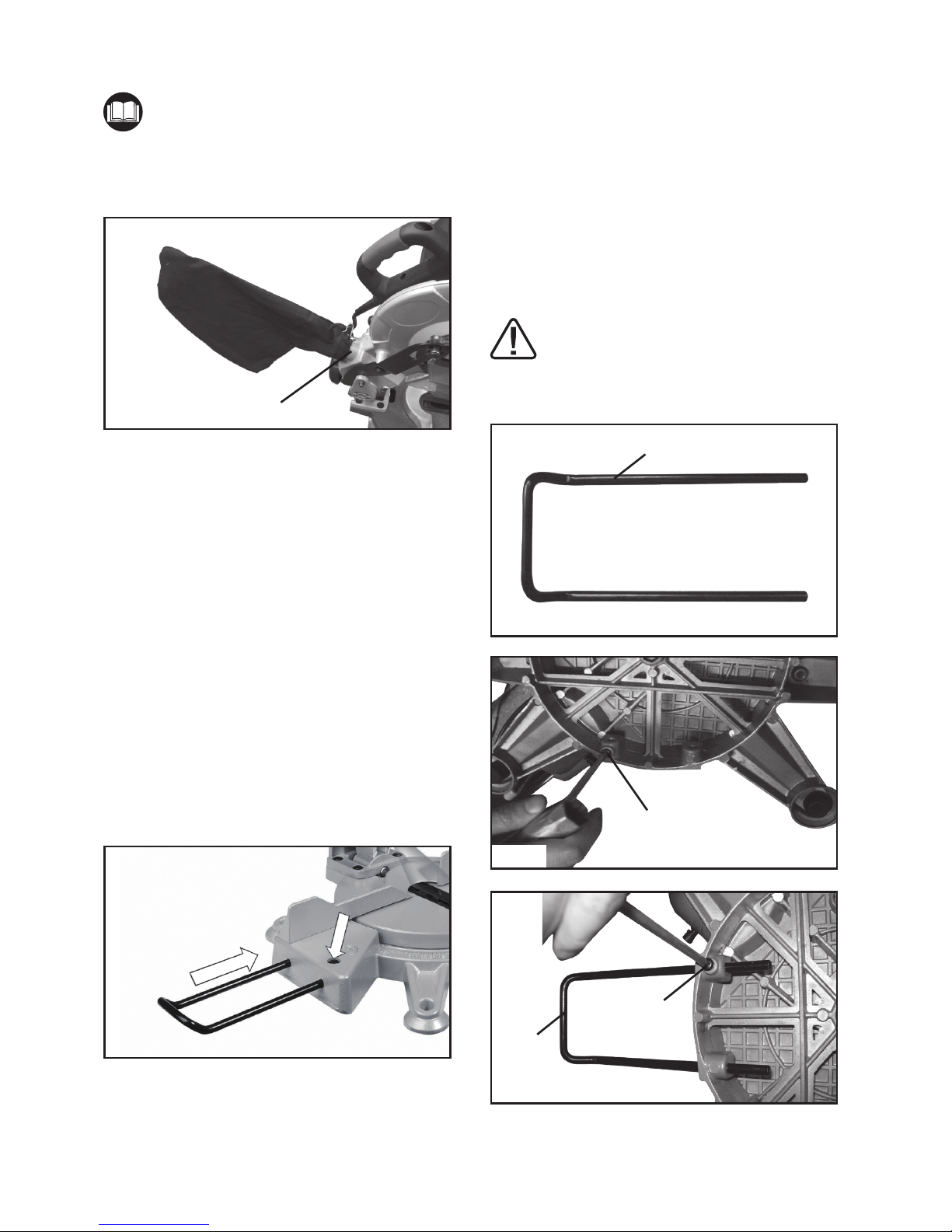
1. DUST EXTRACTION PORT (SEE A)
Fig. A
23
To reduce build up of saw dust and maintain
top efciency of cutting, the saw dust
collection can be achieved by clipping a
dust bag on the dust extraction port.
A dust bag is provided for use on your miter
saw. To install it simply t the dust bag over
the exhaust port on the upper blade guard.
To empty the dust bag, remove it from the
dust extraction port, open the dust bag by
unzipping the slide fastener.
Note:
To ensure optimal dust collecting, empty
the dust bag when it becomes lled to
approximately 2/3 of its capacity.
2. TABLE EXTENSION RAIL (SEE B)
Fig. B
To install table extension rail, simply insert
ends of extensions into the holes in either
or both sides of the base. Secure them in
place by tightening clamp screw on the
base.
The table extension rail is used for
supporting the long pieces.
3. THE SUPPORT STAND (SEE B1-B3)
Loose the screw (a) from the base. Insert
ends of support stand (26) into the holes
in the back of the base plate and tighten
the screw on the base as shown in Fig.
B1&B2&B3.
WARNING:
Always assemble the support stand
when using the product.
Fig. B1
26
Fig. B2
a
a
26
Fig. B3
Page 9

HELPLINE NO 08707252949
9
4. MOUNTING HOLES (SEE C)
Fig. C
Before use, the saw can be xed to a rm,
level surface with the 4 mounting bolts (Not
supplied).
Four mounting holes are provided in the
base of the saw to enable it to be xed to a
bench, or other supporting surface.
To mount the saw, proceed as follows:
1) Locate and mark where the saw is to be
mounted.
2) Drill 4 holes through the surface.
3) Place the sliding miter saw on the surface
aligning holes in base with holes drilled in
the surface. Install bolts, washers and hex
nuts.
5. WORK CLAMP (SEE D)
The work clamp can be tted on either side
of the saw and is fully adjustable to suit the
size of the workpiece.
Do not operate the saw without clamping
the workpiece.
Make sure that the work clamp securing
screws are tightened.
Fig. D
24
OPERATION
1. TO MAKE A CUT
1. When boxed or during storage,
transportation, the saw head is locked in the
down position. To release the head ready
for operation, apply downward pressure and
pull out the lock pin (20).
2. Connect the machine to power outlet
ensure that the mains cable is clear of the
blade and base plate.
3. Position the material to be cut on the
machine bed, ensure it is rmly held so that
it will not move during cutting.
Ensure that the rotary table locking knob
(13) and bevel lock knob (22) are tightened
before cutting.
4. Press the trigger switch and allow the
saw blade to run up the speed.
5. Still holding in the trigger switch, press
the safety release lever (16) towards the
handle. It will then be possible to push the
saw head down by the handle.
6. Continue to move the saw head down
smoothly and make the cut exerting only
gentle pressure on the downward stroke,
letting the saw do the work.
2. MITER CUTS (SEE E)
A miter cut is made at 0º bevel and any
miter angle in the range from 45º left to 45º
right.
20
13
Fig. E
Release the rotary table locking knob (13).
Move the saw to the desired angle by
twisting so that the table turns. Set at the
desired angle, and tighten the rotary table
locking knob. Make your cut.
Page 10

HELPLINE NO 08707252949
10
3. BEVEL CUTS (SEE F1, F2))
Fig. F1
22
Fig. F2
A bevel cut is made at 0º miter and any
bevel angle in the range from 0º to 45º left.
The saw can be moved from the normal 0º
perpendicular position to an angled position
down to 45º from the horizontal, on the left
only. (See F1)
To adjust head tilt, release bevel lock knob
and tilt the saw head to the left, until the
desired angle is reached on the angle scale.
Re-tighten the bevel lock knob and make
your cut. (See F2)
4. COMPOUND ANGLE CUTS (SEE G)
Fig. G
By using both the rotary table adjustment
and the head tilt, cutting of compound
angles is possible. Fig.G shows the saw
with 45º set on the rotary table and the saw
head tilted 45º.
5. LASER GUIDE (See H)
25
Fig. H
The laser guide (21) equipped with this
machine is for the purpose of precision
cutting. Make sure the batteries are tted in
the laser guide before carrying out precision
cutting. To t the batteries, remove the
battery storage cover, insert 2 x 1.5V AAA
batteries, then replace cover.
Note: Ensure correct battery polarity.
To use the laser guide, simply slide the laser
on/off switch at the “I” position, the laser
guide then projects a visible red line on the
workpiece surface, make your cut along the
red line.
Switch off the laser after cutting.
Note: The sawdust may “block” the laser
beam, clean the laser generator periodically.
Warning: Never stare directly into the
laser beam and never point the beam
at anybody.
DANGER: Laser radiation. Avoid
direct eye contact with light source.
MAINTENANCE
Warning: Remove the plug from
the socket before carrying out any
adjustment, servicing or maintenance.
When all the adjustments, settings or
maintenance have been done, make sure
that all keys and wrenches have been
removed and that all screws, bolts and
Page 11

HELPLINE NO 08707252949
11
other ttings are securely tightened.
There are no user serviceable parts in your
power tool. Never use water or chemical
cleaners to clean your power tool. Wipe
clean with a dry cloth. Always store your
power tool in a dry place. Keep the motor
ventilation slots clean. Keep all working
controls free of dust. Occasionally you may
see sparks through the ventilation slots.
This is normal and will not damage your
power tool.
If the supply cord of this power tool is
damaged, it must be replaced by a specially
prepared cord available through the service
organization.
1. PRECISION SETTING OF ANGLES
(SEE I-L)
Fig. I
a
a
Fig. J
While the machine has been factory set, it
is advisable that the 0º setting of the rotary
table and the 90º perpendicular setting
of the tilt be checked, as these positions
may have moved in transit. (Ensure
power is disconnected while making these
adjustments).
To conrm the 0º rotary table setting, set the
rotary table at 0º and tighten the rotary table
locking knob. Check that the angle between
the straight guide and the blade is 90º using
a try square (a, not supplied) as shown
in Fig.I. If the angle requires adjustment,
loosen the locking screws for straight guide
(21), and align the fence against the try
square.
Re-tighten the locking screws for straight
guide.
Similarly, check that the angle of the blade
to the face of the rotary table is 90º. If
necessary, adjust the tilt angle of the saw
head at the 90º position by loosening the set
screw (b) for 90º (See J, K)
When the 90º position is correct, tighten the
locknut (c) on the set screw for 90º.
The 45º bevel tilt should also be adjusted
use a 45º set square or miter gauge (a, not
supplied), to check the 45º angle, adjust the
set screw (d) for 45º to set the correct stop
position, then tighten the locknut (e) on the
set screw for 45º. (See K, L)
b
c
d
e
21
Fig. K
Fig. L
a
Page 12

HELPLINE NO 08707252949
12
2. CHANGING THE SAW BLADE (SEE M,
N)
Fig. M
Disconnect the saw from the power supply.
Lower the saw head until the blade securing
bolt can be seen.
Press blade spindle lock (f) and rotate
the blade until it is locked, then loosen
and remove the blade securing bolt, and
outer ange with the hex key in clockwise
direction.
Fig. N
f
Note: Blade securing bolt has a left hand
thread.
Remove the blade, (we recommend the use
of a stout glove for this). Clean any saw dust
and debris from the arbor and saw blade
securing anges.
To ret the blade, follow the above
procedure in reverse order. If you want to
take the inner ange out for cleaning, ret it
as shown in Fig.O.
Fig. O
3. REPLACING THE CARBON BRUSHES
(SEE P)
Fig. P
—Check the carbon brushes regularly. If
the carbon brushes are worn down to about
4mm, replace them with the new set (not
supplied). It must be replaced in pairs.
—With a suitable slotted screwdriver turn
the cap anti-clockwise until the carbon brush
is released, replace the brush and make
sure that they locate well and are secured
within the brush retainer.
4. MOVING THE SAW
1. When transporting the saw with xed
locations make sure that the saw head is
locked in the lower position.
2. The rotary table handle and the bevel
lock knob must all be securely tightened.
3. Use the transportation handle to lift
the saw. Do not lift the saw by the switch
handle.
Page 13

HELPLINE NO 08707252949
13
PLUG REPLACEMENT
Your Power Tool is supplied with a tted plug, however if you need to t a new plug follow
the instruction below.
IMPORTANT
The wires in the mains lead are coloured in accordance with the following code:
Blue = Neutral Brown = Live
As the colours of the wires in the mains lead of this appliance may not correspond with the
coloured markings identifying the terminals in your plug, proceed as follows:
The wire which is coloured blue must be
connected to the terminal which is marked
with N.
The wire which is coloured brown must be
connected to the terminal which is marked with
the letter L .
If a 13 AMP (BS 1363/A) Plug is used, a
13 AMP Fuse must be tted, or if any other
type of plug is used a 13 AMP Fuse must be
tted, either in the Plug or Adaptor, or on the
Distribution Board.
Note: If a moulded plug is tted and has to be
removed take great care in disposing of the
plug and severed cable, it must be destroyed to prevent engaging into a socket.
If the supply cord is damaged it must be replaced by a service agent or a similarly
qualied person in order to avoid hazard.
Environmental protection
Waste electrical products should not be disposed of with household waste. Please
recycle where facilities exist. Check with your Local Authority or retailer for recycling
advice.
If faults can not be remedied, contact the Helpline on 08707252949
GUARANTEE
This product is selected for DOMESTIC USE ONLY and not for business use.
This product is guaranteed against manufacturing defects for a period of 12 months This does not cover
the product where the fault is due to misuse, abuse, use in contravention of the instructions, or where the
product has been the subject of unauthorised modications or alterations, or has been the subject of
commercial use. In the event of a problem with the product within the guarantee period please return it to
your nearest Argos store. If the item is shown to have an inherent defect present at the time of sale, the
store will provide you with a replacement Your statutory rights remain unaffected.
Guarantor: Argos Ltd MK9 2NW
Issue 1 04/2009
Page 14

HELPLINE NO 08707252949
14
Page 15

HELPLINE NO 08707252949
15
Page 16

 Loading...