

Page 1
ASFSB
Solar
-
powered Wirefree Siren &
Strobe
The Siren is housed within a tough polycarbonate housing. This housing
provides full protection against adverse weather conditions.
A LED/Strobe unit is built into the siren to act as a visible deterrent/indication that
the system is active. The Strobe LEDs will slowly and alternately flash whether
the system is armed or disarmed. However, during an alarm condition the Strobe
LEDs will flash rapidly.
The Siren is powered by a high capacity rechargeable sealed lead acid battery.
A Solar Panel mounted on the top of the housing charges the battery during
daylight hours. During darkness, only a small amount of energy is required to
operate the Siren unit. A 9V PP3 Alkaline battery is supplied in the Siren to boost
the initial power to the unit when the system is first activated until the Solar Panel
charges the main battery.
An integral anti-tamper switch provides additional security protection to the Siren
and will immediately generate a full alarm should any unauthorized attempt be
made to interfere with and remove the siren cover.
IMPORTANT NOTE: The bell box in the kit has already been learnt to the
Gateway Hub. For replacement and additional Solar bell boxes this will need to
be learnt to the Gateway Hub. Please learn the bell box before installation.
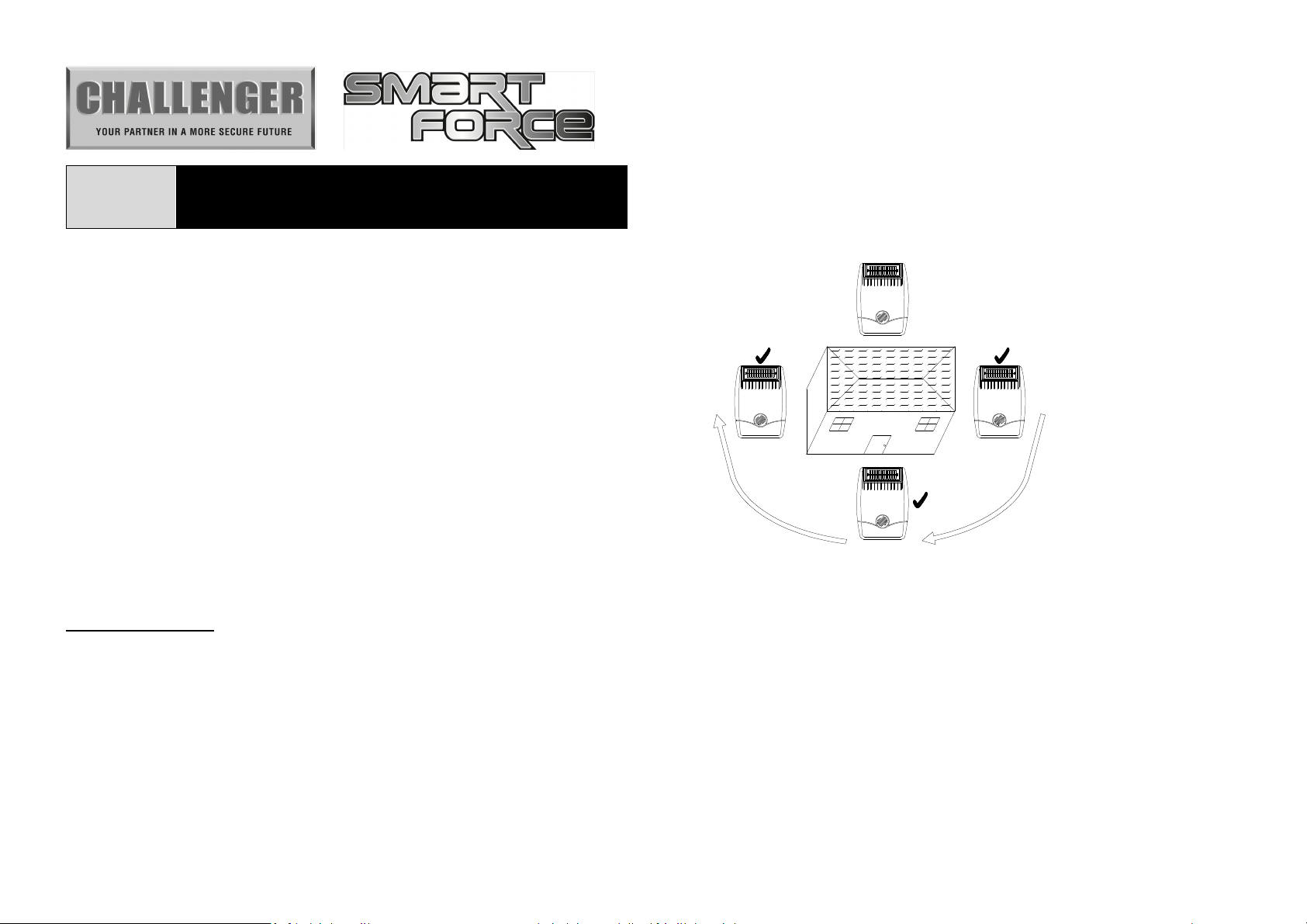
POSITIONING THE SIREN & STROBE
Please ensure the Siren is within signal range of the Gateway Hub prior to
mounting. The Siren should be located as high as possible in a prominent
position so that it can be easily seen and heard. The Siren should be mounted
on a sound flat surface so that the rear tamper switch is not activated when
mounted. Ensure that the tamper switch does not fall into the recess between
brick courses as this could prevent the switch from closing and give a permanent
tamper signal.
To provide the optimum amount of daylight to the Solar Panel, you should ideally
mount the Siren on a south facing wall. However, an easterly or westerly position
will suffice.
Although the Siren is designed to work on any aspect wall, for optimum
performance you should refrain from sitting the unit on a north facing wall where
possible.
NORTH
Avoid if
Possible
EASTWEST
SOUTH
Shadows cast by neighboring walls, trees and roof overhangs should also be
avoided. If the Siren is to be mounted below the eaves, it should be positioned a
distance of at least twice the width of the eaves overhang below the eaves.
Remembers that in winter the sun is lower in the sky and you should avoid winter
shadows where possible.
The Siren & Strobe contains sophisticated radio receiver. However, reception of
radio signals can be affected by the presence of metallic objects within the vicinity
of the Siren. It is therefore important to mount the Siren a minimum distance of
1m away from any external or internal metalwork, (i.e. drainpipes, gutters,
radiators, mirrors etc) NOT TO be fitted to metal clad walls.
Challenger_ASFSB_Instructions_Rev01
Page 2
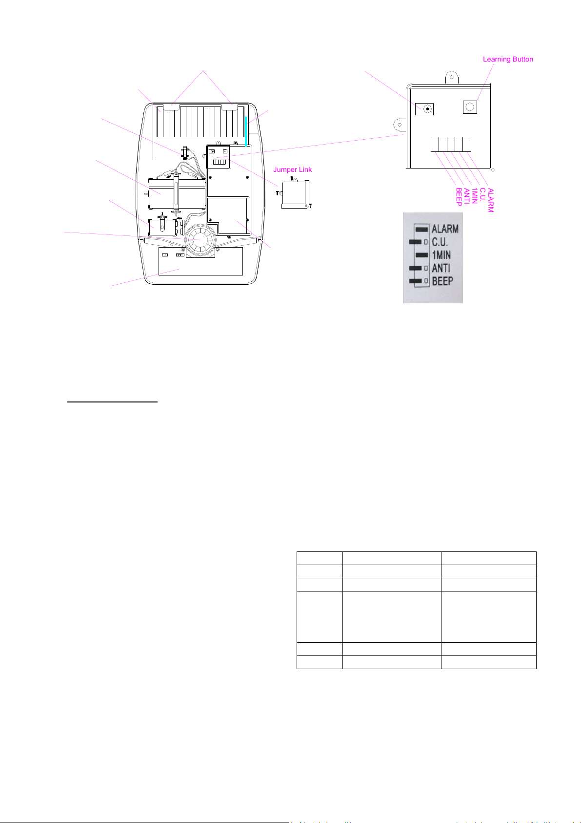
Front cover
Solar Panel
locating tabs
7.5 V DC charging
adaptor input
Learning Button
Tamper switch
6V 1.2Ahr
rechargeable
battery
SW1
DC1
JP1
9V PP3 initial
power up battery
Siren
LCD Strobe Lamp PCB
INSTALLING AND CONFIGURING
THE SIREN & STROBE
1. IMPORTANT NOTE: The siren supplied in the kit
Has already been learnt to the Gateway Hub and
does not require learning to the ASFK1 Gateway
Hub. For replacement or additional sirens these
will need to be learnt to the Gateway Hub before
use.
2. Remove the fixing screw from the bottom edge of
the Siren housing and carefully hinge off the front
cover. All electronic components are housed
within the front cover.
3. Hold the mounting plate in position and mark the
positions of the four mounting holes. A spirit
level placed on the casing will ensure a perfect
level.
4. Drill four 6mm holes and fit the wall plugs.
5. Fit the two 30mm fixing screws in the top holes
leaving approx. 10mm of the screw protruding.
6. Fit the top keyhole slots of the mounting plate
over the screw heads. Adjust the mounting
plate and adjust the screws until they form a neat
Receiver Aerial
Jumper Link
Printed circuit
board enclosure
Cover
7. Secure the mounting plate in position using the
8. Undo the 3 screws holding the jumper link Cover
9. Under the cover you will find one DC socket,
9. Jumper link JP1 is designed for function setting
Position Link fitted Link removed
ALARM Enabling alarm sound Disabling alarm sound
CU control panel based system Siren controlled system
1MIN 1 min. (control panel based
ANTI Enabling anti-jamming Disabling anti-jamming
BEEP Enabling beep sound Disabling beep sound
10. In order to prevent any unauthorized attempt to
DC1
SW1
JP1
1
B
C
A
A
M
E
E
P
L
N
.
U
A
I
T
N
.
R
I
M
Default Jumper Pin Settings
fit with the mounting plate with minimal
movement.
two 25mm fixing screws in the bottom fixing
holes.
in place and remove the cover.
jumper link JP1 and learning button SW1.
as outlined
3 min. (control panel based
system)
3 min. (siren controlled
system)
operate or disarm your system, you must
configure your system to be learnt to the
Gateway Hub.
System)
15 min. (siren controlled
System)
Challenger_ASFSB_Instructions_Rev01
Page 3

Proceed with learning the ID code as follows:
a. Please refer to Smart Force Quick Set Up
Guide. The easiest way to learn the device
is either via through the Smart Force Web
Site or Smart Force App once you have
completed the System Registration.
b. Press and hold the “learning” button for
more than 3 seconds. When the LED is
changed from illuminating steadily to
flashing, it means that the system enters
learning mode.
c. The unit has a 30-second duration to learn
the ID code.
d.
If it fails to learn the ID code within 30
seconds, three short beeps will be heard. If
successful, longer beep can be heard.
11. In the event that any of the components are out
of order, you may clear all of the preset ID
codes all at one time. Procedure is listed
hereunder:
a. Press and hold the “learning” button for
more than 3 seconds. The unit has a
30-second duration to learn the ID code.
b. Within this 30 seconds, press the “learning”
button again for more than 6 seconds.
c. After clearing all of the preset ID codes,
the LED will flash every 2 seconds and one
short beep will be emitted at 10 second
intervals.
12.
After selecting between the siren controlled
system and control panel based system by
setting jumper link JP1, be sure to disconnect
and then re-connect the power source.
After switching its mode, the preset ID code will
be no longer in existence. Resume ID code
learning process as prerequisite.
13.
Upon completion of mounting the solar panel
on the wall with the tamper switch being
pressed firmly, the siren will flash about 3
seconds as an indication of normal operation.
14. After the preset alarm duration has expired the
alarm will stop and the system will
automatically reset. Subsequent activation
will again initiate an alarm condition. If an
alarm condition is initiated more than three
times then the alarm will be locked out and any
further alarm signals will be ignored until the
system is disarmed.
15. System off is to facilitate the installation of siren
& strobe without triggering an alarm condition
despite the detector or tamper switch being
triggered. Once the installation is complete
set the system to system on.
POWER-UP OF THE SIREN &
STROBE
The use of ear defenders is advisable when working
in close proximity to the Siren due to the high sound
level produced by this device if the siren is triggered.
1. Connect the 9V PP3 initial power battery to the
battery clip.
Connect the rechargeable battery to the charging
leads. Connect the Red lead to the Red (+ve)
terminal and the Black lead to the Black (-ve)
terminals.
Note: Once the batteries have been connected,
the Siren will be operational and it is important
that the solar panel receives sufficient light to
maintain the battery charge. The Siren should
not be operated repeatedly during installation
and testing, as this will rapidly drain the battery.
It is recommended that the Siren be left for at
least a day in order to charge the battery before
the system is armed.
2. Press the anti-tamper switch, the LEDs will flash
together to indicate that the unit is operational.
3. Hinge the front cover locating tabs over the top
edge of the back plate and carefully push the
base of the siren cover into place. Secure the
siren cover in place by refitting the fixing screw
in the bottom edge of the cover. Do not over
tighten the screw as this could damage the
thread.
IMPORTANT: Ensure that the rear tamper switch
Challenger_ASFSB_Instructions_Rev01
Page 4

is closed when you fit the siren cover to the back
plate (i.e. listen for the switch to click). If the
switch does not close, this will prevent the Siren
from operating correctly. If necessary, remove
the siren cover again and adjust the screw on the
back plate tamper plunger to ensure the switch
closes when the siren is secured in position.
4. If fitted remove the protective film covering the
Solar Panel.
5. The fitting of the Siren is now complete.
OPERATING INSTRUCTIONS
1. The anti-jamming detection will be disabled,
though the jumper link JP1 of ANTI is fitted.
2. With siren being set at “system on”, when the
control panel enters the arm mode, it will transmit
radio signal to the siren which will generate one
beep. When it enters the disarm mode, the
siren will generate two short beeps. But when the
siren is system off, whenever the control panel
enters the arm or disarm mode, it will enable the
siren to be system on by emitting temperament
sound changing from low to high frequency and
during this audible transmission period the LED
will be on steadily.
3. Following activation into alarm condition, the
control panel will emit “Start” radio signal to the
siren to generate a full alarm. After alarm
condition has been disarmed manually or alarm
duration is expired, the control panel will send
“Stop” radio signal to the siren to stop the alarm
sound.
4. When the siren detects the activation of tamper
switch, it will send a radio signal to the control
panel to generate a full alarm condition.
5. When battery level drops, the siren will transmit a
radio signal to the control panel of which status
will be indicated on the control panel’s LED.
STATUS INDICATION
Status LED/Strobe Indication Audible acknowledge Explanation
No ID code LED flash every 2 seconds One short beep at 10
seconds interval
About to learn the ID
code by pressing the
learning button
LED Illuminates when
pressing the learning
button within 3 seconds.
LED flashes every 0.5
seconds by pressing the
learning button for more
After pressing the
learning button, one short
beep per second will be
emitted. Once 3
seconds is expired, one
long beep will be emitted.
Every time selecting
between siren controlled
system and control panel
based system by
disconnecting and
reconnecting the power
source or after clearing
the ID code
than 3 seconds
After that, the system
enters ID code learning
Challenger_ASFSB_Instructions_Rev01
Page 5

mode.
Under learning the ID
code
Success in learning the
ID code
LED flashes every 0.5
seconds repeatedly
LED illuminates for 0.5
seconds then
extinguishing
Failure learning the ID
code
LED flashes 3 times
rapidly
Clear the ID code LED illuminates when
pressing the learning
button. LED extinguishes
after successful clearance.
Failure ID code
clearance
LED flashes 3 times
rapidly
One short beep at 3
seconds interval
Successful learning can
be expected when both
units enter the ID code
learning mode.
Beep 0.5 seconds
3 short beep rapidly
One short beep at 0.5
seconds interval, which
lasts for 6 seconds by
emitting a long beep as
successful clearance.
Within 30 seconds
period, release and press
the learning button for
more than 6 seconds, all
of the preset ID code will
be cleared.
3 short beep rapidly Less than 6 seconds by
pressing the learning
Standby LED flashes once at 10
LED flashes once at 20
seconds interval
System off LED off Temperament sound
changing from high to low
frequency
System on LED keeps on. After
completion, LED off.
Temperament sound
changing from low to high
frequency
Delay arm mode LED flashes during 15
seconds exit/entry delay
time
The beep speed of first
10 seconds slower while
latter 5 seconds quicker
Full alarm Strobe flashes Generate full alarm
condition
button for ID code
clearance
seconds interval as low
battery indication
Enter system off
Enter system on
Enter delay arm mode
Installation is ok Strobe flashes for 3
seconds
Press the tamper switch
once resume connect the
power source or learn the
ID code after clearing the
ID code
Challenger_ASFSB_Instructions_Rev01
Page 6

Low battery indication LED flashes 20 times
rapidly
TROUBLE SHOOTINGS
Symptom Possible Cause Recommendation
LED on siren not illuminating Improper battery connection or
reverse polarity
Siren is out of order Do not attempt to open the casing
LED on siren operating, but cannot
learn the ID code or take control of
siren
Failure learning the ID code under
Siren controlled system
Radio channel interference, using
868.3MHz frequency
Ensure battery connections are
good. Connect the Red lead to the
Red (+ve) terminal and the Black
lead to the Black (-ve) terminals.
as it will invalidate the warranty.
Send it for repair.
According to the operating
instruction, resume learning the ID
code process.
Ensure it is set at siren controlled
system
Wait for a moment to start
operating
SPECIFICATIONS
Frequency 868MHz
Stand-by Current 25mA max.
Alarm Current 330mA max.
Working Range Min. 100 meter (line of sight)
Siren Volume Min. 100dB/ 1 meter
Due to our policy of continuous improvement we reserve the right to change specification without prior notice.
Errors and omissions excepted. These instructions have been carefully checked prior to publication. However, no
responsibility can be accepted by Challenger for any misinterpretation of these instructions.
Challenger Security Products
10 Sandersons Way, Blackpool, FY4 4NB
Tel: 01253 791888, Fax: 01253 791887
Email: enquiries.challenger@adivision.co.uk
Web: www.challenger.co.uk
Challenger_ASFSB_Instructions_Rev01
 Loading...