

Page 1
ASFP2
⑦
(rear cover
removed
)
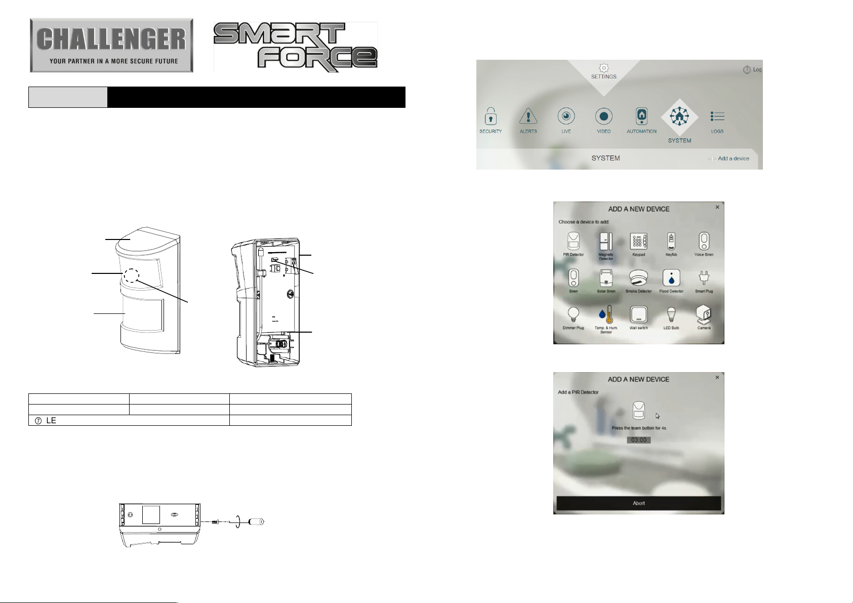
PET IMMUNE PIR MOTION DETECTOR
General Introduction
The ASFP2 PIR Motion Detector which is compatible with Smart Force Gateway hub. It detects motion
by monitoring changes in infra-red radiation levels emitted by body heat. Featuring dual PIR sensor
designed with dual lens technology, this detector is immune to presence of pets in the home allowing
your pet to move freely without causing false alarms.
Product Overview
⑦
Front Cover Upper Lens Lower Lens
Tamper switch Link button Battery Compartment
LED indicator (hidden behind lens)
Learning to Smart Force Gateway Hub
1. Undo and remove the fixing screw from the bottom of the detector. Carefully pull the bottom of the
detector away from the rear cover and then slide down to release the top clips.
2. Prepare a CR123A battery. Do not insert the battery into the unit yet.
3. Log into the Smart Force account from a web browser.
4. Select “System” then “Add a Device”.
5. Select “PIR Detector”.
6. The following screen will appear. This means the gateway is entering learning mode.
Challenger_ASFP2_Instructions_Rev01
Page 2
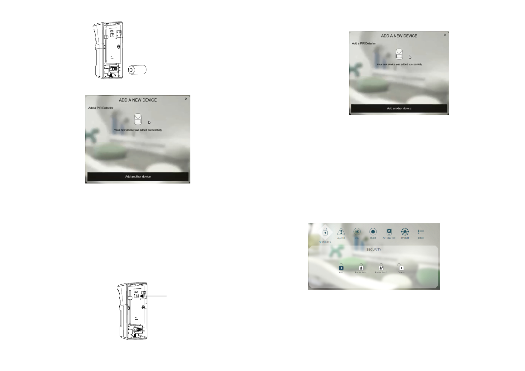
7. At this for point, insert the battery with correct polarity into the unit.
Link
button
8. The screen below will appear in 10 seconds if the process is successful.
9. Time-out will occur if the learning process was unsuccessful. Please refer to the “Manual learning”
section.
Note: Leave the detector with the rear cover open to prepare for testing.
Manual Learning
1. Repeat steps 3 to 6 of the learning process with the Smart Force Gateway section.
2. With the battery inserted, press and hold the Link button on the PCB for 3 or more seconds, and
the detector LED will start to flash, implying that it has entered ID code learning mode.
3. The LED indicator will stop flashing and turn off within 5 seconds, indicating the learning procedure
is completed. The screen below will appear indicating the process is successful.
4. If after 30 seconds the LED flashes rapidly (with an interval of 0.1 second) for 3 times, it means the
PIR failed the learing process.
Testing
Warm-Up
It will take approximately 1 minute to warm up the Detector after a battery is inserted. During this period
the LED will flash red slowly. When the LED turns red for 5 seconds, it implies warm-up procedure is
complete and the detector is ready for detection.
Testing
1. Go to System, and set it to ARM.
2. Wait for 30 secs then wave your hand in front of the detector.
3. If the test is successful the system will trigger an alarm (alarms are listed in “Events”).
Note: It is necessary that the Smart Force gateway is powered and connected to the internet.
4. If the test is unsuccessful, please check the troubleshooting section.
Challenger_ASFP2_Instructions_Rev01
Page 3

Mounting the ASFP2
Choosing a location
The detector is suitable for mounting indoor in dry interior locations only.
When considering a location for the detector the following points should be considered:
- Do not locate the detector facing a window or where it is exposed to or facing direct sunlight. PIR
detectors are not suitable for use in conservatories.
- Do not locate the detector where it is exposed to ventilation or extraction.
- Do not locate the detector directly above a heat source, (e.g. fire, radiator, boiler, etc).
- Do not locate the detector in a position where it is subject to excessive vibration.
- Internal use only.
Where possible, mount the detector in the corner of the room so that the logical path of an intruder would
cut across the detection zone. PIR detectors respond more effectively to movement across the detection
area than to movement directly towards the sensor.
More Sensitive Less Sensitive
The detector can be installed on a flat wall or in a corner as shown below.
Mount the PIR detector at height of 2m. At this height, the detector will optimize the detection range of up
to 12m with a field of view of 90°.
Flat wall mounting Corner mounting
This product comes with pet immunity mechanism so that small pets or animals will not trigger the
detector and cause false alarms. For pet immunity to be effective the pet’s height and length must not
exceed 60cm/90cm respectively to avoid triggering the detector.
Note:
If the height of your pet exceeds 60cm, you can mount the PIR detector higher to prevent the PIR from
being triggered by your pet. For example, if your pet is 70cm tall, you can mount the detector at the
height of 2.1m instead of 2m as in regular condition, and the 70cm-tall pet should be able to stroll by
without triggering the PIR. However, the same effect would also apply to human detection. So the PIR
detector should not be mounted too high to affect its regular detection purpose. You may experience the
occasional false alarm if the pet climbs or jumps on top of seating etc.
Installation
1. Remove the rear cover if it is fixed to the main body (refer to Figure 3). Use the rear cover as a
template to mark the positions of the fixing holes on the wall. Carefully drill the required mounting
holes on the wall.
Challenger_ASFP2_Instructions_Rev01
Page 4

Smart
2. Fix the rear cover to the wall using the supplied screws and wall plugs. Do not over-tighten the fixing
screws as this may distort or damage the cover.
3. Replace the main body to the rear cover and refit the fixing screw in the bottom of the PIR to secure
the main body. Do not over-tighten the fixing screw as this may damage the casing.
Operation
When the detector is mounted on the wall i.e. tamper switch is pressed for more than 10 seconds, it will
enter Normal mode.
- Upon motion being detected, the detector will send an alert signal to the controller and enter
sleep state for a preset period to conserve battery life. It will only be able to detect motion again
when this preset period is up. This preset period is called Retrigger Interval and can be set by the
controller. The default period is 3 minutes.
- Unlike in Test mode, the red indicator LED on the detector will not illuminate when triggered in
order to conserve battery life. However when the battery becomes low the LED will flash
whenever motion is detected to alert the user to replace its battery.
The detector can provide periodic auto report measurement of temperature and humidity to the
controller, or on demand when requested by the Smart Force gateway.
In the event its front cover is removed, the tamper switch will be activated and the detector will send a
Notification command to the Smart Force Gateway.
Maintenance
Low Battery: When the battery becomes low, the LED will flash red when motion is detected to indicate
low battery condition to the user. Replace the batteries as soon as possible.
Troubleshooting
The troubleshooting table lists some possible causes and solutions. Please contact your original retailer
or nearest service center if the below solutions cannot solve your problem.
Symptom Cause of Failure Recommendation
LED cannot be displayed 1. Run out of battery power.
2. Check if reverse battery
polarity.
The detector is not working 1. The PIR detector cannot
After the one-minute warm up is
completed, the detector does not
work and LED flashes on and off
repeatedly at with an interval of 2
communicate with the Smart
Force gateway.
2. Check if the detector is out of
order.
Check if detector has
completed learning with
Force Gateway
1. Replace a new battery.
2. Refit the battery with correct
polarity.
1. Place the PIR Detector closer to
the gateway.
2. Send the device in for repair and
do not open it.
Remove the battery and follow
the steps for “Manual learning”.
seconds
Reset to Factory Settings
1. Press and hold the Link button on the PCB for 3 or more seconds, and the detector LED will start
to flash.
2. Press and hold the Link button for 6 or more seconds within 30 seconds until the LED turns off.
The device is now reset back to factory mode
Specifications
Battery CR123A Lithium Battery
Operating Temperature -10°C to 40°C
PIR Warm Up Time About 1 minute
PIR Detection Coverage
PIR Pet Immunity Height≦60cm; Length≦90cm
Operating Frequency 868MHz (EU)
** Specifications are subject to change without notice.
Due to our policy of continuous improvement we reserve the right to change
specification without prior notice.
Errors and omissions excepted. These instructions have been carefully checked prior
to publication. However, no responsibility can be accepted by Challenger for any
misinterpretation of these instructions.
Challenger Security Products
10 Sandersons Way, Blackpool, FY4 4NB
Email: enquiries.challenger@adivision.co.uk
Wall-Mounted:
Up to 12m x 90° (at 2m mounting height & 25°C)
Web: www.challenger.co.uk
A50111XXXXX
Challenger_ASFP2_Instructions_Rev01
 Loading...