

Page 1
Digital Wireless Lighting Cam
SLDCRF
User s Manual
Version 0.1
01/
Apr
Page 2

2
Manual Contents:
A. Camera kit contents
3
B.
SLDCRF
overview
4
C.
Mounting the camera
15
D
. Setup
Getting started
18
E
.
Program the parameters
23
F.
Viewing images via PC and TV
30
G. Control
receiver box by remote controller
35
H. Technical Specifications
36
I.
General information and safety
37
J. FCC information
41
Page 3

3
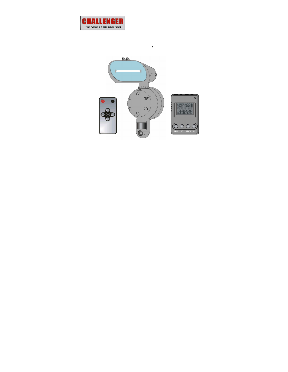
A. Camera kit contents
SLDCRF
Digital
Lighting Camera
_Camera
SLDCRF
Receiver box
SLDCRF R
emote controller
USB Cable
AV out cable
AC/DC adaptor
CDROM, Content with
SLDCRF
Webcam driver
User Manual
Page 4
4
B.
SLDCRF
overview
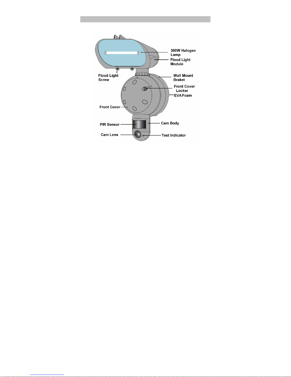
1. Front view of camera
Page 5

5
Floodlight
: It can be rotate and tilt
ing to adjust the
lighting area.
The max rotation is +/-30 Deg, tilting angle
is
10 Deg.
Flood light screw: Release to open
the flood light case
to replace the halogen lamp
Flood light cover
: Open to replace lamp
Halogen lamp: For lighting purpose, please use the
correct voltage and wattage of halogen light for this
product. Haloge
n lamp R7S, Max power: 300W.
Front cover locker
: Use to open or lock the front cover
Front cover
PIR
: Passive Infrared movement sensor.
Cam Lens
: This is the digital camera lens. Please use a
soft cloth to clear if necessary,
TEST Indicator: It is a red L
ED to indicate
the PIR
detection coverage area
.
Camera body
: It can be rotate and tilting to adjust PIR
detection area. The max rotation is +/-30 Deg, tilting
angle is 30 Deg.
Page 6
6
Wall mount bracket
: Use to mount the SLDCRF
to the
wall by provided screws
EVA
foam: Install between wall and wall mount bracket
to prevent the water leaking.
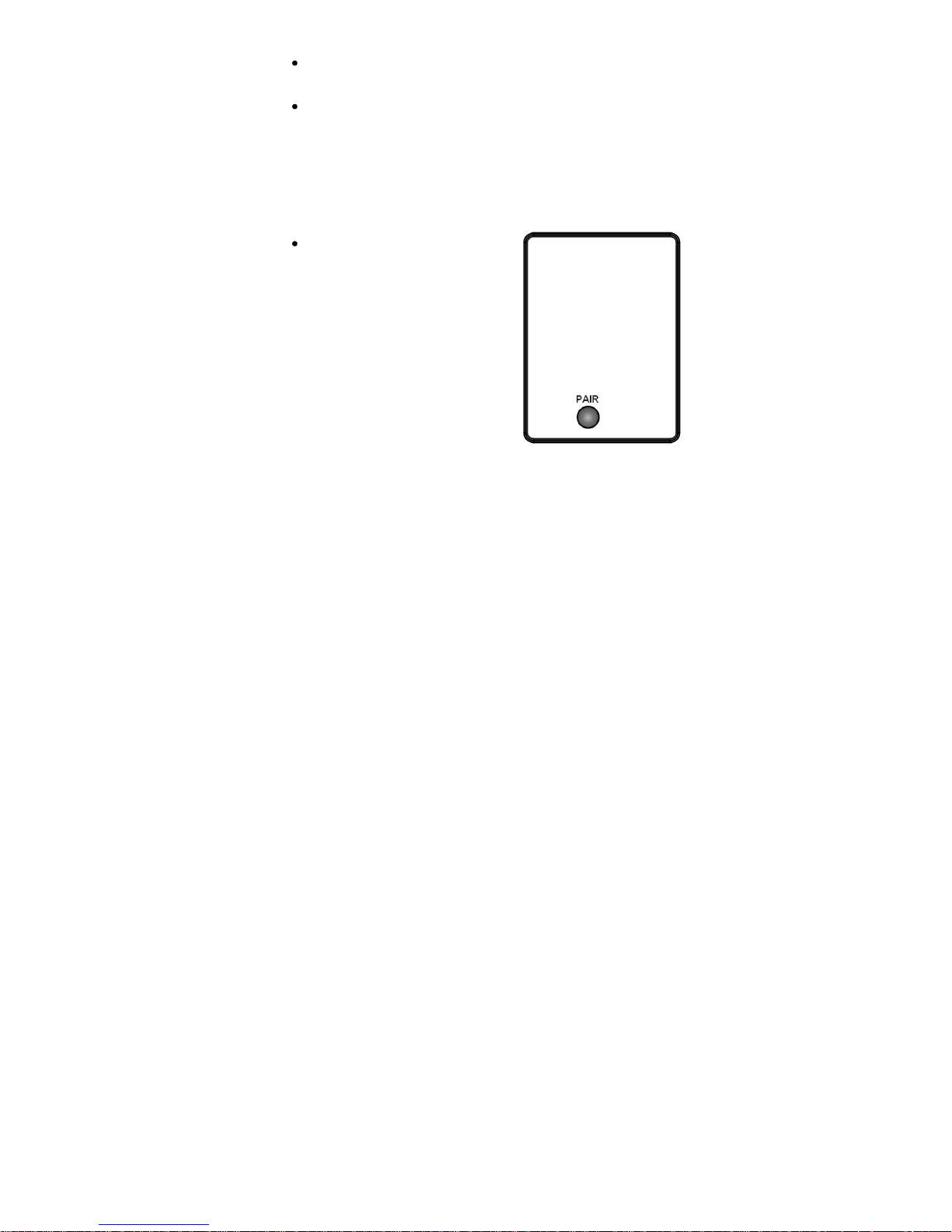
2. Control panel view
of camera
After open the front cover, you will find control panel as
below
PAIR: It uses to matching
pair with receiver box.
Page 7
7
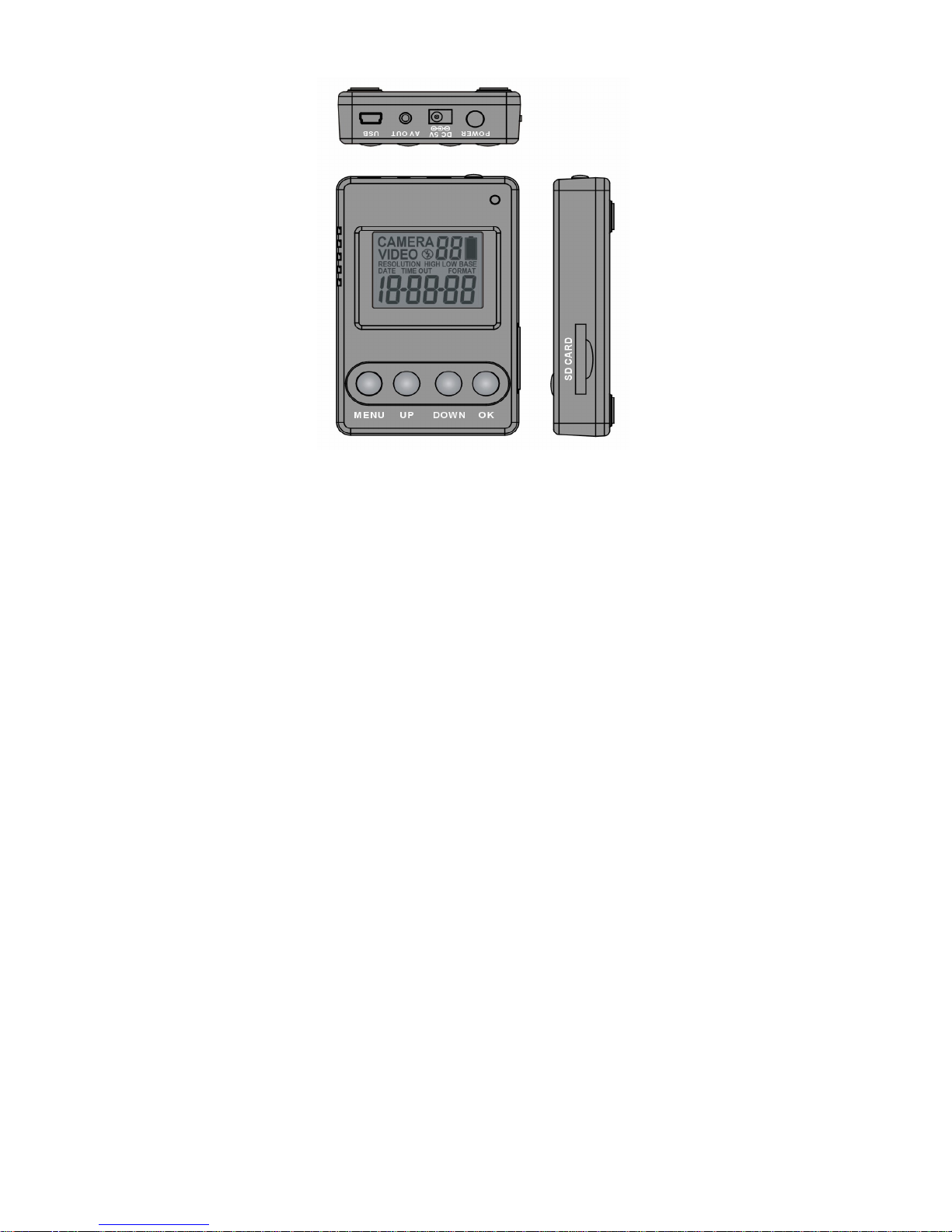
3.
V
iew
of receiver bo
x
Page 8

8
MENU Button
: Press to go t
parameter settings.
UP/DOWN button
: To program the camera parameters
as
Still image/Video/Resolutions/
Date/Time/Video
recording time/ Image and video capturing interval
time
OK button
: Press
to confirm the settings.
SD memory
card slot
: To install a SD memory card.
Ensure card is unlocked and it firmly pushed in. Press
again to release and remove.
POWER button: Press
to turn on the power of Receiver
box while it is power off.
DC 5V socket
: Power source connector, connecting
to
provided AC/DC adaptor
AV OUT
socket
: Video and Audio signal output port,
connecting to provided AV cable to TV
USB
socket
: To connect the USB cable from
SLDCRF
to PC to access the captured image/video.
Infrared receiver
: To receive the
remote
control
signal
from REMOTE controller.
Page 9
9
Operation indicator
: Shows the operation status of
Camera and
Receiver box.
Blinking
: Ind
icating data is transmitting from
camera to
receiver box.
Light up
: Indicating the SLDCRF
is
operating.
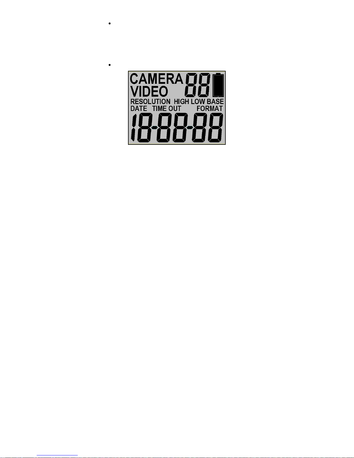
LCD display
CAMERA
: Still
image cap
ture icon. Indicates your
SLDCRF
will capture a single image.
Page 10

10
VIDEO
: Video-captur
ing icon. Indicating your SLDCRF
is
in video capturing mode and recording time will depend
on the video recording time setting.
18-88-88
: Image
/video
counter to sh
ow how many images
or videos have been captured.
And at parameter settings,
it shows the Date and Time setting.
RESOLUTION HIGH: Indicates the
SLDCRF
is in high
-
resolution still image capturing or video capturing.
RESOLUTION LOW: Indicates the
SLDCRF
is in
Low
-
resolution still image capturing or video capturing.
D
ATE: Indicates the
SLDCRF
is in Date setting
.
TIME: Indicates the
SLDCRF
is in Time setting.
TIME OUT: Indicates the SLDCRF
is in Time interval
setting.
FORMAT: Indicates the
SLDCRF
is in SD card
Format
setting.
Page 11

11
4.
V
iew
of Remote controller
Page 12

12
POWER button
: Press once
to turn on the p
ower of
Receiver box while
power
is
off. Pressing and hold it 2
seconds to turn off the power of Receiver box while it is
power on.
It is same function of POWER button
on the receiver box.
AV button
: When receiver box is connected to TV by
provided AV cable, pressing and hold AV button 2
seconds to switch the receiver box to AV OUT mode
from receiving mode.
SET button
: Pressing and hold 2 seconds to switch the
receiv
er box back to receiving mode
MENU Button
: Press to go
to parameter settings.
UP/DOWN button
: To program the camera parameters
as Still image/Video/Resolutions/Date/Time/Video
recording time/ Image and video capturing interval
time
OK button
: Pressing to
confirm the settings.
Infrared
transmitter
: To transmit remote control data
from remote controller to receiver box.
Page 13

13
5. Picture / Image Capacity
SD card
High 1.3M
1280 x 800
Low VGA
640 x 480
Base CIF
384 x 240
AVI
VGA
10 seconds
1G
2500
5000
10000
200
2G
5
000
10000
20000
400
4G
10000
20000
40000
800
NOTE
: Picture / Image Capacity Chart shows the approximate
number of images or video clips that can be stored based on
the resolution setting and the size of memory card. These
figures may vary d
epending on the amou
nt of detail in the
image.
Memory Options
Up to 4GB SD card
Your
SLDCRF wireless lig
hting camera
is equipped with 32
MB
bui
lt in SDRAM memory. Please note that the
built in memory is
only for storage buffer and
data
processing buffer
only, the
captured image or video cannot store on internal memory,
please install the memory card to memory card slot of receiver
box. The memory card slot capable of accepting up to 4
GB SD
card (sold separately). With no memory card inserted into the
Page 14

14
slo
t,
the display will show
Err
to indicate non memory card
installed. Also, i
t is not recommended that a card is inserted or
removed during operation as this can cause malfunction.
Page 15

15
C
. Mounting the camera
Mount the
SLDCRF to a solid surfac
e more than ½ or 12.7mm
thick in a secure location overseeing the area to monitor
. We
suggest you mount the camera between 2 meters off the
ground with the camera pointing at a downward angle 15
degrees. Be sure to avoid mounting the camera facing east or
west as the rising and setting of the sun may produce false
triggers and overexposed images.
Ensure the
front of your
SLDCRF
is
clear of any
branches
and other
debris so
your camera
view or PIR
sensor are
not
obscured.
Page 16

16
1. Connect the
SLDCRF
to AC power.
Please make sure your
SLDCRF
is rated for your
voltage before connection. Incorrect voltage will
damage the camera.
BLUE WIRE FOR NEUTRAL
YELLOW / GREEN WIRE FOR EARTH
BROWN WIRE FOR LIVE
IMPORTANT
Observe correct wiring as
failure to do so will damage
unit and void warranty
We recommend using a supply that you can switch off if
required. Once wired correctly, turn on the mains supply.
When connected, if the
environmental
brig
htness is not
enough, the SLDCRF
lamp will turn o
n for approximately
60 seconds.
This
60 seconds to inform user leave the
capturing area, then it is ready for operation and will
begin recording images each time the motion sensor is
triggered.
Page 17

17
2. Replacing the
halogen lamp.
CAUTION
SLDCRF
lamp will be very
hot.
Always disconnect the power to your
SLDCRF
before
opening.
Release the floodlight screw to open the floodlight cover.
Carefully remove the Halogen lamp
it may be HOT.
Insert a new Halogen lamp making sure you do not
touch the lamp with bare skin.
Halogen Lamp : Max
300W R7S
Close the floodlight cover and screw together carefully.
Page 18

18
D
. S
etup
getting started
1. Connecting the power to receiver box
Place the receiver box at a de
sk or somewhere easy to
access and easy for remote controller to acc
ess.
Plug the provided AC adaptor to wall AC outlet as below
Plug the small plug to receiver box DC 5V as below.
Please make sure the output voltage of AC outlet is
correct
to match
the operation AC voltage of AC
adaptor.
The operation voltage of AC adap
tor is 100
~ 240 volts.
Page 19

19
2. Inserting SD card
receiver box
SD cards must not contain any other images and
you must ensure your
SLDCRF receiver box is
power off
when adding
or removing an SD memory
card, and make sure the SD card is unlock.
Failure to
o
bserve these rules may result in malfunction.
Inserting the SD memory card into the SD card slot
completely and in the correct direction as shown on the
inside of the housing.
DO NOT FORCE THE SD CARD
To remove the SD memory card by
push
ing
the SD card
in, and it will spring out, now pull out the card gently.
Page 20

20
3. Matching pair of Camera with Receiver box
After mount
ing
the
SLDCRF
Camera to wall properly.
Using the hex screw driver to release the screw from
front cover, then
turn front cover anti-clockwis
e and then
take front cover off
.
A PAIR button will be found on the control panel.
Press
the POWER button of receiver box to turn on the
receiver power.
Press
UP, DOWN
and
OK button
at the same time once
within 30 seconds
of power up
.
The display of receiv
er box will show
P10
and start
count
ing
down.
Press
the PAIR button of camera once.
The display of receiver box will stop count
ing
down and
after 3 seconds, the operation indicator will turn on.
SLDCRF
Camera is
now
matched pair with receiver box.
Page 21

21
4. Te
sting the
capturing area
PIR coverage area
The testing is to make sure that the capturing and PIR
coverage area is correct
.
After completing
above matching pair steps
, connect
the
provided
AV cable to AV OUT of
receiver box and
AV IN
of TV
as below
Cha
nging the TV to play the AV
The TV will show live footage
of camera.
Ad
just the position of your SLDCRF
if necessary, until
the desired
coverage area is
achieved.
Page 22

22
When you have completed the coverage area testing,
ple
ase disconnect
the AV cable from
recei
ver box and
TV, or press
the
SET
button
from the
remote control unit
to switch recei
ver box back to capturing mode.
Page 23

23
E. Program the parameters
1. Default
Settings.
You can change the parameters
on your SLDCRF
from receiver
box. The d
efault values
are shown below.
Setting
Default
Time
12
:00
HH:MM
Date
01:01:10
MM:DD:YY
Image
capture interval
1 minute
01-59
Resolution
High
High/Low
/Base
Burst
2P
1 - 3P
I
mage capture method
Photo
Video/Photo
Floodlight control
Auto
Auto
Video recording time
10 seconds 05 - 60
Your
SLDCRF
can be used straight away but before use you
may wish to change some or all of the settings
see the next
sections.
Page 24

24
2. Set
the R
esolution
After power on the receiver box, press the SET button
then MENU button within 30 seconds to enter
programming.
If MENU button is not pressed within 30 seconds,
camera will automatically enter PIR detection mode.
The first program setting is resolution.
After pressed the
MENU
button
The word RESOLUTION will be blinking on the display.
Press OK button to choose the selection.
Press the UP or DOWN
button to
select the desired
resolution
HIGH
/
LOW or BASE
And then
press
OK
to save and exit to CAPTURING
setting.
3. Set
the capturing
sequence
Set the Still Image
Mode
. Your
SLDCRF
can be
programmed
to shoot 1~3
pictures per triggering.
Page 25

25
After exit the resolution setting, the
word CAMERA will
be blinking
on the display
Press OK button to choose the selection.
Then
the numbe
r of burst mode will
now blink.
Press the
UP or DOWN
button to select the
desired burst mode
setting (1P to 3P
of pictures per triggering).
The number of burst mode is 1P to 3P.
Press OK to save
your selection and exit to TIME OUT
settings.
Set the Video Mode: Your
SLDCRF
can program to
recor
d 5~60
seconds of video per triggering.
After p
ressing the
MENU button, p
ress UP button twice
to enter video setting mode. The word VIDEO will be
blinking
on the display
Press
the OK
button and the video length in seconds will
be blinki
ng.
Press
the UP or D
OWN
button to select the desired
video length (from 5 seconds to
60 seconds in 5 second
increment
s).
Page 26

26
Press
the OK button to save and exit to TIME OUT
setting.
4. Set the Time out
The word TIME OUT will be blinking on the display
Press
th
e OK button and the time out time will now blink.
Press
the UP
or DOWN
button to increase or decrease
the
interval
time value in minutes from 01 to 59 minutes.
Pr
ess
the OK to save your selection
and exit to Date &
Time setting.
5.
Set the Date and Time: This SLDCRF
uses the 24hr
military time format.
The word TIME will be blinking
on the display.
Press
the OK button
to enter minute setting first.
Minute
digit will be blinking. Press UP
or
DOWN
to
increase or decrease the minute value (0
59)
Press OK
to c
onfirm the minute setting and enter hours
setting.
Hour
digit will be blinking. Press UP or DOWN
to
increase or decrease the hour value (00
23)
Page 27

27
Press OK
to confirm the hour setting and enter year
setting.
Year
digit will be blinking. Press UP or DOWN to
increase or decrease the year value.
Once this is done, press OK
and enter month setting.
Month
digit will be blinking. Press UP or DOWN
to
increase or decrease the
month
value. (01
12)
Press OK
to confirm the month setting and enter date
setting.
Da
te
digit will be blinking. Press UP
or D
OWN
to
increase or decrease the date value. (1 31)
Once this is done, press
OK to save
. You ll see the word
-
dEL - blinking. Now press [MENU] to exit program
setting and
go
back to status screen.
NOTE: Sett
ings and images stored on internal
memory may be lost in the event of a power failure.
Alw
ays ensure you reset your SLDCRF
following a
loss of power.
Page 28

28
6. Deleting im
ages
without viewing screen
After p
ressing the M
ENU
button,
press DWON
button
once to ente
r t
he delete mode. The word - dEL -is
blinking.
Press
the
OK button to enter the DELETE & FORMAT
menu.
Using the UP and DOWN
buttons to select the desired
function. NO-dl (No Delete), (d
-ONE) Delete one, (d-ALL)
Delete ALL,
or FORMAT.
Pressing the OK
to
confirm your selection.
If you choose to delete one picture at a time, (d-ONE), it
will delete the last picture from the memory
card,
Press
MENU button to return the capturing mode, and
you will find
the
image/video counter
decreased one.
If you choose t
o delete all images (d-ALL), it will delete
all images.
Press
MENU button to return the capturing mode, and
Page 29

29
you will find the image counter is return to 00000
If you choose to format your memory, it will erase all
images. This feature is particularly us
eful if you dont
want to look through the images one at a time.
To exit the delete setting
, press UP
or DN button to
select NO-
dl (
No Delete
) then
press [MENU] to back to
capturing mode
.
Page 30

30
F
. Viewing images via PC
and
TV
You can connect directly
to the
receiver box
of your
SLDCRF
using the provided USB cable to PC
.
Alternatively you can use a card reader or a digital
camera to read the SD card.
When connected the SD card will show as a removable
hard drive an
d you can use Windows Explorer to
see
y
our
SLDCRF
captured images or video. Y
ou can copy
the images t
o your PC or delete them from
you
r PC
directly.
Page 31

31
1.
Viewing images via your receiver box directly on your
PC
Connect
the provided USB cable to your PC
Press
and hold the MENU button then plug the USB
cable to USB socket of your receiver box, then release
the MENU button
The receiver box of
our SLDCRF
will automatically
change to USB mode and the display will show USb
.
Your PC will setup automatically.
The
SD
memory
card will now show on your co
mputer
as a removable drive.
Click
the removable drive to open the file, an VIDEO file
will be found under root directory
This VIDEO file contains all the captured images/videos
by folder, and folder name is the date of created, and the
image name is the
captured time and sequence.
Now you can view all the captured image or video from
your PC.
Page 32

32
2.
Viewing the image via your recevier box diectly on your
TV
Connect
the provided AV cable to AV OUT of receiver
box and AV IN of TV as below
Change the TV to view the AV
Channel
Press
the MENU button once to switch the receiver box
to TV out mode.
The captured image/video files will be shown on the TV.
Press
the UP or DOWN button to play the captured
image or video.
Page 33

33
3. Viewing
a live image from
SLDCRF
Your
SLDCRF can also be used as a web cam
Please install the
SLDCRF
Webcam driver to your PC
first.
Install the provided CDROM to your PC, and then c
lick
SETUP. EXE
to install the driver.
Connect
the provided USB cable to your PC and other
side to USB socket of your SLDCRF
receiver box
.
The receiver box of your SLDCRF will automatically
change to web cam mode and the display will show
PC
C
Your PC will setup the installed driver automatically.
Now you can use Windows application software to view
a live image.
Viewin
g a live image from
SLDCRF
is only available
for Win 2000, Win XP and Win Vista.
Note:
If you are using a long USB
cable
or your
computer s USB port is unable to provide enough
power for the
SLDCRF
you may experience
difficulties such as no operation, bl
ack and white or
Page 34

34
poor picture quality. Please try a different USB port
or shorter cable.
Page 35

35
G. Control the receiver box by remote controller
The Remote controller is a full operation i
nfrared
transmitter; you can use it to access the receiver
box
within 7 metre
and +/- 12 deg.
All the buttons function
s and
operation are
same as the
button of receiver box, please
refer to
Program the
parameter
section and
view
of the remote controller
section to access the receiver
box, and play the captured
im
age/video
.
The remote controller uses a
button cell battery, please
follow the figure on the back
side of remote controller to
replace the battery when
battery is low.
Page 36

36
H
. Technical Specifications
1. System Requirements and Compatibility
Windows 2000/Me/XP
/Vista
/Win 7.
Live viewing is not support with Win 7.
Pentium 1G
MHz or equivalent processor.
256
MB SDRAM or above.
VGA Video Card with 32MB RAM minimum
Colour 32
bit or higher.
Sound Card.
An available CDROM driver and an available USB Port.
20G
B free har
d disc space.
If you have any questions regarding your PC
specifications please refer to your PC manufacturer.
Page 37

37
2. Features and specification
PIR detection angle 52 Deg and detection range up to
9M.
Low Lux colour CMOS Image Sensor 1.3
M pixels.
Max Reso
lution
: 1.3
M pixels,
1280 x 800
pixels.
2
Capture options: Still image
1P to 3P burst capturing,
and
video recording
Image performance for video stream:
20
fps at 640 x 480
pixels
Built in 32
MB SDRAM for image
buffer
Built in status LCD display
on the r
eceiver box
Built in SD card slot for SD memory card
on the receiver
box and support up to 4GB.
Automatic exposure control, white balance and
sharpness
Auto Date & Time stamp
on the captured image/video
file and file name
High precision 4 piece glass lens
with IR coating
Focusing: 1.5m (minimum) to Infinity
Page 38

38
Effective viewing angle: 48 deg
Built in USB plug for PC access
Interface type: USB 1.1
Image format: JPG, Motion JPEG
Powered by AC 230V
.
Floodlight tube is 300W, type R7S
Auto light sensor.
Infrared
remote controller with full control buttons
Product measurements: H300
x
W170 x T85
mm. Weight
1.2Kg, SLDCRF
Camera only.
Operating Environment: 14 to 104 deg F (-10 to 40 deg
C). 20-85% relative humidity, non-condensation.
Page 39

39
I.
General Information and
safety
Storing conditions
Storage conditions: -20ºC to 55ºC, 20-85% R.H., non
-
condensing
Spec
ial care instructions.
The
SLDCRF
is designed only to be weather resistant.
Never attempt to immerse the unit in water or any other
liquid. This will damage the un
it and void the warranty.
Use a soft lens cloth for cleaning lens. Avoid touching
lens with fingers.
Remove dirt or stains with a soft cloth dampened with
water or mild detergent. Keep the
SLDCRF
in a dry and
cool dust-free environment or container when it
is NOT
used.
Do not open the SLDCRF
for unauthoris
ed service. This
could cause serious damage to the unit and will void
your warranty.
This
SLDCRF
is a precision electronic device. Do not
attempt to service this camera yourself, as opening or
removing
covers may expose you to dangerous voltage
Page 40

40
points or other risks.
Do not touch the floodlight when the power is on, it is
extremely hot.
Page 41

41
J
. FCC Information
This device complies with Part 15 of the FCC Rules. Operation is
subject to the follo
wing two conditions: (1) This device may not
cause harmful interference, and (2) This device must accept any
interference received, including interference that may cause
undesired operation.
Warning: Changes or modification to this unit not expressly
appro
ved by the party responsible for compliance could void the
user s authority to operate the equipment.
NOTE: This equipment has been tested and found to comply
with the limited for Class B digital device, pursuant to Part 15 of
the FCC Rules. Their
limits a
re designed to provide reasonable
protection against harmful interference in a residential installation.
This equipment generates, uses and can radiate radio frequency
energy and, if not installed and used in accordance with the
Page 42

42
instructions, may cause ha
rmful interference to radio
communications.
However, there is no guarantee that interference will not occur in
a particular installation. If the equipment does cause harmful
interference to radio or television reception, which can be
determined by turning
the equipment off and on, the user is
encouraged to try to correct the interference by one or more of
the following measures:
Reorient or relocate the receiving antenna.
Increase the separation between the equipment and receiver.
Connect the equipment int
o an outlet on a circuit different from
that to which the receiver is connected.
Consult the dealer or an experienced radio/TV technician for
help.
SLDCRF
_R0
.1.
Page 43

43
Page 44

44
Challenger Security Products
4 Arkwright Court
Fylde Industrial Estate
Blackpool
Lancashire
FY4 5DR
Tel: 01253 791888
Fax: 01253 791887
Email: sales.challenger@adivision.co.uk
Web: www.challenger.co.uk
 Loading...