

Page 1
SL180N SL180BN Instructions Rev02
MODEL: SL180N / SL180BN
INSTALLATION AND OPERATING INSTRUCTIONS
FOR STAND-ALONE PIR DETECTOR
We are delighted that you have purchased this PIR detector. This detector is constructed and tested to IP44 and is suitable for
outdoor use. Please read the instruction manual before installation and retain for future reference.
IMPORTANT: Never modify the sensor as there are no user serviceable parts inside. Not suitable for use with dimmer switches.
Install in accordance with I.E.C. Wiring Regulations(Rigid Cable 0.75~1.50mm2. The SL180N/SL180BN SHOULD BE INSTALLED BY
A QUALIFIED ELECTRICIAN.
Please pay attention to the following:
Before commencing any electrical work, ensure the mains supply is isolated by switching off and removing the relevant fuse.
POSITIONING THE UNIT
When selecting the mounting position, take the following points into account:
1.
The sensor is designed for optimum performance when mounted 2.5 meters above ground level.
2.
Avoid positioning close to trees or shrubs which may cause false triggering during wet, windy weather.
3.
Avoid pointing at or positioning close to heat sources such as flues or heat extraction units, which may cause false triggering.
4.
Avoid pointing at bright lights as unit will not function when you set Lux control level to dark
( position)
5.
Avoid mounting close to strong electromagnetic fields, which may cause false triggering.
6.
The sensor is most sensitive to movement across the detection area as opposed to directly towards or away from the unit.
Position the unit to point across flow areas.
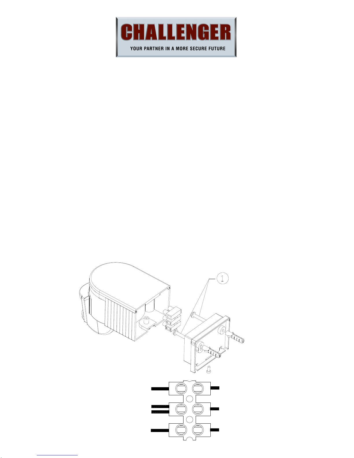
FITTING THE UNIT (Referring to the above figure)
Before commencing any electrical work, ensure mains supply cables are isolated by switching off and removing the relevant
Black(PIR Wire)
Black(Lamp Wire)
Blue(Lamp Wire)
Blue(Power Cable)
Brown (Power Cable)
Brown(PIR Wire)
Blue(PIR Wire)
L
N
LS
Page 2
SL180N SL180BN Instructions Rev02
fuse.
1. Unscrew the sensor backplate screw, remove the main body cover and terminal block
2. Affix the sensor backplate to the mounting surface with raw plugs and screws.
3. Connecting the main power wires and “load” wires to the terminal block (see the relative symbols), the wires must pass
through a rubber gasket (supplied in plastic bag). Refit the terminal block to the sensor backplate using the location lugs.
4. Attach the main body sensor the backplate retighten the screw
After finishing the fitting operation, you can adjust the detection area and working state of PIR sensor.
WALK TESTING:
When power is switched on to the SL180N/SL180BN, the SL180N/SL180BN detector will enter into a “WARM-UP” period for
approximately 30 seconds (within 1 minute) and then automatically change into “AUTO MODE”. Whilst in the AUTO MODE, you
can then carry out a Walk-Test by placing the LUX control to day position () and the TIME control to minimum (-). Once the
SL180N/SL180BN sensor receives a valid trigger signal (such as movement of a human body or heat) within its detection area, the
lamp(s) (load) will be turned on for the pre-set period of time. You will be able to determine the detection area by walking slowly
across the front of the sensor.
After completing the walk-test, set the LUX KNOB to the night position to ensure SL180N/SL180BN only operates at night and
set TIME KNOB to the desired “ON’ time.
ADJUSTING THE LUX CONTROL LEVEL:
The Lux control module has a built-in sensing device (photocell) that detects daylight and darkness.
() position denotes that the lamp(s) (load) will be turned on by PIR during day and night.
() position denotes that the lamp(s) (load) will be turned on by PIR only at night.
You can set to operate the unit at the desired level by adjusting the LUX knob
ADJUSTING THE DURATION TIME:
The duration time is “the length of time that the SL180N/SL180BN switches the load ‘on’ after activation”. The duration time
can be adjusted from approx 10 seconds to 10±2 minutes. Rotating the TIME knob from (+) to (-) will reduce the duration time.
Note: Once the lamp(s) (load) has been triggered by the PIR sensor any subsequent detection will start the timed period again
from the beginning.
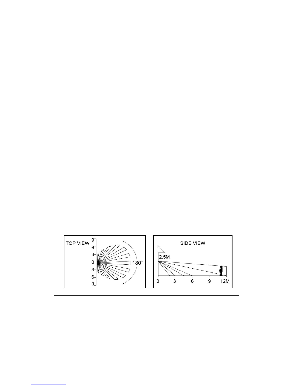
Detection area drawing
Page 3

SL180N SL180BN Instructions Rev02
How to change into MANUAL CONTRL MODE
1. When power on, the PIR detector enters into the “WARM-UP” periods for about 1 minute, then automatically change into
AUTO MODE.
2. At daytime, during AUTO MODE, if LUX setting at night level, by switching the main switch OFF/ON for 2 times within 3
seconds, the PIR detector will not turn on the light immediately but it will automatically change into 4hours MANUAL MODE
from AUTO MODE in the evening. At night, during AUTO MODE, by switching the main switch OFF/ON for 2 times within 3
seconds, the PIR detector will automatically change into 4hours MANUAL MODE from AUTO MODE. In MANUAL MODE, the
Lamp(s) will remain ON, not affected by duration time and Lux control level, after 4hours or when dawn comes, the lamp will
change into AUTO MODE again.
3. During MANUAL MODE or AUTO MODE, by switching off the ON/OFF main switch over 10 seconds and then on again, the PIR
detector will reset to WARN-UP periods. Please note: the periods of “WARM-UP” maybe be shorter than 1 minute.
TECHNICAL DETAILS
VOLTAGE: 220-240 VAC 50 Hz
LOAD: Max.1000W incandescent or Max.300W fluorescent
DETECTION ANGLE: Approximately 180°(horizontal) and 60°(vertical)
DETECTION DISTANCE: Max. 12 meters
DURATION TIME: 10 seconds up to 10±2 minutes adjustable
LUX CONTROL LEVEL: From daylight to night adjustable
WATERPROOF: IP44
Due to our policy of continuous improvement we reserve the right to change specification without prior notice.
Errors and omissions excepted.
These instructions have been carefully checked prior to publication. However, no responsibility can be accepted by Challenger Security
Products for any misinterpretation of these instructions.
3
P O W E R O N A U T O M O D E
4 H O U R S M A N U A L
M O D E ,T H E N A U T O
M O D E
1
2
CHALLENGER SECURITY PRODUCTS
10 Sandersons Way,
Blackpool, FY4 4NB
Tel :01253 791 888 Fax:01253 791 887
Email: enquiries.challenger@adivision.co.uk
Website: www.challenger.co.uk
 Loading...