

Page 1
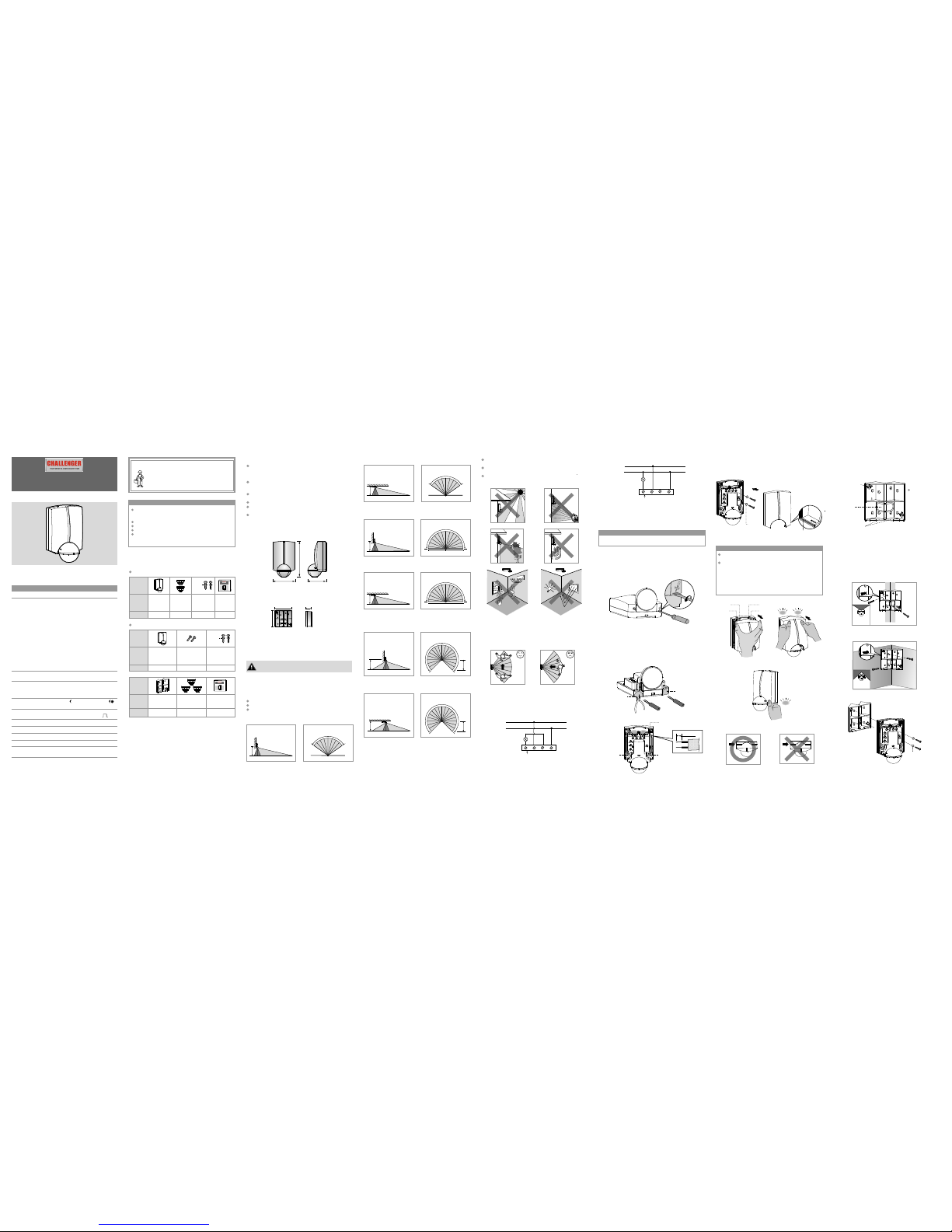
FIG.9- B
Click
22
22
FIG.1- B
2 PROD UCT D ESC RIPTION
FIG.4
3.2.1 Typ e 1:
Please d isconn ect powe r comple tely and r ead the
entire i nstruc tion man ual care fully be fore ins tallat ion.
Item
Item
Item
Quanti ty
Quanti ty
Quanti ty
Patter n
Patter n
Patter n
SL01, SL 01B / SL02 , SL02B
SL03, SL 03B
Manual
1
1
1
INSTRUCTION MA NUAL
Lens
shield s
Detect or
Detect or
Wood screws
x
Φ4 25.4MM
+ Rubber
washers
Wood screws
x
Φ4 25.4MM
+ Rubber
washers
3
Manual
1
Lens
shield s
3.1.1
the
inner co verage i s a circul ar with ra dius of 0. 5M.
O
SL01, SL 01B dete ction an gle: 110 (See FIG.2 -A).
O
SL02, SL 02B dete ction an gle: 180 (See FIG. 2-B).
O
SL03, SL 03B dete ction an gle: 270 (See FIG. 2-C).
It is reco mmende d to insta ll the det ector at t he heigh t
of 2 - 3M. The d etecti on range c an reach u p to 10M,
3.3.1 Wa ll mount
3.3.1. 1 Unscre w the fron t cover by s crewdr iver.
3.3.1. 2 To insert th e "-" head s crewdr iver bla de into th e gap
betwee n front co ver and bo ttom cas e, then ro tate
anti-c lockwi se 90° to det ach the fr ont cove r
(See FIG .6).
3.3 In stall ation p roce dure
SL01, SL 02, SL03 c an be inst alled on t he wall di rectly,
recess / c orner wi th wall br acket, ( SL03, SL 03B only ) or on
the ceil ing dire ctly.
NOTE
NOTE
SL01 /SL 01B/ SL02 /
SL02 B/S L03/ SL03 B
230V~5 0Hz
N
L
Load
L N N L
FIG.5
3.2.2 Typ e 2:
230V~5 0Hz
N
L
Load
L N N L
Φ3.5 x 10MM
Screws
Rubber
washer
FIG.11- A
FIG.11- B
Rubber
washer
x x
Detect or : 129 80 63MM ( See FIG. 1-A)
2.2 Di mensi on
1 PACKAGE CONTENTS
3 INSTALLATION A ND WI RING
3.1 Se lect a pr oper l ocati on
3.2 Wi ring ( See FIG .5)
Motion d etecto r is facto ry defau lt for
wall mou nt.
SL01, SL 02, SL03 ,
FIG.1- A
129
80
63
DO NOT rem ove the ru bber str ip and mak e sure it li nes
up with th e front co ver perf ectly (S ee FIG.8 ).
There sh ould be a cl ick soun d, this id entifi es that th e
upper ho ok has bee n fasten ed into th e slot (Se e FIG.9- A),
and a seco nd click s ound sho ws the low er hook ha s been
fasten ed into th e slot ( See F IG.9-B ). Pleas e ensure f ront
cover is l ocked we ll on bott om case (S ee FIG.9 -C),
IMPORTA NT NOTE - If no t (See FIG .9-D), w ater wil l
enter in to the ins ide of pro duct and w ill caus e damage t o
the unit a nd there i s potent ial of ele ctrica l shock.
FIG.6
3.3.2. 2 Break sc rew knoc k-outs ( See FIG. 10), the n fix the
wall bra cket ont o recess / c orner wi th wood sc rews
(See FIG .11-A & FIG. 11-B), ma ke sure "U P"mark
upward s. refer t o 3.3.1. 1 - 3.3.1. 3 to conne ct power
cables , and fix th e bottom c ase on wal l bracke t
(See FIG .12), th en assem bly fron t cover.
FIG.10
FIG.3
W
3.3.1. 3 Cut the ca ble entr y knock- out by a pli ers or cut ters
(See FIG .7-A), a nd feed ca bles thr ough cab le entry
knock- out and ru bber gas ket, the n refer to w iring
diagra m (See FIG .5) to con nect pow er cable s, and
please b e noted to s trip off 6 - 8 MM of cabl e
sheath ing (See F IG.7-B ).
FIG.9- A
FIG.8
Rubber
washer
Rubber s trip
Front co ver
inside v iew
Click
Click
Slot
Slot
Hook
Hook
Wall mou nt
Top view
o
110
10M 10M
R0.5M0
Side vie w
FIG.7- A
Rated Vol tage 230 V~50Hz
Load SL01 , SL01B / S L02, SL 02B:
Max. 5A (co sφ=1)
Incand escent L amp: Max . 1000W
HV Halog en Lamp: M ax. 500W
LED Lamp : Max. 120 W
Energy S aving: 2 00VA(in clude
CFL and PL La mp)
SL03, S L03B:
Max. 8A (co sφ=1)
Incand escent L amp: Max . 1840W
HV Halog en Lamp: M ax. 1000 W
LV Haloge n Lamp: Ma x. 300VA
Fluore scent La mp: Max. 4 00VA
(Uncom pensat ed)
LED Lamp : Max. 150 W
Energy S aving: 2 00VA(in clude
CFL and PL La mp)
Detect ion angl e
O
SL01, S L01B: u p to 110
O
SL02, S L02B: u p to 180
O
SL03, S L03B: u p to 270
LUX
Adjust ment
Auto OFF
Time Del ay
from " - " (ap prox.6 sec) to
" + "
" Test ",
(appro x.10mi n) and" "
LED Mode O FF / Warni ng / Watch
Meter Max. 10MAdjust ment
Power Co nsumpt ion Appr ox. 1W
Instal lation h eight
2.0 - 3.0M , recomm ended
instal lation h eight is a pprox. 2 .5M
o o
Operat ing Temper ature -2 0 C to +45 C
Enviro nmenta l IP44
Protec tion
1S.
TECH NICAL S PECI FICATI ONS
From" " (a pprox. 5 LUX) to " "
( )
∞
SL01, SL 01B, SL0 2, SL02B , SL03, SL 03B are pa ssive in fra
red sens ors to swi tch vari ous type s of load up on detec tion
of movem ent. Sui table fo r indoor o r outdoo r use and us ed
in resid ential o r commer cial env ironme nts.
0.5M 0 0.5M 10M
2.5M
FIG.2- A (SL01, SL 01B)
Ceili ng mount
Top view
o
110
10M 10M
R0.5M0
Side vie w
0.5M 0 0.5M 10M
2.5M
As the det ector re sponds t o temper ature ch ange, pl ease
avoid th e follow ing cond itions ( see FIG. 3):
3.1.2 He lpful ti ps for ins tallat ion.
Avoid di rectin g the tow ard the ob jects wh ose
surfac es are hig hly refl ective , such as mi rror, mon itor, etc .
detect or
Avoid mo unting t he detec tor near h eat sour ces, suc h as
heatin g vents, a ir condi tioner s, vents , l ights, e tc.
Avoid ai ming the d etecto r toward s object s which ma y
move in th e wind, su ch as curt ains, ta ll plant s, trees e tc.
o
180
10M 10M
0 R0.5M
FIG.2- C ( )SL03, S L03B
Wall mou nt
Ceili ng mount
Top view
FIG.2- B (SL02, S L02B)
Wall mou nt
Top view
10M 10M
O
270
R0.5M
7M
Top view
10M 10M
O
270
R0.5M
7M
Side vie w
Ceili ng mount
Side vie w
o
180
10M 10M
0 R0.5M
Top view
Side vie w
Side vie w
0.5M 0 0.5M 10M
2.5M
0.5M 0 0.5M 10M
2.5M
7M 0.5M 0 0.5M 10M
2.5M
7M 0.5M 0 0.5M 10M
2.5M
3.3.2 Co rner / rec ess moun t with wal l bracke t.
wall bra cket is de signed f or vario us
applic ation ( Se e FIG.10 ), break t he knock -out to
feed the w ires thr ough the c orresp onding h ole.
3.3.2. 1 8-knoc k-out
FIG.9- DFIG.9- C
Cable en try
knock- out
Cable en try
knock- out
Verify ca refull y and make s ure the wi res are co nnecte d
correc tly.
3.1.3 Pa y attent ion when t esting , the dete ction ar ea is more
sensit ive cros s the dete ctor up to 1 0 , and t owards t he
detect or acros s up to 1m (Se e FIG.4) .
m
Less sens itive to mov ement
directl y towards de tector
More sens itive to mov ement
across th e pattern
CAUTI ON!
A circuit b reaker ( 250VAC, 1 0A) type C a ccordi ng to
EN6089 8-1 of loa dⅠshall be i nstall ed in the fi xed wiri ng
for prot ection .
Do not mou nt on cond uctive s urface .
Do not ope n the encl osure fr equent ly.
Turn off po wer when r eplaci ng lamps .
High in- rush cur rent wou ld occur w hen lamp s of certa in
brands u sed whic h may dama ge the uni t perman ently.
Various t ypes of li ghting l oad can be c onnect ed to suit
most app licati ons.
Lens shi eld equi pped for e asy deta chment a nd fixin g
enable s a precis e adjust ing of the d etecti on zone.
MOTI ON DET ECTO R LIGH T CONT ROL
SL01/SL01B/SL02/
SL02B/SL03/SL03B
MOTION DETECTOR LIGHT CONTROL
SL01/SL01B/SL02/
SL02B/SL03/SL03B
MOTION DETECTOR LIGHT CONTROL
1
Corner
mounti ng
bracke t
Wall corner mounting bracket (Optional purchase):80 74.528mm
(See FIG.1-B)
x x
74.5mm
80mm
28mm
Screw su pport
Cable en try
knock- out
Cable en try
knock- out
1
2
3
5
4
6
7
8
1-8 hole s are
screw
knock- outs
Corner installation
Recess installation
U
P
U
P
UP
UP
3.3.1. 4 Put wood s crews in to the rub ber wash er,and fi x
the bott om case on t he wall or c eiling ,
up the fro nt cover a nd tight en it with s crews.
(See FIG .8).
then cov er
FIG.7- B
L'
L
N
N
6-8MM
Earth te rminal
Rubber
gasket
Rubber
gasket
METER
TIME
Test
1S.
LUX
LED Mode
Warning
OFFWatch
2.1 Fea ture s
4 Progra mmable d isplay L ED's sho w the dete ctor sta te.
Choose d iffere nt confi gurati ons to sho w detect or is in
standb y or test mo de. They c an also be t urned of f if not
requir ed.
Can be wal l or ceili ng mount ed. SL03 & S L03B can a lso
be corne r (inter nal & exte rnal) mo unted wi th the sup plied
corner b racket .
Unique d esign fo r multi- direct ion sens ing incl uding up /
down / for ward / sid eways ad justme nt.
3 versio ns avail able wit h differ ent dete ction an gles.
Instal lation m ust be car ried out b y qualif ied
electr icians o r skille d/comp etent pe rson who i s
famili ar with th e approp riate st andard s and
techni cal requ iremen ts of the ap plianc e and its
proper i nstall ation.
Contac t a qualif ied elec tricia n in the eve nt of
fault or b reak dow n.
FIG.12
Rubber
washer
Page 2
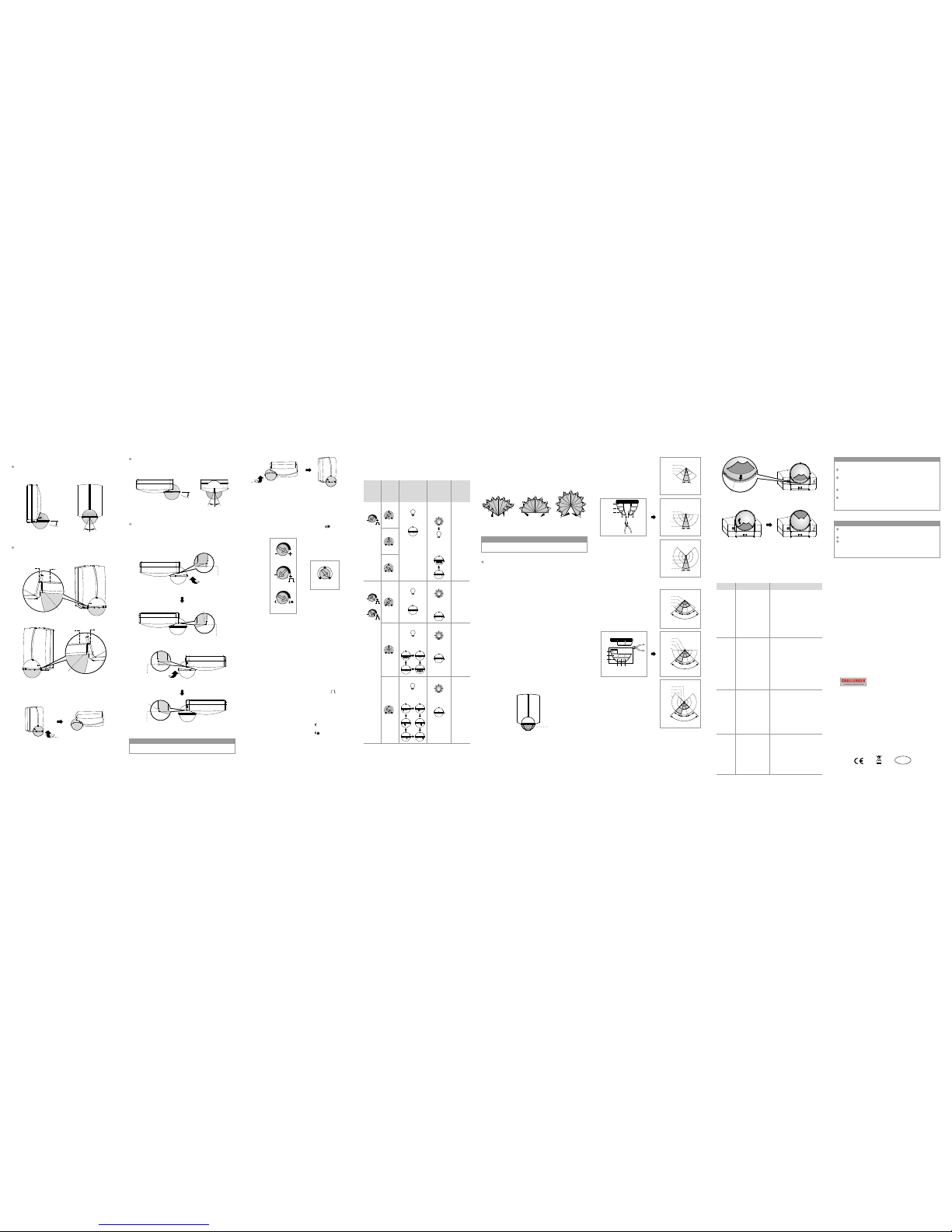
4.1 Ad juste r sett ings
4.2 Wal k test
FIG.17
4.1.1 ME TER sett ings
4.1.1. 1
4.1.1. 2
4.1.1. 3
Set METE R knob val ue at the po sition o f " - " for the
" smalle st field o f view ".
Set METE R knob val ue at the po sition o f " + " for the
" larges t field of v iew ".
Set METE R knob val ue at the po sition b etween " - "
and " + " for " de sired fi eld of vie w ".
4.1.4 LE D mode set ting
LED mode c an be swit ched to "w atch", " warnin g" or "off " in
normal u se. Plea se note LE D's act di fferen tly in "Test " mode.
See belo w for LED op tions.
FIG.18
3.28. 02184 018101 01
Load OFF.
LEDs OFF.
Load ON
2sec, th en
OFF.
LEDs ON
2sec, th en
OFF.
Test
mode
TIME
settin g
LED
mode
settin g
Standb y,
Load and
LED stat us
Impuls e,
Load and
LED stat us
Whethe r
Impuls e
is controlle d
by LUX
NO
LED Mode
Warning
OFF Watch
Warning
OFF
Watch
Warning
OFF
Watch
Warning
OFF
Watch
METER
LUX
TIME
Test
1S.
Test
1S.
4.3.2 Cu t the exce ss lens sh ield by a sc issors o r cutter s.
4.3.3 Fi x lens shi eld: Pus h the lens s hield in to the slo t path
( See FIG. 22), the n along th e slot pat h to turn ri ght or
left ( See F IG.23) .
Walk Test
SL01, SL 01B
SL02, SL 02B SL03, SL 03B
Start
Finish
Start
Finish
Start
Finish
4.1.3 LU X settin gs
4.1.3. 1 When set ting the L UX knob to " ", the det ector wi ll
operat e the ligh ting onl y in the dar kness.
4.1.3. 2 When set ting the L UX knob to " ", the det ector wi ll
operat e the ligh ting at an y light le vel.
4.1.3. 3 To adjust th e LUX knob a ccordi ng to user 's neede d.
W
W
W
All LEDs f lash
simult aneously.
LED flas hes
in turn.
LEDs all
OFF.
Load ON.
No test
mode
YES
YES
YES
Warning
OFF
Watch
Warning
OFF
Watch
Warning
OFF
Watch
Test
1S.
Test
1S.
LEDs all
OFF.
LEDs all O FF.
LEDs all
OFF.
Load OFF.
W
Load OFF.
W
Load OFF.
W
W
Load ON.
W
Load ON.
W
2sec
2sec
FIG.15 -D
FIG.15 -C
Detect or base ed ge
Detect or
base
edge
Grove in d etecto r head
Groove i n
detect or head
4 OPERATION AND FUNCTION
4.1.2 TI ME setti ngs
4.1.2. 1 Set TIME k nob valu e at the pos ition of " Tes t ", start
to walk te st , the loa d and LED tu rn on 2sec t hen turn
off whil e detect or is trig gered.
4.1.2. 2 Set TIME k nob valu e at the pos ition of " - " , the
minimu m delay ti me will be 6 sec.
4.1.2. 3 Set TIME k nob valu e at the pos ition of " + " , the
maximu m delay ti me will be 1 0min.
4.1.2. 4 Set TIME k nob valu e at the pos ition of " " ,
for "sho rt impul se" mode . Used if de tector c onnect ed
to a seper ate time s witch. T he time sw itch wil l receiv e
1sec sig nal once S L01, SL0 2, SL03 is t rigger ed, then
the ligh t ON 1sec, O FF 9sec.
4.1.2. 5 To adjust th e TIME kno b in betwe en" - " &" + "
accord ing to use r's desi re.
5 TROUBLE S HOOTING
If the det ector is n ot funct ioning c orrect ly, pleas e check th e
follow ing tabl e for assi stance :
Problem
Lighti ng
device
does
not turn
on
Nuisan ce
trigge ring
Lighti ng
device
does not
turn off
LED
does not
turn on
Possib le cause
1. Exceed ing the
detect ion
range.
2. No power
suppli ed.
3.TIME k nob is
not loca ted to
TEST pos ition.
4. Wired
incorr ectly.
1. time
se tting .
2.D is
nuisa nce
trigg ered.
3. Wired
incorr ectly.
Incor rect
etecto r
There ar e heat
source s, highl y
reflec tive obj ects
or any obj ects
which ma y be
swayed i n the
wind wit hin the
detect ion
covera ge.
1. Power d oes
not turn o n.
2. Wired
incorr ectly.
3. LUX Kno b
adjust ed
incorr ectly.
4. Malfu nction ed
load.
Sugges ted solu tion
1. Walk in t he effect ive
detect ion rang e
2. Switc h on the pow er.
3. TIME kn ob must be
locate d to TEST po sition .
4. Refer t o wiring d iagram s.
1. To test the d elay tim e
specif ied on TIM E knob
and chec k is
nuisan ce trigg ered if li ght ing devi ce does no t turn
off as the d elay tim e is up.
2. Keep aw ay from de tectio n
covera ge to avoi d activa t ing wh ile doin g
the test .
3. Make su re load an d wires
are conn ected co rrectl y.
detect or
detect or
Avoid ai ming the
toward a ny heat so urces,
such as ai r condit ioners ,
electr ic fans, h eaters o r any
highly r eflect ive surf aces.
Make sur e there ar e no
swayin g object s within t he
detect ion cove rage.
detect or
1. Switc h on the pow er.
2. Refer t o wiring d iagram s
( FIG.5) a nd check i f the
load is ma lfunct ioned.
3. Check i f LUX knob a re set
to the cor rect pos ition.
4. Repla ce the dis abled lo ad
with a new o ne.
T
adjust er
he purpo se of the wa lk test is t o select a p roper in stalla tion
place an d gain the d esired d etecti on cover age. Turn M ETER
to " + ", TIME k nob to " Test ", t hen cond ucting a w alk
test ref erring t o step 4.1 ( See FIG. 18).
NOTE
The foll owing co nditio ns may cau se lower s enseti vity:
In very fo ggy cond itions , the sens itivi ty may be re duced
due to moi sure col lating o n the lens .
In very ho t condit ions, th e sensit ivity ma y be reduc es as
high amb ient tem peratu re could b e close to b ody
temper ature.
In cold co nditio ns when he avy clot hing is us ed, very l ittle
heat is em itted fr om the bod y (espec ially if f ace is cov ered)
Cleani ng: Wipe w ith dry cl oth only. S oap or rou gh cloth
may dama ge the det ector le ns.
NOTE
It takes a pprox. 6 0sec to wa rm up afte r power is s upplie d.
NOTE
adjust er
adjust er
Be aware o f the walk d irecti on (See FI G.4).
4.2.1 Sw itch pow er on.
4.2.2 Us er must be w ithin th e detect ion cove rage.
4.2.3 Aft er the war ming up pe riod, wa lk from ou tside
across t o the dete ction pa ttern un til LED tu rns on for
approx . 2sec .
4.2.4 Ro tate sen sor head t o change t he detec tion dir ection
(See FIG .13-A, FIG.13 -B & FIG.1 5-A,FI G.15-B ).
4.2.5 Adj ust METE R to chan ge detec tion ran ge.
4.2.6 Adj ust TIME t o change t he delay t ime for li ght.
4.2.7 Re fer to sec tion " 4.3 " t o use the le ns mask fo r
reduci ng the det ection z one.
4.2.8 Re peat ste p 4.2.5 - 4. 2.6 unti l meets us er's dem ands
4.2.9
4.3 Us age of l ens sh ield
The defa ult sett ing of eac h knob bef ore ex-f actory i s as
follow ing: MET ER: " + ", TIM E: " Test " , LUX: , L ED mode:
" Watch " (S ee FIG.1 7).
1S.
4.3.1S L01, SL0 2 has two pi eces of le ns shiel ds, and SL 03
has thre e pieces o f lens shi eld. Len s shield c onsist s of
three la yers , eac h layer is d ivided i nto 3 smal l units,
O
and the un it can mas k an angle o f approx . 30 , wh en
mounti ng the det ector at t he heigh t of 2.5M, t he outer
covera ge is:
Layer C el iminat ed: mask t he zone wi th a secto r
about fr om 0.5M to 4 .5M. Lay er B elimi nated: m ask the
zone wit h a sector a bout fro m 0.5M to 7M . Layer A
elimin ated: ma sk the zon e with a sec tor abou t from
0.5M to1 0M.
The inne r covera ge is a circ ular wit h radius o f 0.5M
Separ ate lens s hield ca n be elimi nated
to fit use r's desi red dete ction ar ea (See FI G.19 &
FIG.20 & F IG.21) .
(See FIG .21),
To rotate an ti- cloc kwise 18 0 of det ector he ad for wal l
mount ( Se e FIG.16 ).
O
FIG.16
FIG.15 -A
25O25
O
28
O
FIG.15 -B
FIG.15 -E
Groove i n
detect or head
For opti mum dete ction ra nge, ens ure that t he end of th e
groove s on the det ector he ad (see FI G 15-C & FIG 1 5-E)
match up w ith the de tector b ase edge ( see FIG 15 -D &
FIG 15-F ).
Groove i n detect or head
FIG.15 -F
O
Detect or head ca n be adjus ted down ward max . 28
vertic ally (Se e FIG.15 -A) to sho rten the d etecti on range ,
O
or turne d leftwa rd and rig htward m ax. 25 h orizon tally
(See FIG .15-B) .
The sele cted par t
to be elim inated
FIG.21
A
B
C
a b c
Take examp le: cut th e lens
shield w ith plie r.
FIG.22
FIG.23
Slot pat h
b(30
o
)
a(
3
0
o
)
c
(
3
0
o
)
R10 m
R7 m
R0.5 m
R4.5 m
90
o
Detect ion patte rn
FIG.13 -C
3.3.2. 3 Desire d detect ion angl e can be rea ched by de tector
head adj ustmen ts after w all moun t finish ed.
O
Detect or head ca n be adjus ted down ward max .15
vertic ally (Se e FIG.13 -A) to sho rten the d etecti on range ,
O
or turne d leftwa rd and rig htward m ax. 25 h orizon tally
(See FIG .13-B) .
FIG.13 -B
FIG.13 -D
Line A
Bulge
Line C
In order t o obtain o ptimum d etecti on range , it must be
carefu l to ensur e that lef tward Li ne B (See FI G.13-C ) and
rightw ard Line C ( See FIG. 13-D) al ign bulg e respec tively
to keep de tector h ead hori zontal ly.
3.3.3C eiling m ount
3.3.3. 2 Fix it ont o the ceil ing refe r to step 3. 3.1.1 - 3. 3.1.4.
3.3.3. 3 Desire d detect ion angl e can be rea ched by de tector
head adj ustmen ts after c eiling m ount fin ished.
FIG.14
3.3.3. 1To rotate c lockwi se 180 o f detect or head fo r ceilin g
mount (S ee FIG.1 4).
O
FIG.13 -A
25O25
O
15
O
Line A
Line B
Bulge
FIG.19
SL01, SL 01B
Detect ion patte rn
A
ABB
C
C
a
A
B
C
b
c
Take examp le: cut a le ns
shield w ith plie r.
30
o
R0.5 m
R4.5 m
R10 m
R7 m
R0.5 m
R7 m
R4.5 m
Detect ion patte rn
30
o
R10 m
SL02, SL 02B
30
o
A
A
B
B
C
R10 m
R7 m
R0.5 m
R4.5 m
b(30
o
)
90
o
a
(30
o
)
c
(
30
o
)
Detect ion patte rn
A
B
C
b(30
o
)
a(3
0
o
)
c(3
0
o
)
R10 m
R7 m
R0.5 m
R4.5 m
90
o
Detect ion patte rn
AB
C
C
R10 m
R0.5 m
R7 m
R4.5 m
SL03, SL 03B
Detect ion patte rn
FIG.20
Test proc edure
O
180
O
180
Rotate sl ightly
Rotate sl ightly
CHALLE NGER SEC URITY PR ODUCTS
SANDER SONS WAY
MARTON
BLACKP OOL
FY4 4NB
Tel No: 0125 3 792898
Websit e: www.ch alleng er.co.u k
Email: e nquiri es.cha llenge r@adiv ision. co.uk
RoHS
Conform
CAUTI ON!
Due to our p olicy of c ontinu ous impr ovemen t we reser ve
the righ t to chang e specif icatio n withou t prior no tice.
Errors a nd omiss ions exc epted.
These in struct ions hav e been car efully c hecked p rior to
public ation. H owever, n o respon sibili ty can be ac cepted
by Chall enger fo r any misi nterpr etatio n of these
instru ctions .
SL01, SL 01B
SL02, SL 02B
SL03, SL 03B
 Loading...