

Page 1

The Challenge Machinery Company provides owner's manuals on its
products s olely as a court esy to i ts cust omers. Se e the inf ormati on belo w
before using this manual.
These manuals are for reference only. These manuals include products which are noncurrent,
unsupported or no longer pr oduced by The Chal l enge M achi nery Com pany , and are pr ov ided sol el y as
an accommodat i on to our c ustom ers. By prov i ding these m anuals, T he Ch al lenge M achi nery Com pany
makes no representation or warranty as to the products, their current condition, or their suitability or
fitness for use in any particular application, which are the sole and i ndependent responsibility of the
product owner and user.
Older produ cts may not co mply with curren t safety pro cedures, guidel ines or regu lat ions, and i t
is the product owner's and user's responsibility to evaluate the suitability and fitness of the
products in their current use and application. The Challenge Machinery Company makes no
representation, warranty or recommendation regarding any modifications which may be
required on non -current o r u nsuppo rted prod ucts. T he Ch allenge Mach inery Co mpan y assumes
no liability for any modification or alteration to any Challenge product, and any such
modification or alteration to any Challenge product is not authorized by The Challenge
Machinery Comp any. The av ailabilit y of t hese manuals is sol el y for t he purpose of provi ding ref erence
information for the products.
This manual may not be complete in all aspects of product maintenance and repair. All products
should be used only by qualified and properly trained personnel, following proper safety
procedures. Al l product s should be regular l y i nspected and m aintai ned, and their condition, appli cation
and use should be periodically evaluated by qualified personnel. Only qualified and properly trained
technicians should perform maintenance, repair and replacement procedures. Attempting these
procedures without pr oper training may cause machine dam age or operat or injury!
Products may be unsup por ted by The Chall enge M ac hinery Company due to age or the unavailability of
parts from their ori ginal m anufactur er. No parts or produc t support will be available to repair or maintain
unsupported prod uc ts. Older products may not be UL listed (if the product does not have a UL l abel it i s
not a listed product), and may not comply with applicable installation or other regulations or
requirement s if rel ocated to a new f acilit y. Many munici palities requi re a product t o be UL l isted bef ore
an electrician will connect power to them. Often the cost of updating an older pro duct to compl y with
current saf ety r egulations is greater than the v alue of t he product .
The Challeng e Machin ery Comp any
6125 Norton Center Drive
Norton Shores, MI 49441-6081 USA
ChallengeMachinery.com
F.265XT-EO
TITAN 265 XT
Operator’s Manual
Serial Numbers 071755 & Up
Sold and Serviced by
January 2014
Page 2

1.0 Introduction
1.0 Introductio n
THIS MANUAL is designed to help you get the most from your Challenge equi pment. Keep this
manual in a safe, conv enient place for quick reference by operators and service personnel.
SAFETY ALERT! This symbol means CAUTION: P erson al saf et y
instructions! Pay special attention to the instructions in bol d ty pe. Personal injury may result if the
precautions are not r ead and followed.
READ THIS MANUAL BEFORE OPERATING! Follow precautions and instr uc tions given and you
should have years of trouble-free operation. If after reading the manual questions sti ll remain, contact
your Authorized Challenge Dealer.
FOR PARTS AND SERVICE contact the Authorized Challenge Deal er fr om whom you pur c hased
your machine. Use the illustrations and parts lists at the bac k of this manual to identify the correct
parts needed. Always give the SERIAL NUMBER and MODEL of your machine to insure t he correct
parts are sent as soon as possible.
Take a few minutes right now to RECO RD YOUR MACHINE S E RIAL NUMBER in the space
provided on the front cover of this manual. Also be sure to fill out the warranty card accompanying
your machine and r eturn it DIRE CTLY TO CHALLENG E.
If you bought a used machine, it is important to have the following information on record at Chall enge.
Copy this page, fill in the information and send it care of The Challenge Serv ice Department, Norton
Center Drive • Norton S hor es • MI 49441-6081.
CHALLENGE MODEL SERIAL NUMBER
ATTN COMPANY
ADDRESS
CITY STATE/PROVINCE ZIP
PHONE DATE INSTALLED
DEALER NAME & CITY
* WARRANTY INFORMATION *
It is very important that y ou r ead and under st and the conditions outli ned in the Warr anty Information
Sheet att ached to the outside of the shipping cont ainer of your machine.
The Warr anty Inf or m ation Sheet must be filled out completely and returned to THE CHALLENGE
MACHINERY COMPANY in order for the warranty to be issued for this machine.
Challenge® is a registered trademark of The Challenge Machinery Company• 6125 Norton Center Drive • Norton Shores, MI
49441-6081
Copyright© 2007-2013 by The Challenge Machinery Company. All rights reserved. Printed in the U.S.A
2
Page 3

1.0 Introduction
TABLE OF CONTENTS
1.0 Introduc tion................................................................................................................................. 2
2.0 Safety .........................................................................................................................................5
2.1 Precautions............................................................................................................................. 5
2.2 Power Lockout Proc edur e .......................................................................................................5
2.3 Warning Label Definitions........................................................................................................6
3.0 Packing List.................................................................................................................................8
Optional Items .............................................................................................................................. 8
4.0 Specifications.............................................................................................................................. 9
5.0 Installation & Setup ...................................................................................................................10
5.1 Inspecting Shipment.............................................................................................................. 10
5.2 Uncrating.............................................................................................................................. 10
5.3 Cleaning ............................................................................................................................... 11
5.4 Fitti ng Through Nar r ow Door .................................................................................................11
5.4.1 Removing the Extension Tables ..................................................................................... 11
5.4.2 Removing the Table....................................................................................................... 12
5.4.3 Removing the Electric Eyes............................................................................................14
5.4.4 Removing the Footswitch............................................................................................... 14
5.4.5 Atta ching the Ta b le........................................................................................................14
5.4.6 Attaching the Extension Tables...................................................................................... 14
5.4.7 Attaching the Electric Eyes............................................................................................. 15
5.4.8 Atta ching the Fo o tswitch................................................................................................ 15
5.5 Hydraulic System Check....................................................................................................... 15
5.6 Optional Fal se Cl am p Pl ate................................................................................................... 16
5.7 Power Hook-Up (208/230 50/ 60Hz )......................................................................................17
5.7.1 Single Phase Hook-Up................................................................................................... 18
5.7.2 Three Phase Hook-Up ................................................................................................... 18
5.8 Power Hook-Up (380/400/ 415V 50Hz ) – also appl ies for (460V 60Hz).................................. 19
5.8.1 Three Phase Hook-Up ................................................................................................... 20
5.9 Line Light .............................................................................................................................. 21
6.0 Operation .................................................................................................................................. 23
6.1 Main Power and Start Up ...................................................................................................... 23
6.2 Making a Cut.........................................................................................................................23
6.3 Air Tab le Option....................................................................................................................24
6.4 Jogging Aid........................................................................................................................... 24
6.5 Adjusting the Clamp Pressure...............................................................................................24
6.6 Pre-Clamping........................................................................................................................24
6.7 Electric Eyes......................................................................................................................... 25
6.8 False Clamp Plate.................................................................................................................25
6.9 Sleep Mode........................................................................................................................... 25
6.10 Display Panel......................................................................................................................25
6.11 Definition of Keys................................................................................................................25
6.11.1 Touch Screen .............................................................................................................. 25
6.11.2 Backgauge Glide Control ............................................................................................. 26
6.11.3 IN/MM Key...................................................................................................................26
6.11.4 A ir Ta b le ON / OFF Key................................................................................................. 26
6.11.5 CANCEL Key...............................................................................................................26
6.11.6 SEND Key................................................................................................................... 26
6.11.7 Push-Out Key .............................................................................................................. 26
6.11.8 CLEAR Key..................................................................................................................27
6.11.9 ENTER Key ................................................................................................................. 27
6.11.10 Priority Add (X/Y) Key................................................................................................ 27
6.11.11 Arrow Keys................................................................................................................ 27
6.11.12 PAGE Keys................................................................................................................ 27
3
Page 4

1.0 Introduction
6.12 Interface..............................................................................................................................28
6.12.1 Icons.............................................................................................................................28
6.12.2 Main Window................................................................................................................29
6.12.3 Job Statistics................................................................................................................30
6.13 Jobs.....................................................................................................................................31
6.13.1 Programming a Job.......................................................................................................31
6.13.2 Openi ng a Prev iousl y S av ed J ob ..................................................................................33
6.13.3 Editing an O pen Job.....................................................................................................33
6.13.4 Savi ng an Open J ob .....................................................................................................34
6.13.5 Delete a Previously Saved Job......................................................................................34
6.13.6 Copy a Job To/From a USB Storage Dev ic e..................................................................34
6.13.7 Locking/Unlocking a Job...............................................................................................34
6.14 Safety Systems....................................................................................................................34
6.14.1 False Clamp Plate........................................................................................................34
6.14.2 Safety Eyes..................................................................................................................34
6.15 Maintenance........................................................................................................................35
6.15.1 Maintenanc e.................................................................................................................35
6.16 Upgrade...............................................................................................................................38
6.16.1 Calculator.....................................................................................................................39
6.17 Diagnostic............................................................................................................................39
6.17.1 Sensor Data..................................................................................................................39
6.17.2 Last Error Code............................................................................................................40
7.0 Knife Installation/Changing.........................................................................................................41
7.1 Knife Removal.......................................................................................................................41
7.2 Knife Installation....................................................................................................................43
7.3 Knife Care Tips......................................................................................................................44
7.3.1 Knife Blade Life ..............................................................................................................44
7.3.2 Cutting Stick...................................................................................................................45
7.3.3 Bevel Angle....................................................................................................................45
7.3.4 Helpf ul Suggestions........................................................................................................45
7.3.5 Knife Care......................................................................................................................45
8.0 Oil and Grease ...........................................................................................................................48
9.0 Safety Systems Test..................................................................................................................50
4
Page 5

2.0 Safety
2.0 Safety
2.1 Precautions
• This machine i s designed f or one- per son operation. Never operate the machine with more than
one person.
• Safe use of this machi ne is the r esponsibility of the operator . Use good judgment and common
sense when working with and around this machine.
• Read and understand all instructions thoroughl y before using the machine. If questions remain,
contact the deal er from whic h y ou purchased this machine. Failure to under stand the operating
instructions may result in personal injury.
• Only trained and aut hor iz ed people should operate this machine.
• Do not alter saf ety guar ds or devic es. They are for your protection. Severe personal injury may
result.
• Disconnect power bef or e cl eaning or performing mai ntenance. See S ection 2.2 Power Lockout
Procedure.
• Observe all cauti on labels on this machine.
• Be sure the cutter i s properly grounded.
• Be sure there is sufficient power to operate the cutter properly.
• Observe all cauti on plates mounted on this cutter.
• Keep foreign objec ts off table and away from cutter blade.
• BE EXTREMELY CAREFUL when handling and changing the cutter knife. Severe lacerations or
dismemberm ent could result from careless handling pr oc edur es.
• Keep the floor around the cutter free of trim, debris, oil and grease.
• When replacing hy dr aulic parts, loosen the connections slowly to release pressure. Never loosen
connections with the machine running.
• If the cutter sounds or operates unusually, turn i t off and consult the troubleshooting section of
this manual. If the problem cannot be corrected, have it chec k ed by a qualif ied service person.
• CRUSH HAZARD, keep hand and fingers from under the clamp when clamping paper . Use
Jogging Aid to load paper , and use the backgauge to push paper out before unloading. DO NOT
REACH UNDER THE KNIFE AND CLAMP AREA!
2.2 Power Lockout Procedure
For maximum safety when m aki ng adjustments or repairs to your machine, be sure to lock out the
main power control switch to which the machine is connected. The switch should be moved to the
OFF position and a padlock placed in the loop. The key should be held by the person serv icing the
machine.
Figure 1
5
Page 6
2.0 Safety
2.3 Warning Label Definitions
The following warni ng labels are found at various loc ations on your machine. Read and understand
the meaning of each symbol. If a label is lost from the machine, it should be replaced.
HAZARDOUS AREA
Disconnect power bef or e cl eaning, servicing, or m aki ng adjustm ents not requiring
power. Do not alter saf ety guar ds or devices; they are for your prot ection. Replace
all guards. Do not operate with any guards removed.
SHOCK HAZARD
Disconnect power bef or e r em ov ing cover. Replace cover before operation.
SHOCK HAZARD
Disconnect power bef or e r em ov ing cover. Replace cover before operation.
SINGLE OPERATOR
Do not operate with m or e than one person.
6
Page 7

2.0 Safety
!OJO!
This Este simbolo de alerta de seguridad significa ¡ OJO ! INSTRUCCIONES DE SEGURIDADPERSONAL. Lea las i nstrucciones po rque se refieren a su
seguridad personal. Fall de obedecer las instrucciones que siguen podria resultar en lesiones
corporales.
• Esta maquina, junto con sus mecanismos de seguridad, esta disenada para ser manejada por
• UNA SOLA PERSONA a la vez. Jamas debe ser manejada por mas de una persona al mismo
• tiempo.
• La seguridad es la responsabilidad del operario que usa esta maquina.
• LEA DETENIDAMENTE el manual de instrucciones y las PRECAUCIONES DE SEGURIDAD
antes de poner a funcionar la c or tadora. Pidale a su supervisor una copia.
• El manejo de la guill otina debe estar exclusivamente a cargo de per sonal entrenado y autoriz ado
para ello.
• NO MODIFIQUE LOS MECANISMOS DE SEGURI DAD, estan ahi para su proteccion no deben
ni modificar se ni quitarse.
• DESCONECTE LA CORRIENTE ELECTRICA antes de proceder a hacerle servicio de limpieza,
engrasar, o de hacer adjustes que no requieren corrient e. Trabe el interruptor en la posicion
OFF (apagado); vea “Procedimiento para cortar la corriente elect ri c a” al pi e de esta pagi na.
• Eche llave a la guillotina y quite la llave cuando la maquina no esta en operacion; vea “Corriente
electrica”.
• Asegurese de que la guillotina este debidament e a tierra. V ea “Conexion de la fuerza electrica”.
• Verifique el v oltaje y asegurese de que este sea suficient e par a el debido funcionamiento de la
guillotina.
• Preste atenci on a todas las pl ac as con advertencias instaladas en esta guillotina.
• No permita que objetos estranos esten en la mesa o cerca de la cuchilla cort ador a.
• TENGA SUMO CUIDADO al tocar y cambiar la cuchilla. Heridas severas y hasta
desmembrami ento pueden resultar del manejo sin cui dado o negligente.
• El suelo alrededor de la guillotina debe mantenerse despejado y libre de recortes, desperdi c ios,
aceite y grasa.
• Al haber la necesidad de r eem plazar partes hidraulic as, afloje todas las conexiones poco a poco
para dejar escapar l a pr esi on. Jamas debe aflojarse conexiones mientras la maquina este
• andando.
• Si la guillotina empezara a sonar o trabajar difer entemente a lo acostumbrado, desconectela y
consulte la seccion “Troubleshooting” ( Reparador) de este manual. Si no es posible corregir el
problema, llam e a su servi ci o autorizado para que le examinen la maquina.
• PELIGRO DE MACHUQUE - Mantenga manos y dedos f uer a de la agar r ader a mi entras sujeta el
papel. Use el calibr ador trasero y su rueda de mano para empujar el papel cortado. NO PONGA
SUS MANOS BAJOLA CUCHILLA O AREA DE LA AGARRADERA.
• NO OPERE SIN LAS GUARDAS PROTECTORAS!
¡ OJO ! PRECAUCION - Como proceder para desco nect ar
la corriente electrica.
Para maxima seguridad durante ajustes y reparaciones de su maquina, verifique bien que el interruptor principal
de control de corriente al cual la maquina esta conectada, este desconectado. El interruptor deba ser puesto en
la posicion “OFF” (desconectado) y se debe poner un candado en la anilla. La llave del candado debe ser
guardada por la persona que estara efectuando los trabajos de servicio o de reparacion en la guillotina.
Desconecte la corriente electrica antes de proceder a hacer cualquier ajuste o reparacion o de efectuar el
engrase en cualquier maquina.
7
Page 8

3.0 Packing List
3.0 Packing List
Part No. Description Qty.
2263-2 Knife 2
4165 Cutting Stick (in addition to one installed in machine) 3
F.265XT-EO Operator’s Manual 1
A-12608-4 Jogging Aid 1
20-2150-4 Tool Kit 1
H-6918-608 Knife Bolts, 3/8 – 16 x 1” 6
8815 Knife Washers, Special 6
5064 Cutting Stick Puller 1
44183 Knife Lifter Assembly 1
W-141 1/8” Allen Wrench 1
W-137 5/32” Allen Wrench 1
W-164 5/16” Hex ‘T’ Wrench 1
W-158 3/8 x 5/16” Wrench 1
Optional Items
Part No. Description Qty.
44027 False Clamp Plate
4165 Cutting Stick
2263-3 High Speed Steel Knife
41058 Waste Wagon
8
Page 9

4.0 Specification s
4.0 Specificati ons
Description Inch Units Metric Units
Cutting Width 26 ½” 67.3 cm
Minimum Cut* 5/8” 16 mm
Clamp Opening 4” 10.2 cm
Table Space
Front:
Back:
Dimensions
Table Height 36” 91 cm
Overall Height 59” 150 cm
Overall Length** 69 ½” 176.5 cm
Overall Width 54” 137.2 cm
Approx. Net Weight 1780 lbs 807 kg
Approx. Shipping Weight 2020 lbs 916 kg
Floor Loading 22 PSI 14.9 kPa
Electrical
208/230 Volts, 25 Amps, 3 Phase, 60 Hz, AC. Service size 30 Amps
Optional:
208/230 Volts, 30 Amps, 1 Phase, 60 Hz, AC. Service size 40 Amps
208/230 Volts, 30 Amps, 1 Phase, 50 Hz, AC. Service size 40 Amps
380/415 Volts, 15 Amps, 3 Phase, 50 Hz, AC. Service size 20 Amps
Sound Emission
A-weighted sound pressure level measured in an enclosed room at operator level
(6 feet/183 cm):
Machine in idle state: 60 dB
Machine cycling without cutting paper: 70 dB
*With false cl am p plate attached, minimum cut is 1-7/8” (48 mm).
**With table, elec tric eyes, and footswitch remov ed, can be fit through a 32” (81.3 cm) door
opening.
Challenge reserves the right to make changes to any product or specif ication without notic e and
without inc ur ri ng r esponsibility to existing units.
24 ¼”
28”
62 cm
71 cm
9
Page 10

5.0 Installati on & Setup
5.0 Installation & Setup
5.1 Inspecting Shipm ent
This machine has been carefully packed to prevent damage during shipment. However, claim s f or
damage or loss are the responsibility of the recipient. Inspect all shipment s as soon as they are
received. If there is any noticeable damage, note it on the fr eight bill. Visual and/or hidden damage
must be report ed to the claims department of the carrier within 15 days. Contact your dealer if you
need any assistance. Check the contents of the box against the packing list on page 8. Make sure
there are no missing items.
5.2 Uncrating
The Titan 265 weighs approximately 1780 lbs (807kg). DO NOT risk personal injury or damage by
attempting to move machinery with makeshift equipment or inadequate manpower. Thi s mac hine is
shipped on a wooden skid and enclosed in a protective, corrugated top. The machine is secured in
place with (4) l ag screws. All ac c essories are pac k ed in a separat e box.
Remove the cart on by remov ing the nails or staples holding it to t he skid and lift it straight up over the
cutter. If you don’t have the ceiling clearance to do this, c ar efully slit the carton down the side and
then unwrap it fr om around t he c utt er . Remov e the accessory box. Remove the lag screws that
secure the machine to the skid. Cut shipping straps on the hydraulic reservoir and remove wood
spacer from under r eservoir.
The machine may then be remov ed from the ski d. A fork-lift may be used if the forks will extend to
the back of the machine base. Raise the m ac hine enough to create a small clearance bet ween the
skid and machine. Make sure the f or k s engage t he fork pockets found beneath the base. Remov e
the skid.
DO NOT place hands under machine at any time during skid removal.
Place the machine on t he gr ound and r eadjust placement of the forks for saf e transport to its
destination.
Alternately, the following method may be used to lif t t he machine from the skid. Remove the table
extensions (page 11) and the lower front cover. Using lifting straps rated at 2000 lbs. or more, wrap
the straps around the m ac hine base from front to back on each side of the tabl e as shown in Fi gure 2
& Figure 3. Hoist the machine and r em ov e its skid.
IMPORTANT! Do not lift the machine by any portion of the table. The aluminum table may pull
from the base and strip it s moun ting threads. Injury may result.
10
Page 11

5.0 Installati on & Setup
Figure 2
Figure 3
5.3 Cleaning
After unpacki ng, wipe down all machine panels and clean the table surface. The touch screen and
control console should be c leaned using a mild water-based soap solution. DO NOT use petroleum
or oil based solvents as they wi ll damage the touch screen and control console.
5.4 Fitting Throu gh N ar ro w Door
As shipped, the Tit an 265 c utt er will not fit through an opening less than 57” (137 cm). With the
extension tables removed, it will fit through a 46-1/2” (118 cm) opening. With the table and electric
eyes removed, it will fit through a 32” (81.3 cm) opening.
5.4.1 Removing the Extension Tables
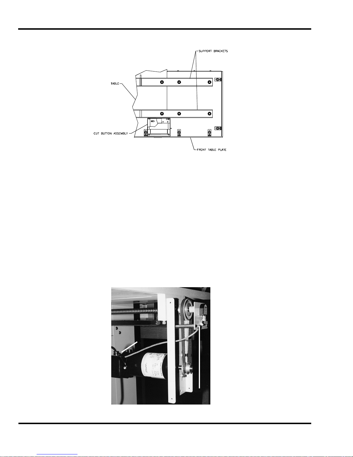
Make sure power is disconnect ed from the machine. Remove the f r ont t able plate (Figure 4) by
removing the hex nut s. Rem ov e the extension table hardware and remov e extensi on tables.
NOTE: There may be shims locat ed between the extension tables and the ext ensi on table brackets.
These are used for l ev eling the extension tables at the factor y . Take not e as to where they are
located so they c an be plac ed in the proper posi tion when reattaching the extension tables later.
11
Page 12
5.0 Installati on & Setup
g
Now remove the two extensi on table support brackets (Figure 4).
View from underneat h table
Figure 4
5.4.2 Removing the Table
Make sure the knife has been removed from the machine and that the knif e and clamp ar e in the “up”
position. If they are not , read the Power Hookup Section (page 17) to connec t power to the machine.
Turn on the power using the red and y ellow main power switch, and press the CLEAR butt on. This
will preset the back gauge and send the k nife and clamp up.
Turn off the machi ne and disconnect the power.
Make sure the extension tables have been removed (page 11). Remov e the 2-hand button controls.
Remove the sheet metal c ov er s fr om the r ear of the t able. Remove the backgauge motor cover, the
lower back panel, and the lower front cover of the machine.
Unplug the cabl e to the encoder at t he bac k of the machine (Figure 5). Remove the motor juncti on
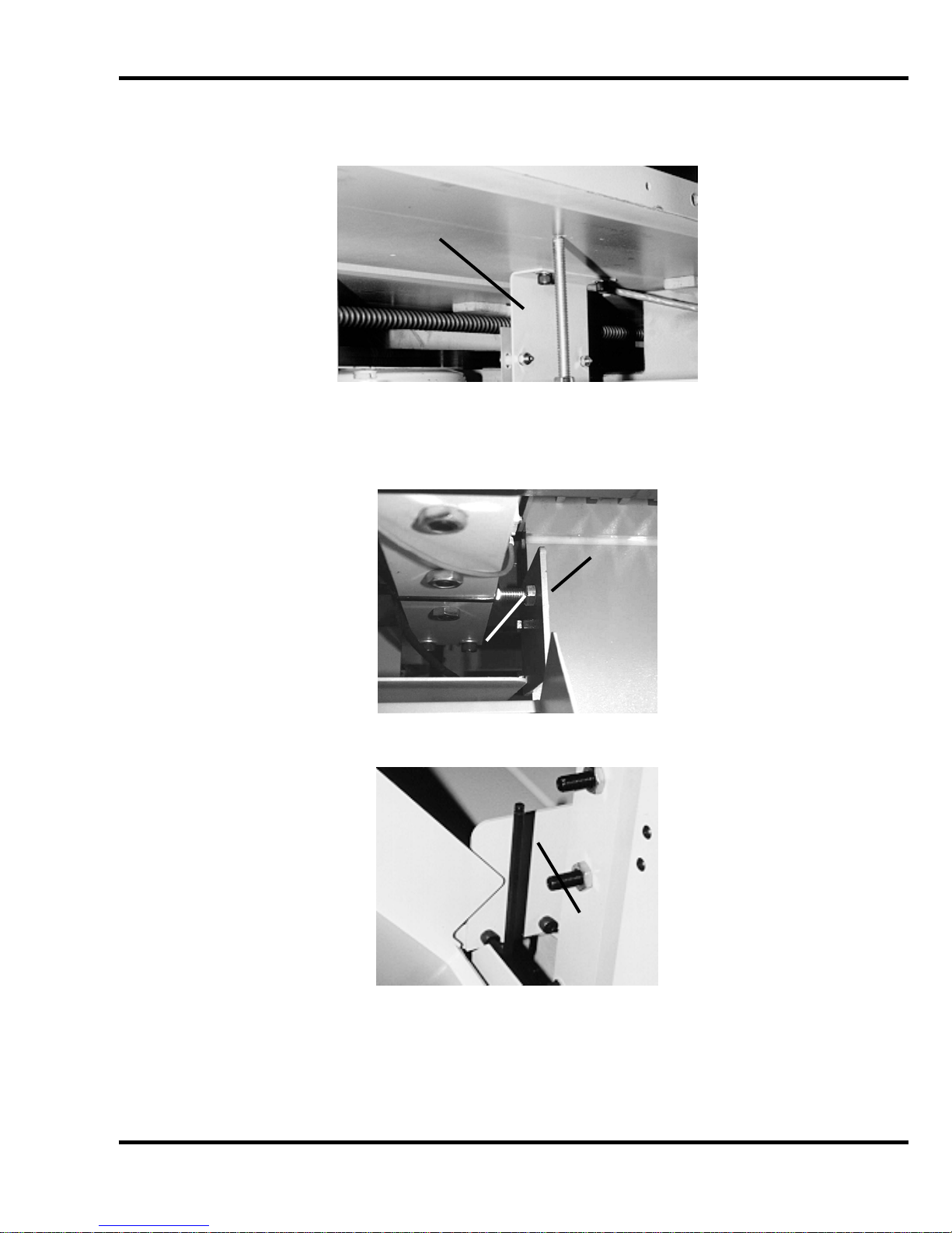
box cover and disconnect the wires to the motor (Figure 5). Rem ov e the leadscrew cover and the
nylon tyraps that ar e att ac hed to the bottom of the table. The motor wires and encoder wires shoul d
now be free from the tabl e.
12
Motor
Junction
Box
Figure 5
Encoder
Plu
Page 13
5.0 Installati on & Setup
Remove the preset board assembly from the bottom of table (Figur e 6) .
Preset Board
Assembly
Figure 6
Open the top hood and loosen the jam nut on left hand side guide support screw and turn it in a few
turns for clearance, then remove the left and right si de guides as shown in Figure 7 & Figure 8.
Left Side
Guide
Side Guide
Support Screw
Figure 7
Right Side
Guide
Figure 8
Remove the two taper pins from the bottom side of the table by tightening the jam nut on the taper
pin. Then remove the f our screws that mount the table to the base. CAUTION: the table assembl y
is very heavy and requi res at least four people to remove. Pull the table out towards the back of
the machine.
13
Page 14

5.0 Installati on & Setup
5.4.3 Removing the Electric Eyes
Make sure power is disconnect ed from the machine. Open top cov er. Remove the four hex -head
screws for each el ectri c ey e assem bly from the inside of the machine. By slidi ng some of the sl ac k in
the cable through t he si de of t he m ac hine, t he ey e assem blies can be set on the machine. If it is
necessary to completely remove the eyes from the machine, the wires must be disconnected from t he
power panel.
5.4.4 Removing the Footswitch
Make sure power is disconnect ed from the machine. Remove lower fr ont cover. Remove the two
screws that mount the f ootswitch bracket (Figure 9). Lay footswitch assembly inside t he m ac hine.
Mounting
Screws
Figure 9
5.4.5 Attaching the Table
Set the table in posi tion, and start its front two mounting screws. Then start the rear two mounti ng
screws. Replace the t wo taper pins (must be snug to seat the table), and then tighten all four screws.
Attach the right and left si de guides then re-adjust the left hand side guide support screw until it
contacts the side guide and tighten the jam nut. (Figure 7 & Figure 8 on page 13), the preset board
assembly (Figur e 6 on page 13) , t he m otor and enc oder wir e ( Figure 5 on page 12) and all guards
and panels.
Once the table is instal led, the backgauge squareness and accur ac y m ust be r eadjusted. See the
Titan 265 Technic al S ervice and Parts manual for information on how to do this.
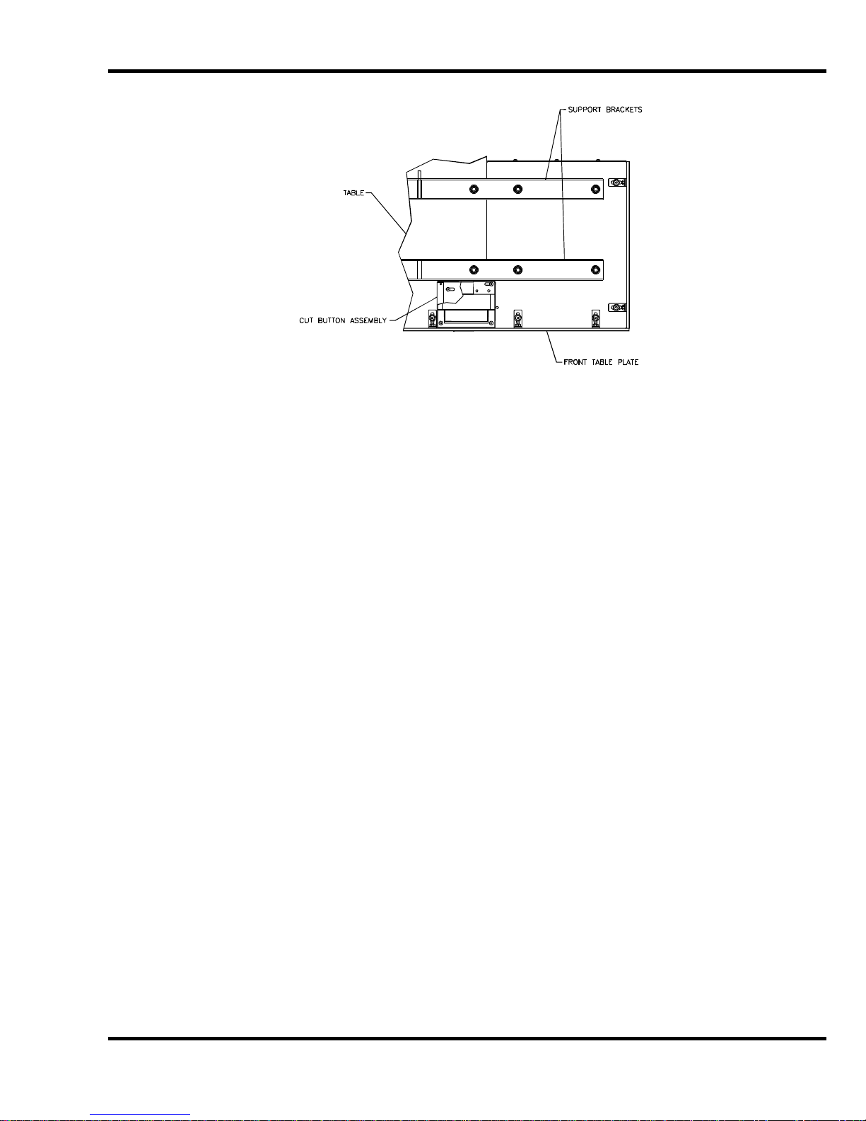
5.4.6 Attaching the Extension Tables
Attach the ext ensi on table support brackets to the under side of the main table as shown in Figure 10,
but do not tight en screws completely. Route each cut button wire thr ough the slots in the brackets
while attachi ng them. Next, place any shims that were instal led at the factory in the positi on they
were in when the extension tables were removed. Lay the table extensions in place and insert the
screws. Align the front edges of the tables and tighten screws. Attach the front table plate.
14
Page 15
5.0 Installati on & Setup
Figure 10
5.4.7 Attaching the Electric Eyes
Make sure power is disconnect ed from the machine. If necessary, connect the wires to the power
panel. Attac h electri c ey e assemblies with provided hardware, m aki ng sure that the bottom of the
electric ey e housings are paral lel to the table. Once power is hooked up, the electric eyes should be
checked for alignment. See the Titan 265 Technical Servic e and P arts manual for information on how
to do this.
5.4.8 Attaching the Footswitch
Make sure power is disconnect ed from the machine. Attach the foot switc h br acket using the
mounting hardware (F igure 9, page 14).
5.5 Hydraulic System Check
The Titan 265 is powered by a hydraul ic system consisting of an electric m otor c oupled directly to a
hydraulic pump.
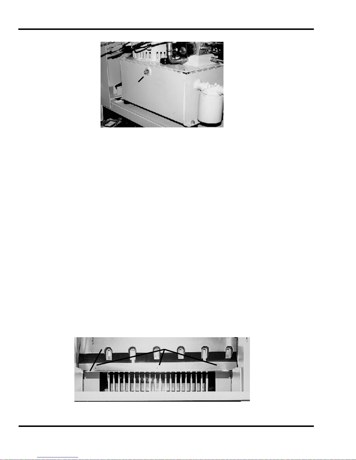
The hydraulic r eservoir holds 5 gallons of hydraulic fluid. It is filled with Tellus #46 hydraul ic fluid at
the factor y but shoul d be c hec k ed before operation. Remove the lower rear panel c ov er. Check the
sight gauge on the rear si de of t he hy dr aulic tank. Fluid should just be vi si ble in the si ght gauge
(Figure 11, next page). Add fluid if necessary, but avoid overfilling. For more inform ation about
checking and changing the hydraulic fluid, including a cross-referenc e c har t of appr ov ed fluids, See
the Titan 265 Technical Service and Parts manual. When finished, replace the panel.
15
Page 16
5.0 Installati on & Setup
Sight
Gauge
Figure 11
The hydraulic fluid should be checked weekly and changed AT LEAST ONCE-PER-YEAR or after
every 1,000 hours of operation.
5.6 Optional Fals e Cl am p Plat e
To prevent marking on pressure sensitive jobs, a false clamp plate is availabl e as an optional item for
your machine. Thi s pl ate attac hes to the bottom of the clamp. It is secured with (3) setscrews
located in holes on the lower front face of the clamp.
To insta ll :
1. Make sure t he k nife and clamp are in the up position. If they are not , t ur n on the power using
the red and yellow mai n power swit c h. Press the CLEAR button. This will preset the
backgauge and send the knife and clamp up.
2. REMO V E KNIF E. See Section 7.1 Knife Removal, page 41.
3. Turn the power off and disconnect the power cord.
4. Sli de the false clamp plate under the cl am p and slide the plate up into position.
5. Hold the plate in position and secure with the (3) setscrews located in the lower f r ont f ace of
the clamp, Figure 12.
6. A sensor det ec ts that the false clamp is installed and the computer setting will automatically
be set to ON.
NOTE: The minimum cut with the false clamp plate attached is 1-7/8”.
False Clamp Plate Set Screws
16
Figure 12
Page 17

5.0 Installati on & Setup
5.7 Power Hook-Up (208/230 50/60Hz)
For satisfact ory oper ation, be sure that your cutt er is wired for the correct phase and v ol tage and has
adequate power. The c orrect elect rical specifi cations for your machine are shown on the seri al plate.
Check the machine serial plate before connecting the power. For future reference, transfer this
information to the front cover of this manual.
Watch Setup Voltage- Inadequate power to the cutter can be a major source of problems. Too
many machines on the same circuit will reduce the power to each machi ne. Inadequate v oltage wil l
frequently cause overheating, loss of power, and in extreme cases, failure to operate. Test your
voltage when the shop is at actual working level s. Challenge recommends a dedi cated line wit h a
lockable di sconnect to provide adequate power f or this machine.
CAUTION: SHOCK HAZARD! Always disconnect power at main
power panel befo re working on the cutter. Lock it out to prevent accidental power up. (S ee
Power Loc kout Procedure page 5).
Important: You must have an adequ at e si ze ci rc uit and heavy enough wir ing for this mac hine. T he
circuit size should be a minimum of 20% greater than the amperage rating on the machine
nameplate. If a wire is run over 75 feet ( 23 meters), the next siz e wire should be used. Check local
electric al c odes.
Electrical Sp ecifications for the Titan 265:
Three Ph.: 208/230 V 25 A 30 A #10 AWG
Voltage Amperage Circuit Size Wire Size
Single Ph.: 208/230 V 30 A 40 A #8 AWG
‘XT’ models – ther e are two places that must be set for the proper incoming v oltage. The first is the
terminal bloc ks found in the power panel. Check incoming voltage and position the Termi nal Block
Jumper for the proper v oltage selection location as shown in Fi gur e 13.
Voltage Amperage Circuit Size Wire Size
Figure 13
17
Page 18

5.0 Installati on & Setup
NOTE: The terminal block jum per must be set t o the correct location according to the supply voltage
of the machine. Failure to set the t erminal block jumper will cause damage to the machi ne!
The second place that must be set for the proper incoming voltage is the transformer terminal stri p
behind the control console. Check the incoming voltage and move wire #21 to the proper terminal as
shown in Figure 14
Figure 14
NOTE: The terminal block jum per must be set t o the correct location according to the supply voltage
of the machine. Failure to move wire #21 to the proper terminal will cause damage to th e
machine!
The power source is connect ed to the cutter at in the junction box loc ated at the rear , r ight hand side
of the machine.
5.7.1 Single Phase Hook-Up
1. Disconnec t the power at the main power panel and l ock it out to prevent accidental power-up.
See Power Lock-Out pr oc edur e, page 5.
2. Thread the power cord through the knock - out hole in the junction box located near the fl oor in
the lower left hand c or ner of t he machine rear. Secure it with a conduit connector.
3. Fasten the ground lead to the ground terminal lug found in the junction box.
4. Use wire nuts to join the two power leads to the L1 and L2 leads found in the junction box.
5. Close al l doors and guards, unlock the main power and swit c h it on. The machine should
now have power.
5.7.2 Three Phase Hook-Up
1. Disconnec t the power at the main power panel and l ock it out to prevent accidental power-up.
See Power Lock-Out pr oc edur e, page 5.
2. Thread the power cord through the knock - out hole in the junction box located near the fl oor in
the lower left hand c or ner of t he machine rear. Secure it with a conduit connector.
3. Fasten the ground lead to the ground terminal lug found in the junction box.
18
Page 19

5.0 Installati on & Setup
4. Use wire nuts to join the three power leads to the L1, L2 and L3 leads found in the junction
box.
5. Close al l doors and guards, unlock the main power and swit c h it on. The machine should
now have power.
6. Press both cut buttons simultaneously to activate the motor and check to make sure it is
turning the same dir ec tion as the arrow on the motor casing. If it isn’t, disconnec t the power
and simply exc hange any two leads of the power cord as in Figure 15. The motor will now
turn the corr ect dir ec tion. Double check to make sure.
1
2
31 2
3
Figure 15
5.8 Power Hook-Up (380/400/415V 50Hz) – also applies for (460V
60Hz)
For satisfact ory oper ation, be sure that your cutt er is wired for the correct phase and v ol tage and has
adequate power. The c orrect elect rical specifi cations for your machine are shown on the seri al plate.
Check the machine serial plate before connecting the power. For future reference, transfer this
information to the front cover of this manual.
Watch Setup Voltage- Inadequate power to the cutter can be a major source of problems. Too
many machines on the same circuit will reduce the power to each machi ne. Inadequate v oltage wil l
frequently cause overheating, loss of power, and in extreme cases, failure to operate. Test your
voltage when the shop is at actual working level s. Challenge recommends a dedi cated line wit h a
lockable di sconnect to provide adequate power f or this machine.
power panel befo re working on the cutter. Lock it out to prevent accidental power up. (S ee
Power Loc kout Procedure page 5).
Important: You must have an adequ at e si ze ci rc uit and heavy enough wir ing for this mac hine. T he
circuit size should be a minimum of 20% greater than the amperage rating on the machine
nameplate. If a wire is run over 75 feet ( 23 meters), the next siz e wire should be used. Check local
electric al c odes.
Electrical Sp ecifications for the Titan 265:
Three Ph.: 380/400/415V 50Hz 15 A 30 A #10 AWG
460V 60Hz 11.5A 25 A #10 AWG
Voltage Amperage Circuit Size Wire Size
CAUTION: SHOCK HAZARD! Always disconnect power at main
19
Page 20

5.0 Installati on & Setup
Check the incoming voltage – if it is different from the factory set 415V, the tap on the main
transform er must be changed t o m atch the incoming voltage - see Figure 16 below for the procedure
The following also appl ies for 460V 60Hz Hook-ups – use taps H4 and H1.
Figure 16
The power source is connect ed to the cutter at in the junction box loc ated at the rear , r ight hand side
of the machine. The power i s then r un up to t he m ai n transformer mounted to the side of the machine,
under the top hood.
5.8.1 Three Phase Hook-Up
7. Disconnec t the power at the main power panel and l ock it out to prevent accidental power-up.
See Power Lock-Out pr oc edur e, page 5.
8. Thread the power cord through the knock - out hole in the junction box located near the fl oor in
the lower left hand c or ner of t he machine rear. Secure it with a conduit connector.
9. Fasten the ground lead to the ground terminal lug found in the junction box.
10. Use wir e nuts to join the three power leads to t he L1, L2 and L3 leads found in the junction
box.
20
Page 21

5.0 Installati on & Setup
11. Close all doors and guards, unlock the main power and switch it on. The machine shoul d
now have power.
12. Pr ess both cut buttons simultaneousl y to activate the motor and check to make sure it is
turning the same dir ec tion as the arrow on the motor casing. If it isn’t, disconnec t the power
and simply exc hange any two leads of the power cord as in Figure 17. The motor will now
turn the corr ect dir ec tion. Double check to make sure.
1
2
31 2
3
Figure 17
5.9 Line Light
The Titan 265 is equipped with two lights, which provide a line of li ght on the paper in the
approxim ate loc ation of where the paper will be cut. The lights come on when power to the machine
is turned on. The light from eac h bulb r eac hes t he table after passing between the knife and cl amp.
Each light is foc used with a socket head capscrew see Figur e 18
To Adjust:
1. Pl ac e a wi de sheet of paper on the cut stick to view the line light.
2. Using a 3/16” hex allen wrench, turn one of the cap screws until you see a 1/16-1/8” beam.
NOTE: it is best to start by turning the screw clockwise. If the screw turns all the way in
before a line appears, begin turning the screw counterclockwise.
3. Similarly, turn the adjustment screw of the other bulb, until one c ontinuous beam is seen
across the cut stick.
Line Light
Adj. Screws
Figure 18
21
Page 22

5.0 Installati on & Setup
SHOCK HAZARD! Always disconnect power at main power panel
before working on the cutt er. Lock it out to prevent accidental power up. See Power Lo ckou t
Procedure, page 5.
Bulb repl acement:
1. Make sure power is off (see Power Lockout Proc edur e, page 5).
2. Rem ov e the old bulb by lightly pushing the bulb into the socket and turning it 1/4 turn
countercl oc k wise. CAUTION! If the bulb is still hot, allow a few minutes for it to cool.
3. Insert the new bulb into the socket, push it in and twist it cl ockwise until the bulb locks i nto
place.
4. Reconnect power and t ur n the main power switch on. Readjust the line if necessary.
22
Page 23

6.0 Operation
6.0 Operation
IMPORTANT: DO NOT ATTEMPT TO OPERATE THE CUTTER UNTIL YOU HAVE
THOROUGHLY READ AND UNDERSTAND ALL OF THE FOLLOWING INST RUCTIONS. CALL
YOUR AUTHORIZED CHALLENGE DEALER IF YOU STILL HAVE ANY QUESTIONS.
6.1 Main Power and Start Up
Figure 19 - Main Power Switch
Power is brought to the m ac hine when the main power switch is turned to t he “ON” position (Figure
19). The Lower and upper boards receive power and line lights are turned on at t hi s time. The LCD
screen does not light up for approximately one minute. The program st ar ts and waits for the ‘Clear’
button to be pressed. The upper boar d then queries the lower board f or the settings and checks them
against it s settings. If they both agree, the startup continues. T he bac k gauge moves to the preset
location and wait s for user input. If they do not agree, once the backgauge reac hes the pr eset, a
window will show asking f or user input to choose which board is correct. After the values are set the
cutter is ready t o use.
If the knife and clamp are not in the “up” position, the display will prom pt the
operator to raise them by pr essing t he cut buttons prior to presetting the backgauge.
The screen saver will activate and the line lights will shut off after 5 minutes without any activit y. This
shut-off time c an be changed i n the Par am eters screen of the Maintenance Mode. To rest or e power
to the display and line lights, press any button on the keyboard or touch the screen.
6.2 Making a Cut
Place the paper agai nst the backgauge and side guide. Press and release both c ut buttons once to
start the hydraulic motor. Then press and hold both cut buttons to star t the cut cycle. While holding
the cut buttons, t he k nife and clamp will complete the cut cycl e. If the but tons are released at any
time during the cy cl e, t he k nife and clamp will immediately return to the up position.
Both cut buttons must be released before a new cut can be made. Also, the cut
buttons must be pressed wit hin 0.5 seconds of each other in order to initi ate a cut.
CLAMP HAVE STOPPED IN THE UP POSITION! Due to static buildup, fine trim may have a
tendency to stick to the clamp or knife surfaces. Fingertips might be d rawn into the knife by
DO NOT ATTEMPT TO REMOVE TRIM UNTIL THE KNIFE AND
23
Page 24

6.0 Operation
the clamp if this is attempted. Wait until the knife and clamp have BOTH STOPPED MOVING
before removing stock t rim.
The hydraulic m otor c an be shut off at any tim e by pr essing t he ‘S top Motor’ button or pressing and
holding one cut but ton for about five seconds. The hydraulic motor will also shut off when the screen
saver is activ ated. This shut-off time can be changed in the Param eters screen of the Maintenance
Mode. (See Section 6.1.3 – Figure 14)
6.3 Air Table Option
Machines equipped wit h an air table option can have the air table feature turned on or off by pressing
Air Table ON/OFF key or by pressing and holding the left cut but ton for three seconds.
6.4 Jogging Aid
All Titan 265 cutter s i ncl ude a jogging aid as standard equipment. The jogging aid allows the
operator to load and align stock without placing hands or arm s under t he cl am p and k nife area.
Figure 20
Load and align the paper against the side guide (Figure 20), t hen square it to the backgauge for
cutting.
Always remove the jogging aid from the t abl e before maki ng a cut.
Additional j ogging aids can be purchased by contacting your authorized Challenge deal er .
6.5 Adjusting the Clam p Pr ess ur e
Touch the 'Clamp Pressure' num ber or the 'False Clamp' symbol and a set of arrows will appear.
Touch these arrows to vary the pressure. The pressure scale ranges from 0 to 15, 15 being the
maximum. (See Section 6. 12.2 B, C and D)
6.6 Pre-Clam pin g
The Titan 265 is equipped with a low-pressure clamping feat ur e, which allows the operator to cl am p
paper under low pressure bef or e beginning the cut cycle. To use this feature, press down on the foot
24
Page 25

6.0 Operation
switch loc ated at the front of t he m achine until the clamp comes down on the paper. To raise the
clamp, rel ease the foot switch. To make a cut, keep the foot switch pressed and press the c ut
buttons. Release the foot switch once the cut has been complet ed. Avoi d placi ng hands under t he
clamp.
6.7 Electric Eyes
The electric ey es prevent reaching into the cutti ng ar ea while a c ut is being m ade. If the beams are
broken while a cut i s bei ng made, the knife and clamp will return to the up posi tion.
6.8 False Clamp Plate
The false clamp plate is an optional attachment, whic h reduces the cr easi ng of paper caused by the
clamp. The disadv antage of using the false clamp plate is that it limi ts the smallest cut dimension.
The machine has a built-i n sensor that detects when the fal se clamp plate is installed, and the
computer will automatically restrict the backgauge position accordingly.
6.9 Sleep Mode
The Sleep Mode starts after a time of inactivity. This is to save the screen and other par ts of the
cutter from wear. Touch the screen, press a cut button or press a key on the keyboard t o bri ng the
cutter out of Sl eep Mode. To change the Time Out for the Sleep Mode see Section 6.15. 1.3 under
‘Maintenance - Memory’.
6.10 Display Panel
6.11 Definiti on of Ke ys
6.11.1 Touch Screen
The touch screen can be used to mak e m any selections. Use by touching the appropriate area with a
light touc h of your finger . Do not use sharp objects such as a ballpoint pen when using the touch
screen.
Figure 21 - Console Layout
25
Page 26

6.0 Operation
6.11.2 Backgauge Glide Control
The Backgauge Glide Control is used to manually position t he backgauge. The speed of the
backgauge will depend upon where the ac tuator is pressed. Press farther from center for a faster
speed and closer to center for a slower speed. To move the backgauge for ward, pr es s do wn ward.
To move the backgauge backward, pr es s up ward. P r es si ng the center displays true posi tion.
6.11.3 IN/MM Key
This key toggles the display to show the position and programmed send values in inches (e.g. 5.250),
inch fractions to the nearest 1/64” (e.g. 5_1/4) , or millimeters (e.g. 133.3).
6.11.4 Air Table ON/OFF Key
This key turns the ai r pump on and off.
6.11.5 CANCEL Key
The CANCEL key closes the current m ode. Some modes need multiple presses of CANCE L to
return to the Send mode.
6.11.6 SEND Key
The SEND key is used to send the backgauge to any valid position. If an att em pt is made to send the
backgauge to an illegal position, an error message will be displ ay ed. In the Job mode, the SEND key
will move the backgauge t o the location in the Current Cut box (S ee S ection 6.12.3 ).
The job must be open and running to send to t he loc ation in the Current Cut box.
6.11.7 Push-Out Key
The push-out key will move the backgauge forward 5 inches (127 MM) (or to the most forward
position) and then return it to its previous positi on. This allows paper to be removed from the c utt er
without putti ng hands under t he k nife and clamp.
26
Page 27

6.0 Operation
Never place hands in the clamp and knife area. Use the push-out key
or the backgauge gli de c ontrol to move the paper to an area where it can be reached.
6.11.8 CLEAR Key
The CLEAR key is used to clear err or messages or the cur r ent entry line.
6.11.9 ENTER Key
The ENTER keys select options and stores typed data.
6.11.10 Priority Add (X/Y) Key
The Priority Add key is used f or entering fractions when they are c om bined wi th whole numbers. The
symbol display ed when this key is pressed is the underli ne symbol “ _”. An exam ple of a number
entered using the Pri or ity Add key is 1_1/2.
6.11.11 Arrow Keys
The four arrow keys can be used in almost all screens. The arrow keys are prim aril y used for moving
the cursor around on the screen, or to toggle between highlighted selections. In some screens, the
left arrow key act s as a backspace key.
6.11.12 PAGE Keys
The PAGE keys are used with li sts. Pressing a PA GE key when a job is open moves the cut location
eighteen cuts. If the c ut location is beyond the first or last cut, the PAGE k ey s mov e to the fir st c ut
(PAGE Up) or to the last cut (PAG E Down). Pressing a P A GE k ey when a li st of jobs is di splayed will
move ten lines to displ ay m or e of the li st.
27
Page 28

6.0 Operation
6.12 Interfac e
6.12.1 Icons
Load Zone
Clamp Only
Cut and Record
Air
Job Locked
Disk or USB Storage Device
Cutter
Help
28
Page 29

6.0 Operation
6.12.2 Main Window
J
L
B A C E
M
D G
H F
N O
I
K
Figure 22 - Main Window
A. Backgauge location
B. Clamp Pressure (0 – 15)
C. False Clamp Indicator
No False Clamp | False C lamp On
D. Clamp Pressure Change
E. Job Name
F. Clamp Only / Load Zone Indicator
G. Locked Job Indi c ator
H. Curr ent Cut Number
I. Job Timer (Touch t o get mor e information)(See Section 0)
29
Page 30

6.0 Operation
Figure 23 - Job Timer
Additional Information
J. Edit Box
K. Job Statistics (See Section 6.12.3 ,Figure 24)
L. Help Button
M. Air On/Off indicator. Also used for the ‘Air Off’ option in an open job.
N. Job S tatistics Icon Referenc e ( Not F unc tion Keys)
O. Function Key Colum n
6.12.3 Job Statistics
List Pictur es
Previous Cuts
Current Cut
More Cuts
Hours: Minutes
• List Pictures
The List Pictures show graphic ally what inform ation each column contains.
The Clamp Only/Load Zone c olum n shows that when there is a ‘C’ (Clamp Only) or an “L”
(Load Zone) in the cur r ent cut t her e wi ll be no c ut made for that location, but the Backgauge
will advance to the next position in memory.
If there is an "X" in the Push Out Col um n, the backgauge will not perform a push out when
going to that position. When there is a "P" in the cut the backgauge will be for c e d to perform
a push out when going to that position.
An “X” in the current cut of the Air Off column overrides the table air tur ning it off when
moving to that cut. The air turns back on again after the next cut.
30
Figure 24 – Job Statisti cs
Page 31

6.0 Operation
There are four options in the Turn column. The symbol “<” means rotate t he lift left
(clockwise) 90° and r eplace it against the backgauge. The sym bol “<<” m eans rot ate the lift
180° and replace it agai nst the backgauge. The symbol “>” means rotate t he lift ri ght
(counter clock wise) 90° and r eplace it against the backgauge. The symbol “B” means bring
back a previous lift to finish it (automatic programming only).
The Pressure column allows you to set the clamp pressure for the curr ent cut.
• Previous Cuts
The previous cut s rows are the cuts t hat have already been made or passed. See Section
6.11.11 and 6.11.12 for more inf ormation on how to move around in a job.
• Current Cut
The cut contai ned in this row is the current cut of the job.
• More Cuts
The More Cuts rows contain t he nex t nineteen cuts of the job.
6.13 Jobs
6.13.1 Programming a Job
6.13.1.1 Manual E ntry / By Cut
Select 'New Job' from the 'J ob' m enu or 'New Job' f r om the function key column. Select 'Manual
Entry' and fill in the box with the job name.
All cut positions for the job will be entered in the 'Edit Box'. If there is not a number in the 'Edit Box'
the current bac k gauge posi tion will be used when 'Enter' is pressed or a cut is made. Any new
position can be entered from the number keys, the result fr om a math formula or sending to a location
and then pressing 'Enter' . Each successive position wil l appear below the previous positi on in the
programming c olum n.
Options may be entered to the cut position line using the func tion keys. Pressing the yellow up and
down arrows changes clamp pressure number. 'Load Zone' "L" indicates load zone position (no cut
or clamp). 'Turn' "<" indic ates turn lift clockwise. 'T ur n' ">" indic ates turn lift countercloc k wise.
'Turn' "<<" indicates turn lift 180 degrees. ' P ush Out' "P" indicates a push out and "x" indicates no
push out for that cut. 'Ai r ' "x" indicates the air off between cuts.
When one cut positi on is complete, repeat the same procedure f or the nex t position. The blue box
will turn yellow when the value inside is a send value or if the sli de bar for the back gauge is used. To
save this value, pr ess 'Enter ' . Press 'Finish' when the program is compl ete.
In the 'Manual Job' there is a 'Cut Rec or d' option. This allows the operator to make cut s and the
location of the c ut is entered automatically into the new job. The job is incremented and is ready for
the next cut. To start the 'Cut Rec or d' mode press the 'Cut Rec or d On' function button while m aki ng
a 'Manual Job'.
31
Page 32

6.0 Operation
6.13.1.2 Sheet Division
Figure 25
Select 'New Job' from the 'J ob' m enu or 'New Job' f r om the function key column. Select 'Sheet
Division' and fi ll in the box with the job name. The program will ask if you want 'Pre- Trims'. 'PreTrims' are entered just like a 'Manual' job. Press the 'Pre-Trims Done' function button when the 'P r eTrims' have all been entered. Enter the dimensions of the 'Parent Size' and the dimensions of t he
'Finish Product'. Use the up and down arrows to move from one dimension to the next or press
'Enter' when the value is complete. The left arrow key is a backspace. Set t he ' Clamp Pressure'
using the number keys fr om 0 to 15. Select " Ai r off between cut s", "Allow cross grain cuts" and " Cut
columns separately " by touching the box. Choose 'Finish' to move on to the 'Layout' screen.
On the 'Layout' screen, sel ec t the layout that best suits the job. Press 'Next Layout' or touch the text
of the desired layout to view each option. To enter new numbers without star ting over, press the
'Reenter' button. Press the 'Accept Layout' when the desired layout is selected and the c utt er will
calculate the new job. The Layout should be saved to the cutter m emory or to a disk. The 'Save
Job' window will show when the new job i s ready ( see 6.13.4 " S av ing an Open Job" for help in saving
a job).
6.13.1.3 Label Cut
Figure 26
Select 'New Job’ f r om the 'Job' m enu or ' New Job' from the function key column. Selec t 'Label
Cutting' and fill in the box with the job name.
The program will ask for two 'Pre-Trims'. 'Pre-Trim s' are enter ed just like a 'Manual' job. Press the
'Pre-Trim s Done' f unc tion button when the 'Pre-Trim s' have all been entered.
Enter the quanti ty of the finished pieces horizontal and v ert ical, the dimensions of the 'Finish Product'
and the dimensions of the 'Gutters'. Use the up and down arrows to move from one dimension to the
next or press 'Enter' when the value is complete. The left arrow key is a backspace. S et the 'Clamp
Pressure' using the number keys from 0 to 15. Select "Air off between cuts" and "Cut columns
separately" by touching the box. Choose 'Finish' t o m ov e on to the 'Layout' screen.
32
Page 33

6.0 Operation
A
On the 'Layout' screen, sel ec t the layout that best suits the job. Press 'Next Layout' or touch the text
of the desired layout to view each option. To enter new numbers without star ting over, press the
'Reenter' button. Press the 'Accept Layout' when the desired layout is selected and the c utt er will
calculate the new job. The Layout should be saved to the cutter m emory or to a disk. The 'Save
Job' window will show when the new job i s ready ( see 6.13.4 " S av ing an Open Job" for help in saving
a job).
6.13.1.4 Repeat Cut
Press the 'Repeat Cut' opt ion from the function key column. Enter the
length of the lif t in t he 'Back gauge S tart' box and press 'Enter'. Enter
the cut dimension in the 'Step Size' box and press 'Enter' to ac c ept t he
job or 'Exit' to rejec t t he v alues. When the job is accepted the
backgauge will m ov e to the start loc ation and each cut will send the
backgauge to the next 'Step Size' dimension. Press 'Exi t' from the
function key c olum n to close the ' Repeat Cut' job.
Figure 27
6.13.2 Opening a Previously Saved Job
Choose the 'Open Job' option from the 'Job' menu or the 'Open Job' key from the function key
column. Use the arrow keys (on the key boar d) , the arrows on the window, and 'Page Up' and 'Page
Down' keys to scroll t hr ough the job names. If you see the name you want you may also just t ouc h
the name and it will appear as the selec tion. Press the 'Open' functi on butt on or the 'E nter' button to
open the selected job. (SeeFigure 26 for Open Job Window layout. )
6.13.3 Editing an Open Job
Editing an open job is similar to ‘Manual Entry’. Edit the loc ation using the keypad and use the
function button column to change the options. When a job is closed without being saved, the save
window will show. If the changes are unwant ed, press the ‘Exit’ funct ion button to skip saving.
Otherwise, choose either the disk, or the cutter to save it to.
A job written wit h ‘Sheet Div ision’ or ‘Label Cut’ can only have some of its vari ables changed. No
new cuts may be added and no cuts can be remov ed. The options can be changed using the
function key column.
rrows
Selected Job Name
Job Names
Locked Job Indi c ator
Display Options
Disk Space
Open Job, Save Job, Copy Job, Delete Job
Lock/Unlock Job
Buttons (See 5.7)
Figure 28 Job Window
33
Page 34

6.0 Operation
6.13.4 Saving an Open Job
Choose the 'Sav e Job' option from the 'Job' menu or the 'Save Job' key fr om the function key column.
The name of the job can be changed on t he 'Save Job' window. The job can be saved to either the
cutter or a USB Storage Dev ic e. Pr ess the "S av e To: " cutter butt on or "Save To:" disk button (Must
have a USB Storage Devi c e in the driv e before opening the Save Job Window) to save the job. A job
must be open to be saved. (See
Figure 28 for Sav e Job Window lay out.)
6.13.5 Delete a Previously Saved Job
Choose 'Delete J ob' from the 'J ob' m enu. Choose the job t o be deleted from the menu and press the
'Delete' button. The ‘Delete All’ check box allows for erasing all of the jobs on a USB Storage Device
or the cutter. Del eting all files will delete all locked jobs as well. Select the ‘Delete All’ c hec k box and
then delete the jobs on the cutter or the USB Storage Device. (See Figure 10 f or Del ete Job Window
layout.)
Press 'Exit' when finished deleting jobs.
6.13.6 Copy a Job To/From a USB Storage Device
Choose 'Copy Job' option from the 'Job' menu. To copy one job, select the job t o be copi ed and
press the 'Copy' button. To copy all jobs, select the 'Copy All' check box and choose the destination
of the jobs (Cutter or USB Stor age Dev ic e). The 'Copy To:' buttons will copy from the ot her to t he
one selected. (S ee Figure 10 for Copy Job Window layout.)
Press 'Exit' when finished copying jobs.
6.13.7 Locking/Unlocking a Job
Locking a job prevents changes from being saved to the job that i s l oc k ed. A locked job can be
changed and saved wit h a diff er ent name. Jobs can be locked or unlocked from the 'Open Job',
'Save Job', 'D elete Job' and 'Copy Job' windows using the 'Lock (U nlock) Job' button or the 'LockPassword' button. The Lock - P assword button gives an added level to loc ki ng a job si nc e changes
cannot be saved to the job wit hout fi r st unlocking it with the password. When a job is lock ed a
padlock will appear besi de the name on the Job window and next to the open job on the Main
window. (See Figure 22 and Figure 10)
A locked job can be deleted using the 'Delete All' command.
Remember to write down the password for each file for later refer enc e.
6.14 Safety Systems
6.14.1 False Clamp Plate
If a false clamp is in installed, the cutter will detec t it and show the false clamp as “on”.
6.14.2 Safety Eyes
The safety eyes stop the back gauge and pr event a cut. When the backgauge is moving f or ward and
the safety eyes are broken, the backgauge will stop at about 3.5 inches and a message will ask that
34
Page 35

6.0 Operation
the eyes be cleared. The message includes the 'MOVE' button to move the back gauge forward
slowly without clearing the eyes. Pressing the slider will also allow movement.
Safety Beam Broken Message
6.15 Maintenance
There are three options under the ‘Maintenance’ pull-down menu: ‘Maintenance’, ‘Upgr ade’ and
‘Calculator’.
6.15.1 Maintenance
The ‘Maintenance’ window contains six tabs for changing t he variables that affect t he performance of
the cutter: ‘Paramet ers’, ‘Miscellaneous’,’ Memory’, ’ Adjust’, ‘Knife Adjust’ and ‘Language’.
6.15.1.1 Parameters
Settable Variables
Current Values
Figure 29 – Parameters Tab
The ‘Parameter s’ tab has thr ee settable variables; ‘P ush Out On’, ‘Reposition On’, and ‘False Cl am p
On’ (PC version only ). It al so shows the current values of ‘Accuracy Adjust’, ‘K nife Count’, ‘Lube
Count’ and ‘Machine Count ’.
6.15.1.2 Miscellaneous (Misc.)
Figure 30 - Miscellaneous Tab
35
Page 36

6.0 Operation
6.15.1.2.1 Job Timer
Check the ‘Job Tim er ’ check box to turn on the Job Timer. The Job Timer keeps track of the amount
of time a job has been running. Pausing the job will pause the timer as well. Touching the timer
display beside an open job opens a window to more information (See 6.12.2 - I for a picture). The
window shows how many cuts have been made in the open job and how many cuts were made per
minute. If a job is running or paused, t he time cannot be reset. The values may only be reset when
a job is not running. Closing a job r esets the timer.
6.15.1.2.2 Keyboar d Lay out
There are two choic es for the key boar d l ay outs. ‘ABCDEF’ stands for setti ng the keys in alphabetical
order. ‘QWERTY’ stands for setting the keys in the standard keyboar d layout. The keyboards are
used to enter job names, dealer information, etc… (See Figure 31)
6.15.1.3 Memory
Figure 31 – Keyboard Layouts
Clear Knife
Clear Lube
Set Knife
Figure 32 - Memory Tab
The ‘Memory’ tab cont ains buttons to change variabl es in memory. The ‘Clear Saved Errors’ button
removes the stored er r or s fr om the c utter. The ‘Clear Knife’ button clears the Knife Count. The ‘Clear
Lube’ button clear s t he Lube Count. The ‘Knife Reminder’ button allows the user to set the number of
cuts before the ‘Shar pen K nife’ reminder shows on the main window. The ‘Time Out’ box sets the
amount of tim e that will elapse before the cutter goes into sleep mode. ( S ee Secti on 6.9 )
6.15.1.4 Adjust
Clear Saved Errors
Current Values
Time Out
36
Change Button
Figure 33 - Adjust Tab
Page 37

6.0 Operation
To enable the settings on this screen, first press the ‘Change’ button.
Enter code: 1433
Figure 34 - Adjust Tab
Next, in the text box that appear s enter the code: 1433. Then press the ‘Change’ button again. The
screen should now look li k e the one shown in Figure 35 below:
Set Maximum/Minimum Bars
Set Accuracy
Adjust
Send Buttons
Figure 35 - Adjust Tab
6.15.1.4.1 Max / Min Clam p P r essure
Touch the 'Set Maximum' or 'Set Minimum' bar to change the Maxim um /Minimum Clamp Pressure
setting. Press the ‘Send’ button corresponding to the pressure changed to send the new maximum or
minimum pressure settings to the lower board. These buttons al so set the c urrent pressure to 15 or 0
so that the pressure can be tested i n the 'Maintenance' screen by m aki ng a c ut. Repeat t he changes
and cuts until the pressure is set. See the Technical Manual for inst r uc tions on how to adjust clamp
pressure.
6.15.1.4.2 Accuracy Adjust
The Accuracy Adjust window (Figure 36) is used to adjust the accur ac y of t he backgauge. Press the
‘Accuracy’ but ton (Figure 35) to set.
Figure 36
There are three ways to set the A c c ur acy A djust:
Option 1: Measure and Record
After pressing t he ' S et Ac c ur acy Adj ust' button the 'Accuracy Adj ustm ent' window appears. Two
inches (50.8 MM) i s autom atically entered into the 'E dit Box ’. Thi s number c an either be accepted by
pressing 'Send' or a different position entered and pr essing ' S end' . The backgauge will move into
37
Page 38

6.0 Operation
position f or a cut. Place a small stac k of paper onto the table and square it to the middle of the
backgauge. Make a cut and rem ov e the scrap. Tak e the stack and measure it. Enter the length into
the text box and press the 'Ent er ' button. After the cutter has reset, this process may be repeated or
press the 'Fi nish' but ton to return to the 'Maintenance' window. Press 'OK' on the maintenanc e
window to save the new values.
Option 2: Cut and Compare
The second procedure is much like the first. Press the 'Accur ac y ' butt on to start the 'Accuracy
Adjustment' . Two inches (50.8 MM) is automaticall y entered i nto the ‘Edit Box’. This number can
either be acc epted by pr essing 'S end' or a different position enter ed and pr essing 'S end' . The
backgauge will m ov e into position for a cut. Place a small stack of paper great er than 4 inches (102
MM) onto the table and square it to the middle of the backgauge. Make a cut and remove the scrap.
Press Cancel and send the backgauge to half the distance of t he first c ut. Make a second cut . Place
the two halves together . Compare the two stacks to see how closely they match. The stack that was
still against the backgauge is suspect. THE STACK CUT OFF IS THE EXACT LENGTH. Type + or the differenc e between the two stacks based on the stack cut off ( Example +.03 or -.053) and press
'Enter'. After the cutt er has reset, this process may be repeated or pres s t he ' Finish' button to retur n
to the 'Maint enanc e' window. Pr ess 'OK' to save the new values.
Option 3: Send and Record
The third procedur e is for a c oar se sett ing of the Accuracy Adjustment. Press the Acc ur ac y butt on to
start the 'Accurac y A djustm ent'. Two inches (50.8 MM) is automatic ally entered into the ‘Edit Box’.
This number can eit her be accept ed by pr essing ' S end' or a different position entered and pr essing
'Send'. With a ruler, measure the distance from the backgauge t o the cut line on the cut stick. Enter
this distance into the text box and press 'Enter'. After the cutter has reset, this process may be
repeated or press the 'Finish' button to retur n to the 'M aintenance' window. Press 'OK' to save the
new values.
6.15.1.5 Knife Adjust
The ‘Knife Adjust’ (Figure 37) tab provides a way to send the knife up or down (which is necessary to
change or adjust the k nife). To send the knife to the down position, pr ess the ‘Knife Down’ button,
clear the table, and press and hold the cut buttons until the hydr aulic motor stops. To send the knife
to the up position, press the ‘Knife Up’ button and press both cut buttons.
Figure 37 – Knife Adjust T ab
6.15.1.6 Language
In this tab, the user select s the language that will be displayed.
6.16 Upgrad e
38
Upgrade XT Software
Current Help
Update Jobs
Current Language
Page 39

6.0 Operation
• Update Jobs
The ‘Upgrade’ window shows the files that are used with the program and the version number
they are using. The ‘Updat e Cutter’ and ‘Update Disk’ buttons change t he job files previously
saved to the newest ver si on.
• Upgrade XT Program
To install the newest XT upgrade pl ac e the ‘XT Upgrade’ disk (EE-2933- 1- X) supplied by
Challenge into the disk drive. Select the 'Upgrade XT Soft ware' but ton to start the XT Upgrade
program. Press ‘Upgrade’ to start the process. If the disk has an older ver sion of software, the
upgrade program will allow it to be installed. This is useful if t he older software is more desirable
than the new software. W hen upgr ading is complete, shut down the cutter and r estar t it. The
cutter will now run with t he upgr aded software.
Because of changes in the upgrade pr ogr am , the upgrade program ver si ons
previous to 3.01.08.01 do not install all upgrades before the first restart. To rectify this, the XT
software will ask for the upgrade disk to be reinserted when the new XT soft ware is started for the
first time. The final upgrades are then installed and c an be used without restarting the machi ne.
Figure 38 – Upgrade Window
6.16.1 Calculator
The calculator is present for miscellaneous cal c ulating needs. The number calc ulated can be used
as a position if the ‘Send’ key is pressed after the ‘=’ button is pressed. Pr ess the ‘Exit’ button when
finished.
6.17 Diagnostic
6.17.1 Sensor Data
Figure 39 - Sensor Data
39
Page 40

6.0 Operation
The ‘Sensor Data’ area shows the stat us of the inputs and outputs on the cutter. The inputs and
outputs do not update during a cut so the lower board can concentrat e on the safety systems. To
check input sensors that ar e only active during a cut, place a piec e of metal on t he pr ox ' s t o activ ate
them.
DO NOT ATTEMPT TO MAKE A CUT WHILE INSIDE THE CUTTER!
6.17.2 Last Error Code
The ‘Last Error Codes’ window sho ws the last five errors that t he c utt er had. There are ‘Help’ buttons
next to each error f or more information concerning that error. The errors can be cleared in the
‘Maintenance’ window.
40
Page 41

7.0 Knife Installation/Changing
7.0 Knife Installation/Changing
Changing knives can be very danger ous unl es s saf ety precautions are
observed and extrem e c ar e is tak en when handling knives.
• Make sure knife lift er s are proper ly installed, see instructions following.
• Keep handling of unprotected knives to an absolute minimum.
• Clear off cutter table before removing knife.
• Have scabbard on cutter table and insert knife immedi ately.
• Warn people of any unprotected knife.
• Knife changing is a ONE PERSON OPERATION. Having more than one person trying to
change kniv es invites accidents.
5/16”
T-Wrench
Cut Stick
Removal Tool
Figure 40 – Knife Changing Equipment
The knife changi ng equi pm ent shown in Figure 40 is included in the cutter tool ki t. The following
instructions show how to remove and install a new or re-sharpened knife. Read through these
instructions AT LEAST ONCE before attempting to actually change or install any blades.
3/16” Hex
Allen
Wrench
Knife Lifter
Assembly
7.1 Knife Removal
1. Make sure t he k nife and clamp are in the “up” position. Turn the power off and lockout power
to machine, see Power Lockout P r oc edur e, page 5.
2. Back off the knife adjusting screws on top of the k nife bar several turns (Figure 41). A new
knife will cut deeper than one that has been ground several tim es. Failure to back off the
screws could damage t he k nife and/or the cutting stick.
41
Page 42

7.0 Knife Installat io n/ Changing
Knife Adjusting Screws
Figure 41
3. Rem ov e the knife bolts from the two slotted knife bar holes and replace with the knife lifters
(Figure 42). Tighten the lifters to hold the knife in place, and t hen remove the remaining knife
bolts.
Figure 42
4. Clear the table surfaces and place the empt y knif e scabbard on the table. Remove the
scabbard’s knife retaining screws.
5. Grasp t he k nife lifters firmly and, at t he same time, turn them counterclockwise to release the
knife from the knife bar (Figure 43). Lower the left end fi r st, t hen lower t he r ight end as you
shift the knife si deways to the left. Bring the right end of the knif e out from the mac hine. Shift
the knife to the right and bring out the left end. Put the blade in the scabbard immediately and
secure the knife retainer screws.
Figure 43
42
Page 43

7.0 Knife Installation/Changing
7.2 Knife Installation
Knives are heavy and always very sharp! Be sure to keep the edge away
from your body and keep other people out of the area while handling the blade. Severe lacerations or
dismemberm ent could result from careless handling pr oc edur es.
1. Make sure t he k nife and clamp are in the up position. If they are not , t ur n on the power and
press the CLEAR butt on. Once t he bac k gauge is pres et, press both cut buttons to send the
knife and clamp up.
2. Turn the power off and lockout power to machi ne, see Power Lockout P r oc edur e, page 5.
3. Pull out the cutting stick using the cut stick removal tool and turn it to a new surface. If the
cutting sti c k is not l ev el or fl ush with the table, 1/2” strips of paper can be placed in the table
slot under the cutti ng stick to shim it.
4. Rem ov e the left retainer screw from the new blade and screw the knife lifter assembly into
the new blade. Screw the lif ters all the way in and then back them out a 3/4 turn).
5. Rem ov e the other scabbard retainer screw.
6. Double c hec k to make sure the knife adjusting screws have been backed out all the way
(Figure 41, page 42). Guide the blade, left edge first, into the space bet ween the knife bar
guide fra mes on the left. Move the right end of the blade into the machine, under the knife
bar slot. Align the lif ters with the slots in the knife bar, raise the k nife into the knife bar slot as
high as it will go and ti ghten t he lifters.
NOTE: If the blade will not go in, either the lifters are screwed into the blade too far, or the
end of the blade is hitting the cylinder bracket at the ri ght end of the knife slot. In this case,
drop the left end when insert ing the knife.
7. Insert the knife bolts with washers and snug to hol d the knife, but don’t tighten them yet.
8. Rem ov e the k nife lifter assembly and replace with bolts and washers.
9. Pl ac e a few sheets of paper over the cut stick, covering the stick end-to-end.
10. Restore power to machine and turn power on.
11. G o to the MAINTENANCE screen and choose KNIFE ADJUST. Choose KNIF E DOWN, t hen
press and hold the cut butt ons to send the k nife to the down position.
12. T ur n the power off and lockout power to machi ne.
13. T ur n the knife adjusters down evenl y, a littl e at a time, until the knife cuts through the bottom
sheet of paper the entir e length of the cutting stick (Figure 44). Turning the screws down
evenly prevent s uneven wear on the knife and cutting sti ck.
43
Page 44

7.0 Knife Installat io n/ Changing
Figure 44
14. Restore power to machine and turn power on.
15. Pr ess CLEAR. This will raise the knif e and cl am p to the up positi on.
16. T ur n the power off and lockout power to machi ne.
17. T ighten all knife bolts securel y.
18. Restore power to machine and turn power on. Make a test cut through a full lift of paper and
make minor adjustm ents if necessary by repeating steps 9 through 17. NOTE: If the knife
ends cut but the middle doesn’t, you could have dips or uneven spots in the knife and/or
cutting sti c k. These can be eliminated by placing 1/2” stri ps of paper in the t able slot beneath
the cutting stick to shim it.
19. Send the dul l knif e to a k nif e grinder. Do not att empt to sharp en your o wn kniv es! S ee the
Knife Care Tips Secti on below to determine the knife bevel angle.
7.3 Knife Care Tips
! KNIFE SAFETY ! Knives are DANGEROUS!!! They are heavy and very
sharp, even after use. Keep the edge away from your body and keep the area clear of others when
handling knives. Nev er touch the cutting edge! To prevent personal i njur y and damage to the knife,
always keep kniv es i n their holders with screws tightened. You ar e aware of the dangers, but others
may not be. Never attempt t o hone, polish, or service the knife in any way. Failur e to follow safety
procedures may resul t in severe lacerations or dism emberment.
7.3.1 Knife Blade Life
Knife blade lif e, or the time between sharpenings, can be affected by many factors. One import ant
factor is the type of paper being cut. Abrasive paper, such as recycled paper, soft paper such as
newsprint paper, and bound book s can all significantl y shorten knife blade life. Also, if t he k nife depth
is set too deep, the knife will cut too deep into the cutting stick and c an dull the k nife blade.
A knife can last between 2,000 and 5, 000 c uts before it needs to be sharpened. Cutti ng soft paper
(such as newsprint paper) or paper with high post-consumer recy cl ed c ontent can cause the knife to
need sharpening after only 2,000 to 3,000 cuts. Cutti ng pure paper, such as bond paper with no
recycled content, or hard paper can allow the knife to be used for as many as 5,000 cuts before it
needs to be sharpened. In all cases, the oper ator should continually check the quality of the cut to
determine when the knife blade needs to be sharpened. Som e characteristics that indic ate a blade
needs sharpening are:
44
Page 45

7.0 Knife Installation/Changing
• The knife hesit ates or stalls while making a cut.
• The sheets are not all cut t o the sam e length (usually the top few sheets are longer t han the
rest of the sheets - this is sometimes called “draw”).
• Cut marks appear on the cut f ac e of the paper.
• The profil e of the cut (side v iew) is not perpendicular to the t able.
• The cut does not appear straight when viewed from the top.
• The knife makes a “rougher ” sound as it passes thr ough paper.
• Nicks are vi sibl e on the cutti ng edge of the knife.
7.3.2 Cutting Stick
A worn cutting stic k can affect the cut quality of the bottom sheets. W hen this happens, the cut stick
can be rotated. Usuall y, the stick should be rotated one or two times between knife sharpenings.
There are 8 possible cut stick positions. The stick can be rotated 4 times, and then turned end to
end, and rotated 4 times agai n.
7.3.3 Bevel Angle
Challenge recommends that bevel angles for the Titan 265 knives be in the range of 21° to 23°. In
general, a 21° bev el angle will provide better cut quali ty when cutting soft paper (such as newsprint),
recycled paper, or bound books. However, 21° angle kniv es can become dull sooner than 23° knives,
which results in shorter k nife blade life. A knife with a 23° bevel angle, on the ot her hand, will not dull
as easily, and can prov ide satisfactory results when cut ting most types of paper. Knives shipped with
the Titan 265 from the f actor y hav e a bev el angle of 23°.
7.3.4 Helpful Suggestions
If your establishment is large enough to purchase more than one set of knives, have one set
beveled at 21° and the ot her at 23°. Note: A set consists of 3 knives: one in the machine,
one as a back up, and one at the grinder .
If the machine seems to str ain but the cut quality is still good, reduce the pile height. You
may also carefully apply glycerin to the bevel when cutting hard, coated paper. Tie a cloth to
the end of a stick; di p the stick in gly cerin, and apply. Never apply by hand! In lieu of
glycerin you m ay li ghtly rub white bar soap along the bevel. Lubri c ation will prolong the life of
your machine and r educ e m aintenance.
7.3.5 Knife Care
• To prevent corrosion, knives are coated with light oil. It should be REMOVED WITH CARE.
• While removi ng or i nstalling a knife, be careful not to allow the edge to bump against the
machine. Nicks will result.
• If a knife bolt is damaged, r eplace it.
45
Page 46

7.0 Knife Installat io n/ Changing
• Always keep knife bolts securely tightened.
• Always use the heavy - duty knife bolt washers provided by Chall enge. Failure to do so could
result in scratching or marring of the clamp face.
• Store knives in a dry envir onm ent to prevent corrosion.
• Never attempt to service a knife in any way.
46
Page 47

7.0 Knife Installation/Changing
NOTES
47
Page 48

8.0 Oil and Grease
8.0 Oil and Grease
Turn the power off and disconnect the power cord. Open the top hood for access. Part s requiring
oiling are m arked wit h r ed paint. See Figure 45, Figure 46, and Figure 47, for oil and gr ease
locations. Wi pe off any ol d or excess grea se. Use any brand- name type of grease or light oil t o
lubricate.
Note: Machines with seri al numbers 091818 and above no longer r equir e oiling of the knife links. If
your knife li nk s are marked wit h r ed paint as shown below – your knife links do requir e oiling – no red
paint marki ng – oil is not r equir ed.
Grease
Knife Bar
Oil Knife
Link
Oil Knife Link
Grease
Knife Bar
Oil Knife
Cylinder
Pins
Grease
Thrust Washers
Figure 45
Grease Grease
Grease Grease
Figure 46 – Clamp Gibs and Rack & Pinion
48
Page 49

8.0 Oil and Grease
Grease
Figure 47 – Backgaug e Guide
49
Page 50

9.0 Safety Systems Test
9.0 Safety Systems Test
Machine manufact ur er CHALLENGE Model TITAN 265
Serial Number __________________
Frequency of test: THESE TESTS S HOUL D BE PERFORMED AT THE BEGINNING OF EACH
WORK DAY.
Turn the power on and press CLEAR to pr eset the backgauge. Make sure the knife and cl am p are in
the up positi on (if they ar e not, follow the instructions in this manual to send them up).
Test #1: Wave a test object 12mm i n diameter between the electric eye beams. The indic ator lights
should indic ate the eyes are blocked. If they do not, do not use the machine. Repair or adj ustm ent is
needed.
Test #2: While making a cut, lean into the electric eye beams. The knif e and cl amp should
immediately r eturn to the up position. If they do not, do not use the machine. Repair or adjustment is
needed.
50
Page 51

9.0 Safety Systems Test
Please enter date and initials for both tests.
Date ______ ______ ______ ______ ______ ______ ______ ______ ______ ______ ______
Test 1 ______ ______ ______ ______ ______ ______ ______ ______ ______ ______ ______
Test 2 ______ ______ ______ ______ ______ ______ ______ ______ ______ ______ ______
Date ______ ______ ______ ______ ______ ______ ______ ______ ______ ______ ______
Test 1 ______ ______ ______ ______ ______ ______ ______ ______ ______ ______ ______
Test 2 ______ ______ ______ ______ ______ ______ ______ ______ ______ ______ ______
Date ______ ______ ______ ______ ______ ______ ______ ______ ______ ______ ______
Test 1 ______ ______ ______ ______ ______ ______ ______ ______ ______ ______ ______
Test 2 ______ ______ ______ ______ ______ ______ ______ ______ ______ ______ ______
Date ______ ______ ______ ______ ______ ______ ______ ______ ______ ______ ______
Test 1 ______ ______ ______ ______ ______ ______ ______ ______ ______ ______ ______
Test 2 ______ ______ ______ ______ ______ ______ ______ ______ ______ ______ ______
Date ______ ______ ______ ______ ______ ______ ______ ______ ______ ______ ______
Test 1 ______ ______ ______ ______ ______ ______ ______ ______ ______ ______ ______
Test 2 ______ ______ ______ ______ ______ ______ ______ ______ ______ ______ ______
Initials of
Repairs Repairer Date
_________________________________________ ________ _____________
_________________________________________ ________ _____________
_________________________________________ ________ _____________
_________________________________________ ________ _____________
_________________________________________ ________ _____________
_________________________________________ ________ _____________
_________________________________________ ________ _____________
_________________________________________ ________ _____________
_________________________________________ ________ _____________
_________________________________________ ________ _____________
_________________________________________ ________ _____________
_________________________________________ ________ _____________
_________________________________________ ________ _____________
51
Page 52

F.265XT-EO
January 2014
 Loading...