

Page 1

The Challenge Machinery Company provides owner's manuals on its
products s olely as a court esy to i ts cust omers. Se e the inf ormati on belo w
before using this manual.
These manuals are for reference only. These manuals include products which are noncurrent,
unsupported or no longer pr oduced by The Chal l enge M achi nery Com pany , and are pr ov ided sol el y as
an accommodat i on to our c ustom ers. By prov i ding these m anuals, T he Ch al lenge M achi nery Com pany
makes no representation or warranty as to the products, their current condition, or their suitability or
fitness for use in any particular application, which are the sole and i ndependent responsibility of the
product owner and user.
Older produ cts may not co mply with curren t safety pro cedures, guidel ines or regu lat ions, and i t
is the product owner's and user's responsibility to evaluate the suitability and fitness of the
products in their current use and application. The Challenge Machinery Company makes no
representation, warranty or recommendation regarding any modifications which may be
required on non -current o r u nsuppo rted prod ucts. T he Ch allenge Mach inery Co mpan y assumes
no liability for any modification or alteration to any Challenge product, and any such
modification or alteration to any Challenge product is not authorized by The Challenge
Machinery Comp any. The av ailabilit y of t hese manuals is sol el y for t he purpose of provi ding ref erence
information for the products.
This manual may not be complete in all aspects of product maintenance and repair. All products
should be used only by qualified and properly trained personnel, following proper safety
procedures. Al l product s should be regular l y i nspected and m aintai ned, and their condition, appli cation
and use should be periodically evaluated by qualified personnel. Only qualified and properly trained
technicians should perform maintenance, repair and replacement procedures. Attempting these
procedures without pr oper training may cause machine dam age or operat or injury!
Products may be unsup por ted by The Chall enge M ac hinery Company due to age or the unavailability of
parts from their ori ginal m anufactur er. No parts or produc t support will be available to repair or maintain
unsupported prod uc ts. Older products may not be UL listed (if the product does not have a UL l abel it i s
not a listed product), and may not comply with applicable installation or other regulations or
requirement s if rel ocated to a new f acilit y. Many munici palities requi re a product t o be UL l isted bef ore
an electrician will connect power to them. Often the cost of updating an older pro duct to compl y with
current saf ety r egulations is greater than the v alue of t he product .
The Challeng e Machin ery Comp any
6125 Norton Center Drive
Norton Shores, MI 49441-6081 USA
ChallengeMachinery.com
F.265XG-EO
TITAN 265 XG
Operator’s Manual
Serial Numbers 071755 & Up
Sold and Serviced by
January 2014
Page 2

1.0 Introduction
1.0 Introductio n
THIS MANUAL is designed to help you get the most from your Challenge equi pment. Keep this
manual in a safe, conv enient place for quick reference by operators and service personnel.
SAFETY ALERT! This symbol means CAUTION: P erson al saf et y
instructions! Pay special attention to the instructions in bol d ty pe. Personal injury may result if the
precautions are not r ead and followed.
READ THIS MANUAL BEFORE OPERATING! Follow precautions and instr uc tions given and you
should have years of trouble-free operation. If after reading the manual questions sti ll remain, contact
your Authorized Challenge Dealer.
FOR PARTS AND SERVICE contact the Authorized Challenge Deal er fr om whom you pur c hased
your machine. Use the illustrations and parts lists at the bac k of this manual to identify the correct
parts needed. Always give the SERIAL NUMBER and MODEL of your machine to insure t he correct
parts are sent as soon as possible.
Take a few minutes right now to RECO RD YOUR MACHINE S E RIAL NUMBER in the space
provided on the front cover of this manual. Also be sure to fill out the warranty card accompanying
your machine and r eturn it DIRE CTLY TO CHALLENG E.
If you bought a used machine, it is important to have the following information on record at Chall enge.
Copy this page, fill in the information and send it care of The Challenge Serv ice Department, Norton
Center Drive • Norton S hor es • MI 49441-6081.
CHALLENGE MODEL SERIAL NUMBER
ATTN COMPANY
ADDRESS
CITY STATE/PROVINCE ZIP
PHONE DATE INSTALLED
DEALER NAME & CITY
* WARRANTY INFORMATION *
It is very important that y ou r ead and under st and the conditions outli ned in the Warr anty Information
Sheet att ached to the outside of the shipping cont ainer of your machine.
The Warr anty Inf or m ation Sheet must be filled out completely and returned to THE CHALLENGE
MACHINERY COMPANY in order for the warranty to be issued for this machine.
The Challenge Machinery Company• 6125 Norton Center Drive • Norton Shores, MI 49441-6081
Copyright© 2010 by The Challenge Machinery Company. All rights reserved. Printed in the USA
2
Challen ge® is a registered trad em ark of
Page 3

1.0 Introduction
TABLE OF CONTENTS
1.0 Introduc tion................................................................................................................................. 2
2.0 Safety .........................................................................................................................................5
2.1 Precautions............................................................................................................................. 5
2.2 Power Lockout Proc edur e .......................................................................................................5
2.3 Warning Label Definitions........................................................................................................6
3.0 Packing List.................................................................................................................................8
Optional Items .............................................................................................................................. 8
4.0 Specifications.............................................................................................................................. 9
5.0 Installation & Setup ...................................................................................................................10
5.1 Inspecting Shipment.............................................................................................................. 10
5.2 Uncrating.............................................................................................................................. 10
5.3 Cleaning ............................................................................................................................... 11
5.4 Fitti ng Through Nar r ow Door .................................................................................................11
5.4.1 Removing the Extension Tables ..................................................................................... 11
5.4.2 Removing the Table....................................................................................................... 12
5.4.3 Removing the Electric Eyes............................................................................................14
5.4.4 Removing the Footswitch............................................................................................... 14
5.4.5 Atta ching the Ta b le........................................................................................................14
5.4.6 Attaching the Extension Tables...................................................................................... 14
5.4.7 Attaching the Electric Eyes............................................................................................. 15
5.4.8 Atta ching the Fo o tswitch................................................................................................ 15
5.5 Hydraulic System Check....................................................................................................... 15
5.6 Optional Fal se Cl am p Pl ate................................................................................................... 16
5.7 Power Hook-Up (208/230V 50/60Hz)..................................................................................... 17
5.7.1 Single Phase Hook-Up................................................................................................... 18
5.7.2 Three Phase Hook-Up ................................................................................................... 18
5.8 Power Hook-Up (380/400/ 415V 50Hz ) – also appl ies for (460V 60Hz).................................. 19
5.8.1 Three Phase Hook-Up ................................................................................................... 20
5.9 Line Light .............................................................................................................................. 20
6.0 Operation .................................................................................................................................. 22
6.1 Power - Main Power Switch...................................................................................................22
6.2 Start Up................................................................................................................................22
6.3 Making a Cut.........................................................................................................................23
6.4 Air Tab le Option....................................................................................................................23
6.5 Jogging Aid........................................................................................................................... 23
6.6 Adjusting the Clamp Pressure...............................................................................................24
6.7 Pre-Clamping........................................................................................................................24
6.8 Knife Change Al arm and Lubr ic ation Alarm ........................................................................... 25
6.9 Electric Eyes......................................................................................................................... 25
6.10 False Clamp Plate...............................................................................................................25
6.11 Display Panel......................................................................................................................25
6.12 Definition of Keys................................................................................................................25
6.12.1 Backgauge Glide Control ............................................................................................. 25
6.12.2 IN/MM Key...................................................................................................................26
6.12.3 A ir Ta b le ON / OFF Key................................................................................................. 26
6.12.4 Send Key..................................................................................................................... 26
6.12.5 Push-Out Key ..............................................................................................................26
6.12.6 Clear Key.....................................................................................................................26
6.12.7 Enter Key.....................................................................................................................27
6.12.8 Priority Add (X/Y) Key..................................................................................................27
6.12.9 Soft Keys.....................................................................................................................27
6.12.10 Arrow Keys................................................................................................................ 27
6.12.11 Contrast Control (Only on Serial numbers 101876 and below)................................... 27
3
Page 4

1.0 Introduction
6.12.12 Contrast Control (For Serial number s 101877 and Above)...........................................27
6.13 Manual Backgauge Cont r ol..................................................................................................28
6.13.1 Backgauge Glide Control ..............................................................................................28
6.13.2 Backgauge Cont rol Knob..............................................................................................28
6.13.3 Backlash Indicator ........................................................................................................28
6.14 Send Mode..........................................................................................................................28
6.14.1 Entering Math...............................................................................................................29
6.14.2 Entering Fractions.........................................................................................................29
6.15 Repeat Mode.......................................................................................................................29
6.16 Maintenance Mode ..............................................................................................................30
6.16.1 Language .....................................................................................................................30
6.16.2 Parameters...................................................................................................................30
6.16.3 Diagnostic.....................................................................................................................31
6.17 Job Mode.............................................................................................................................32
6.17.1 Lock/Unlocking a Job....................................................................................................33
6.17.2 Copying a Job...............................................................................................................33
6.17.3 Erasing a Job................................................................................................................33
6.17.4 Creating a New Job......................................................................................................33
6.17.5 Editing an Existing Job..................................................................................................37
6.17.6 Running a Programmed Job .........................................................................................38
6.17.7 Exiting a Job .................................................................................................................38
6.18 An Example Job...................................................................................................................39
6.19 Operating Tips.....................................................................................................................39
7.0 Knife Installation/Changing.........................................................................................................41
7.1 Knife Removal.......................................................................................................................41
7.2 Knife Installation....................................................................................................................43
7.3 Knife Care Tips......................................................................................................................44
7.3.1 Knife Blade Life ..............................................................................................................44
7.3.2 Cutting Stick...................................................................................................................45
7.3.3 Bevel Angle....................................................................................................................45
7.3.4 Helpf ul Suggestions........................................................................................................45
7.3.5 Knife Care......................................................................................................................45
8.0 Oil and Grease ...........................................................................................................................48
9.0 Safety Systems Test..................................................................................................................50
4
Page 5
2.0 Safety
2.0 Safety
2.1 Precautions
• This machine i s designed f or one- per son operation. Never operate the machine with more than
one person.
• Safe use of this machi ne is the r esponsibility of the operator . Use good judgment and common
sense when working with and around this machine.
• Read and understand all instructions thoroughl y before using the machine. If questions remain,
contact the deal er from whic h y ou purchased this machine. Failure to under stand the operating
instructions may result in personal injury.
• Only trained and aut hor iz ed people should operate this machine.
• Do not alter saf ety guar ds or devic es. They are for your protection. Severe personal injury may
result.
• Disconnect power bef or e cl eaning or performing mai ntenance. See S ection 2.2 Power Lockout
Procedure.
• Observe all cauti on labels on this machine.
• Be sure the cutter i s properly grounded.
• Be sure there is sufficient power to operate the cutter properly.
• Observe all cauti on plates mounted on this cutter.
• Keep foreign objec ts off table and away from cutter blade.
• BE EXTREMELY CAREFUL when handling and changing the cutter knife. Severe lacerations or
dismemberm ent could result from careless handling pr oc edur es.
• Keep the floor around the cutter free of trim, debris, oil and grease.
• When replacing hy dr aulic parts, loosen the connections slowly to release pressure. Never loosen
connections with the machine running.
• If the cutter sounds or operates unusually, turn i t off and consult the troubleshooting section of
this manual. If the problem cannot be corrected, have it chec k ed by a qualif ied service person.
• CRUSH HAZARD, keep hand and fingers from under the clamp when clamping paper . Use
Jogging Aid to load paper , and use the backgauge to push paper out before unloading. DO NOT
REACH UNDER THE KNIFE AND CLAMP AREA!
2.2 Power Lockout Procedure
For maximum safety when m aki ng adjustments or repairs to your machine, be sure to lock out the
main power control switch to which the machine is connected. The switch should be moved to the
OFF position and a padlock placed in the loop. The key should be held by the person serv icing the
machine.
Figure 1
5
Page 6
2.0 Safety
2.3 Warning Label Definitions
The following warni ng labels are found at various loc ations on your machine. Read and understand
the meaning of each symbol. If a label is lost from the machine, it should be replaced.
HAZARDOUS AREA
Disconnect power bef or e cl eaning, servicing, or m aki ng adjustm ents not requiring
power. Do not alter saf ety guar ds or devices; they are for your prot ection. Replace
all guards. Do not operate with any guards removed.
SHOCK HAZARD
Disconnect power bef or e r em ov ing cover. Replace cover before operation.
SHOCK HAZARD
Disconnect power bef or e r em ov ing cover. Replace cover before operation.
SINGLE OPERATOR
Do not operate with m or e than one person.
6
Page 7

2.0 Safety
!OJO!
This Este simbolo de alerta de seguridad significa ¡ OJO ! INSTRUCCIONES DE SEGURIDADPERSONAL. Lea las i nstrucciones po rque se refieren a su
seguridad personal. Fall de obedecer las instrucciones que siguen podria resultar en lesiones
corporales.
• Esta maquina, junto con sus mecanismos de seguridad, esta disenada para ser manejada por
• UNA SOLA PERSONA a la vez. Jamas debe ser manejada por mas de una persona al mismo
• tiempo.
• La seguridad es la responsabilidad del operario que usa esta maquina.
• LEA DETENIDAMENTE el manual de instrucciones y las PRECAUCIONES DE SEGURIDAD
antes de poner a funcionar la c or tadora. Pidale a su supervisor una copia.
• El manejo de la guill otina debe estar exclusivamente a cargo de per sonal entrenado y autoriz ado
para ello.
• NO MODIFIQUE LOS MECANISMOS DE SEGURI DAD, estan ahi para su proteccion no deben
ni modificar se ni quitarse.
• DESCONECTE LA CORRIENTE ELECTRICA antes de proceder a hacerle servicio de limpieza,
engrasar, o de hacer adjustes que no requieren corrient e. Trabe el interruptor en la posicion
OFF (apagado); vea “Procedimiento para cortar la corriente elect ri c a” al pi e de esta pagi na.
• Eche llave a la guillotina y quite la llave cuando la maquina no esta en operacion; vea “Corriente
electrica”.
• Asegurese de que la guillotina este debidament e a tierra. V ea “Conexion de la fuerza electrica”.
• Verifique el v oltaje y asegurese de que este sea suficient e par a el debido funcionamiento de la
guillotina.
• Preste atenci on a todas las pl ac as con advertencias instaladas en esta guillotina.
• No permita que objetos estranos esten en la mesa o cerca de la cuchilla cort ador a.
• TENGA SUMO CUIDADO al tocar y cambiar la cuchilla. Heridas severas y hasta
desmembrami ento pueden resultar del manejo sin cui dado o negligente.
• El suelo alrededor de la guillotina debe mantenerse despejado y libre de recortes, desperdi c ios,
aceite y grasa.
• Al haber la necesidad de r eem plazar partes hidraulic as, afloje todas las conexiones poco a poco
para dejar escapar l a pr esi on. Jamas debe aflojarse conexiones mientras la maquina este
• andando.
• Si la guillotina empezara a sonar o trabajar difer entemente a lo acostumbrado, desconectela y
consulte la seccion “Troubleshooting” ( Reparador) de este manual. Si no es posible corregir el
problema, llam e a su servi ci o autorizado para que le examinen la maquina.
• PELIGRO DE MACHUQUE - Mantenga manos y dedos f uer a de la agar r ader a mi entras sujeta el
papel. Use el calibr ador trasero y su rueda de mano para empujar el papel cortado. NO PONGA
SUS MANOS BAJOLA CUCHILLA O AREA DE LA AGARRADERA.
• NO OPERE SIN LAS GUARDAS PROTECTORAS!
¡ OJO ! PRECAUCION - Como proceder para desco nect ar
la corriente electrica.
Para maxima seguridad durante ajustes y reparaciones de su maquina, verifique bien que el interruptor principal
de control de corriente al cual la maquina esta conectada, este desconectado. El interruptor deba ser puesto en
la posicion “OFF” (desconectado) y se debe poner un candado en la anilla. La llave del candado debe ser
guardada por la persona que estara efectuando los trabajos de servicio o de reparacion en la guillotina.
Desconecte la corriente electrica antes de proceder a hacer cualquier ajuste o reparacion o de efectuar el
engrase en cualquier maquina.
7
Page 8

3.0 Packing List
3.0 Packing List
Part No. Description Qty.
2263-2 Knife 2
4165 Cutting Stick (in addition to one installed in machine) 3
F.265XG-EO Operator’s Manual 1
A-12608-4 Jogging Aid 1
20-2150-4 Tool Kit 1
H-6918-608 Knife Bolts, 3/8 – 16 x 1” 6
8815 Knife Washers, Special 6
5064 Cutting Stick Puller 1
44183 Knife Lifter Assembly 1
W-141 1/8” Allen Wrench 1
W-137 5/32” Allen Wrench 1
W-164 5/16” Hex ‘T’ Wrench 1
W-158 3/8 x 5/16” Wrench 1
Optional Items
Part No. Description Qty.
44027 False Clamp Plate
4165 Cutting Stick
2263-3 High Speed Steel Knife
41058 Waste Wagon
8
Page 9

4.0 Specification s
4.0 Specificati ons
Description Inch Units Metric Units
Cutting Width 26 ½” 67.3 cm
Minimum Cut* 5/8” 16 mm
Clamp Opening 4” 10.2 cm
Table Space
Front:
Back:
Dimensions
Table Height 36” 91 cm
Overall Height 59” 150 cm
Overall Length** 69 ½” 176.5 cm
Overall Width 54” 137.2 cm
Approx. Net Weight 1780 lbs 807 kg
Approx. Shipping Weight 2020 lbs 916 kg
Floor Loading 21 PSI 14.9 kPa
Electrical
208/230 Volts, 25 Amps, 3 Phase, 60 Hz, AC. Service size 30 Amps
Optional:
208/230 Volts, 30 Amps, 1 Phase, 60 Hz, AC. Service size 40 Amps
208/230 Volts, 30 Amps, 1 Phase, 50 Hz, AC. Service size 40 Amps
380/415 Volts, 15 Amps, 3 Phase, 50 Hz, AC. Service size 20 Amps
Sound Emission
A-weighted sound pressure level measured in an enclosed room at operator level
(6 feet/183 cm):
Machine in idle state: 60 dB
Machine cycling without cutting paper: 70 dB
*With false cl am p plate attached, minimum cut is 1-7/8” (48 mm).
**With table, elec tric eyes, and footswitch remov ed, can be fit through a 32” (81.3 cm) door
opening.
Challenge reserves the right to make changes to any product or specif ication without notic e and
without inc ur ri ng r esponsibility to existing units.
24 ¼”
28”
62 cm
71 cm
9
Page 10

5.0 Installati on & Setup
5.0 Installation & Setup
5.1 Inspecting Shipm ent
This machine has been carefully packed to prevent damage during shipment. However, claim s f or
damage or loss are the responsibility of the recipient. Inspect all shipment s as soon as they are
received. If there is any noticeable damage, note it on the fr eight bill. Visual and/or hidden damage
must be report ed to the claims department of the carrier within 15 days. Contact your dealer if you
need any assistance. Check the contents of the box against the packing list on page 8. Make sure
there are no missing items.
5.2 Uncrating
The Titan 265 weighs approximately 1780 lbs (807kg). DO NOT risk personal injury or damage by
attempting to move machinery with makeshift equipment or inadequate manpower. Thi s mac hine is
shipped on a wooden skid and enclosed in a protective, corrugated top. The machine is secured in
place with (4) l ag screws. All ac c essories are pac k ed in a separat e box.
Remove the cart on by remov ing the nails or staples holding it to t he skid and lift it straight up over the
cutter. If you don’t have the ceiling clearance to do this, c ar efully slit the carton down the side and
then unwrap it fr om around t he c utt er . Remov e the accessory box. Remove the lag screws that
secure the machine to the skid. Cut shipping straps on the hydraulic reservoir and remove wood
spacer from under r eservoir.
The machine may then be remov ed from the ski d. A fork-lift may be used if the forks will extend to
the back of the machine base. Raise the m ac hine enough to create a small clearance bet ween the
skid and machine. Make sure the f or k s engage t he fork pockets found beneath the base. Remov e
the skid.
DO NOT place hands under machine at any time during skid removal.
Place the machine on t he gr ound and r eadjust placement of the forks for saf e transport to its
destination.
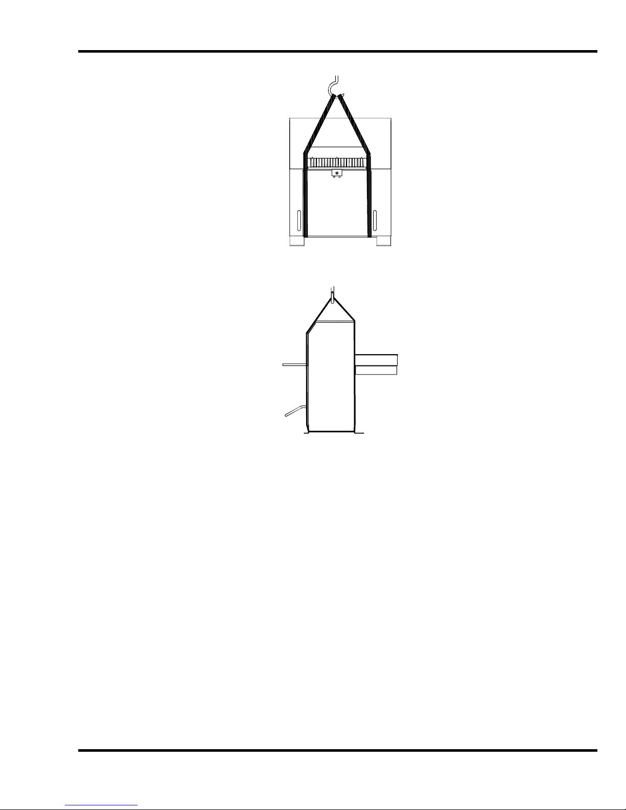
Alternately, the following method may be used to lif t t he machine from the skid. Remove the table
extensions (page 11) and the lower front cover. Using lifting straps rated at 2000 lbs. or more, wrap
the straps around the m ac hine base from front to back on each side of the tabl e as shown in Fi gure 2
& Figure 3. Hoist the machine and r em ov e its skid.
IMPORTANT! Do not lift the machine by any portion of the table. The aluminum table may pull
from the base and strip it s moun ting threads. Injury may result.
10
Page 11
5.0 Installati on & Setup
Figure 2
Figure 3
5.3 Cleaning
After unpacki ng, wipe down all machine panels and clean the table surface. The display screens and
control console should be c leaned using a mild water-based soap solution. DO NOT use petroleum
or oil based solvents as they wi ll damage the display screens and control consol e.
5.4 Fitting Throu gh N ar ro w Door
As shipped, the Tit an 265 c utt er will not fit through an opening less than 54” (137 cm). With the
extension tables removed, it will fit through a 46-1/2” (118 cm) opening. With the table and electric
eyes removed, it will fit through a 31” (79 cm) opening.
5.4.1 Removing the Extension Tables
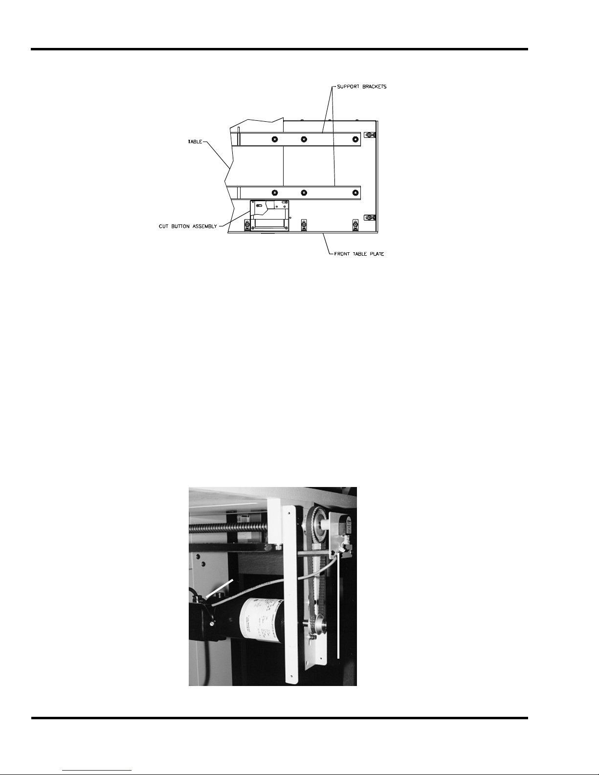
Make sure power is disconnect ed from the machine. Remove the f r ont t able plate (Figure 4) by
removing the hex nut s. Rem ov e the extension table hardware and remov e extensi on tables.
NOTE: There may be shims locat ed between the extension tables and the ext ensi on table brackets.
These are used for l ev eling the extension tables at the factor y . Take not e as to where they are
located so they c an be plac ed in the proper posi tion when reattaching the extension tables later.
11
Page 12
5.0 Installati on & Setup
g
Now remove the two extensi on table support brackets (Figure 4).
View from underneat h table
Figure 4
5.4.2 Removing the Table
Make sure the knife has been removed from the machine and that the knif e and clamp ar e in the “up”
position. If they are not , read the Power Hookup Section (page 17) to connec t power to the machine.
Turn on the power using the red and y ellow main power switch, and press the CLEAR butt on. This
will preset the back gauge and send the k nife and clamp up.
Turn off the machi ne and disconnect the power.
Make sure the extension tables have been removed (page 11). Remov e the 2-hand button controls.
Remove the sheet metal c ov er s fr om the r ear of the t able. Remove the backgauge motor cover, the
lower back panel, and the lower front cover of the machine.
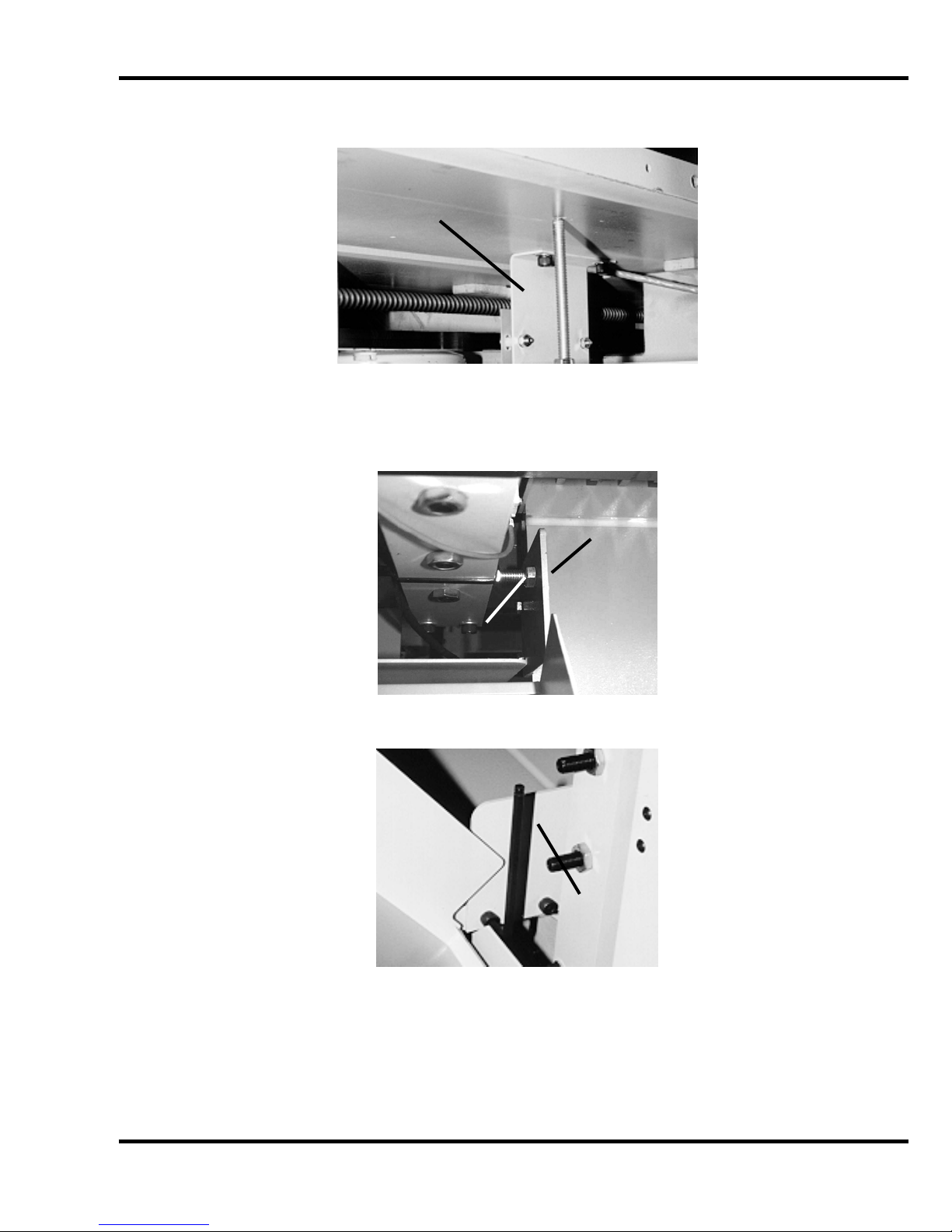
Unplug the cabl e to the encoder at t he bac k of the machine (Figure 5). Remove the motor juncti on
box cover and disconnect the wires to the motor (Figure 5). Rem ov e the leadscrew cover and the
nylon tyraps that ar e att ac hed to the bottom of the table. The motor wires and encoder wires shoul d
now be free from the tabl e.
12
Motor
Junction Box
Figure 5
Encoder
Plu
Page 13
5.0 Installati on & Setup
Remove the preset board assembly from the bottom of table (Figur e 6) .
Preset Board
Assembly
Figure 6
Open the top hood and loosen the jam nut on left hand side guide support screw and turn it in a few
turns for clearance, then remove the left and right si de guides as shown in Figure 7 & Figure 8.
Left Side
Guide
Side Guide
Support Screw
Figure 7
Right Side
Guide
Figure 8
Remove the two taper pins from the bottom side of the table by tightening the jam nut on the taper
pin. Then remove the f our screws that mount the table to the base. CAUTION: the table assembl y
is very heavy and requi res at least four people to remove. Pull the table out towards the back of
the machine.
13
Page 14

5.0 Installati on & Setup
5.4.3 Removing the Electric Eyes
Make sure power is disconnect ed from the machine. Open top cov er. Remove the four hex -head
screws for each el ectri c ey e assem bly from the inside of the machine. By slidi ng some of the sl ac k in
the cable through t he si de of t he m ac hine, t he ey e assem blies can be set on the machine. If it is
necessary to completely remove the eyes from the machine, the wires must be disconnected from t he
power panel.
5.4.4 Removing the Footswitch
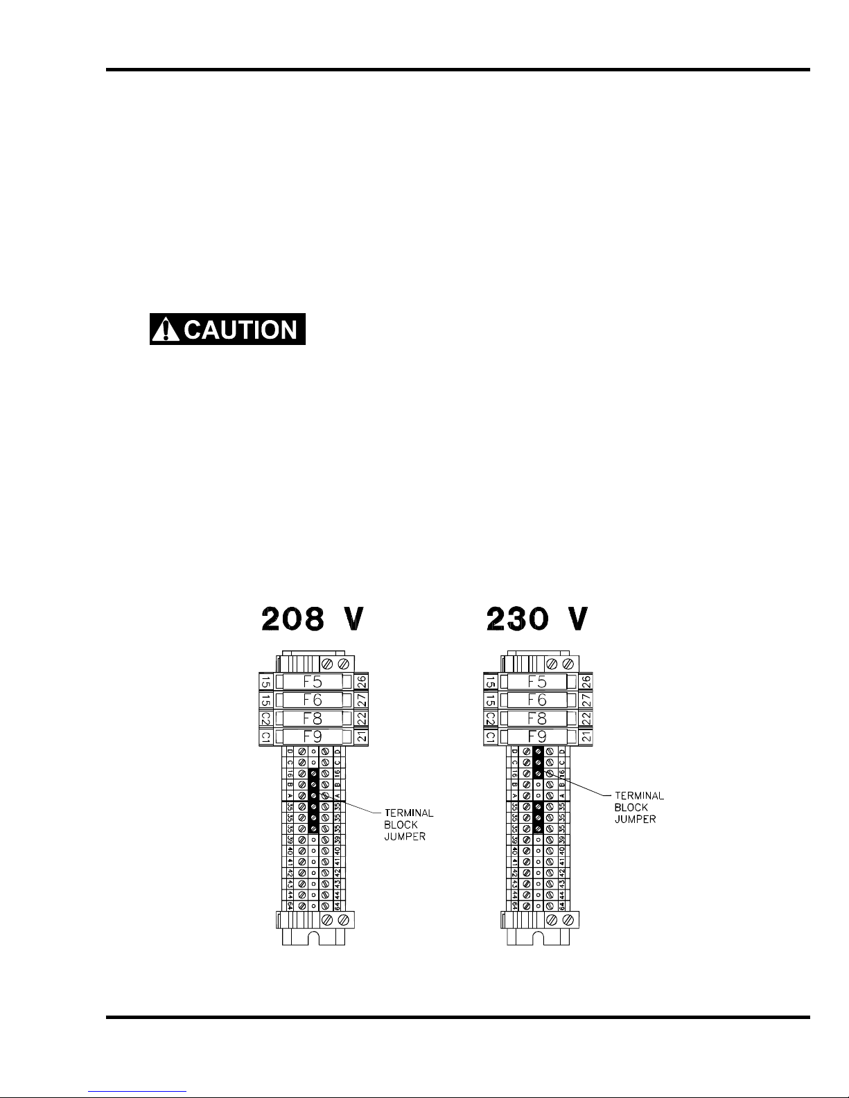
Make sure power is disconnect ed from the machine. Remove lower fr ont cover. Remove the two
screws that mount the f ootswitch bracket (Figure 9). Lay footswitch assembly inside t he m ac hine.
Mounting
Screws
Figure 9
5.4.5 Attaching the Table
Set the table in posi tion, and start its front two mounting screws. Then start the rear two mounti ng
screws. Replace the t wo taper pins (must be snug to seat the table), and then tighten all four screws.
Attach the right and left si de guides then re-adjust the left hand side guide support screw until it
contacts the side guide and tighten the jam nut. (Figure 7 & Figure 8 on page 13), the preset board
assembly (Figur e 6 on page 13) , t he m otor and enc oder wir e ( Figure 5 on page 12) and all guards
and panels.
Once the table is instal led, the backgauge squareness and accur ac y m ust be r eadjusted. See the
Titan 265 Technic al S ervice and Parts manual for information on how to do this.
5.4.6 Attaching the Extension Tables
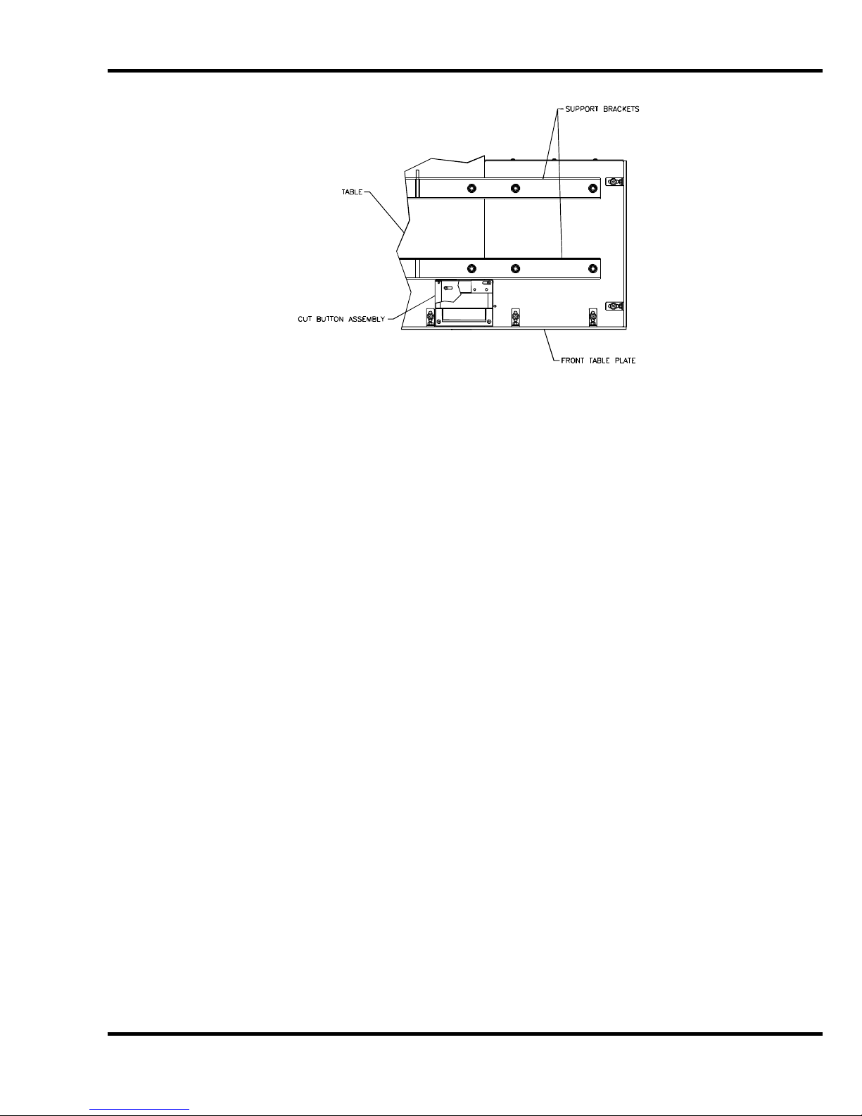
Attach the ext ensi on table support brackets to the under side of the main table as shown in Figure 10,
but do not tight en screws completely. Route each cut button wire thr ough the slots in the brackets
while attachi ng them. Next, place any shims that were instal led at the factory in the positi on they
were in when the extension tables were removed. Lay the table extensions in place and insert the
screws. Align the front edges of the tables and tighten screws. Attach the front table plate.
14
Page 15
5.0 Installati on & Setup
Figure 10
5.4.7 Attaching the Electric Eyes
Make sure power is disconnect ed from the machine. If necessary, connect the wires to the power
panel. Attac h electri c ey e assemblies with provided hardware, m aki ng sure that the bottom of the
electric ey e housings are paral lel to the table. Once power is hooked up, the electric eyes should be
checked for alignment. See the Titan 265 Technical Servic e and P arts manual for information on how
to do this.
5.4.8 Attaching the Footswitch
Make sure power is disconnect ed from the machine. Attach the foot switc h br acket using the
mounting hardware (F igure 9, page 14).
5.5 Hydraulic System Check
The Titan 265 is powered by a hydraul ic system consisting of an electric m otor c oupled directly to a
hydraulic pump.
The hydraulic r eservoir holds 5 gallons of hydraulic fluid. It is filled with Tellus #46 hydraul ic fluid at
the factor y but shoul d be c hec k ed before operation. Remove the lower rear panel c ov er. Check the
sight gauge on the rear si de of t he hy dr aulic tank. Fluid should just be vi si ble in the si ght gauge
(Figure 11, next page). Add fluid if necessary, but avoid overfilling. For more inform ation about
checking and changing the hydraulic fluid, including a cross-referenc e c har t of appr ov ed fluids, See
the Titan 265 Technical Service and Parts manual. When finished, replace the panel.
15
Page 16

5.0 Installati on & Setup
Sight
Gauge
Figure 11
The hydraulic fluid should be checked weekly and changed AT LEAST ONCE-PER-YEAR or after
every 1,000 hours of operation.
5.6 Optional Fals e Cl am p Plat e
To prevent marking on pressure sensitive jobs, a false clamp plate is availabl e as an optional item for
your machine. Thi s pl ate attac hes to the bottom of the clamp. It is secured with (3) setscrews
located in holes on the lower front face of the clamp.
To insta ll :
1. Make sure t he k nife and clamp are in the up position. If they are not , t ur n on the power using
the red and yellow mai n power swit c h. Press the CLEAR button. This will preset the
backgauge and send the knife and clamp up.
2. REMO V E KNIF E. See Section 7.1 Knife Removal, page 41.
3. Turn the power off and disconnect the power cord.
4. Sli de the false clamp plate under the cl am p and slide the plate up into position.
5. Hold the plate in position and secure with the (3) setscrews located in the lower f r ont f ace of
the clamp, Figure 12.
6. A sensor det ec ts that the false clamp is installed and the computer setting will automatically
be set to ON.
NOTE: The minimum cut with the false clamp plate attached is 1-7/8”.
False Clamp Plate Set Screws
16
Figure 12
Page 17
5.0 Installati on & Setup
5.7 Power Hook-Up (208/230V 50/60Hz)
For satisfact ory oper ation, be sure that your cutt er is wired for the correct phase and v ol tage and has
adequate power. The c orrect elect rical specifi cations for your machine are shown on the seri al plate.
Check the machine serial plate before connecting the power. For future reference, transfer this
information to the front cover of this manual.
Watch Setup Voltage- Inadequate power to the cutter can be a major source of problems. Too
many machines on the same circuit will reduce the power to each machi ne. Inadequate v oltage wil l
frequently cause overheating, loss of power, and in extreme cases, failure to operate. Test your
voltage when the shop is at actual working level s. Challenge recommends a dedi cated line wit h a
lockable di sconnect to provide adequate power f or this machine.
CAUTION: SHOCK HAZARD! Always disconnect power at main
power panel befo re working on the cutter. Lock it out to prevent accidental power up. (S ee
Power Loc kout Procedure page 5).
Important: You must have an adequ at e si ze ci rc uit and heavy enough wir ing for this mac hine. T he
circuit size should be a minimum of 20% greater than the amperage rating on the machine
nameplate. If a wire is run over 75 feet ( 23 meters), the next siz e wire should be used. Check local
electric al c odes.
Electrical Sp ecifications for the Titan 265:
Three Ph.: 208/230 V 25 A 30 A #10 AWG
Voltage Amperage Circuit Size Wire Size
Single Ph.: 208/230 V 30 A 40 A #8 AWG
Check incoming v oltage and positi on voltage selecti on jumper in proper loc ation as shown in (Figure
13).
Voltage Amperage Circuit Size Wire Size
Figure 13
17
Page 18

5.0 Installati on & Setup
NOTE: The terminal block jum per must be set t o the correct location according to the supply voltage
of the machine. Failure to set the t erminal block jumper will cause damage to the machi ne!
The power source is connect ed to the cutter at in the junction box loc ated at the rear , r ight hand side
of the machine.
5.7.1 Single Phase Hook-Up
1. Disconnec t the power at the main power panel and l ock it out to prevent accidental power-up.
See Power Lock-Out pr oc edur e, page 5.
2. Thread the power cord through the knock - out hole in the junction box located near the fl oor in
the lower left hand c or ner of t he machine rear. Secure it with a conduit connector.
3. Fasten the ground lead to the ground terminal lug found in the junction box.
4. Use wire nuts to join the two power leads to the L1 and L2 leads found in the junction box.
5. Close al l doors and guards, unlock the main power and swit c h it on. The machine should
now have power.
5.7.2 Three Phase Hook-Up
1. Disconnec t the power at the main power panel and l ock it out to prevent accidental power-up.
See Power Lock-Out pr oc edur e, page 5.
2. Thread the power cord through the knock - out hole in the junction box located near the fl oor in
the lower left hand c or ner of t he machine rear. Secure it with a conduit connector.
3. Fasten the ground lead to the ground terminal lug found in the junction box.
4. Use wire nuts to join the three power leads to the L1, L2 and L3 leads found in the junction
box.
5. Close al l doors and guards, unlock the main power and swit c h it on. The machine should
now have power.
6. Press both cut buttons simultaneously to activate the motor and check to make sure it is
turning the same dir ec tion as the arrow on the motor casing. If it isn’t, disconnec t the power
and simply exc hange any two leads of the power cord as in Figure 14 on page 18. The motor
will now turn the corr ec t direc tion. Double check to make sure.
1
31 2
2
18
Figure 14
3
Page 19
5.0 Installati on & Setup
5.8 Power Hook-Up (380/400/415V 50Hz) – also applies for (460V
60Hz)
For satisfact ory oper ation, be sure that your cutt er is wired for the correct phase and v ol tage and has
adequate power. The c orrect elect rical specifi cations for your machine are shown on the seri al plate.
Check the machine serial plate before connecting the power. For future reference, transfer this
information to the front cover of this manual.
Watch Setup Voltage- Inadequate power to the cutter can be a major source of problems. Too
many machines on the same circuit will reduce the power to each machi ne. Inadequate v oltage wil l
frequently cause overheating, loss of power, and in extreme cases, failure to operate. Test your
voltage when the shop is at actual working level s. Challenge recommends a dedi cated line wit h a
lockable di sconnect to provide adequate power f or this machine.
CAUTION: SHOCK HAZARD! Always disconnect power at main
power panel befo re working on the cutter. Lock it out to prevent accidental power up. (S ee
Power Loc kout Procedure page 5).
Important: You must have an adequ at e si ze ci rc uit and heavy enough wir ing for this mac hine. T he
circuit size should be a minimum of 20% greater than the amperage rating on the machine
nameplate. If a wire is run over 75 feet ( 23 meters), the next siz e wire should be used. Check local
electric al c odes.
Electrical Sp ecifications for the Titan 265:
Three Ph.: 380/400/415V 50Hz 15 A 30 A #10 AWG
460V 60Hz 11.5A 25 A #10 AWG
Check the incoming voltage – if it is different from the factory set 415V, the tap on the main
transformer must be changed to match the incoming voltage - see Figure 15, page 20, for the
procedure.
The following also appl ies for 460V 60Hz Hook-ups – use taps H4 and H1.
Voltage Amperage Circuit Size Wire Size
Figure 15
19
Page 20

5.0 Installati on & Setup
The power source is connect ed to the cutter at in the junction box loc ated at the rear , r ight hand side
of the machine. The power i s then r un up to t he m ai n transformer mounted to the side of the machine,
under the top hood.
5.8.1 Three Phase Hook-Up
1. Disconnec t the power at the main power panel and l ock it out to prevent accidental power-up.
See Power Lock-Out pr oc edur e, page 5.
2. Thread the power cord through the knock - out hole in the junction box located near the fl oor in
the lower left hand c or ner of t he machine rear. Secure it with a conduit connector.
3. Fasten the ground lead to the ground terminal lug found in the junction box.
4. Use wire nuts to join the three power leads to the L1, L2 and L3 leads found in the junction
box.
5. Close al l doors and guards, unlock the main power and swit c h it on. The machine should
now have power.
6. Press both cut buttons simultaneously to activate the motor and check to make sure it is
turning the same dir ec tion as the arrow on the motor casing. If it isn’t, disconnec t the power
and simply exc hange any two leads of the power cord as in Figure 14 on page 20. The motor
will now turn the corr ec t direc tion. Double check to make sure.
1
2
31 2
3
Figure 15
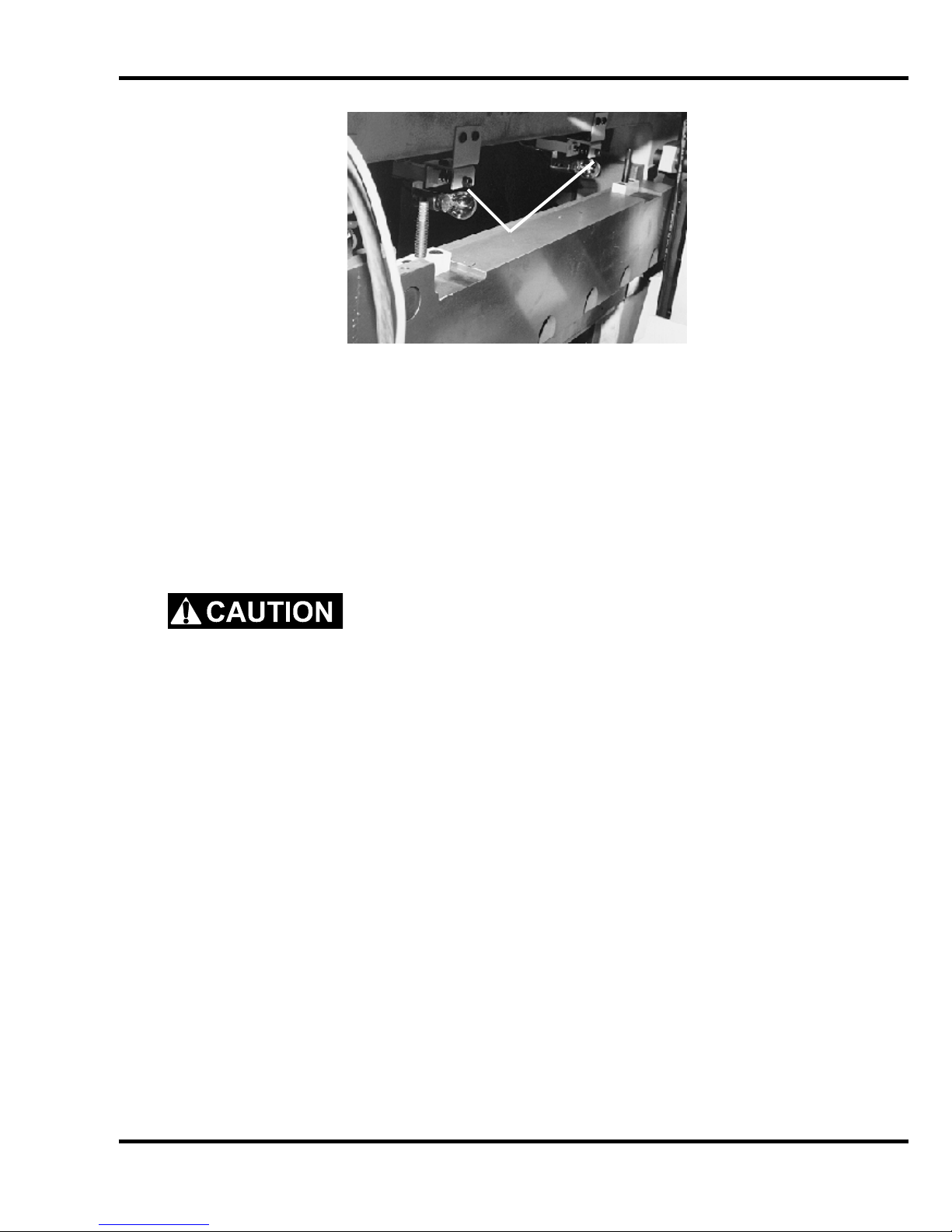
5.9 Line Light
The Titan 265 is equipped with two lights, which provide a line of li ght on the paper in the
approxim ate loc ation of where the paper will be cut. The lights come on when power to the machine
is turned on. The light from eac h bulb r eac hes t he table after passing between the knife and cl amp.
Each light is foc used with a socket head cap screw (Figure 16).
20
Page 21
5.0 Installati on & Setup
Line Light
Adj. Screws
Figure 16
To Adjust:
1. Pl ac e a wi de sheet of paper on the cut stick to view the line light.
2. Using a 3/16” hex allen wrench, turn one of the cap screws until you see a 1/16-1/8” beam.
NOTE: it is best to start by turning the screw clockwise. If the screw turns all the way in
before a line appears, begin turning the screw counterclockwise.
3. Similarly, turn the adjustment screw of the other bulb, until one c ontinuous beam is seen
across the cut stick.
SHOCK HAZARD! Always disconnect power at main power panel
before working on the cutt er. Lock it out to prevent accidental power up. See Power Lo ckou t
Procedure, page 5.
Bulb repl acement:
1. Make sure power is off (see Power Lockout Proc edur e, page 5).
2. Rem ov e the old bulb by lightly pushing the bulb into the socket and turning it 1/4 turn
countercl oc k wise. CAUTION! If the bulb is still hot, allow a few minutes for it to cool.
3. Insert the new bulb into the socket, push it in and twist it clockwise until the bulb lock s i nto
place.
4. Reconnect power and t ur n the main power switch on. Readjust the line if necessary.
21
Page 22
6.0 Operation
)
) Job
epeat
6.0 Operation
IMPORTANT: DO NOT ATTEMPT TO OPERATE THE CUTTER UNTIL YOU HAVE THOROUGHLY
READ AND UNDERSTAND ALL OF THE FOLLOWING INSTRUCTIO NS. CALL YOUR
AUTHORIZED CHALLENGE DEALER IF YOU STILL HAVE ANY QUESTIONS.
6.1 Power - Main Power Switch
Figure 17
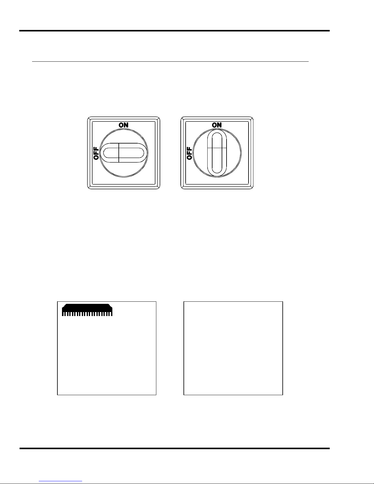
Power is brought to the m ac hine when the main power switch is turned to t he “ON” position (Figure
17). The display and line lights are turned on at this time.
The screen saver will activate and the line lights will shut off after 5 minutes without any activit y. This
shut-off time c an be changed i n the Par am eters screen of the Maintenance Mode (see the “ Operating
Controls/Maintenance Mode/Paramet er s/Time Out” section). To restore power to the displ ay and line
lights, press any button on the keyboard.
6.2 Start Up
Once power has been turned on, the display will show the following:
When the CLEAR key is pressed, the bac k gauge will move to coordinate t he true posi tion into the
computer (if the knife and clamp are not in the “up” position, the displ ay will pr om pt the operator to
raise them by pressing t he c ut but tons prior to presetting the bac k gauge) . When finished, the
machine will be i n “Send Mode” and the display will appear similar to the displ ay shown next :
Clamp
Pressure
| | | 14 | | |
------------------------------ C) Up
D
Down
55.000 in
>_
Backgauge must move to be
preset. Please clear the table.
Revision 1.0
Press clear to start
E) Maint
F
H) R
22
Page 23

6.0 Operation
The backgauge may now be sent to a desired posi tion by simply typing the dimension and pressing
SEND (see the “Send Mode” secti on, page 28, for more details).
Clamp
Pressure
| | | 14 | | |
------------------------------ C) Up
D) Down
5.070 in
>_
E) Maint
F) Job H) Repeat
6.3 Making a Cut
Place the paper agai nst the backgauge and left side guide. Note: if the c ut will leave strips of paper
less than 2-1/8” wide, place the paper against the right side gui de. This will prevent the strips fr om
getting caught in the small opening near the left side guide.
First, start the hydr aulic motor by simultaneously pr essing bot h cut buttons (located under the t able at
the front of the machine) . Then, with the electric eyes unobstruc ted, make a cut by simultaneously
pressing both buttons and holding them in until the knife reaches the table. If at any time during the
cut cycle one or both cut but tons are released, or if the elect ri c ey es are obstructed, the knife and
clamp will immediately be sent to the up position. Once the cut cy cl e is complete, the hydraulic motor
will continue t o r un until the time out period expires, or it c an be shut off by pr essing soft-key “B”
(Motor Off) or by pressing and hol ding the right cut button for three seconds.
6.4 Air Table Option
Machines equipped wit h an air table option can have the air table feature turned on or off by pressing
soft-key “D” (Air) or by pressing and holding the left c ut button for three seconds.
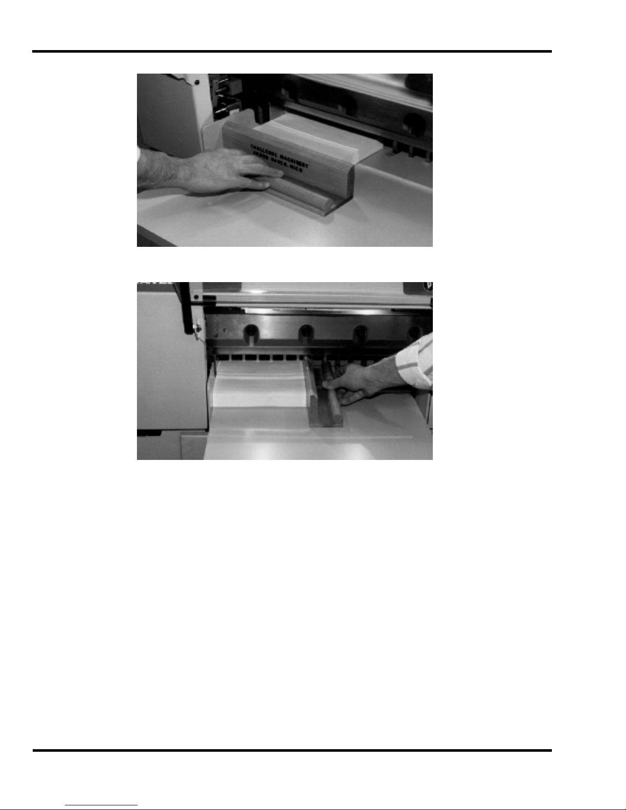
6.5 Jogging Aid
Always remove the joggi ng aid from the table before making a cut.
A jogging aid is included as standard equipment with t he Titan 265. This tool allows the operator to
load and align paper without the need to place hands or arms under the knif e or clam p.
To use, load the paper agai nst the side and backgauge using the joggi ng aid (Figure 18 & Figure 19).
Remove the jogging aid from the table and make the cut.
23
Page 24
6.0 Operation
Figure 18
Figure 19
6.6 Adjusting the Clam p Pr ess ur e
The clamp pressure can be adjusted by pr es sing soft-key “C” (Up) to inc r ease the pr essure, and softkey “D” (Down) to decrease the pr essure. The pressure scale ranges fr om 0 to 15, 15 being t he
maximum.
6.7 Pre-Clam pin g
The Titan 265 is equipped with a low-pressure clamping feat ur e, which allows the operator to cl am p
paper under low pressure bef or e beginning the cut cycle. To use this feature, press down on the foot
switch loc ated at the front of t he m achine until the clamp comes down on the paper. To raise the
clamp, rel ease the foot switch. To make a cut, keep the foot switch pressed and press the c ut
buttons. Release the foot switch once the cut has been complet ed. Avoi d placi ng hands under t he
clamp.
24
Page 25
6.0 Operation
6.8 Knife Change Alarm and Lubrication Alarm
The Titan 265 XG has two built in alarms that will be displayed after a certain number of cuts. The
knife alarm di spl ay s a message to remind the operator to change the knif e. The lube al arm displays
a message to remind the operator to have the machine lubricated. The lube alarm will also display
the name and phone number of the Chall enge dealer from which the machine was purchased. To
reset either alarm, or to change the knife alarm val ue, see the “Operating Controls/Maintenance
Mode/Paramet er s/ K nife Count” section on page 31 . The lube alarm value is fact or y set at 2,500
cuts and cannot be changed.
NOTE: The alarms do not prevent norm al oper ation; they are simply remi nder s.
6.9 Electric Eyes
The electric ey es prevent reaching into the cutti ng ar ea while a c ut is being m ade. If the beams are
broken while a cut i s bei ng made, the knife and clamp will return to the up posi tion.
6.10 False Clamp Plate
The false clamp plate is an optional attachment, whic h reduces the cr easi ng of paper caused by the
clamp. The disadv antage of using the false clamp plate is that it limi ts the smallest cut dimension.
The machine has a built-i n sensor that detects when the fal se clamp plate is installed, and the
computer will automatically restrict the backgauge position accordingly.
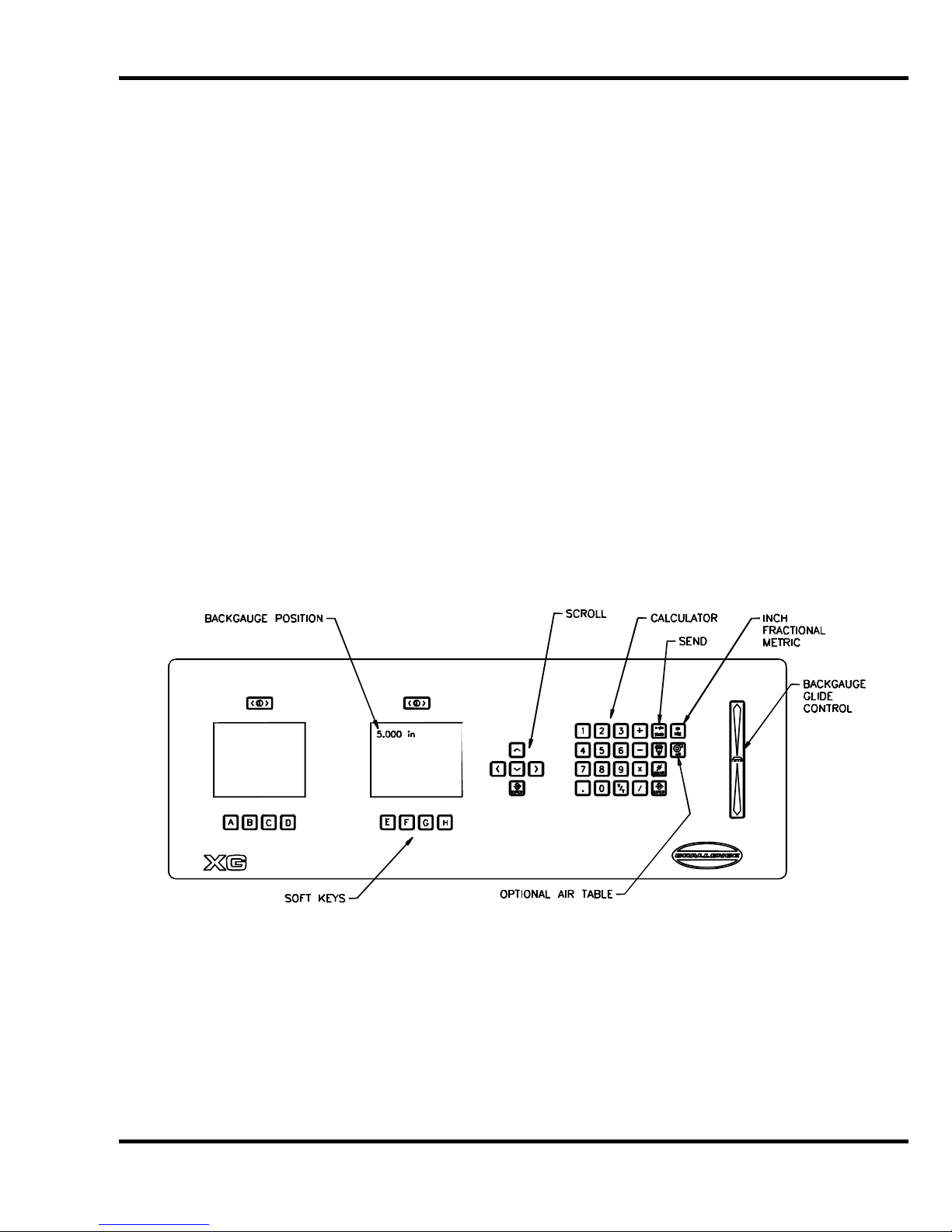
6.11 Display Panel
6.12 Definiti on of Ke ys
6.12.1 Backgauge Glide Control
The backgauge glide c ontrol is used to manually position the backgauge. The speed of the
backgauge will depend upon where the ac tuator is pressed. Press farther from center for a faster
speed, and closer t o c enter for a slower speed. To move the backgauge forward, press down ward.
To move the backgauge backward, pr es s up ward.
25
Page 26

6.0 Operation
6.12.2 IN/MM Key
This key toggles the display to show the position and programmed send values in inches (e.g. 5.250),
inch fractions to the nearest 1/64” (e.g. 5_
1
/4), or millimeters (e.g. 133. 3) .
6.12.3 Air Table ON/OFF Key
This key turns the ai r table on and off.
6.12.4 Send Key
The SEND key is used to send the backgauge to any valid position. If an att em pt is made to send the
backgauge to an illegal position, an error message will be displ ay ed at the bottom of the screen
stating “Number outside limit”. In the Job mode, the SEND key will also adv anc e the back gauge to
the next sequenti al c ut position before performing the cut.
6.12.5 Push-Out Key
The push-out key will m ov e the back gauge forward 5 inches (or to the most forward position) and
then return it to its previous position. This allows paper to be removed from the cutter without putting
hands under the knife and clamp.
the backgauge glide control to move the paper to an area where it can be r eac hed.
Never place hands in the clam p and knife ar ea. Use the push-out key or
6.12.6 Clear Key
The CLEAR key is used to clear err or messages and t he c ur r ent entry line.
26
Page 27

6.0 Operation
6.12.7 Enter Key
The ENTER key selects items in several modes and processes data that has been entered in the
other modes.
6.12.8 Priority Add (X/Y) Key
The priority/add key is used for entering fractions when they are combined with whole num ber s. The
symbol display ed when this key is pressed is the underli ne symbol “ _”. An exam ple of a number
entered using the priority/add key is 1_1/2.
6.12.9 Soft Keys
There are a total of eight Soft Keys labeled “A” through “H”. The func tions of these keys change
depending on the operating mode. The function of each key c an be found on the bottom of the
display screens.
6.12.10 Arrow Keys
The four arrow keys can be used in almost all screens. The arrow keys are prim aril y used for moving
the cursor around on the screen, or to toggle between highlighted selections. In some screens, the
left arrow key act s as a backspace key.
6.12.11 Contrast Control (Only on Serial numbers 101876 and below)
The contrast of each display screen can be adjusted by using the c ontrast control buttons located
directly abov e eac h displ ay screen.
6.12.12 Contrast Control (For Serial numbers 101877 and Above)
The contrast of each display is controlled by the comput er if additional adjustments are needed use
the following procedures;
A. To adjust the left hand screen ( Graphic screen) hold the hidden button (located to the
right of the “CLEAR” butt on and below the “AIR” button) and use the ri ght and left scroll
buttons to adjust the contrast.
B. To adjust the ri ght hand screen (Text screen) hold the hidden but ton (located to the right
of the “CLEAR” button and below the “AIR” button) and use the up and down scroll
buttons to adjust the contrast.
27
Page 28

6.0 Operation
6.13 Manual Backgauge Control
6.13.1 Backgauge Glide Control
The backgauge can be moved m anually by use of the backgauge glide control . Pr ess towards the
operator for forward travel and away from the operator for reverse travel. The further away fr om
center that the actuator is pushed, the faster the back gauge will trave l.
6.13.2 Backgauge Control Knob
The backgauge may also be contr olled using the Backgauge Control Knob l oc ated at the front of the
table. Turning the knob cl oc k wise brings the backgauge forward. Tur ning the knob counterclockwise sends the backgauge bac kward. The further the knob is tur ned, the faster the backgauge
will travel.
6.13.3 Backlash Indicator
To insure accurate cuts, the backgauge must be brought to the cut position from the rear of the table.
In the display, to t he ri ght of the bac k gauge posi tion, there is a small arrow to indicate reverse travel.
This arrow should be off when m aki ng a c ut. Moving back past your cut positi on, then forward to it,
compensates f or any pl ay i n the back gauge nut and lead screw.
6.14 Send Mode
Clamp
Pressure
| | | 14 | | |
------------------------------ C) Up
D) Down
The send mode is the first screen displayed after the backgauge is preset. From this screen the
backgauge can be positioned with the backgauge pi npoint control or by entering a value and pr essing
the SEND key. A mathematical expression can also be entered as a send value. Simply type t he
expression and press SEND. Y ou c an also enter an equation which begins with the current
backgauge posit ion. For example, if you want to send the backgauge 2” forward from its current
position, just pr ess [-] [2] and SEND.
The send mode screen can al so be used f or doi ng m ath cal c ulations that are larger than the
backgauge’s rev er se l im it. In this case, you must press ENTER to have the result displayed on the
screen.
5.070 in^
>_
E) Maint
F) Job H) Repeat
Reverse
Indicator
Arrow
28
Page 29

6.0 Operation
6.14.1 Entering Math
In the simple send mode, the Titan 265 XG is capable of calculating an entire math string such as,
10-5+5x6+2_3/ 4. However, the result is limited to 29999.000 and t he r esul t cannot be a negative
value. In the job mode, and duri ng a send, the result of the calculation must be less than the
backgauge limit of 30. 500 inches.
6.14.2 Entering Fractions
Fractions are enter ed with the priority add key X/Y. T he symbol displayed when this key is pressed is
the underli ne sym bol “ _”. This instructs the computer to add the fr actional portion of the entry bef or e
performi ng the rem aining math. This key is useful when entering a formula as follows: 3x2_3/4 =
8_1/4. If a simple plus had been used instead, the result would be as f ollows: 3x 2+3/4 = 6_3/4.
6.15 Repeat Mo de
This mode allows the operator to make a series of cuts during which the back gauge m oves a
specified distanc e between each cut. To enter repeat mode, press sof t-key “H” (Repeat). The
display will then look like the one next:
Clamp
Pressure
| | | 14 | | |
------------------------------ C) Up
D) Down
Type in the desired initial backgauge position and pr ess ENTER. The backgauge will then move to
that position. Then type in the step value and press ENTER. Positi on the paper and m ak e a c ut.
The backgauge will then move forward by the step amount, and a new cut can be made. When
finished, press sof t-key “H” (Exit) to exit bac k to send mode.
5.070 in
ORIGIN >_
STEP
Initial Position
H) Exit
29
Page 30

6.0 Operation
6.16 Mainten an c e Mo de
The maintenance mode is an area where many machine functions can be set or m odified. The four
principl e functions are: Language, Parameter s, Di agnostic, and Knife Adjust. To select a par ticular
function, use the up and down arrow keys to toggle to the desired function and press ENTER. See
the following descriptions for an explanation of each function.
Clamp
Pressure
| | | 14 | | |
------------------------------ C) Up
D) Down
5.070 in
MAINT MENU
LANGUAGE
PARAMETERS
DIAGNOSTICS
KNIFE ADJUST
Select and press enter
G) Send
F) Job H) Exit
6.16.1 Language
In the language screen, use the up and down arrow keys to toggle to the desired language, and press
ENTER. All messages will be displayed in the selected language.
6.16.2 Parameters
In the paramet er screen, use the up and down arrow keys to toggle to the desired par am eter, and
press ENTER. See the descriptions that follow for an explanat ion of each parameter.
6.16.2.1 False Clamp
The Titan 265 has a sensor that determines when the false clam p plate is installed. This parameter
shows whether the false clamp is installed or not.
6.16.2.2 Time-out
This parameter sets the am ount of idle time for which the screen saver ac tivates and the line lights
and hydraulic motor turn off. The choices are 2, 5, 10, 20, and 30 minutes. I n the time-out screen,
use the up and down arrow keys to toggle to the desired time-out, and press ENTER.
6.16.2.3 Push-out
Normally, whenever the backgauge is sent to a larger dim ensi on, a five-inch (127mm) push-out is
perform ed to aid t he operator in ac c essing the paper. In some situations, it m ay be necessary to turn
this featur e off . It is recommended that this feature be left on whenev er possible. In the push-out
screen, use the up and down arrow keys to t oggle to the on or off status as desired, and press
ENTER.
6.16.2.4 Accuracy Adjust
This parameter pr ov ides a means for adjusting the accuracy of the back gauge. To change the
accuracy, send the bac k gauge to 2 inches (50.8mm) and cut some paper . Measure the paper, and
30
Page 31

6.0 Operation
type in what you actually measure. The computer will calculate the amount of error and will
compensate. A value may al so be added to or subtr acted from the current value.
6.16.2.5 Knife Count
The knife count parameter allows the operator to reset the knife alarm and the lube alarm. The knife
alarm displays a message to r em ind the operator to change the knife. The lube alarm displays a
message to remind the operator to have the machine lubricated. The lube alarm will also display t he
name and phone number of the Challenge dealer from which the machine was purchased.
There are three functions within the knife count par am eter: Clear Count, Knife Alarm, and Clear
Lube. Select the desired function and press ENTER. See the following descri ptions for an
explanati on of eac h function.
Select Clear count to reset the knife c ounter when a knife change has been performed.
Select Knife Alarm to enter or change the knife stroke alarm value. When this value is reac hed, the
display will aler t you to change the knife and reset the knife count er. Knife alarm values for the Titan
265 XG are factory set at 2,500 cuts. However, you may want to change thi s value based on your
specific machine applications. See the Knife section for help in choosing a knife alarm value f or your
machine.
Select Clear lube to reset the lube alarm after performing the lubrication requirements as shown in
the Lubrication section of this manual. NOTE: The alarm will activ ate after 2,500 cuts. This value is
set at the factory and cannot be c hanged.
6.16.2.6 Machine count
The number displ ay ed is the total number of cuts made by the machine.
6.16.3 Diagnostic
The diagnosti c ar ea can be very hel pful in locating a problem in the ev ent of a machine m alfunction.
Use the up and down arrow keys to toggle to the desired selection, and press ENTER. See the
following descri ptions for an explanation of eac h.
Clamp
Pressure
| | | 14 | | |
------------------------------ C) Up
D) Down
5.070 in
DIAGNOSTIC
Error Code
Sensor Data
Clear Memory
Adjust Clamp
Select and press enter
A) Maint G) Send
F) Job H) Exit
31
Page 32
6.0 Operation
6.16.3.1 Error Code
The Error Code functi on simply recalls the last five err or messages that were di spl ay ed. This can be
very useful in cases when the malfunction cannot be reproduced i n the presence of the service
technician.
6.16.3.2 Sensor Data
The Sensor Data function provides a list of computer inputs and output s (proximity switches, etc.)
along with their status (0 for open, 1 for closed). This functi on allows a service technician to chec k
the status of a switch without removing any covers. Cuts and backgauge movements are allowed in
this screen so that the technician may observe the status of the inputs and outputs during machine
operation.
6.16.3.3 Clear Memory
The Clear Memory function resets the memory to a known state. All cut po sitio ns will be erased
during this operation.
6.16.3.4 Knife Adjust
The knife adjust function provides a way for the service technician to change the knife. In the Knife
Adjust screen, use the up and down arro w keys to toggle to the up or down status as desired, and
press ENTER. Press and hold the cut but tons to send the knife to the desired position.
6.17 Job Mode
Clamp
Pressure
| | | 14 | | |
------------------------------ C) Up
D) Down
>
JOB 1
1>
2>TESTJOB
5>
6>BOBS JOB Lock
7> 8.5 X 11 Lock
9>
10>
+
E) Lock G) Erase
F) Copy H) Exit
The Titan 265 XG can be programm ed for up to 99 different jobs. A job is a sequence of
programmed c ut positions. The backgauge moves to each position after a cut cycle is made. Each
job can hold up to 99 send val ues. Job mode is entered by pressing soft-key “F”. W hen the job m ode
is entered, all previously programmed jobs will be displayed along with their name and lock status.
Locked jobs display the word “Lock” after their name. A plus “+” sign at the bott om of t he scr een
indicates there ar e m or e jobs programmed than what are displayed. Pressing the left arrow key and
the down arrow key sim ultaneously will page down to the next set of jobs. P age 59 contains an
example of how to program a job.
32
Page 33
6.0 Operation
6.17.1 Lock/Unlocking a Job
In the Job Mode screen, the soft-key “E” will display “Lock” or “ Unlock” depending on the current
status of the job. If a job is locked, the word “Lock” will be displayed t o the ri ght of the job name.
Locking a job prevents it from being edited. To change the lock stat us of a job, sim ply move the
cursor to the desired job using the up and down arrow keys, and press the soft-key “E” (Lock/Unlock) .
6.17.2 Copying a Job
First, select a job to copy by moving the cursor up or down to the desired job number and pr ess the
soft-key “F ” (Copy) . “S elec t Copy to #” will be displayed at the bottom of the screen. Enter a job
number for the new job or move the cur sor to an existing job and press ENTER. If the new job is
locked, the copy will not be allowed. NOTE: if the new job is not locked, but contains data, the old
data WILL BE LOST.
6.17.3 Erasing a Job
Select a job to erase by mov ing the cur sor to the desired job. Press the soft- k ey “G” (Erase). “Clear
channel #” will be displayed, followed by YES or NO. Use the up and down arrow keys to toggl e to
YES or NO. YES will erase the job, NO will leave the job unchanged. NOTE: locked jobs cannot be
erased.
6.17.4 Creating a New Job
To create a new job, type i n a number t hat is not alr eady assigned t o a job and press ENTER
(entering a job num ber gr eater than 99 will create job #99). The cursor will move to the line
corresponding to t he num ber y ou typed in, prompting you for a job name. If no job name is desir ed,
simply press ENTER again to begin entering send values (see bel ow). To name the job, press the
right arr ow key to move the cur sor to the first character position. Enter a character of the alphabet by
using the up and down arrow keys to toggle to the desired character. The numeri c keys can be used
to enter numbers di r ectly into the job name. When the desired character i s in pl ace, use the right
arrow key to move to the next char ac ter position. The job name can be up to 10 characters l ong. A
letter can be rem ov ed from the job nam e by mov ing the cursor to the undesired character and
pressing the CLEAR k ey. When fi nished, press ENTER to save the name and to begin enteri ng send
values. The screen should now look similar to the one below:
Clamp
Pressure
| | | 14 | | |
------------------------------A) Division
D) Cut & Rec.
6.17.4.1 Entering Send Value
5.070 in JOB1
#1
1>_
E) Insert G) Erase
F) Job H) Exit
Send values can now be entered by using any of the following methods: 1) Type i n the desir ed v alue
and press ENTER, 2) Press ENTER at a blank line - this will enter the current position of the
33
Page 34
6.0 Operation
backgauge as a send val ue, 3) Use the “ Cut and Recor d” feature (described later) or 4) Use the
“Sheet Divi si on” feat ur e.
6.17.4.2 Creating a Stock Loading Position
After typing a send v alue, pressing the right arrow key instead of E NTER will m ov e the cur sor t o the
right and prom pt t he operator to enter a rotation indicator mar k or Load Zone ( LZ). Selecting LZ will
make it impossible to cut at that position. Pressing both cut butt ons on a posit ion marked at a
Loading Zone will pr om pt t he bac k guage to move to the next position in the job. Using a loadi ng
position eliminates the need to reach into the knife/clamp area of the cutter when loading a job.
6.17.4.3 Entering Rotation Mark
After typing in a send value, pressing the right arr ow key instead of ENTER will move the cursor t o
the right and prompt t he oper ator to enter a rotation indicat or mark . The di splay will look similar to the
one shown next:
Use Soft Keys “C” and “D” to choose a tur n indic ator. Pressing ENTER will place an indicator mark to
the right of the send v alue, as shown below:
When the desired indicator mark is in place, press the ri ght arrow key. The cursor will move to the
right and prom pt t he operator to enter a clamp pressure (see the following section).
NOTE: All new entry lines will have the same turn indicator mark as the one abov e it, until it is
changed.
Turn Indicator
Off
ccw >
cw <
180 Turn >>
Load Zone LZ
Select & Press Enter
C) Up
D) Down
Clamp
Pressure
| | | 14 | | |
------------------------------ C) Up
D) Down
5.070 in JOB1
#1
1> 5.070 _
H) Exit
5.070 in JOB1
#1
1> 5.070 >>
H) Exit
34
Page 35
6.0 Operation
6.17.4.4 Entering the Clamp Pressure
A separate clamp pr essure can be enter ed for each cut in a job. To enter the desired cl amp
pressure, fi r st enter the desired send value (descri bed abov e) , then press the right arrow key and
enter the rot ation mark if necessary (described above), then press the right arrow key agai n to mov e
the cursor to where the clamp pressure can be entered. Use Soft Keys “C” and “ D” t o inc r ease or
decrease the clamp pr essure, or use the numeric keypad to enter a num ber fr om 0 to 15 (see
Adjusting the Clamp Pressure section, page 24 for inf ormation about the clamp pressure setti ng) .
This will com plete the entry for the current line and move the cursor t o the send v alue of the next line.
NOTE: All new entry lines will have the same clamp pressure as the one above it, until it is changed.
6.17.4.5 Cut and Record
To use this featur e when creat ing a new job, simply send the backgauge to a desi r ed posi tion using
the backgauge glide control or by using SEND, then make a cut. The current bac k gauge posi tion will
automatically be displayed in the next avail able c ut location and the operator will be prom pted to
press ENTER to record t he c urrent v alue. If ENTER is not pressed, the value will not be recorded
into the job as a send value. Thi s can be ver y conv enient for setting up a program when the actual
cut positions are not k nown.
6.17.4.6 Sheet Division Feature
The Titan 265 XG has a sheet divi si on feature that automatically creat es a complete set of send
values using the parent and finished sheet sizes specified by the user. Since this feature creates an
entire set of send values, it is best to use it only when creati ng a new job. However , this feature can
also be used when editing or usi ng an exi sting job. It will simply insert the new set of send v alues
after the current send value.
Begin by pressing sof t-key “A” (Division). The display will be similar to the following:
------------------------------ C) Up
D) Down
5.070 in #1
DIM A>_
DIM B
DIM C
DIM D
Enter Dimension A.
E) Maint
F) Job H) Repeat
35
Page 36
6.0 Operation
The program gui des the oper ator through the steps of entering t he nec essary dimensions. Then the
program asks if the c olum ns are t o be cut separate (as opposed to stacking t he col um ns and cutting
them all at once). Press “1” f or Yes and “0” f or No. The display will now look similar to the one
shown on the next page (it may v ary based on the input).
Use the up and down arrow keys to scroll through the possible l ay outs. The l eft di splay will show
each choice visually. Select the desired option and pres s ENT E R. The send values will be
automatically calculated and entered. T he job will be complete and ready for use. To make changes,
edit the job as described i n the “Editing a Job” section below.
6.17.4.7 Label Cutting
------------------------------ C) Up
D) Down
5.070
QTY QTY
OPT OUT CUTS
1 8 9
2 8 9
3 8 9
4 6 7
5 8 9
6 6 7
RE-ENTER
H) Exit
A label cutting f eature is also provided on the Titan 265 XG. After pr ov iding the label quantity, si z e,
and gutter, the mac hine will automatically creat e a pr ogrammed job. Begin by entering the job mode,
select a job number and name ( optional) then depress ENTER. Depress the sof t-key “C” (Label)
under the left hand displ ay . The display will be similar to the following:
A
5.070 in #1
*Label Cutting*
QTY A>_
QTY B
DIM C
DIM D
DIM E
DIM F
Enter Quantity A.
E) Maint
F) Job H) Repeat
36
Page 37
6.0 Operation
The program gui des the oper ator through the steps of entering t he nec essary i nformation. A & B are
label quantities, C & D are the actual label size and E & F are gutter dimensions. Then the program
asks if the columns are to be c ut separate ( as oppo sed to stacking the columns and cutting them all
at once). Press “1” for Yes and “0” for No. The display will now look similar to the one shown on the
next page (it will var y based on the input).
5.070
QTY QTY
OPT OUT CUTS
1 8 9
RE-ENTER (0)
Select and Press Enter
H) Exit
Use the up and down arrow keys to scroll through the possible options (if m or e than one). The left
display will show each choic e v isually. Select the desired option, then press ENTER. At this point
the send values will be automatically calculat ed and entered. The job will be complete and ready for
use. To make changes, edit the job as described in the “Editing a Job” section below.
6.17.4.8 When Finished
When finished enter ing send values you may exit the current j ob by pressing sof t-key “B” (Job) to go
back to the job mode screen or sof t-key “D” (Exit) to exit to send mode. Or you may use the curr ent
job for cutti ng by pressing the down arrow at the last line and following the instructi ons i n the
“Running a Job” section (page 38).
6.17.5 Editing an Existing Job
6.17.5.1 Editing the Job Name
The job name can be edited (or added if an existing job does not have a name) in the job mode
screen. To edit the name, move t he cursor down to the desi r ed job number by pressing the down
arrow key. Then press the ri ght arrow key to move the cursor to the desired char ac ter position and
edit the character by pressing the up or down arrow keys to toggl e between characters of the
alphabet. Numbers can be entered directly by using the number keys. Pressing CLEAR clears the
current charac ter. When finished, you may either go to the curr ent job by pressing ENTER, or go to a
different job, or exit job mode.
6.17.5.2 Editing Send Values
To edit send values of an existing job, start by opening the desir ed job from the job mode screen. A
job is opened by one of two methods: pointing at the desired job with the cur sor and pres si ng
ENTER, or by enteri ng the job number with the keypad and pressing ENTER. Once a job has been
opened, the current job number will be displayed in the upper ri ght corner. NOTE: If the job is
locked, it cannot be edited.
Send values can now be edited by m ov ing the cursor up or down to the desired send value and then
typing over the exi sting value. To page up and page down, press the left and down arrow keys
simultaneously.
37
Page 38

6.0 Operation
To insert a send val ue, press the sof t-key “E” (Insert). This moves all send values down and provides
a blank line after
Send values can also be enter ed usi ng the “Cut and Record” feature. Move the cursor t o the line
where the send val ues are t o be insert ed. Then press soft-key “D” (Cut & Rec). “C & R” will appear
in the upper right cor ner of t he left display. Each cut will add the current back gauge posi tion as a
send value. When fi nished, pr ess soft-key “D” (Cut & Rec) again to exit c ut & record m ode. If there
is a blank line where the cursor is, press the down arrow and it will disappear.
To erase a send value, press the soft-key “G” (Erase). This will remove the cut value currently being
pointed to by the cursor. To backspace over the current send value wit hout removing the line, press
the left arrow key.
When finished edi ting the job, you may exit the current job by pressing soft-key “F” (Job) to go back to
the job mode screen or soft-key “H” (Exit) to exit to send mode. Or you may use the job for cutting
since it is already open.
Clamp
Pressure
| | | 14 | | |
------------------------------A) Division
D) Cut & Rec
the current send value.
5.070 in 8.5 X 11
L # 7
1> 8.500
2>11.000
E) Insert G) Erase
F) Job H) Exit
Job
Name
Lock
Status
Job #
6.17.6 Running a Programmed Job
To use an existing job for cutting, you must first open it by using one of two methods: move the
cursor to the desired job with the arrow keys and press ENTER, or enter the job number with the
keypad and press ENTER. Once a job has been opened, the current job name and number will be
displayed i n the upper ri ght corner. Now press SEND to move the backgauge t o the first pr ogr am m ed
position (or send value). Make a cut by pressing both cut buttons. Once the cut i s made, the
backgauge will automatically push out the paper (only if the next position is larger than the current
one, and if “push-out” is enabled) and move to the next programmed position. If the job was created
using the “Sheet Div ision” feature, the left screen will display a diagram of where to plac e the paper
for each cut. After t he last c ut in t he j ob is made, the backgauge will move to the first cut position of
the current job. Pr essing SE ND at any time during the job will send the backgauge to its next
programmed posi tion without making a cut. A plus “+” sign will be displ ay ed at t he bott om of the
screen if more cuts remain in the current job.
6.17.7 Exiting a Job
To exit an open job, pr ess the sof t-k ey “F ” (Job) to return to the job mode screen, or press the softkey “H” (Exit) to exit t o the send mode screen.
38
Page 39

6.0 Operation
6.18 An Example Job
The following is an example of how to program a job that will be used to mak e two cuts: one at 8.5”
and one at 11”.
1. Turn on the machine and press CLEAR to preset the backgauge. P r ess the sof t-key “F”
(Job) to go to job mode.
2. Type i n an unused j ob number and press ENTER. Note: It must be a number that does not
correspond to an existing job. All existing jobs will be displayed on the screen (you may have
to scroll thr ough them to see them all). If you wish to replace an existing job with the new job,
first erase the exi sting job by moving the cursor to it and press the soft-key “G” (Erase). Now
type in the new number and pr ess ENTER. In this example, job #’s 1, 2, 5, and 6 already
exist. We will use job # 7 for our new job. Press “7” and ENTE R.
3. The cursor will move down to the new job number. At this point , press the right arrow key
once to move the cursor to the fi r st character position. Now name the job “8.5 X 11”. To do
this, press “8” on the number k ey pad. Then press the decimal “.” key and so on. To enter
the spaces and the lett er “ X”, use the up and down arrow keys to t oggle through the alphabet
and press the right ar r ow key to move to the next character position.
Now press ENTER to begin progr amming the job.
4. To ent er the first send value of 8.5”, simply type in 8.5 and press ENTER. The cursor will
move to the second li ne. Now type 11 and press enter. At this point, you coul d exi t and sav e
the job by pressing the sof t-key “H” (Exit) to exit to send mode, or the soft-key “F” (Job) to exit
back to the job mode screen. However , lets use this job to cut paper.
5. Press the do wn arrow key once. This will remov e the blank line 3 and move the cursor to the
first send v alue ( 8.5”) . Now press SEND. The bac k gauge will move to the 8.5” position.
Place the paper to be cut against the backgauge and press the cut buttons. Once the cut
cycle is complete, the backgauge will push out the paper and move to the next send value
(11”). Now positi on the paper again and make another cut. After the cut is made, the
backgauge will push out the stock and return to the first cut posi tion, ready to repeat the
current job.
6. Now lets l oc k the current job so it cannot be edited. First, exit bac k to job mode by pressing
soft-key “F ” (Job) . Now move the cursor down to the new job using the down arrow key.
Now press the soft- k ey “E” (Lock ) to loc k the job. A lock symbol will appear indicating the job
has been locked.
7. To exi t back to send mode, press the soft-key “H” (Exit).
6.19 Operati ng Tip s
Carefully lay out each sheet before you start cutting. Find the best cut pattern to give you the most
pieces out of the sheet. If the sheet will be folded, be sure grain of the paper is runni ng in the same
direction as the fold or you will get a rough edge on the fold.
If an accurate cut is necessary for close register work, you MUST have a sharp blade in the cutter. A
dull blade will pull or draw the paper and c ause uneven cutting. Increased clamp pressure will not
eliminat e draw caused by a dull knife.
The correct clamping pressure varies from paper to paper. The general rule is that you should have
enough pressure to hold the paper securely but not so much that it m arks the surface of the paper
excessiv ely . Excessive pressure causes pile distor tion and inaccurate cuts.
39
Page 40

6.0 Operation
Mark the gripper edge and the guide edge of printed paper and make sure the fi r st c uts are with these
guide edges against the back gauge.
Measure printed paper to check for shrinkage or expansion of the paper from humidity. You may
have to disregard t he pri nted cut lines and make your own.
When cutting busi ness card s or narr ow str ips of paper, place lift s of equal height on opposite sides of
the table to prev ent wear of t he cl am p guides.
40
Page 41

7.0 Knife Installation/Changing
7.0 Knife Installation/Changing
Changing knives can be very danger ous unl es s saf ety precautions are
observed and extrem e c ar e is tak en when handling knives.
• Make sure knife lift er s are proper ly installed, see instructions following.
• Keep handling of unprotected knives to an absolute minimum.
• Clear off cutter table before removing knife.
• Have scabbard on cutter table and insert knife immedi ately.
• Warn people of any unprotected knife.
• Knife changing is a ONE PERSON OPERATION. Having more than one person trying to
change kniv es invites accidents.
5/16”
T-Wrench
Cut Stick
Removal Tool
Figure 20 – Knife Changing Equipment
The knife changi ng equi pm ent shown in Figure 20 is included in the cutter tool ki t. The following
instructions show how to remove and install a new or re-sharpened knife. Read through these
instructions AT LEAST ONCE before attempting to actually change or install any blades.
3/16” Hex
Allen
Wrench
Knife Lifter
Assembly
7.1 Knife Removal
1. Make sure t he k nife and clamp are in the “up” position. Turn the power off and lockout power
to machine, see Power Lockout P r oc edur e, page 5.
2. Back off the knife adjusting screws on top of the k nife bar several turns (Figure 21). A new
knife will cut deeper than one that has been ground several tim es. Failure to back off the
screws could damage t he k nife and/or the cutting stick.
41
Page 42

7.0 Knife Installat io n/ Changing
Knife Adjusting Screws
Figure 21
3. Rem ov e the knife bolts from the two slotted knife bar holes and replace with the knife lifters
(Figure 22). Tighten the lifters to hold the knife in place, and t hen remove the remaining knife
bolts.
Figure 22
4. Clear the table surfaces and place the empt y knif e scabbard on the table. Remove the
scabbard’s knife retaining screws.
5. Grasp t he k nife lifters firmly and, at t he same time, turn them counterclockwise to release the
knife from the knife bar (Figure 23). Lower the left end fi r st, t hen lower t he r ight end as you
shift the knife si deways to the left. Bring the right end of the knif e out from the mac hine. Shift
the knife to the right and bring out the left end. Put the blade in the scabbard immediately and
secure the knife retainer screws.
Figure 23
42
Page 43

7.0 Knife Installation/Changing
7.2 Knife Installation
Knives are heavy and always very sharp! Be sure to keep the edge away
from your body and keep other people out of the area while handling the blade. Severe lacerations or
dismemberm ent could result from careless handling pr oc edur es.
1. Make sure t he k nife and clamp are in the up position. If they are not , t ur n on the power and
press the CLEAR butt on. Once t he bac k gauge is pres et, press both cut buttons to send the
knife and clamp up.
2. Turn the power off and lockout power to machi ne, see Power Lockout P r oc edur e, page 5.
3. Pull out the cutting stick using the cut stick removal tool and turn it to a new surface. If the
cutting sti c k is not l ev el or fl ush with the table, 1/2” strips of paper can be placed in the table
slot under the cutti ng stick to shim it.
4. Rem ov e the left retainer screw from the new blade and screw the knife lifter assembly into
the new blade. Screw the lif ters all the way in and then back them out a 3/4 turn).
5. Rem ov e the other scabbard retainer screw.
6. Double c hec k to make sure the knife adjusting screws have been backed out all the way
(Figure 21, page 42). Guide the blade, left edge first, into the space bet ween the knife bar
guide fra mes on the left. Move the right end of the blade into the machine, under the knife
bar slot. Align the lif ters with the slots in the knife bar, raise the k nife into the knife bar slot as
high as it will go and ti ghten t he lifters.
NOTE: If the blade will not go in, either the lifters are screwed into the blade too far, or the
end of the blade is hitting the cylinder bracket at the ri ght end of the knife slot. In this case,
drop the left end when insert ing the knife.
7. Insert the knife bolts with washers and snug to hol d the knife, but don’t tighten them yet.
8. Rem ov e the k nife lifter assembly and replace with bolts and washers.
9. Pl ac e a few sheets of paper over the cut stick, covering the stick end-to-end.
10. Restore power to machine and turn power on.
11. G o to the MAINTENANCE screen and choose KNIFE ADJUST. Choose KNIF E DOWN, t hen
press and hold the cut butt ons to send the k nife to the down position.
12. T ur n the power off and lockout power to machi ne.
13. T ur n the knife adjusters down evenl y, a littl e at a time, until the knife cuts through the bottom
sheet of paper the entir e length of the cutting stick (Figure 24). Turning the screws down
evenly prevent s uneven wear on the knife and cutting sti ck.
43
Page 44

7.0 Knife Installat io n/ Changing
Figure 24
14. Restore power to machine and turn power on.
15. Pr ess CLEAR. This will raise the knif e and cl am p to the up positi on.
16. T ur n the power off and lockout power to machi ne.
17. T ighten all knife bolts securel y.
18. Restore power to machine and turn power on. Make a test cut through a full lift of paper and
make minor adjustm ents if necessary by repeating steps 9 through 17. NOTE: If the knife
ends cut but the middle doesn’t, you could have dips or uneven spots in the knife and/or
cutting sti c k. These can be eliminated by placing 1/2” stri ps of paper in the t able slot beneath
the cutting stick to shim it.
19. Send the dul l knif e to a k nif e grinder. Do not att empt to sharp en your o wn kniv es! S ee the
Knife Care Tips Secti on below to determine the knife bevel angle.
7.3 Knife Care Tips
! KNIFE SAFETY ! Knives are DANGEROUS!!! They are heavy and very
sharp, even after use. Keep the edge away from your body and keep the area clear of others when
handling knives. Nev er touch the cutting edge! To prevent personal i njur y and damage to the knife,
always keep kniv es i n their holders with screws tightened. You ar e aware of the dangers, but others
may not be. Never attempt t o hone, polish, or service the knife in any way. Failur e to follow safety
procedures may resul t in severe lacerations or dism emberment.
7.3.1 Knife Blade Life
Knife blade lif e, or the time between sharpenings, can be affected by many factors. One import ant
factor is the type of paper being cut. Abrasive paper, such as recycled paper, soft paper such as
newsprint paper, and bound book s can all significantl y shorten knife blade life. Also, if t he k nife depth
is set too deep, the knife will cut too deep into the cutting stick and c an dull the k nife blade.
A knife can last between 2,000 and 5, 000 c uts before it needs to be sharpened. Cutti ng soft paper
(such as newsprint paper) or paper with high post-consumer recy cl ed c ontent can cause the knife to
need sharpening after only 2,000 to 3,000 cuts. Cutti ng pure paper, such as bond paper with no
recycled content, or hard paper can allow the knife to be used for as many as 5,000 cuts before it
needs to be sharpened. In all cases, the oper ator should continually check the quality of the cut to
determine when the knife blade needs to be sharpened. Som e characteristics that indic ate a blade
needs sharpening are:
44
Page 45

7.0 Knife Installation/Changing
• The knife hesit ates or stalls while making a cut.
• The sheets are not all cut t o the sam e length (usually the top few sheets are longer t han the
rest of the sheets - this is sometimes called “draw”).
• Cut marks appear on the cut f ac e of the paper.
• The profil e of the cut (side v iew) is not perpendicular to the t able.
• The cut does not appear straight when viewed from the top.
• The knife makes a “rougher ” sound as it passes thr ough paper.
• Nicks are vi sibl e on the cutti ng edge of the knife.
7.3.2 Cutting Stick
A worn cutting stic k can affect the cut quality of the bottom sheets. W hen this happens, the cut stick
can be rotated. Usuall y, the stick should be rotated one or two times between knife sharpenings.
There are 8 possible cut stick positions. The stick can be rotated 4 times, and then turned end to
end, and rotated 4 times agai n.
7.3.3 Bevel Angle
Challenge recommends that bevel angles for the Titan 265 knives be in the range of 21° to 23°. In
general, a 21° bev el angle will provide better cut quali ty when cutting soft paper (such as newsprint),
recycled paper, or bound books. However, 21° angle kniv es can become dull sooner than 23° knives,
which results in shorter k nife blade life. A knife with a 23° bevel angle, on the ot her hand, will not dull
as easily, and can prov ide satisfactory results when cut ting most types of paper. Knives shipped with
the Titan 265 from the f actor y hav e a bev el angle of 23°.
7.3.4 Helpful Suggestions
If your establishment is large enough to purchase more than one set of knives, have one set
beveled at 21° and the ot her at 23°. Note: A set consists of 3 knives: one in the machine,
one as a back up, and one at the grinder .
If the machine seems to str ain but the cut quality is still good, reduce the pile height. You
may also carefully apply glycerin to the bevel when cutting hard, coated paper. Tie a cloth to
the end of a stick; di p the stick in gly cerin, and apply. Never apply by hand! In lieu of
glycerin you m ay li ghtly rub white bar soap along the bevel. Lubri c ation will prolong the life of
your machine and r educ e m aintenance.
7.3.5 Knife Care
• To prevent corrosion, knives are coated with light oil. It should be REMOVED WITH CARE.
• While removi ng or i nstalling a knife, be careful not to allow the edge to bump against the
machine. Nicks will result.
• If a knife bolt is damaged, r eplace it.
45
Page 46

7.0 Knife Installat io n/ Changing
• Always keep knife bolts securely tightened.
• Always use the heavy - duty knife bolt washers provided by Chall enge. Failure to do so could
result in scratching or marring of the clamp face.
• Store knives in a dry envir onm ent to prevent corrosion.
• Never attempt to service a knife in any way.
46
Page 47

7.0 Knife Installation/Changing
NOTES
47
Page 48
8.0 Oil and Grease
8.0 Oil and Grease
Turn the power off and disconnect the power cord. Open the top hood for access. Part s requiring
oiling are m arked wit h r ed paint. See Figure 25, Figure 26, and Figure 27, for oil and gr ease
locations. Wi pe off any ol d or excess grea se. Use any brand- name type of grease or light oil t o
lubricate.
Note: Machines with seri al numbers 091818 and above no longer r equir e oiling of the knife links. If
your knife li nk s are marked wit h r ed paint as shown below – your knife links do requir e oiling – no red
paint marki ng – oil is not r equir ed.
Oil Knife
Link
Oil Knife Link
Grease
Knife Bar
Thrust Washers
Figure 25
Grease
Knife Bar
Oil Knife
Cylinder
Pins
Grease
48
Page 49
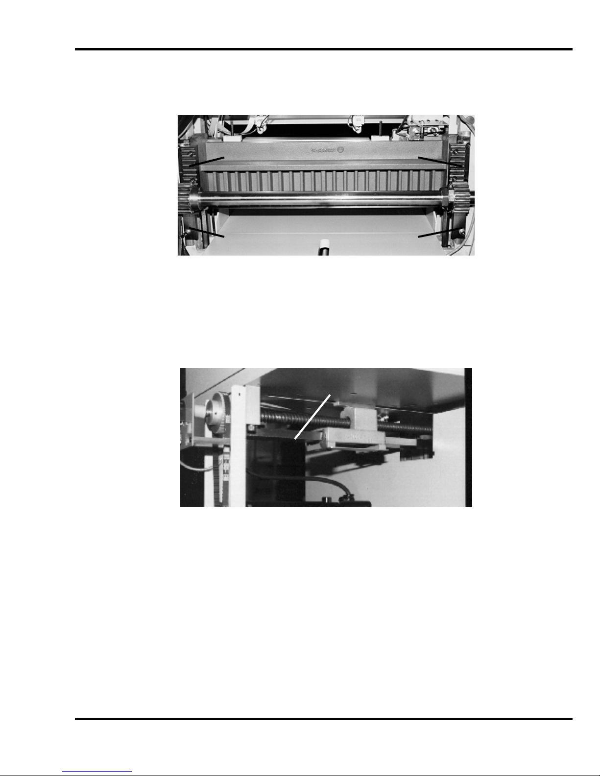
8.0 Oil and Grease
Grease Grease
Grease Grease
Figure 26 – Clamp Gibs and Rack & Pinion
Grease
Figure 27 – Backgaug e Guide
49
Page 50

9.0 Safety Systems Test
9.0 Safety Systems Test
Machine manufact ur er CHALLENGE Model TITAN 265
Serial Number __________________
Frequency of test: THESE TESTS S HOUL D BE PERFORMED AT THE BEGINNING OF EACH
WORK DAY.
Turn the power on and press CLEAR to pr eset the backgauge. Make sure the knife and cl am p are in
the up positi on (if they ar e not, follow the instructions in this manual to send them up).
Test #1: Wave a test object 12mm i n diameter between the electric eye beams. The indic ator lights
should indic ate the eyes are blocked. If they do not, do not use the machine. Repair or adj ustm ent is
needed.
Test #2: While making a cut, lean into the electric eye beams. The knif e and cl amp should
immediately r eturn to the up position. If they do not, do not use the machine. Repair or adjustment is
needed.
50
Page 51

9.0 Safety Systems Test
Please enter date and initials for both tests.
Date ______ ______ ______ ______ ______ ______ ______ ______ ______ ______ ______
Test 1 ______ ______ ______ ______ ______ ______ ______ ______ ______ ______ ______
Test 2 ______ ______ ______ ______ ______ ______ ______ ______ ______ ______ ______
Date ______ ______ ______ ______ ______ ______ ______ ______ ______ ______ ______
Test 1 ______ ______ ______ ______ ______ ______ ______ ______ ______ ______ ______
Test 2 ______ ______ ______ ______ ______ ______ ______ ______ ______ ______ ______
Date ______ ______ ______ ______ ______ ______ ______ ______ ______ ______ ______
Test 1 ______ ______ ______ ______ ______ ______ ______ ______ ______ ______ ______
Test 2 ______ ______ ______ ______ ______ ______ ______ ______ ______ ______ ______
Date ______ ______ ______ ______ ______ ______ ______ ______ ______ ______ ______
Test 1 ______ ______ ______ ______ ______ ______ ______ ______ ______ ______ ______
Test 2 ______ ______ ______ ______ ______ ______ ______ ______ ______ ______ ______
Date ______ ______ ______ ______ ______ ______ ______ ______ ______ ______ ______
Test 1 ______ ______ ______ ______ ______ ______ ______ ______ ______ ______ ______
Test 2 ______ ______ ______ ______ ______ ______ ______ ______ ______ ______ ______
Initials of
Repairs Repairer Date
_________________________________________ ________ _____________
_________________________________________ ________ _____________
_________________________________________ ________ _____________
_________________________________________ ________ _____________
_________________________________________ ________ _____________
_________________________________________ ________ _____________
_________________________________________ ________ _____________
_________________________________________ ________ _____________
_________________________________________ ________ _____________
_________________________________________ ________ _____________
_________________________________________ ________ _____________
_________________________________________ ________ _____________
_________________________________________ ________ _____________
51
Page 52

F.265XG-EO
January 2014
 Loading...