

Page 1

The Challenge Machinery Company provides owner's manuals on its
products s olely as a court esy to i ts cust omers. Se e the inf ormati on belo w
before using this manual.
These manuals are for reference only. These manuals include products which are noncurrent,
unsupported or no longer pr oduced by The Chal l enge M achi nery Com pany , and are pr ov ided sol el y as
an accommodat i on to our c ustom ers. By prov i ding these m anuals, T he Ch al lenge M achi nery Com pany
makes no representation or warranty as to the products, their current condition, or their suitability or
fitness for use in any particular application, which are the sole and i ndependent responsibility of the
product owner and user.
Older produ cts may not co mply with curren t safety pro cedures, guidel ines or regu lat ions, and i t
is the product owner's and user's responsibility to evaluate the suitability and fitness of the
products in their current use and application. The Challenge Machinery Company makes no
representation, warranty or recommendation regarding any modifications which may be
required on non -current o r u nsuppo rted prod ucts. T he Ch allenge Mach inery Co mpan y assumes
no liability for any modification or alteration to any Challenge product, and any such
modification or alteration to any Challenge product is not authorized by The Challenge
Machinery Comp any. The av ailabilit y of t hese manuals is sol el y for t he purpose of provi ding ref erence
information for the products.
This manual may not be complete in all aspects of product maintenance and repair. All products
should be used only by qualified and properly trained personnel, following proper safety
procedures. Al l product s should be regular l y i nspected and m aintai ned, and their condition, appli cation
and use should be periodically evaluated by qualified personnel. Only qualified and properly trained
technicians should perform maintenance, repair and replacement procedures. Attempting these
procedures without pr oper training may cause machine dam age or operat or injury!
Products may be unsup por ted by The Chall enge M ac hinery Company due to age or the unavailability of
parts from their ori ginal m anufactur er. No parts or produc t support will be available to repair or maintain
unsupported prod uc ts. Older products may not be UL listed (if the product does not have a UL l abel it i s
not a listed product), and may not comply with applicable installation or other regulations or
requirement s if rel ocated to a new f acilit y. Many munici palities requi re a product t o be UL l isted bef ore
an electrician will connect power to them. Oft en the cost of updati ng an older product to comply wit h
current saf ety r egulations is greater than the v alue of t he product .
The Challeng e Machin ery Comp any
6125 Norton Center Drive
Norton Shores, MI 49441-6081 USA
ChallengeMachinery.com
F.185SA-O
SPARTAN 185 SA
Operator’s Manual
Serial Numbers 051001 & Up
Sold and Serviced by
January 2014
Page 2

1.0 Introduction
1.0 Introductio n
THIS MANUAL is designed to help you get the most from your Challenge equi pment. Keep this
manual in a safe, conv enient place for quick reference by operators and service personnel.
SAFETY ALERT! This symbol means CAUTION: Person al safet y
instructions! Pay special attention to the instructions in bol d ty pe. Personal injury may result if the
precautions are not r ead and followed.
READ THIS MANUAL BEFORE OPERATING! Follow precauti ons and i nstr uc tions. If after reading
the manual questions still remain, contact y our Aut hori zed Chal lenge Dealer.
Take a few minutes right now to RECO RD YOUR MACHINE S E RIAL NUMBER in the space
provided on the front cover of this manual. Also be sure to fill out the warranty card accompanying
your machine and r eturn it DIRE CTLY TO CHALLEN G E .
If you bought a used machine, it is important to have the following information on record at Chall enge.
Copy this page, fill in the information and send it care of The Challenge Serv ice Department, 6125
Norton Center Driv e, Norton Shores MI. 49441.
CHALLENGE MODEL SERIAL NUMBER
ATTN COMPANY
ADDRESS
CITY STATE/PROVINCE ZIP
PHONE DATE INSTALLED
DEALER NAME & CITY
* WARRANTY INFORMATION *
It is very important that y ou r ead and under st and the conditions outli ned in the Warr anty Information
Sheet att ached to the outside of the shipping cont ainer of your machine.
The Warr anty Inf or m ation Sheet must be filled out completely and returned to THE CHALLENGE
MACHINERY COMPANY in order for the warranty to be issued for this machine.
Challenge® is a registered trademark of The Challenge Machinery Company• 6125 Norton Center Drive• Norton Shores MI.
49441 Copyright© 2006 by The Challenge Machinery Company. All rights reserved. Printed in the U.S.A
2
Page 3

1.0 Introduction
TABLE OF CONTENTS
1.0 Introduc tion................................................................................................................................. 2
2.0 Safety.........................................................................................................................................4
2.1 Precautions.............................................................................................................................4
2.2 Power Lockout Proc edur e .......................................................................................................4
2.3 Warning Label Definitions........................................................................................................5
3.0 Packing List.................................................................................................................................7
4.0 Specifications..............................................................................................................................8
5.0 Installation & Setup.....................................................................................................................9
5.1 Inspecting Shipment................................................................................................................9
5.2 Uncrating................................................................................................................................9
5.3 Cleaning ............................................................................................................................... 10
5.4 Power Hook-Up.....................................................................................................................10
6.0 Operation.................................................................................................................................. 11
6.1 Power – Main Switch.............................................................................................................11
6.2 Backgauge Control ................................................................................................................ 11
6.3 Jogging Aid........................................................................................................................... 12
6.4 Line Light.............................................................................................................................. 12
6.5 Making a Cut.........................................................................................................................13
6.6 Adjusting the Knife Depth......................................................................................................13
6.7 Operating Tips......................................................................................................................13
7.0 Knife Installation/Changing........................................................................................................ 14
7.1 Knife Removal....................................................................................................................... 14
7.2 Knife Installation....................................................................................................................15
7.3 Knife Care Tips..................................................................................................................... 16
7.3.1 Knife Blade Life.............................................................................................................. 16
7.3.2 Cutting Stick...................................................................................................................17
7.3.3 Bevel Angle ...................................................................................................................17
7.3.4 Helpf ul Suggestions....................................................................................................... 17
7.3.5 Knife Care......................................................................................................................17
8.0 Maintenance and T r oubleshooting.............................................................................................18
8.1 Maintenance ......................................................................................................................... 18
8.2 Troubl eshooting.................................................................................................................... 18
9.0 Safety Systems Test................................................................................................................. 20
3
Page 4
2.0 Safety
2.0 Safety
2.1 Precautions
• This machine i s designed f or one- per son operation. Never operate the machine with more than
one person.
• Safe use of this machi ne is the r esponsibility of the operator . Use good judgment and common
sense when working with and around this machine.
• Read and understand all instructions thoroughl y before using the machine. If questions remain,
contact the deal er from whic h y ou purchased this machine. Failure to under stand the operating
instructions may result in personal injury.
• Only trained and aut hor iz ed people should operate this machine.
• DO NOT ALTER SAFETY GUARDS OR DEVICES. They are for your protection. Severe
personal injury may result.
• Disconnect power before cleaning or performing maintenance. See Section 2.2 Power Lockout
Procedure.
• Observe all cauti on labels on this machine.
• Be sure the cutter i s properly grounded.
• Be sure there is sufficient power to operate the cutter properly.
• Observe all cauti on plates mounted on this cutter.
• Keep foreign objec ts off table and away from cutter blade.
• BE EXTREMELY CAREFUL when handling and changing the cutt er knif e. Severe lacerations or
dismemberm ent could result from careless handling pr oc edur es.
• Keep the floor around the cutter free of trim, debris, oil and grease.
• When replacing hy dr aulic parts, loosen the connections slowly to release pressure. Never loosen
connections with the machine running.
• If the cutter sounds or operates unusually, hav e it checked by a qualified service person.
• CRUSH HAZARD, keep hand and fingers from under the clamp when clamping paper . Use
Jogging Aid to load paper , and use the backgauge to push paper out before unloading. DO NOT
REACH UNDER THE KNIFE AND CLAMP AREA!
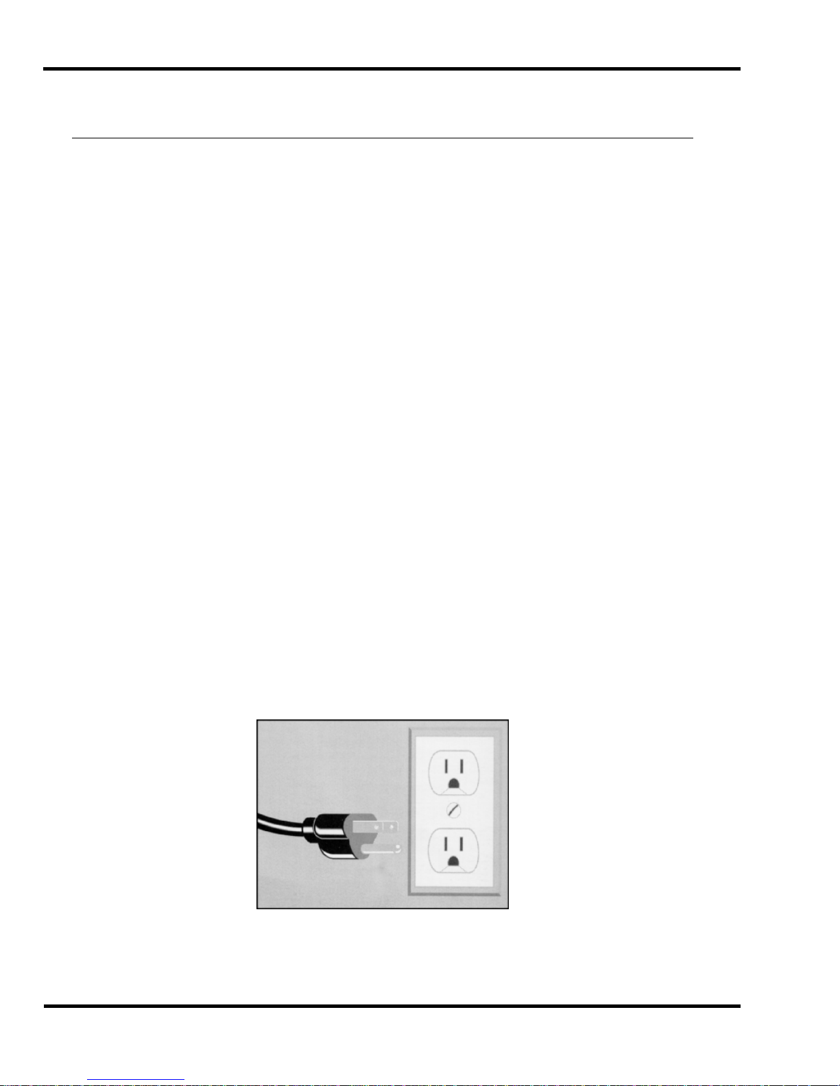
2.2 Power Lockout Procedure
For maximum safety while making adjustments or repairs to y our machine, be sure to disconnect
power to the machine. Disconnect the power plug from its socket
Figure 1 - Main Power Disconnect
4
Page 5
2.0 Safety
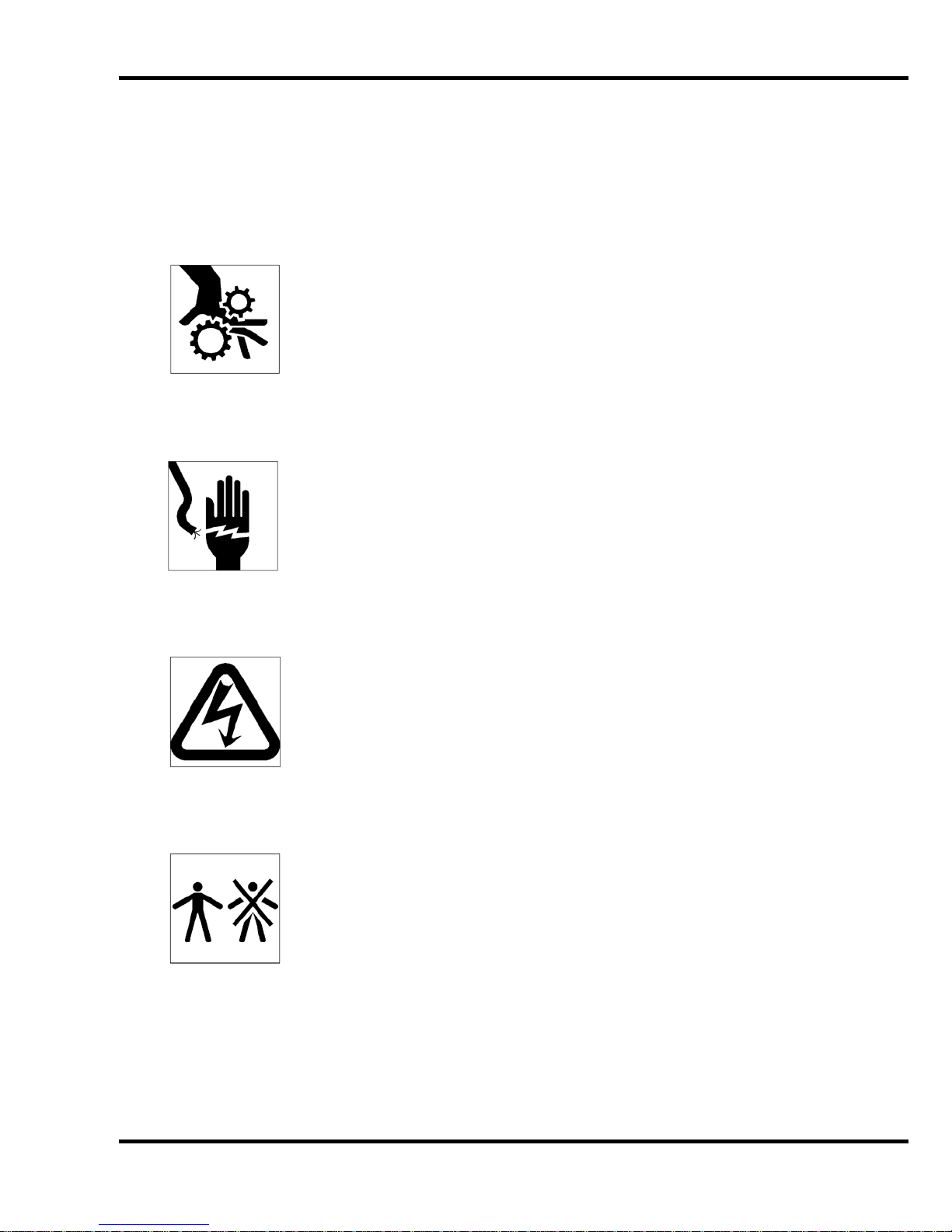
2.3 Warning Label Definitions
The following warni ng labels are found at various loc ations on your machine. Read and understand
the meaning of each symbol. If a label is lost from the machine, it should be replaced.
HAZARDOUS AREA
Disconnect power bef or e cl eaning, servicing, or m aki ng adjustm ents not requiring
power. Do not alter saf ety guar ds or devices; they are for your prot ection. Replace
all guards. Do not operate with any guards removed.
SHOCK HAZARD
Disconnect power bef or e r em ov ing cover. Replace cover before operation.
SHOCK HAZARD
Disconnect power bef or e r em ov ing cover. Replace cover before operation.
SINGLE OPERATOR
Do not operate with m or e than one person.
5
Page 6

2.0 Safety
!OJO!
This Este simbolo de alerta de seguridad significa ¡ OJO ! INSTRUCCIONES DE SEGURIDADPERSONAL. Lea las i nstrucciones po rque se refieren a su
seguridad personal. Fall de obedecer las instrucciones que siguen podria resultar en lesiones
corporales.
• Esta maquina, junto con sus mecanismos de seguridad, esta disenada para ser manejada por
• UNA SOLA PERSONA a la vez. Jamas debe ser manejada por mas de una persona al mismo
• tiempo.
• La seguridad es la responsabilidad del operario que usa esta maquina.
• LEA DETENIDAMENTE el manual de instrucciones y las PRECAUCIONES DE SEGURIDAD
antes de poner a funcionar la c or tadora. Pidale a su supervisor una copia.
• El manejo de la guill otina debe estar exclusivamente a cargo de per sonal entrenado y autoriz ado
para ello.
• NO MODIFIQUE LOS MECANISMOS DE SEGURI DAD, estan ahi para su proteccion no deben
ni modificar se ni quitarse.
• DESCONECTE LA CORRIENTE ELECTRICA antes de proceder a hacerle servic io de limpieza,
engrasar, o de hacer adjustes que no requieren corrient e. Trabe el interruptor en la posicion
OFF (apagado); vea “Procedimiento para cortar la corriente elect ri c a” al pi e de esta pagi na.
• Eche llave a la guillotina y quite la llave cuando la maquina no esta en operacion; vea “Corriente
electrica”.
• Asegurese de que la guillotina este debidament e a tierra. V ea “Conexion de la fuerza electrica”.
• Verifique el v oltaje y asegurese de que este sea suficient e par a el debido funcionamiento de la
guillotina.
• Preste atenci on a todas las pl ac as con advertencias instaladas en esta guillotina.
• No permita que objetos estranos esten en la mesa o cerca de la cuchilla cort ador a.
• TENGA SUMO CUIDADO al tocar y cambiar la cuchilla. Heridas severas y hasta
desmembrami ento pueden resultar del manejo sin cui dado o negligente.
• El suelo alrededor de la guillotina debe mantenerse despejado y libre de recortes, desperdi c ios,
aceite y grasa.
• Al haber la necesidad de r eem plazar partes hidraulic as, afloje todas las conexiones poco a poco
para dejar escapar l a pr esi on. Jamas debe aflojarse conexiones mientras la maquina este
• andando.
• Si la guillotina empezara a sonar o trabajar difer entemente a lo acostumbrado, desconectela y
consulte la seccion “Troubleshooting” ( Reparador) de este manual. Si no es posible corregir el
problema, llam e a su servi ci o autorizado para que le examinen la maquina.
• PELIGRO DE MACHUQUE - Mantenga manos y dedos f uer a de la agar r ader a mi entras sujeta el
papel. Use el calibr ador trasero y su rueda de mano para empujar el papel cortado. NO PONGA
SUS MANOS BAJOLA CUCHILLA O AREA DE LA AGARRADERA.
• NO OPERE SIN LAS GUARDAS PROTECTORAS!
¡ OJO ! PRECAUCION - Como proceder para desco nect ar
la corriente electrica.
Para maxima seguridad durante ajustes y reparaciones de su maquina, verifique bien que el interruptor principal
de control de corriente al cual la maquina esta conectada, este desconectado. El interruptor deba ser puesto en
la posicion “OFF” (desconectado) y se debe poner un candado en la anilla. La llave del candado debe ser
guardada por la persona que estara efectuando los trabajos de servicio o de reparacion en la guillotina.
Desconecte la corriente electrica antes de proceder a hacer cualquier ajuste o reparacion o de efectuar el
engrase en cualquier maquina.
6
Page 7

3.0 Packing List
3.0 Packing List
Part No. Description Qty.
Spartan 185 SA 18-1/2” Semi-Automatic Paper Cutter 1
F.185SA-O Operator Manual 1
63073 Knife Lifter Assembly 1
63017 Knife – Standard (installed in machine) 1
63015 Cutting Stick (installed in machine) 1
A-12608-2 Jogging Aid 1
W-191 3/16” Hex ‘T’ Allen Wrench 1
5064 Cutting Stick Puller 1
Knife Scabbard
Machine Lifter Handles 4
Optional Items
Part No. Description Qty.
63015 Extra Cutting Sticks 1
63017 Knife – Standard 1
63017-1 Knife – Long Lasting H.S.S. 1
7
Page 8

4.0 Specification s
4.0 Specificati ons
Description Inch Units Metric Units
Cutting Width 18-1/2” 47 cm
Minimum Cut 1” 2.5 cm
Clamp Opening 3” 7.6 cm
Table Space
Front:
Back:
Dimensions
Overall Height 52-3/4” 134 cm
Table Height 36” 91.4 cm
Overall Length 41” 104 cm
Overall Width 32-1/4” 82 cm
Approx. Net Weight 570 lbs 260 kg
Approx. Shipping Weight 700 lbs 318 kg
Electrical
120 Volts 60 HZ. 16 Amps, Service Size 20 Amps Receptacle NEMA 5-20R
Challenge reserves the right to make changes to any product or specif ication without notic e and
without inc ur ri ng r esponsibility to existing units.
13”
17-1/2”
33 cm
44.5 cm
8
Page 9

5.0 Installation & Setup
5.0 Installation & Setup
5.1 Inspecting Shipm ent
This machine has been carefully packed to prevent damage during shipment. However, claim s f or
damage or loss are the responsibility of the recipient. Inspect all shipment s as soon as they are
received. If there is any noticeable damage, note it on the fr eight bill. Visual and/or hidden damage
must be report ed to the claims department of the carrier within 15 days. Contact your dealer if you
need any assistance. Check the contents of the box against the packing list on page 7. Make sure
there are no missing items.
5.2 Uncrating
The Spartan 185 SA weighs approx imately 600 lbs (272 kg). DO NOT risk personal injur y or damage
by attempti ng to mov e machinery with makeshift equipment or inadequate help. This machine is
shipped on a wooden skid and enclosed in a protective, wooden frame and corrugated carton.
Remove the cart on by remov ing the nails or staples holding it to t he wooden frame and lift it straight
up over the cutter.
Figure 2
Remove all tape and plastic wrapping. Remove the (4) lag screws from the base of the machine and
(4) lag screws from the support blocks. Insert lifting handles. While lifting one side of t he m achi ne at
a time, remov e the support blocks and set aside. Unscrew ramp from skid, and position as shown in
Figure 3. Secure ramp to ski d usi ng (2) nails where indicated by red circl es on ramp.
Figure 3
9
Page 10

5.0 Installati on & Setup
Clear area in fr ont of ramp. Using two or more persons, carefully r oll m ac hine off skid using lifting
handles as shown in Fi gur e 4.
Figure 4
Remove lifting handles and roll machine into positi on. Lock casters to prevent machine from
inadvertently rolling.
5.3 Cleaning
After unpacki ng, wipe down all machine panels and surfaces with a clean cloth.
5.4 Power Hook -U p
SHOCK HAZARD! NEVER CUT THE GROUND TERMINAL from a three-
prong plug to fit a two-prong socket. Possible shock could c ause personal injury or death. Hire a
qualified elec trician to provide a power source that meets electrical requirem ents and all local
electric al c odes.
It is the customer’s responsi bility to provide a pr operly grounded receptacle t hat meets the power
requirement s specified on the nameplate of thi s machine, as well as all loc al electrical codes. Have a
qualified elec trician install one if your location is not so equipped. The socket- outlet shall be installed
near the machi ne’s l oc ation and be easily accessible.
Connect the power cord i nto a grounded, 3-prong receptacle only!
Service Size 20 Amps Receptacle NEMA 5-20R
120 Volts 60 HZ. 16 Amps,
10
Figure 5
Page 11

6.0 Operation
6.0 Operation
IMPORTANT: DO NOT ATTEMPT TO OPERATE THE CUTTER UNTIL
YOU HAVE THOROUGHLY READ AND UNDERSTAND ALL OF THE FOLLOWING
INSTRUCTIONS. CALL YOUR AUTHORIZE D CHALLENG E DEALER IF YOU STILL HAVE ANY
QUESTIONS.
6.1 Power – Main Switch
Power is enabled when the main power switch is turned to the “ON” posit ion (Figure 6). The display
and line light ar e tur ned on at t his tim e.
Figure 6 –Power On-Off Switch and Circuit Breaker
If the knife is not at the “up” postion when the main power switch is turned
on, the knife will automatically move to the “up” position.
NOTE: The main power switch is also a cir c uit breaker and will automatic ally swit c h off in the event
of too much current running through the switch, such as fr om an el ectri c al short. To reset the circuit
breaker, simply push the switc h to the “on” position.
6.2 Backgauge C ont rol
The backgauge is used to posit ion paper to the desired location when cut ting. The backgauge is
operated by the hand cr ank at t he front of the machine. The backgauge position is shown by a
lighted LED display . When the machine is first powered up, the display shows f our lines as follows,
indicating the display needs to be reset.
Figure 7 – Display at power up
11
Page 12

6.0 Operation
To reset the display, bring the backgauge to the forward most posit ion. If the backgauge is already at
the forward most posi tion, move the backgauge back by a few turns, then bring it forward again. Now
the display shoul d show the actual position of the backgauge (Figure 8). The position of the decimal
point indic ates whether the r eading is in inches or millimeters. Two digits to the right of decimal
indicates inc hes, one digit to the right of decimal indic ates m illimeters. To switch from inches to mm
and vice versa, pr ess the i nc h/mm button located next to the display.
Figure 8 – Display with backgauge at 1.00 inches
6.3 Jogging Aid
Always remove the joggi ng aid from the table before making a cut.
A jogging aid is included as standard equipment with t he Spartan 185 SA. This tool allows the
operator to load and align paper without the need to place hands or arms under the knife or clamp.
To use, load the paper agai nst the side and backgauge using the joggi ng aid. Remove the jogging aid
from the tabl e, close the shi eld, clamp the paper, and make the cut.
Figure 9 – Jogging Aid
6.4 Line Light
The Spartan 185 SA comes standard wit h an LE D line light. The line light comes on and stays on
whenever the power i s on. To use, sim ply align paper under clamp, and use the red light line as an
indicator of where the cut will be made.
12
Page 13

6.0 Operation
6.5 Making a Cut
Open the front shield and set the backgauge to the desired positi on. Place the paper square against
the backgauge and either side guide. Clamp down on the paper using the cl amp hand wheel located
on top of the machine. Now close the fr ont shield then press and hold both cut butt ons (located on
the front face of t he machine). Hold the buttons in until the knife r eac hes the table. Now release the
cut buttons and the k nife will return to the “up” position and the fr ont shield will automatically open.
Note: releasing t he c ut but tons or raising the shield at any time duri ng the cut cycle will immediately
send the knife t o the “up” posit ion. Raise the clamp by turning t he hand wheel and remove the cut
pieces of paper.
Note: The front shield must be opened and closed each time a new cut is to be made.
See Section 6.7 Operating Tips, page 13 for more inform ation about clamping and cutting.
6.6 Adjusting the Knife Depth
The depth of cut can be adjusted usi ng the knife depth adjusting screw locat ed on the right side of the
machine. The same T-handl ed wrench used for changing the knife c an be used to adjust the screw.
Turn the screw clock wise to increase knife depth, and counterclockwise to decrease knife depth. It is
better to make sev er al sli ght adjustments and perform test cut s i n between, than to make large
adjustments and cut too deep. Try to avoid setting the knife too deep as this can cause premature
wear on knife and/or dam age the cut stick.
Figure 10 – Knife Depth Adjustment
6.7 Operating Tip s
• For best results, it is a MUST to have a sharp blade in the cutter. A dull blade will pull or
draw the paper and cause uneven cutting.
• Carefully lay out each sheet before cutting. Find the best cut pat tern that gives the most
pieces out of the sheet. If the sheet will be folded, be sure the grain of the paper i s running in
the same directi on as the fold to avoid getting a rough edge on the fold.
• Mark the gripper edge and the guide edge of printed paper and make sure the fi r st c uts are
with these guide edges against t he bac k gauge.
• When cutting busi ness card s or narr ow str ips of paper, place lift s of equal height on opposite
sides of the tabl e to prov ide better clamping.
13
Page 14

7.0 Knife Installat io n/ Changing
7.0 Knife Installation/Changing
Changing knives can be very danger ous unl es s saf ety precautions are
observed and extrem e c ar e is tak en when handling knives.
• Make sure knife lift er s are used properly, see instructi ons following.
• Keep handling of unprotected knives to an absolute minimum.
• Clear off cutter table before removing knife.
• Have scabbard nearby and insert knife immediately .
• Warn people of any unprotected knife.
• Knife changing is a ONE PERSON OPERATION. Having m or e than one person tr y ing to
change kniv es invites accidents.
3/16”
T-Wrench
Knife Lifter
Assembly
Knife
Scabbard
Figure 11 – Spartan 185 Knife Change Accessories
The knife changing equipment shown in Figure 11 is included with the machine. The following
instructions show how to remove and install a new or re-sharpened knife. Read through these
instructions AT LEAST ONCE before attempting to actually change or install any blades.
7.1 Knife Removal
1. With no paper in the machine, make a cut and when the knife reaches the table, continue to hold
the left cut button while turning off power with your right hand. This will keep the knife in the
down position. Di sconnect the machine power cord and remove the right-most knife screw
ONLY. Restore power to the machine, turn the switch on, and the knife shoul d m ov e to the “up”
position. Turn the main power swit ch off and disconnect the machine power cord.
2. Raise the knife depth of cut all t he way up by turning the knife adjusting screw locat ed on the right
side of the machine c ounterclockwise until it start s to unscre w out of the machine (see Section
6.6 , p. 13). This will ensure the new knife will not cut too deep since a new knife will c ut deeper
than one that has been ground several times.
NOTE: Failur e to rai se the k nife depth could damage the new knife and/or the c utti ng st ic k .
3. Rem ov e the t wo knife bolts from the slotted
assembly (Figure 12). Tighten the lif ters to hold the knife in place, and t hen r em ov e the
remaining thr ee k nife bolts.
knife bar holes ONLY and replace with the knife lifter
14
Page 15

7.0 Knife Installation/Changing
Figure 12
4. Clear the table surface and place the empty knif e scabbard on a flat surface nearby. Remove the
scabbard’s knife retaining screws.
5. Grasp t he k nife lifters firmly and, at t he same time, turn them counterclockwise to release the
knife from the knife bar. Lower the entire assembly down, then move the knife to the left slightly
then bring the knif e out of the cutt er , right end first. Put the blade in the scabbard immediately,
remove the knife lift er assembly, and secure the knife with t he k nife retainer screws.
6. Send dul l k nives to a knife grinder – do not attempt to sharpen your own knives! Knives that do
not have a minimum height of 2-3/8” (6.0 cm) will not function properly and should be carefully
discarded. See t he Knife Care Tips Section 7.3 page 16 for additional information.
7.2 Knife Installation
Knives are heavy and always very sharp! Be sure to keep the edge away
from your body and keep other people out of the area while handling the blade. Severe lacerations or
dismemberm ent could result from careless handling pr oc edur es.
1. Make sure t he k nife bar is in the “up” position. Turn the mai n power switch off and
disconnect the m ac hine power cord to prevent accidental power-up while servicing the cutt er .
2. Pull out the cut stick and turn it to a new surface or replace with a new one.
3. Rem ov e the r etainer screws from the new blade and screw the knife lifters into the new
blade. Screw the lift er s about half way into the knife.
4. Insert the knife assembly into position under the knife bar, left end fi r st . Raise the knife into
the knife bar slot as high as i t will go. Check both view holes to make sure knif e is all the way
up (Figure 13). Then tighten the lifters.
NOTE: If the blade will not go in, make sure the lifters are not screwed into the bl ade too f ar.
View Hole View Hole
Figure 13
15
Page 16

7.0 Knife Installat io n/ Changing
5. Insert and tighten the three accessibl e k nife bolts.
6. Rem ov e the knife lifter assembly and replac e with the two knife bolts.
7. Pl ug in power cor d, turn power on, close the shiel d and press the cut but tons to send knife
and clamp down. Continue t o hold the left cut button while turning off power with your r ight
hand. This will keep t he knife in the down position. Disconnect the mac hine power cord and
insert and tight en the right-most knife screw.
8. Restore power to machine, and place a few sheets of paper over the cut stick, cov eri ng the
stick end-t o- end.
9. Double c hec k to make sure the knife depth adjusting screw has been adjusted up (step #2,
Knife Removal). Pl ug in the power cord, turn the power on, close the shiel d, and press the
cut buttons to perform a cut cycle.
10. If the knife does not cut all the way through (and it shouldn’t on the first try), adj ust the knife
depth of cut by turni ng the adjusting screw on the right side of the m ac hine, about one
complete turn at a time to start. Continue to make cuts and adjustment s until the knife cuts
through all sheets. Remove paper and cut through a few larger lifts of paper to make sure
the knife depth is set corr ec tly. Adjust again if necessary.
11. Send dull knives to a knife grinder – do not att em pt t o sharpen your own knives! Knives that
do not have a minimum height of 2-3/8” (6.0 cm) will not functi on pr operl y and should be
carefully di scarded. See the Knife Care Tips Section 7.3 page 16 for addit ional information.
7.3 Knife Care Tips
! KNIFE SAFETY ! Knives are DANGEROUS!!! Knives are very sharp,
even after use. Keep the edge away from your body and keep the area clear of others when handl ing
knives. Never touch the cutting edge! To prevent personal i njur y and damage to the knife, always
keep knives in their holders with screws tightened. Even if you ar e aware of the dangers, others may
not be. Never attem pt to hone, polish, or service the knife in any way. Failure t o follow safety
procedures may resul t in severe lacerations or dism emberment.
7.3.1 Knife Blade Life
Knife blade lif e, or the time between sharpening, can be affected by many factors. One important
factor is the type of paper being cut. Abrasive paper, such as recycled paper, soft paper such as
newsprint paper, and bound book s can all significantl y shorten knife blade life. Also, if t he k nife depth
is set too deep, the knife will cut too deep into the cutting stick and c an quickly dull the knife blade.
A knife can last between 2,000 and 5, 000 c uts before it needs to be sharpened. Cutti ng soft paper
(such as newsprint paper) or paper with high post-consumer recy cl ed c ontent can cause the knife to
need sharpening after only 2,000 to 3,000 cuts. Cutti ng pure paper, such as bond paper with no
recycled content, or hard paper can allow the knife to be used for as many as 5,000 cuts before it
needs to be sharpened. In all cases, the oper ator should continually check the quality of the cut to
determine when the knife blade needs to be sharpened. Som e characteristics that indic ate a blade
needs sharpening are:
• The knife hesit ates or stalls while making a cut.
• The sheets are not all cut t o the sam e length (usually the top few sheets are longer t han the
rest of the sheets - this is sometimes called “draw”).
16
Page 17

7.0 Knife Installation/Changing
• Cut marks appear on the cut f ac e of the paper.
• The profil e of the cut (side v iew) is not perpendicular to the t able.
• The cut does not appear straight when viewed from the top.
• The knife makes a “rough” sound as it passes thr ough paper .
• Nicks are vi sibl e on the cutti ng edge of the knife.
7.3.2 Cutting Stick
A worn cutting stic k can affect the cut quality of the bottom sheets. W hen this happens, the cut stick
can be rotated. Usuall y, the stick should be rotated one or two times between knife sharpening. Cut
sticks have a “wavy” shape to them and when rotated must be rotated a f ull 180° t o k eep a flat side
up. Each stick has 2 flat sides that c an be used, aft er which i t can be turned end to end, allowing the
2 flat sides to be used again, for a total of 4 positions per cut stick.
7.3.3 Bevel Angle
Challenge recommends that bevel angles for the Spartan 185 knives be 21°.
7.3.4 Helpful Suggestions
• It may be helpful to own a “set” of knives. A set consists of 3 knives: one in the machine,
one as back up, and one at the grinder .
• If the machine seems to str ain but the cut quality is still good, reduce the pile height. You
may also carefully apply glycerin to the bevel when cutting hard, coated paper. Tie a cloth to
the end of a stick; di p the stick in gly cerin, and apply. Never apply by hand! In lieu of
glycerin you m ay li ghtly rub white bar soap along the bevel. Lubri c ation will prolong the life of
your machine and r educ e m aintenance.
7.3.5 Knife Care
• To prevent corrosion, knives are coated with light oil. It should be REMOVED WITH CARE.
• While removi ng or i nstalling a knife, be careful not to allow the edge to bump against the
machine. Nicks will result.
• If a knife bolt is damaged, r eplace it.
• Always keep knife bolts securely tightened.
• Store knives in a dry envir onm ent to prevent corrosion.
• Never attempt t o hone, polish, or service the knife in any way.
17
Page 18

8.0 Maintenance and Troubleshooting
8.0 Maintenance and Tro u bleshooting
8.1 Maintenan ce
All maintenance on this machine should be performed by trai ned service
personnel. Attempting to perform repair and replac ement pr oc edur es without proper training m ay
cause machine dam age or oper ator injury!
8.2 Troublesh ooti ng
Problem Possible Cause Solution
1. The mac hi ne will not
power up – no display,
no line light, and
machine will not cycle.
2. Displ ay and line light are
on, but machine will not
cycle.
3. Backgauge display
shows: “----“.
4. Knife cuts deeper on one
side than the other .
5. The machine strains
through a cut.
a) Power cord is disconnected.
b) Main power switch/circuit
breaker is off.
c) No power at elec trical outlet.
a) F r ont guard is open.
b) F r ont guard has not been
opened and closed since
previous cut cy cl e.
a) Bac k gauge has not been
preset.
a) Knife is not seated all the way
up in knife bar.
a) Dull knife.
b) I nadequate power source.
a) Plug in cord.
b) T ur n power switch/circuit
breaker on.
c) Check outlet. Repair or use
another outlet.
a) Close front guard.
b) O pen and c lose front guard.
a) Pr eset B ac k gauge by br inging
backgauge to front of machine
a) Loosen k nife screws and use
knife lifter assembly to raise
knife up tight. See Secti on 7.2
Knife Installation, page 15.
a) Change t he k nife with a new or
sharpened one. See Section
7.0 Knife Installation/Changing,
page 14 for instruc tions.
b) T he electrical outlet m ay not
have sufficient power if other
equipment is operating on the
same line. Try another outlet
on a different line.
6. Concave cutting – ends
wide, center narr ow.
7. Concave cutting –
variation from top to
bottom.
a) Ex c essive moisture at edges
a) Knife dull or incorrectly
18
of paper.
ground.
a) Keep paper in dry location.
a) Change t he k nife with a new or
sharpened one. See Section
7.0 Knife Installation/Changing,
page 14 for instruc tions.
Page 19

8.0 Maintenance and Troubleshooting
NOTES
19
Page 20

9.0 Safety Systems Test
9.0 Safety Systems Test
Machine manufact ur er CHALLENGE Model SPARTAN 185 SA
Serial Number __________________
Frequency of test: THESE TESTS S HOUL D BE PERFORMED AT THE BEGINNING OF EACH
WORK DAY.
Turn the power on and make sure the knife and clamp are in the up position (if they ar e not, follow the
instructions in this manual to send them up).
Test #1: With the front shield open, press the cut buttons. Nothi ng shoul d happen. If the knife
comes down with the front guard open, do not use the machine. Repair or adj ustm ent is needed.
Test #2: Close the front guard and pr ess the cut buttons. While the knife is coming down, open the
front shield. The knife should immediately return to the up position. If it does not, do not use the
machine. Repair or adjustment is needed.
20
Page 21

9.0 Safety Systems Test
Please enter date and initials for both tests.
Date ______ ______ ______ ______ ______ ______ ______ ______ ______ ______ ______
Test 1 ______ ______ ______ ______ ______ ______ ______ ______ ______ ______ ______
Test 2 ______ ______ ______ ______ ______ ______ ______ ______ ______ ______ ______
Date ______ ______ ______ ______ ______ ______ ______ ______ ______ ______ ______
Test 1 ______ ______ ______ ______ ______ ______ ______ ______ ______ ______ ______
Test 2 ______ ______ ______ ______ ______ ______ ______ ______ ______ ______ ______
Date ______ ______ ______ ______ ______ ______ ______ ______ ______ ______ ______
Test 1 ______ ______ ______ ______ ______ ______ ______ ______ ______ ______ ______
Test 2 ______ ______ ______ ______ ______ ______ ______ ______ ______ ______ ______
Date ______ ______ ______ ______ ______ ______ ______ ______ ______ ______ ______
Test 1 ______ ______ ______ ______ ______ ______ ______ ______ ______ ______ ______
Test 2 ______ ______ ______ ______ ______ ______ ______ ______ ______ ______ ______
Date ______ ______ ______ ______ ______ ______ ______ ______ ______ ______ ______
Test 1 ______ ______ ______ ______ ______ ______ ______ ______ ______ ______ ______
Test 2 ______ ______ ______ ______ ______ ______ ______ ______ ______ ______ ______
Initials of
Repairs Repairer Date
_________________________________________ ________ _____________
_________________________________________ ________ _____________
_________________________________________ ________ _____________
_________________________________________ ________ _____________
_________________________________________ ________ _____________
_________________________________________ ________ _____________
_________________________________________ ________ _____________
_________________________________________ ________ _____________
_________________________________________ ________ _____________
_________________________________________ ________ _____________
_________________________________________ ________ _____________
_________________________________________ ________ _____________
_________________________________________ ________ _____________
21
Page 22

F.185SA-O
January 2014
 Loading...