

Page 1
Portable Air Conditioner
INSTRUCTION MANUAL
Page 2

SAFETYinSTRucTionS
Thank you for choosing this innovative Challenge air conditioner. We suggest that
you keep this manual in a safe place for future reference. It describes the many
benefits and advanced features this unique product has to offer. Before you use
your air conditioner you should carefully read these instructions to maximise this
product s performance.
Challenge has specialised in complete indoor environmental control, manufacturing
portable air conditioners, coolers, air purifiers,
ionisers and aroma therapy scent diffusers. These world class products incorporate
the latest technological developments.
THAnKYou
iMPoRTAnT!
• The unit is designed for indoor operation.
• Rating: This unit must be connected to a 220-240 Hz earthed outlet.
• The installation must be in accordance with regulations of the country where the
unit is used.
necessary modified by a qualified electrician.
•This appliance is not intended for use by persons (including children) with
reduced physical, sensory or mental capabilities, or lack of experience and
knowledge, unless they have been given supervision or instruction concerning
the use of the appliance by a person responsible for their safety.
•Children should be supervised to ensure that they do not play with the appliance.
• The air conditioner is safe. However, as with other electrical appliances, use it
with care.
• Keep out of the reach of children.
• Do not clean the unit by spraying it or immersing it in water.
• Do not insert any object into the openings of the unit.
• Disconnect it from the mains before cleaning the unit or any of its components.
• Never connect the unit to an electrical outlet using an extension cord. If an outlet
is not available, one should be installed by a licensed electrician.
WARninG!
• Never operate this appliance if it has a damaged cord or plug. Do not lead the
cord over sharp edges.
• A damaged supply cord should be replaced by the manufacturer, its service agent
or a qualified person in order to avoid a hazard.
2
;and marketing dehumidifiers,
,
,
.
ked
and if
k
q
V /50
~
v
I
f you are in any doub t abou t the electrica l installation hav e it chec
Page 3
3
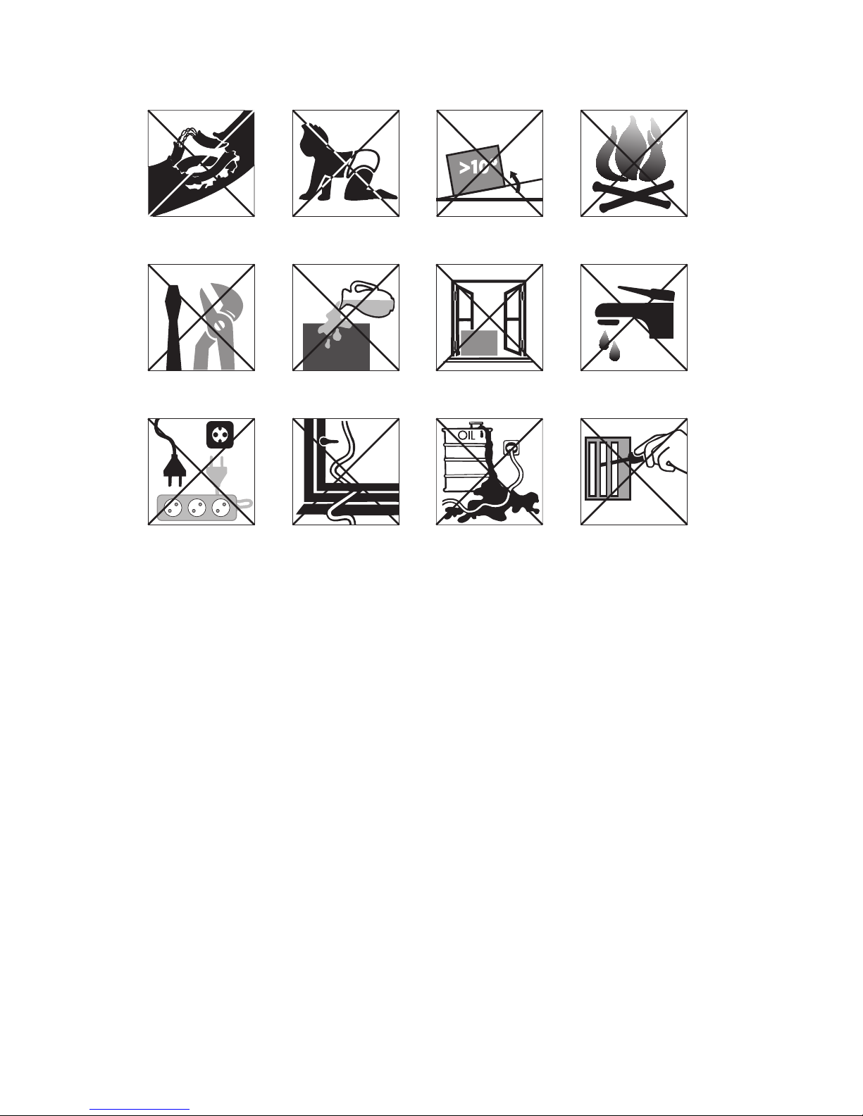
Close to a heat
source
Inside unit exposed
to the weather
outdoors
In a permanent
very humid
environment
If the power cable
wires are frayed
or cut
When small
children may be
left unattended
If an extension
lead may become
overloaded
Where the power
cable may be
damaged
On a slope or
uneven surface
Where it may
be damaged by
chemicals
Where there is a
risk of interference
by foreign objects
This products is
not made for DIY
repair
If there is a risk of
liquid falling on
the unit
Do not use your air conditioner:
Page 4
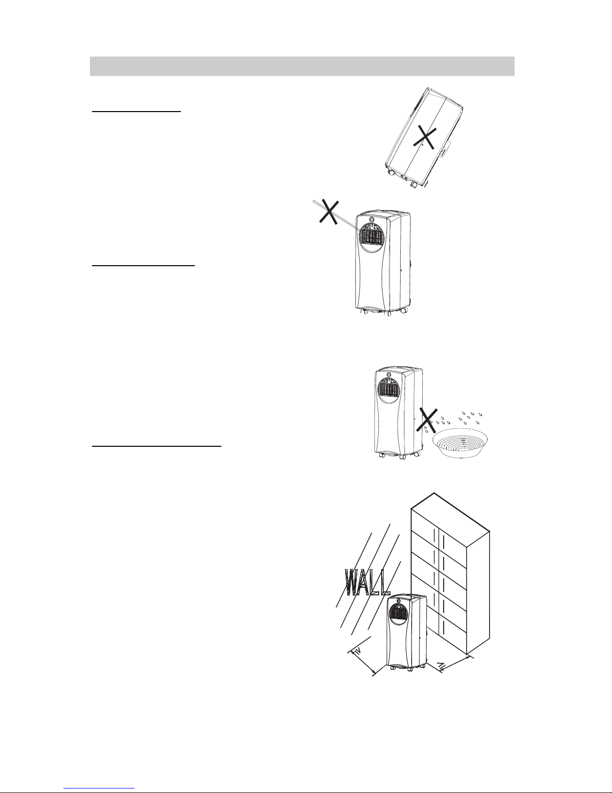
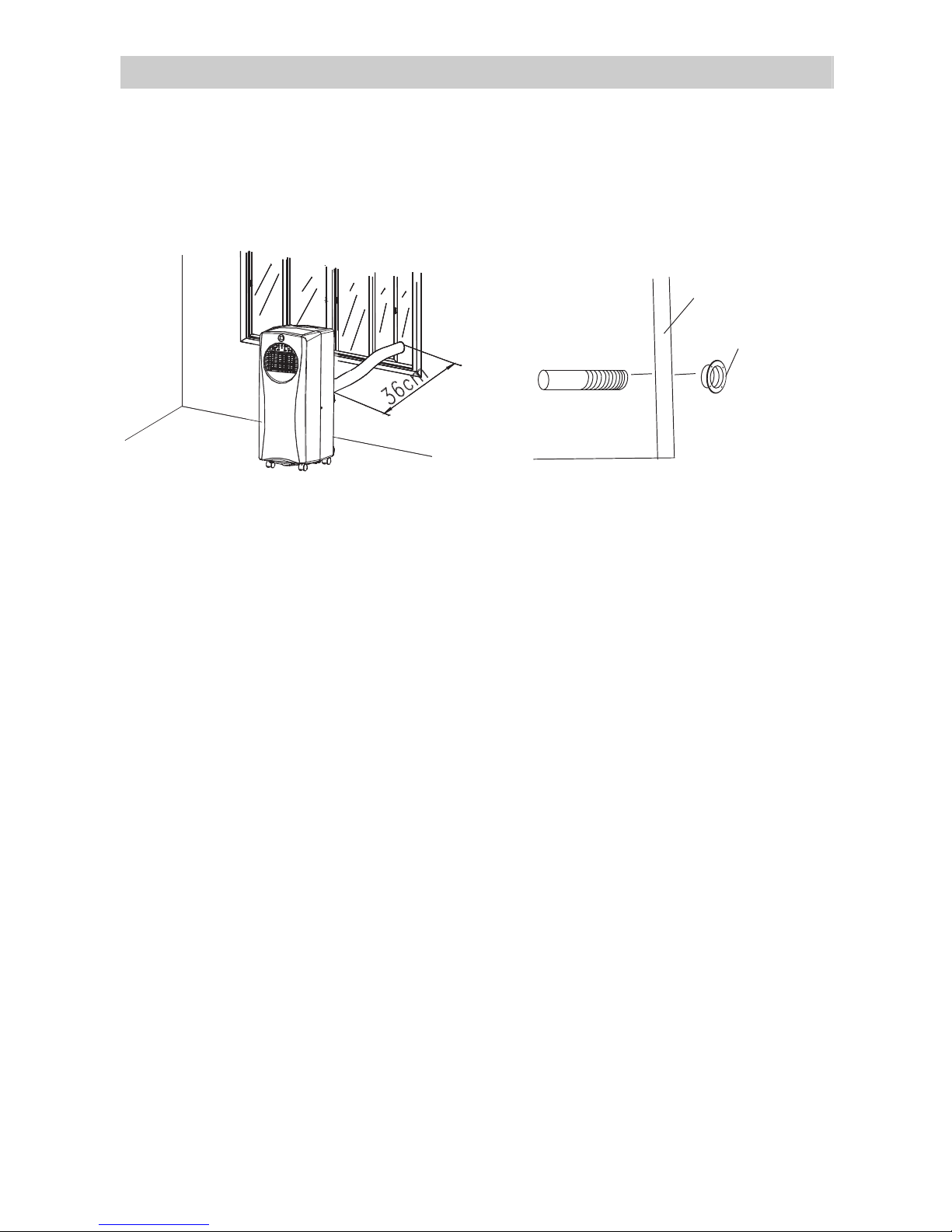
BEFORE USE
GENERAL SAFETY
• Only use in the upright position on a flat
level surface and at least 36 cm from any
objects (fig 1 & 4).
• Do not place objects on the unit or block
the air inlet / outlet (fig. 2).
• Closely supervise any children and pets
when unit is in use.
ELECTRICAL SAFETY
• For indoor use only.
• Switch off and unplug when not in use.
• Do not use in humid or wet environments
(fig 3)
• Do not pull the UNIT by the cord.
• IF THE SUPPLY CORD IS DAMAGED, IT
MUST BE REPLACED BY AN
ELECTRICIAN OR SIMILARLY
QUALIFIED PERSON, TO AVOID
HAZARD.
FOR MAXIMUM EFFICENCY
• Do not exceed the recommended room
size 50m
3
(typically 20m2 floor area)
• Close doors and windows
• Keep curtains or blinds closed during the
sunniest part of the day
• Keep filters clean
• Once room has reached the desired
conditions, reduce temperature and
ventilation settings
FIG. 1
FIG.2
FIG.3
FIG.4
36cm
36cm
4
Page 5
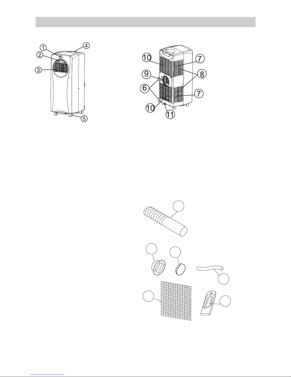
PARTS
Front Back
FIG.6
FIG.5
1.
Display
2. Control panel
3. Air outlet
4. Carrying handle
5. Caster
Accessories
12. Exhaust hose
13. Outward adapter - for insertion
over ho
se and into foam strip (or
6. Cord storage
7. Air filter
8. Air inlet
9. Exhaust air outlet
10. Air inlet
11. Wate
r stopper/drainage
12
into hole in the wall/window).
14. Round cap for filling the hole in
wall/wi
Active carbon filter
.
15
.
Drain tube for continuous
16
drain
.
Remote control
17
ndow.
age
1
5
13
5
14
16
17
FIG.7
Page 6
INSTALLATION
Installation of the exhaust pipe
The unit is a portable air conditioner that may be moved from room to room.
Using the adaptor
Wall or Window
Outward adaptor
FIG.9
• Cut a 137mm diameter hole in the wall or window.
• Feed exhaust hose through the window or wall and attach the threaded adaptor
from the outside as
• When not in use, plug the hole with the cover provided.
shown.
FIG.10
6
Page 7

Mounting of the exhaust pipe
• Use only the hose provided and
clip exhaust
hose to the back of
the air conditioner
• Avoid kinks and bends in the
exhaust hose as this will cause
expelled mo
ist air to build up
causing the unit to overheat and
shut down. Fig 11 & 12 show
correct position
• The hose may be extended from
300mm to 1
500mm but for
maximum efficiency use the
shortest length possible.
FIG.11
FIG.12
FIG.13
WARNING!
The length of the exhaust pipe is
specially designed acco
rding to the
specification of this product. Do not
replace or prolong it with your own
private hose as this could cause the
unit to mal-function.
FIG.14
7
Page 8

Installation of the carbon filter
1. Remove the filter frame from the
unit.
2. Remove the active carbon filter
from its plastic bag.
3. Insert the active carbon filter into
the back of t
4. Re-fit the filter frame inside the
unit.
he unit.
1
6
FIG.15
8
Page 9

OPERATION
Control panel
COMP
AUTO COOL
FAN FULL WATER HI
MODE
TIMER
LOW
SPEEDSLEEP
11.
Mode button
1.
2. Timer button
“ ull Water ” indicator
3.
f
4. Sleep button
5.
Fan speed
button
6. Low ventilation indicator
7. High ventilation indicator
8. Receiver for remote control
9. Sleep operation indicator
Decrease temperature button
10.
BUTTONS
Mode button
- It is for selecting Fan mode, Air-conditioning mode or auto mode.
Timer button
- It is to switch on / off the timer mode and adjust the set time for the timer.
Sleep button
- It is to switch the operation mode to sleeping mode.
Fan Speed button
- It is for selecting between the low and highfan mode.
Increase & Decrease Temperatu re button
- It is for adjusting the set temperature under the air-conditioning mode.
ON/OFF button
- It is to switch on / off the unit.
ON/OFF button
12.
Increase temperature button
13. Timer operation indicator
14. Compressor operation indicator
5.
1
Fan mode indicator
Air-conditioning mode
16.
Auto mode in
17.
dicator
FIG.16
9
Page 10

INDICATORS
Water Full indicator
- This light will be illuminated when the water tank is full. Please follow the step in EMPTYING
THE WATER
appliance
Low ventilation indicator
CONTAINER section to clear out the water. If the water is not drained out, the
will not operate.
- This light will be illuminated when the appliance is operating with low speed fan.
High ventilation indicator
- This light will be illuminated when the appliance is operating with high speed fan.
Sleep operation indicator
- This light will be illuminated when the appliance is operating under the sleeping mode.
Timer operation indicator
- This light will be illuminated when the timer mode is ON.
Compressor operation indicator
- This light will be illuminated when the compressor is turn on.
Fan mode indicator
- This light will be illuminated when the appliance is operating under the Fan mode.
Air-conditioning mode indicator
- This light will be illuminated when the appliance is operating under the Cooling mode.
Auto mode indicator
- This light will be illuminated when the appliance is operating under the Auto mode.
AIR-CONDITIONING MODE
Continue to press the Mode button until the Air-conditioning mode indicator is illuminated.
The
desired fan
the setting of
adjusted from 18 C to 32
will be turned off. The compressor
speed (High / Low) can be set by pressing Fan speed button. In this mode,
temperature can be set
o
o
C.
Once the desired room
will turn on and off automatically
by pressin
g or
temperature is reached, the
button continuously. It can be
compressor
maintaining the room
temperature that you have set. After finished setting, the display will revert to the room
temperature display.
FAN MODE
Continue to press the Mode button until the Fan mode indicator is illuminated. The desired
fan speed (High /
temperature
of
Low) can be set by pressing Fan speed button. In this mode, the setting
ot be function.
will n
10
Page 11

AUTO MODE
This appliance is equipped with a built-in program to adjust the operation mode (FAN / Airconditioning) and fan
continuously until the AUTO mode indicator
to
adjust the setting of the desired room temperature. Continue
until
the desired temperature is selected. The temperature can be adjusted from 18 C to
speed (High / Low) by itself under this mode. Press the mode button
is illuminated. The only thing you need to do is
to press or
button
o
32oC.
Once the de
sired room temperature is reached, the compressor will turn on and off automatically
maintaining the room temperature that you have set. After finished setting, the display will revert
to room
temperature.
SETTING THE TIMER
When the appliance is on, press the timer button to enter the timer mode. Continue to press
the time button and
the timer mode will be turned off. Select
ON and the indicator will be illuminated. When the set times
turn
off itself automatically. When the appliance is off, you can set the timer to
pressing the button to set the time. The appliance will turn itself on once the time is arrived.
by
finished setting, the display will revert to the room temperature.
After
the time will switch from 0>1…..11>12>0. Select the time to be “0”, then
the time to be “1 to 12”, then the timer mode will be
is arrived, the appliance will be
turn itself on
SLEEPING MODE
While operating under the air-conditioning mode, press the SLEEP button to enter the
sleeping mode. The unit will automatically increase 1 C at the 1
o
1 C in the second hour. Then it will keep to run at that temperature. The fan speed will
changed to low fan speed. After continuous running for 12 hours under the sleeping
mode, the unit will shut itself down automatically.
To cancel the sleeping mode, press the SLEEP button again. It will switch back to the
previous operation mode.
Note: The sleeping mode is not available while the unit is working under the AUTO or
FAN mode.
o
st
hour and add another
11
Page 12

REMOTE CONTROL
The air conditioner responds to all signals that are sent by the remote control. Two
batteries are required to
AAA
set towards
on the hand set
AIR FLOW
Adjust the air flow up and down by turning the outlet grill around at its
horizontal axis.
the control panel of the unit and press the
will flash whenever a button is pressed.
use the remote control. Point the remote control hand
relevant button, the red LED
IMPORTANT
- The compressor will start approximately 3 minutes after the unit is turned on. After
switching the unit off,
- The cooling function will switch off when the room temperature is lower than the set
one.
Ventilation will
erature
temp
rises above the chosen value, the
please wait at least 3 minutes before turning the unit back to on.
however continue to work at the set level. When the ambient
cooling will resume.
12
Page 13

During the process of cooling, some water will be extracted from the air into the unit.
If the reservoir is full, both of the compressor and mot
can press any button to stop the buzz). The
To make the cooling work again, please empty the water by one of the following ways:
Water full
or will stop and the units would buzz (you
indicator will flash to show you.
1. Turn off the air conditioner and avoid
moving it when full.
2. Position a container (a water tray for
example
3. Remove the drain knob & rubber plug from
the drain h
out.
) underneath the drain hole.
ole and allow the water to drain
4. Whe
5. Rep
6. Replace the rubber plug and tighten the
7. Switch on the unit - the full water or
n the container is almost full, replace
the rubber plug in the drain hole and empty
the water tray.
eat until the unit is emptied.
knob firmly.
drain
ressor operating indicator should not
comp
be flashing.
Water hole
Rubber plug
FIG.19
PERMANENT DRAINAGE
If you wish to operate the unit without the need to empty the water tank, please:
Remove the drain knob and rubber plug
•
and retain for future use.
Connect the drain tube supplied to the
•
water outlet as shown and locate the other
end into a drain.
Water hole
Rubber plug
FIG.20
Drain knob
Drain knob
13
Page 14

The drain tube may be extended by adding
•
an extension tube and using a suitable
connector.
Please note
Drain tube
FIG.21
•
•
•
The drain mu
outlet level.
ng ‘full water’ indicator will not
Flashi
function in this mode of drainage.
If you want to extend the water tube,
you can
(
outer diameter:
-Make sure the tube has no sharp bends and slopes dowm all the way to let the
water flow freely.
Note: When the unit is relocated or permanent drainage is not wanted any more,
simply disconnect the unit from the mains, remove the drainage hose and replace
the rubber plug and drain knob.
st be at or below the
connect it with another tube
18mm)
Originally
upplied tube
s
Extension tube
(OD: 18 mm)
FIG.22
14
Page 15

MAINTENANCE
Always unplug the air conditioner from the mains before cleaning.
To maximize the efficiency of the air conditioner clean regularly.
Cleaning the housing
Use a soft, damp cloth to wipe the body clean.
Never use aggressive chemicals, gasoline, detergents, chemically treated cloths, or other
nsing solutions. These all could possibly hurt the cabinet.
clea
Cleaning the filter
Use a vacuum cleaner or tap the filter lightly to remove loose dust and dirt from the filters and
then rinse thoroughly under running water (no hotter than 40
Dry thoroughly before replacing.
Notice! Never operate the unit without the filters.
End of season storage
o
C).
• Drain any water in the unit before
completely operating the unit on
ventilation only mode for a few hours,
to thoroughly dry the inside.
• Clean or change the filter
Unplug and store the power cord as
•
shown
•
Replace in the original carton or cover
for storage.
Cor d
FIG 23
15
Page 16

Never try to repair or dismantle the air condition yourself. Incompetent repairs result in loss
of warranty and can endanger the user and the property.
Problem Solution
The air
conditioner
does not
function.
No power supply.
Connect to a functioning outlet and
switch on.
Is the power light flashing? Empty the drain pan.
Timer function is active. Deactivate the TIMER function.
The air
conditioner
does not seem
to perform.
The unit is in direct sunlight. Close curtains.
Windows or
doors open, many
people or a heat source in the
room.
Close doors and windows, place an extra
air conditioner.
The filter is dirty. Clean or replace the filter.
Air inlet or air outlet blocked. Remove the blockage.
Room temperature
lower than
the selected value.
Change temperature selection. Set at the
lowest possible setting: 18 °C.
The unit is
noisy.
Unit stands uneven. Place on an even, solid surface (less
vibrations).
The
compressor
does not work.
The overheat protection is
probably activated.
Wait 3 minutes until the temperature has
decreased, then turn on the unit again.
The remote
control does
not function.
Distance too great. Make sure the remote control is correctly
aimed at the control panel.
Remote control signal not
detected by the control panel.
The batteries are drained. Replace the batteries.
To correct problems that have not been described in the table and/or if the recommended
solutions fail to solve the problem, contact an authorized service centre.
TRouBLESHooTinG
16
Cause
Page 17

SPECIFICATION
Model no. TC-8061
Cooling
capacity
Power/Ampere
consumption
for cooling*
Air volume
(max. speed)
3
Humidity
removal
capacity
Power supply
Compressor rotary
Refrigerant R410A
Fan speed 2
Timer
Working
temperature
o
C
Exhaust pipe
Net Weight
Dimension
WASTE ELECTRICAL PRODUCTS SHOULD NOT BE DISPOSED OF
WITH HOUSEHOLD WASTE. PLEASE RECYCLE WHERE FACILITIES
EXIST. CHECK WITH YOUR LOCAL AUTHORITY FOR RECYCLING
ADVICE.
BTU/hr
9000
3 5
m /h
~
220~240V
17
22.2
kgs
960
W
4.29
A
W
K
1 L/hr
1~ 12 h
18 ~ 32
Ø 127x15
00mm
305 x 383 x 752 mm (WxDxH)
2.637
5
* (EC) No 842/2006: R410a is a fluorinated greenhousgas covered by the Kyoto Protocol.
Its global warming potential (GWP) is 1975.
Subject to modifications without prior notice. Please refer to the rating label for greater precision.
20
m
2
/50Hz
up to Room Size
Page 18

Before Switching on make sure that the voltage of your electricity supply is the
same as that indicated on the rating plate.
MAIN CORD
Wiring Instructions: Should it be necessary to change the plug please note
the wires in the mains lead are coloured in accordance with the following
code :
BLUE - NEUTRAL
BROWN - LIVE
GREEN AND YELLOW - EARTH
As the colours of the wires in the mains lead of this appliance may not correspond
with the coloured markings identifying the terminals in your plug, proceed as
follows:
1. The BLUE wire is the NEUTRAL and must be connected to the terminal which
is marked with the letter N or coloured BLACK.
2. The BROWN wire is the LIVE and must be connected to the terminal which is
marked with the letter L or coloured RED.
3. The GREEN/YELLOW is the EARTH and must be connected to the terminal
which is marked with the letter E or or coloured GREEN OR GREEN/
YELLOW.
4. Always ensure that the cord grip is positioned
and fastened correctly.
If a 13 Amp (BS 1363) fused plug is used it must
be tted with a 13Amp fuse. If in doubt consult a
qualied electrician.
Wiring for a 13 Amp Plug (BS1363)
Please note. The Earth Terminal is marked with
the letter E or Earth Symbol .
IMPORTANT
If a 13 Amps (BS 1363) plug is used, it must be tted with a 13 Amp Fuse
conforming to BS1362 and be ASTA approved. If in doubt consult a qualied
electrician who will be pleased to do this for you.
5Amp
18
Page 19

PRODUCT GUARANTEE
This product is guaranteed against manufacturing defects for a
period of
This product is guaranteed for twelve months from the date of
original purchase. Any defect that arises due to faulty materials or
workmanship will wither be replaced, refunded or repaired free of
charge where possible during this period by the dealer from whom
you purchased the unit.
The guarantee is subject to the following provisions:
- The guarantee does not cover accidental damage, misuse, cabinet
parts, knobs or consumable items.
- The product must be correctly installed and operated in accordance
with the instructions contained in this manual.
- It must be used solely for domestic purpose.
- The guarantee will be rendered invalided if the product is re-sold or
has been damaged by inexpert repair.
- Specications are subject to change without notice.
- The manufacturer disclaims any liability for the incidental or
consequential damages.
- The guarantee is in addition to, and does not diminish your statutory
or legal rights.
Guarantor: Argos Ltd
489-499 Avebury Boulevard
Central Milton Keynes
MK9 2NW
Year
 Loading...