

Page 1

Challenge MS-5 Multi-
Spindle Paper Drill
Instruction Manual
Page 2
Serial Numbers 965600 & Up
INSTRUCTION AND
PARTS MANUAL
The Challenge Machinery Company
1433 Fulton Avenue
Grand Haven, MI 49417-1594 USA
ChallengeMachinery.com
MODEL MS-5
PAPER DRILLING
MACHINE
Sold and Serviced by
F.300-B
JULY 2000
Page 3

INTRODUCTION
WELCOME to the family of Challenge® users. Challenge has been developing and manufacturing Graphics Arts
Equipment for over 100 years and is today one of the world’s leading producers and distributors of Paper Cutters,
Paper Drills and Bindery Equipment.
SAFETY ALERT! This symbol means CAUTION OR WARNING: Personal safety instructions! Pay
special attention to the instructions in bold type. Personal injury may result if the precautions are not
read and followed. See SAFETY PRECAUTIONS, page 4.
• This machine is designed for ONE PERSON OPERATION ONLY!
• Always DISCONNECT THE POWER before working on this machine.
• DO NOT OPERATE WITH ANY GUARDS REMOVED! Replace all guards before operating.
• CRUSH HAZARD - Keep hands, hair, cleaning rags, & loose clothing away from drills.
READ THIS MANUAL BEFORE OPERATING! Follow precautions and instructions given and you should have
years of trouble-free operation. If after reading the manual questions still remain, contact your Authorized Challenge Dealer.
FOR PARTS AND SERVICE contact the Authorized Challenge Dealer from whom you purchased your machine.
Use the illustrations and parts lists at the back of this manual to identify the correct parts needed. Always give
the SERIAL NUMBER and MODEL of your machine to insure that the correct parts are sent as soon as possible.
Take a few minutes right now to RECORD YOUR MACHINE SERIAL NUMBER in the space provided on the
front cover of this manual. Also be sure to fill out the warranty card accompanying this manual and return it
DIRECT TO CHALLENGE.
If you bought a used machine, it is important to have the following information on record at Challenge. Copy this
page, fill in the information and send it care of: The Challenge Service Department, 1433 Fulton Avenue, Grand
Haven, MI 49417-1594.
CHALLENGE MODEL SERIAL NUMBER
ATTN COMPANY
ADDRESS
CITY STATE ZIP
PHONE DATE INSTALLED
DEALER’S NAME AND CITY
WARRANTY INFORMATION
PLEASE REVIEW THE ENCLOSED WARRANTY SHEET!
It is very important that you read and understand the conditions outlined in the Warranty Information Sheet
included with the manual information package.
The Warranty Information Sheet must be filled out completely, returned, and be ON-FILE at THE CHALLENGE
MACHINERY COMPANY in order for the warranty to be issued for this machine.
Challenge® is a registered trademark of The Challenge Machinery Company. 1433 Fulton Street, Grand Haven, MI 49417.
Copyright © 1996 by The Challenge Machinery Company. All rights reserved. Printed in the U.S.A.
2
F.300-B/MS-5 DRILL/JULY 2000
Page 4

TABLE OF CONTENTS
INTRODUCTION........................................................................................... 2
CAUTION: POWER LOCK-OUT PROCEDURE ............................................ 4
SAFETY PRECAUTIONS ............................................................................. 4
PACKING LIST ............................................................................................ 5
SPECIFICATIONS ........................................................................................ 5
WARNING LABEL DEFINITIONS.................................................................. 6
INSTALLATION ............................................................................................ 7
Unpacking ............................................................................................. 7
Power Hookup ....................................................................................... 7
SETUP INSTRUCTIONS............................................................................... 7
Starting the Machine .............................................................................. 7
Safety Interlock System......................................................................... 8
Hydraulic Check .................................................................................... 8
Positioning Drill Heads........................................................................... 8
Drive Belt Adjustment............................................................................. 9
Drill Installation ...................................................................................... 9
Drill Removal ......................................................................................... 9
Stroke Adjustment (Table Height Adjustment).......................................... 9
Adjusting the Stroke Speed .................................................................... 9
Setting Up the Backgage ..................................................................... 10
Using the Side Guide(s) ....................................................................... 10
Drill Blocks.......................................................................................... 10
Emptying the Drill Chips ...................................................................... 10
OPERATION .............................................................................................. 10
DRILLING TIPS ...........................................................................................11
ACCESSORIES FOR CHALLENGE PAPER DRILLING MACHINES ............ 12
TECHNICAL SECTION FOR TRAINED PERSONNEL ONLY
TROUBLESHOOTING ................................................................................ 16
ROUTINE MAINTENANCE ......................................................................... 17
SERVICE CHECKLIST............................................................................... 17
NOTES...................................................................................................... 19
MAIN ASSEMBLY - FRONT VIEW ............................................................. 20
MAIN ASSEMBLY - SIDE VIEW ................................................................. 22
MAIN ASSEMBLY - SIDE VIEW ................................................................. 24
MAIN ASSEMBLY- TOP VIEW ................................................................... 26
MAIN ASSEMBLY- TOP VIEW ................................................................... 27
MAIN ASSEMBLY - DRILL GUARD (50 HZ ONLY) ...................................... 28
MAIN ASSEMBLY - DRILL GUARD (50 HZ ONLY) ...................................... 29
BELT INSTALLATION ................................................................................. 30
HYDRAULIC POWER UNIT ASSEMBLY .................................................... 32
HYDRAULIC SEQUENCE OF OPERATION ................................................ 33
BASIC MACHINE SCHEMATIC .................................................................. 34
ELECTRICAL SEQUENCE OF OPERATION............................................... 35
POWER PANEL ASSEMBLY ..................................................................... 36
POWER PANEL ASSEMBLY ..................................................................... 38
POWER PANEL ASSEMBLY ..................................................................... 40
DRILL HEAD ASSEMBLY .......................................................................... 42
POWER PANEL LABEL ............................................................................ 43
TWO HAND CONTROL OPTION ................................................................ 44
DRILL GUARD KIT ..................................................................................... 46
BELT GUARD SWITCH REPLACEMENT KIT.............................................. 47
DRILL GUARD SWITCH REPLACEMENT KIT............................................. 48
SAFETY SYSTEM TESTS ......................................................................... 49
F.300-B/MS-5 DRILL/JULY 2000
3
Page 5
SAFETY PRECAUTIONS
This safety symbol means CAUTION/WARNING - PERSONAL SAFETY INSTRUCTION. Read
the instructions because it has to do with safety. Failure to comply with the following instructions may result in personal injury.
• This machine is designed and safeguarded for ONE PERSON operation. NEVER operate the machine
with more than one person.
• Safety of this machine is the responsibility of the user and operator. Use good judgement and com-
mon sense when working with and around this machine.
• READ and understand all instructions thoroughly before using the machine. If questions still remain,
call your Authorized Challenge Dealer - Failure to understand operating instructions may result in
personal injury.
• Only trained and authorized persons should operate the machine.
• DO NOT ALTER SAFETY GUARDS OR DEVICES, they are for your protection and should not be al-
tered or removed. Severe lacerations could result.
• DISCONNECT POWER before cleaning, lubricating, servicing, or making adjustments not requiring
power. Lock the disconnect switch in the OFF position, see Power Lockout Procedure below.
• HIGH SPEED DRILL - Keep rags, loose clothing and long hair away form rotating drill. Personal injury
could result from items being caught on drill.
• Have your electrician make sure the machine is properly grounded, see Power Hookup, page 7.
• Have your electrician check for sufficient power to operate the machine properly, see page 7.
• OBSERVE ALL CAUTION PLATES AND LABELS on this machine.
• KEEP FOREIGN OBJECTS off table and away from drill.
• BE EXTREMELY CAREFUL when handling and changing the drills. Severe lacerations or dismember-
ment could result from careless handling procedure.
• KEEP THE FLOOR around the machine free of trim, debris, oil and grease.
• When replacing hydraulic parts, loosen the connections slowly to release pressure. Never loosen
connections with the machine running.
• If the machine sounds or operates abnormally, turn it off and consult the Trouble Shooting section of
this manual. If the problem cannot be corrected, have it checked by a qualified service person or your
Authorized Challenge Dealer.
• CRUSH HAZARD, keep feet off the pedal when handling paper under the clamp. DO NOT REST FOOT
ON PEDAL at any time!
• DO NOT REACH UNDER THE DRILL AND CLAMP AREA!
• DO NOT OPERATE WITH ANY GUARDS REMOVED! Replace all guards after adjusting, lubricating or
servicing the machine.
• SEVERE LACERATIONS - Contact with high speed drill could cause severe injury. Always turn ma-
chine off and wait for drill to stop before removing drill bits. Keep hands away from drill(s) when
operating.
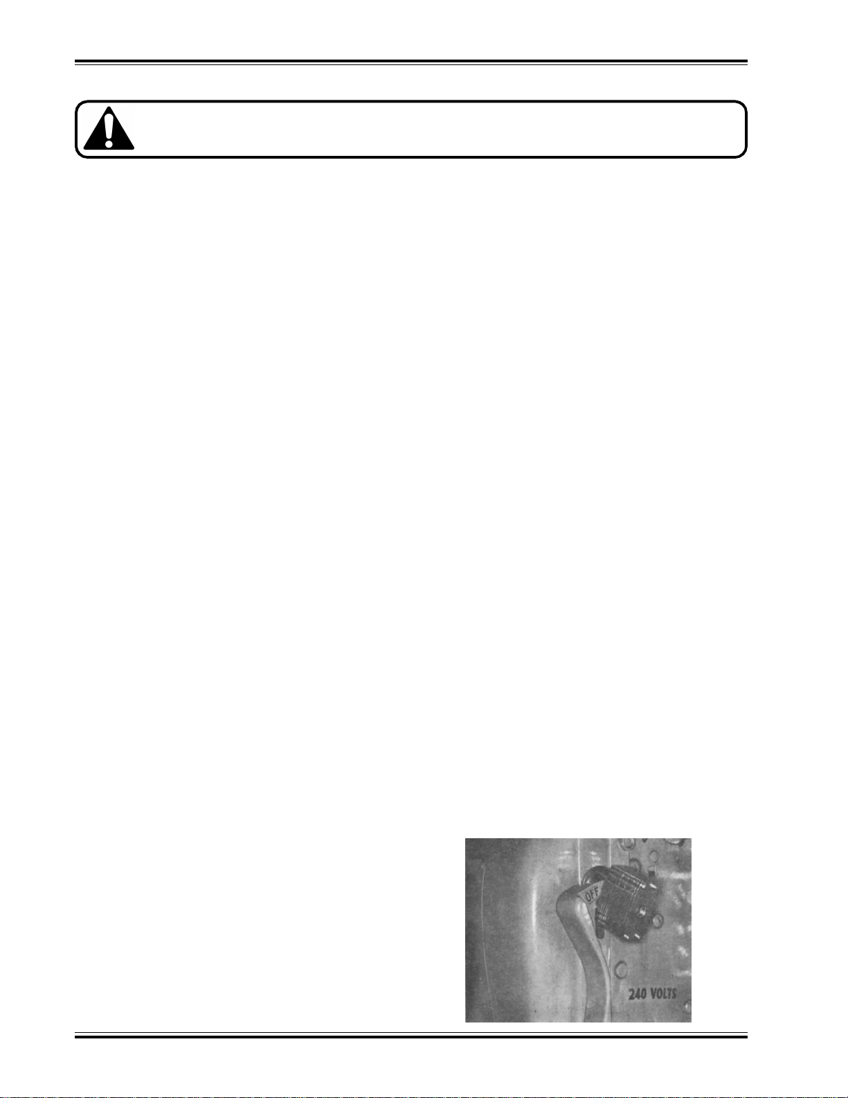
CAUTION: POWER LOCK-OUT PROCEDURE
For maximum safety when making adjustments or
repairs to your machine, be sure to lock out the
main power control switch to which the machine
is connected. The switch should be thrown to the
OFF position and a padlock placed in the loop. The
key should be held by the person servicing the
machine.
4
(fig. 1)
F.300-B/MS-5 DRILL/JULY 2000
Page 6

PACKING LIST
Part No. Description Qty.
Basic Machine ....................................................................1
W-105-1 Allen Wrench, 1/4” ‘T’ Handle ...............................................1
A-6588 Wrench, ‘T’ Handle Drill Drift ...............................................1
4688 Lubrication Stick, Drill Ease.................................................1
A-4950 Drill Sharpener, Hand.......................................................... 1
6564 Drill Block ...........................................................................3
45067 Backgage Filler Block Asm. (magnetic) ...............................2
45163 Spring - Drill Block ..............................................................1
8278-1 Knob...................................................................................2
Drill Head(s)-as orderedIncludes as Standard (per head)
CD-4-21/2
1
/4” (64mm) Hollow Drill .......................................................1
K-85 Drift Hole Cover ..................................................................1
SPECIFICATIONS
Drilling
Number of Drill Heads 2 to 5
Drill Bit Sizes Available
Center To Center Maximum 15” (38 cm)
Minimum Center Distance Between Heads 17/8” (8.7 cm)
Maximum Drilling Capacity (Pile Height) 21/2” (63 mm)
Strokes per Minute (Adjustable) Up to 18
Backgage Adjustment 0 to 5” (0 to 13 cm)
Vertical Adjustment of Individual Heads
Dimensions
Table 173/4” x 34” (45 cm x 86.4 cm)
Table Height 37” (94 cm)
Overall Height 56” (142 cm)
Floor Space Needed 36” x 36” (92 cm x 92 cm)
Net Weight (Approximate) 830 lbs (373.5 kg)
Shipping Weight (Approximate) 1000 lbs (453.6 kg)
Electrical
208/230 Volts (±10%)/18 Amps, 1 Phase, 60 Hz, AC. Service size 30 Amps.
Pump: 1/2 H.P. Spindle: 11/2 H.P.
Optional Motor: 208/230 Volts (±10%)/10 Amps, 3 Phase, AC. Service size 20 Amps.
460 Volts (±10%)/5 Amps, 3 Phase, AC. Service size 15 Amps.
Sound Emission
A-weighted sound pressure level measured in an enclosed room at 6 feet (183 cm)
above floor:
Machine running: Less than 70 dB
Machine drilling paper: 71 dB
1
/8” to 1/2” (3 mm to 13 mm)
1
/4” (6mm)
Challenge reserves the right to make changes to any product or specification without notice and without
incurring responsibility to existing units.
F.300-B/MS-5 DRILL/JULY 2000
5
Page 7

WARNING LABEL DEFINITIONS
SINGLE OPERATOR
SHOCK HAZARD
SHOCK HAZARD
Do not operate with more than one person.
Disconnect power before removing cover. Replace
cover before operation.
Disconnect power before removing cover. Replace
cover before operation.
HAZARDOUS AREA
6
Disconnect power before cleaning, servicing, or making adjustments not requiring power. Do not alter safety
guards or devices, they are for your protection. Replace all guards, do not operate with any guards removed.
F.300-B/MS-5 DRILL/JULY 2000
Page 8
INSTALLATION
Power Panel
NOTE: All guards and instruction plates are installed for your safety and information and must
remain on the machine as shipped from the factory.
Unpacking
Unless otherwise specified, this machine is packaged
completely assembled. The drill head(s) specified on
the order are shipped already installed. The machine
should be unpacked carefully by removing the packaging materials without damaging any of the machine
parts.
Immediately after uncrating, check off parts received
against the packing list. Also, examine for any physical signs of damage incurred during shipment. The
machine is inspected before and after crating at our
plant. The responsibility for filing a claim against the
carrier for damages incurred during shipment rests with
the receiver of the goods (FOB our factory).
The machine is held in place on its shipping skid with
plastic strapping material. The machine weighs approximately 850 lbs. (380 kg.), so be sure you have
sufficient equipment and manpower to handle the machine safely. Contact your Authorized Challenge Dealer
to arrange for installation.
Remove the protective coating of light oil from the
machined surfaces with a cleaning solvent, such as
type wash. Clean all other surfaces with a solvent such
as C.R.C.
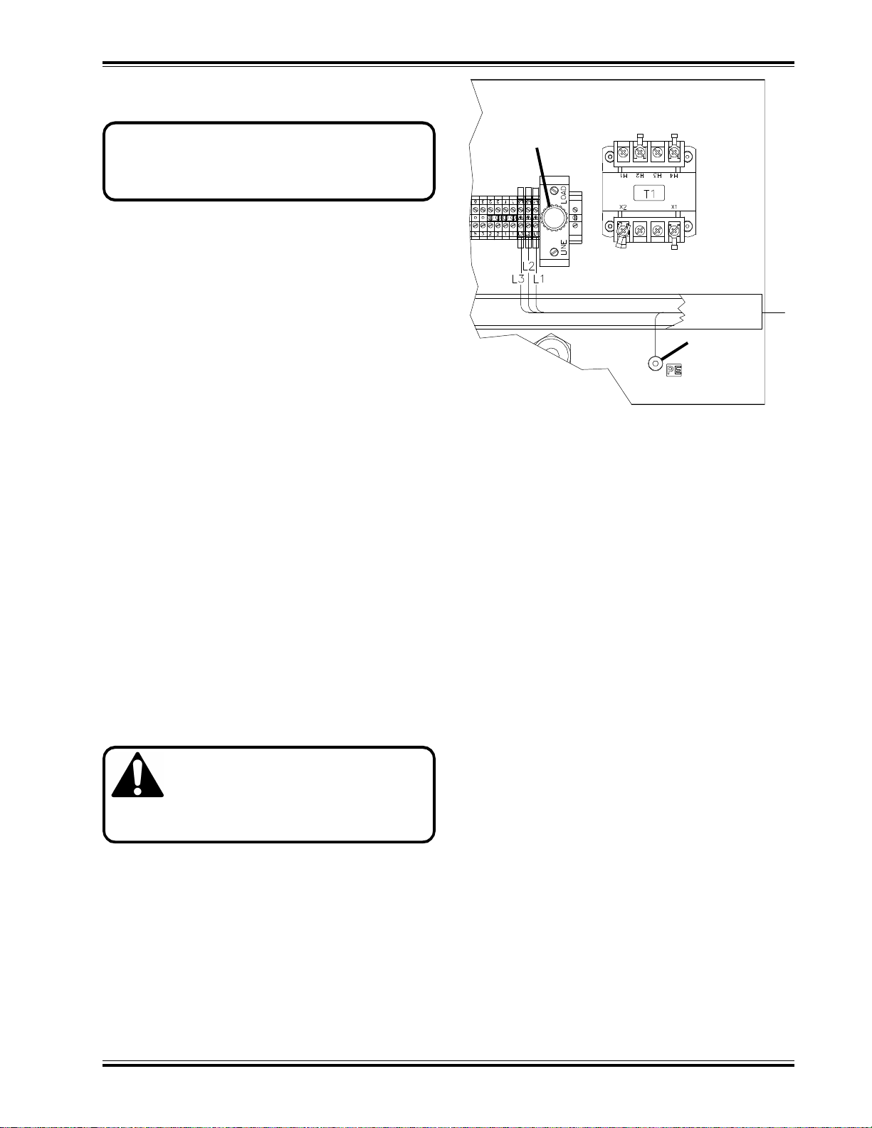
Power Hookup
WARNING: DISCONNECT POWER before cleaning, lubricating, servicing, or
making adjustments not requiring
power. Lock the disconnect switch in the OFF
position (see Power Lockout Procedure, pg. 4).
Fuse
Ground
(fig. 2)
and wired with #10 gauge wire. Optional three phase
motors are available also; 230/208 three phase, 20 amp
circuit, #12 GA. wire; and 460 volt three phase, 15 amp
circuit, with #14 GA. wire.
Remove the lower front cover. Remove the knockout
plug on the right side of the machine. Route the power
cord through the knockout hole and secure using a
conduit connector. Connect wire leads to terminals as
shown in fig 2 (single phase use L1 and L2 only). Connect the ground lead to the power panel as shown.
Replace the front cover.
On three phase machines, check to see that the motor
turns in the proper direction. Briefly turn the machine
on and off then look at the belt. If it turns in the opposite direction of the arrow on top of the motor, disconnect power to the machine and switch the connection
of any one wire with another. Check the rotation of the
motor again to be sure it turns in the proper direction.
SETUP INSTRUCTIONS
The machine is factory wired to the customer’s specification. It is the customer’s responsibility to wire the
motor for the current and voltage specified on the name
plate. It is important that the line voltage specified be
maintained. Failure to do so will result in improper operation of the machine (see trouble shooting section
for specific problems). It may be necessary to provide
a dedicated line for the machine.
The standard motor for this machine is a 208/230 single
phase. This machine should be on a 30 amp circuit
F.300-B/MS-5 DRILL/JULY 2000
Starting the Machine
The power for this machine is supplied by two motors;
one is for the hydraulic power pack and the other is for
the spindle. The hydraulic motor drives the pump directly while the spindle motor drives the drill heads.
The two motors are started and stopped simultaneously
by “on” and “off” push-buttons located on the control
panel (the main disconnect switch must be in the “on”
position, see fig. 3). The on button has a collar guard
to reduce the possibility of accidental contact. Be sure
both motors are operating before trying to drill paper.
7
Page 9
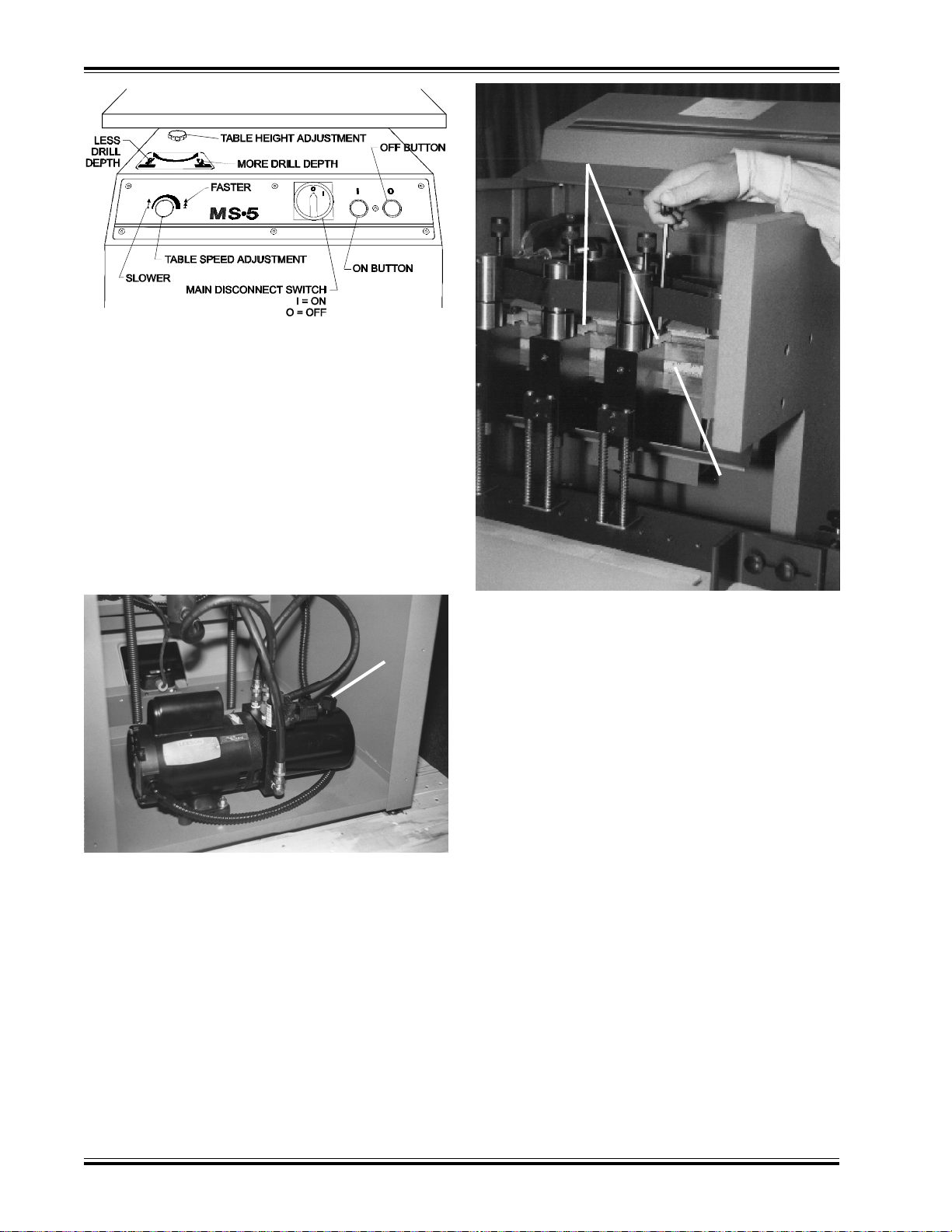
(fig. 3)
Safety Interlock System
The MS-5 paper drill is equipped with a safety interlock system which prevents the machine from being
started with the front cover open or the optional drill
guard removed. If the cover is opened or the guard
removed when the drill is in operation, the motors will
shut off and must be restarted when the cover and
guard are back in place. This is a safety feature provided to prevent accidental contact with moving parts
and must not be tampered with.
Hydraulic Check
Dovetail
Clamps
Scale
(reads from out-
side edge of head)
Dipstick
Cap
(fig. 4)
Check the hydraulic oil supply for the proper level. This
check is made by removing the rear panel and unscrewing the dip stick located on the hydraulic tank (fig. 4).
The oil level should be no higher than ½” (13 mm) up
from the bottom of the dip stick to allow room for expansion of the oil when running. Recommended oils
and a cross-reference chart are found in the maintenance section of this manual.
Positioning Drill Heads
Drill heads ordered with your machine have been installed at the factory. One ¼” drill is supplied as standard equipment with each head unless otherwise speci-
(fig. 5)
fied. The MS-5 handles two to five drilling heads
mounted on a dovetail. Each head is independently
adjustable allowing a minimum center-to-center distance of 17/8" (47.6 cm) to a maximum center-to-center
distance of 15" (381 mm). NOTE: Any number of
heads (up to five) or combination of drill hole sizes
can be drilled at one time. However, when using
½” (13 mm) drills, it is recommended that no more
than three heads be used at the same time.
Always position heads so that the lift of paper being
drilled is centered on the table. Drill heads are mounted
on a dovetail and positioned by a scale mounted on
the front of the dovetail (fig. 5).
To move heads: raise the front cover and release the
drive belt tension by lifting the belt lever. Loosen the
socket head screws holding the head to the dovetail
and position the heads according to the scale (fig. 5).
The dovetail scale is calibrated from the center of the
table and is setup to give readings to the center of the
holes. The scale is read from the outside edge of the
drill heads. (Heads mounted to the right of center read
the scale from the right side, heads to the left of center
are read to the left of the head.) Once the heads are in
the desired position, tighten the socket head screws in
the dovetail.
8
F.300-B/MS-5 DRILL/JULY 2000
Page 10
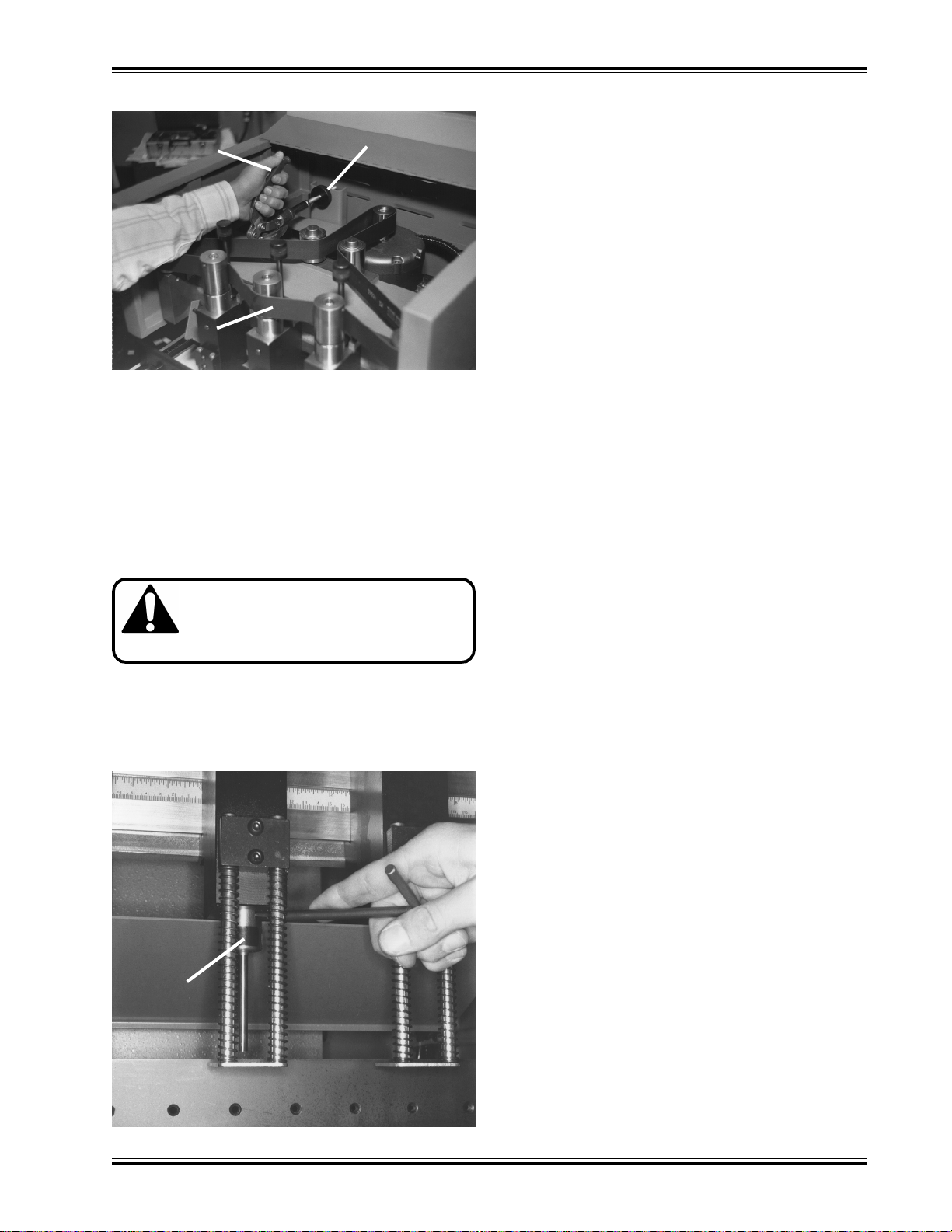
Drive Belt Adjustment
ers (black bands) are in place before operation (fig. 7).
Drive Belt
Adjusting
Lever
Drive Belt
Knurled Nut
(fig. 6)
Whenever changing head configurations or repositioning heads, reset the drill head belt tension. This is
done by backing off the knurled adjusting nut (fig. 6)
with the belt lever in the up position. Lower the lever
and turn the knurled nut out until it is tight. Raise the
lever and turn the knurled nut out an additional 1½ to 2
turns. Lower the lever and close the front cover.
Drill Installation
CAUTION: Always handle drills with
care to avoid severe lacerations. Even
dull drills are sharp enough to cause
lacerations.
Insert the tapered head of the hollow drills into the
spindles. Press the drills firmly into place so they do
not fall out when the motor is first started. To prevent
drill chips from flying out be sure that the drift hole cov-
Make sure the cutting stick blocks are in position before trying to drill paper.
Drill Removal
After use, drills may become seated making it difficult
to remove them. Use the T-handled drill drift tool to
free stuck drills. Uncover the drill drift hole by sliding
the cover down. Insert the drill drift with the flat edge
down and lift up to force the drill out of the head (fig. 7).
Stroke Adjustment (Table Height Adjustment)
Whenever installing new or resharpened drills, the table
stroke and drill height must be adjusted. Turn in (clockwise) the table height adjustment to lower the table
(fig. 3). Next, lift the front cover and back off the drill
head adjustment on each head. Place a single sheet
of paper under the drills and raise the table with the
foot treadle. Gradually raise the table height by turning the table height knob out (counter clockwise) and
pressing the foot treadle to check the table height.
Continue to do this until the first drill cuts through the
paper. Once the table height has been set, adjust the
drill heads individually until all the drills now cut through
the paper. When cutting full lifts, any further stroke
adjustment can now be made with the table height adjustment knob.
Note: The MS-5 uses 2” and 21/2” long drills. Be sure
to adjust the table stroke and/or drill height accordingly
when changing from one drill length to another.
Adjusting the Stroke Speed
Drift Hole
Cover
F.300-B/MS-5 DRILL/JULY 2000
(fig. 7)
The hydraulic unit is equipped with an adjustable valve
for regulating the table stroke speed (up and down
travel). Maximum speed is 18 strokes per minute which
is the speed used on the average run of work. Soft
stocks such as mimeographs, NCR, etc., are apt to
wrinkle at high speeds, and the speed should be regulated to a point where the best results are obtained.
This is found mostly by “trial and error.”
This adjustment is made by turning the adjustable valve
(located on the left side of the control panel) counterclockwise to reduce speed and clockwise to increase
speed.
Never turn the speed control knob more than 2½ turns
counterclockwise (slow speed) as the drill will not bottom and engage the return cycle. Less than one turn
counterclockwise should suffice for all drilling operations. Slow speeds may also cause the drills to “burn”
through the paper. If burning occurs, either increase
9
Page 11
the vertical speed, sharpen the drills or check for proper
belt tension.
Slower vertical speeds are recommended when drilling with the maximum number of heads.
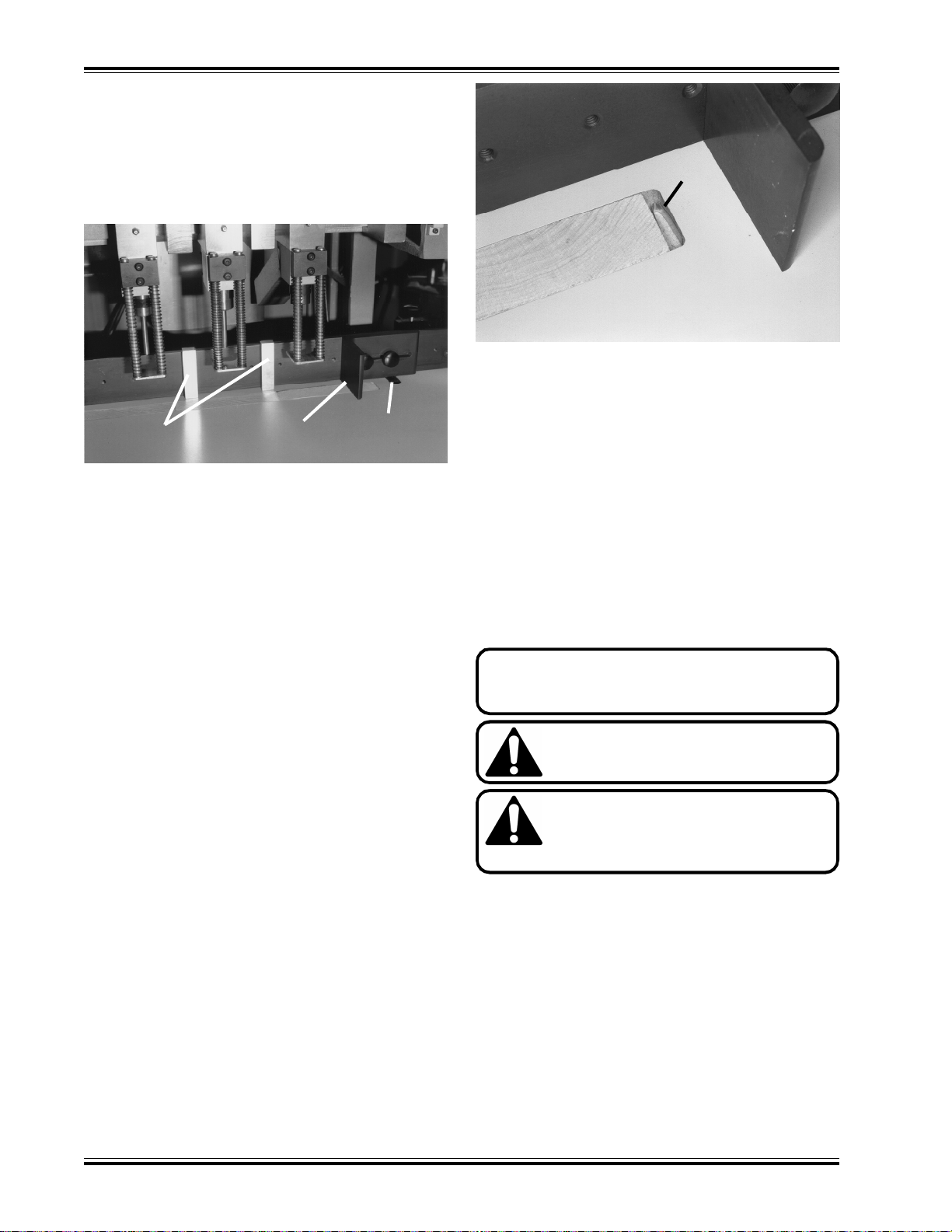
Setting Up the Backgage
Filler Blocks Side Guide
Scales are provided in the table for setting up the backgage. The scales read in inches/mm and will give you
the dimension from the back of the sheet to the
centerline of the holes. Two magnetic filler blocks are
provided if it is necessary to drill within 1" of the edge
of the sheet, fig. 8. The blocks are ½” (13 mm) thick
and when used, ½” (13 mm) must be subtracted from
the scale reading to give the set up dimension. Example: To drill 3/4" (19 mm) from the edge of the sheet,
install the filler blocks and set the backgage to 1¼” (32
mm) on the scale.
Using the Side Guide(s)
The adjustment for the location of the holes to the top
or bottom edge of the sheet is provided by a sturdy
side guide. The backgage has a series of threaded
holes to which the side guide is attached with two
threaded knobs. In addition, the side guide is slotted
to fine adjust the position of the paper. When setting
up drill head positions and side guides, always try to
keep the paper centered on the table as much as possible.
Two side guides are provided as standard equipment
so stock may be drilled to the left or right or for setting
up multiple drilling sequences for more than five holes.
Drill Blocks
Place the drill blocks in the slot in the table. They are
held tightly in place by pinching the drill block spring
and placing it in the slot in the table at the end of the
drill blocks (fig 9).
Table
Scale
(fig. 8)
Spring
Drill Block
(fig. 9)
The drill blocks are removed by simply lifting them from
their groove in the table. They should set flush with
the table and may be shimmed if necessary. For best
use and longest life, turn them end for end, top and
bottom.
Emptying the Drill Chips
A large capacity chip bag attached to the rear of the
machine, can be easily taken off and emptied by slipping it off the two hooks provided.
OPERATION
For EMERGENCY STOP release foot from
treadle and turn main disconnect switch to “off”
position.
CAUTION: NEVER REST YOUR FOOT
ON THE TREADLE WITHOUT INTENDING TO BRING UP THE TABLE.
CAUTION: NEVER PUT HANDS OR
FINGERS NEAR DRILL HEADS WHEN
OPERATION THE MACHINE. SEVERE
LACERATIONS COULD RESULT.
Pressing the foot treadle activates the hydraulic unit
bringing the table and stock up to the drills and returning back again automatically. The pedal must be released and depressed again before the next drill cycle
assuring full control and allowing no repeat stroke.
Releasing the pedal at any time stops the table movement and returns it to its normal down position, thus
preventing costly errors.
The vertical movement of the table is actuated by the
hydraulic unit. Depressing the foot treadle sets the
hydraulic unit into action. Keeping your foot on the
10
F.300-B/MS-5 DRILL/JULY 2000
Page 12

treadle allows the drills to drill through the entire lift of
stock and reach the bottom of their stroke. At this point,
the solenoid is de-energized and the valve released,
relieving the pressure off of the cylinder and allowing
the table to return to the down position.
DRILLING TIPS
Important! To prevent the drill from overheating, always avoid drilling too slowly. The table should be brought
up as rapidly as possible allowing the drills to easily cut through the paper. Also, adjust the vertical table guide to
return the table to the down position as rapidly as possible to avoid spinning the drills in the stock.
Slotted Holes - Instead of punching slotted holes for five and seven hole universal binding work, save time and
cost by drilling a 1/2 inch diameter hole in place of the slot. The slot is only intended to allow the post or ring to be
used in either location, and the large hole permits this.
Plastic Bindings - Drilling holes for plastic bindings, instead of punching them, is practical and saves a great
deal of time, particularly on long run jobs.
Keep Drills Sharp - A dull drill is the major cause of drill breakage and production tie-ups. Usually after three
hours of drilling, depending on the type of paper being processed, the drill should be sharpened. A dull drill
results in poor quality work.
Keep Drills Clean - A dirty and rusty drill will not permit the free upward passage of the drill chips. Pressure built
up by a clogged drill will split or break the drill. To keep it free from dirt or rust, clean the drill of all chips after each
use and apply a light oil to the inside and outside. Drills should be cleaned out immediately after each use. This
is particularly true if a coated or varnished stock has been drilled. On these jobs the coating on the chips
frequently fuse the chips into one solid mass when the drill cools, causing breakage the next time the drill is used.
Lubricate Drills - Lubrication assists in the passage of the chips and helps avoid overheating of the drills. Use
readily available stick lubricants for this purpose. Hold the end of the stick against the side of the rotating drill. Be
sure to touch the cutting edge with the lubricant also. Wipe off excess oil before drilling. CARE MUST ALWAYS
BE TAKEN WHEN HANDLING DRILLS.
Keep Spindle Clean - Clean out the drill spindle frequently. This will prevent any buildup in the spindle of the
drill.
Set the Drills Correctly - Do not cut too deeply into the cutting block. The drill should just touch the block and
cleanly cut through the bottom sheet. During drilling, do not set the drill deeper into the block but change the
position of the block frequently. Drilling deeper into the block dulls the drills quickly. Use a piece of chipboard
underneath your stock. This will make handling the stock easier and will ensure that the last sheet is cut cleanly
through.
Check for Drill Wobble - If spindles are badly worn or bent through misadjustment, have them replaced immediately. A wobbly or loosely held drill will break.
Check Your Drill Sharpener - The cutting edge of the sharpening bit should be inspected frequently to make
certain that it is sharp and free of nicks. Never let a drill drop onto the sharpening bit. It will chip the sharpening
edge. Use gentle pressure when sharpening - let the sharpening bit do the work. Check the sharpness of the drill
after sharpening. The cutting edge should be razor sharp.
Just a little time and effort taken with each use of your paper drilling machine should result in trouble free operation over many years.
F.300-B/MS-5 DRILL/JULY 2000
11
Page 13
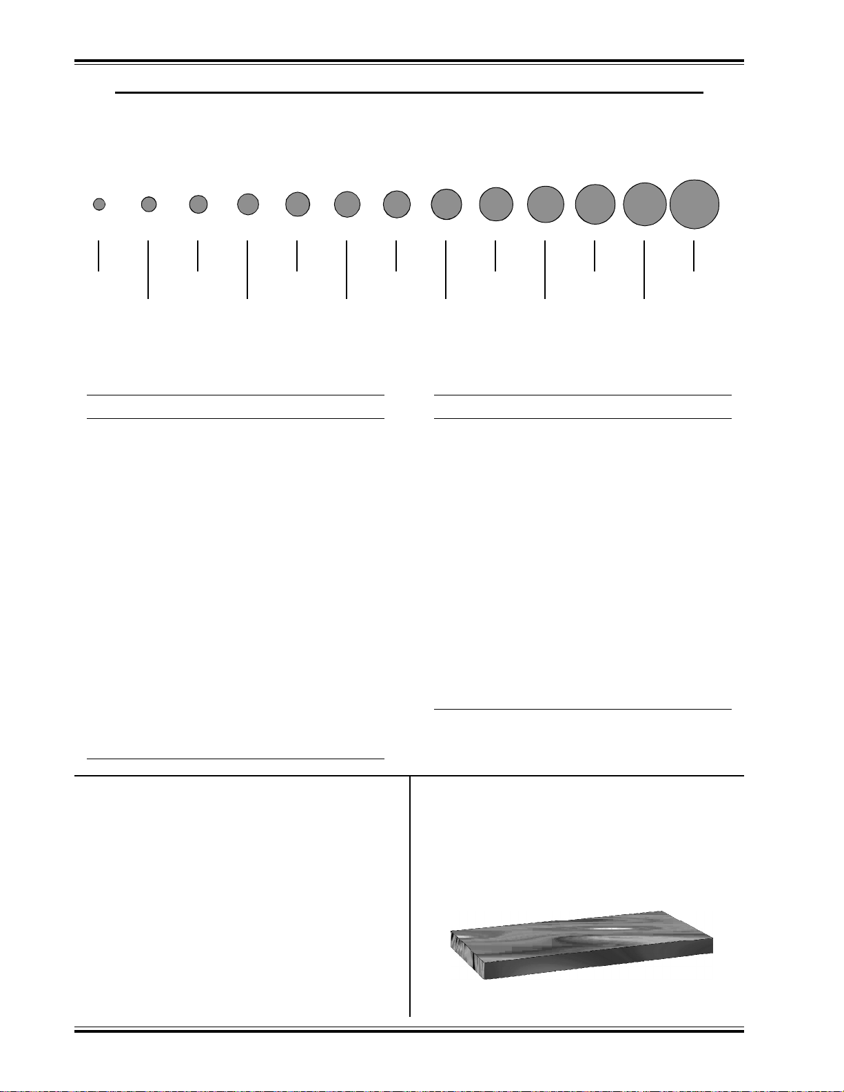
ACCESSORIES FOR CHALLENGE PAPER DRILLING MACHINES
Genuine Challenge Hollow Drills
In 13 Standard Sizes For Every Drilling Need
1/8” 3/16” 1/4” 9/32”
5/32” 7/32”
17
/64” 5/16” 3/8” 7/16”
11
/32”
13
/32” 1/2”
All drills carried in stock by local Challenge dealers (17/32” & 9/16” available by special order).
HOLLOW DRILLS
Diameter x Drill Capacity Cat. No.
1
/8” x 5/8” (3.2 x 16 mm) ................... CD-2-3
5
/32” x 11/8” (4 x 29 mm) ................... CD-52
3
/16” x 15/8“ (4.8 x 41 mm) ................ CD-3
7
/32” x 2” (5.6 x 51 mm) ................... CD-72
1
/4” x 2” (6.3 x 51 mm)..................... CD-4
1
/4” x 21/2” (6.3 x 63.5 mm)............... CD-4-21/2
17
/64” x 2” (6.7 x 51 mm) .................. CD-174
9
/32” x 2” (7.1 x 51 mm) ................... CD-92
5
/16” x 2” (7.9 x 51 mm) ................... CD-5
5
/16” x 21/2” (7.9 x 63.5 mm) ............. CD-5-21/2
11
/32” x 2” (8.7 x 51 mm) .................. CD-112
3
/8” x 2” (9.5 x 51 mm)..................... CD-6
3
/8” x 21/2” (9.5 x 63.5 mm)............... CD-6-21/2
13
/32” x 2” (10.3 x 51 mm) ................ CD-132
7
/16” x 2” (11.1 x 51 mm).................. CD-7
1
/2” x 2” (12.7 x 51 mm)................... CD-8
1
/2” x 21/2” (12.7 x 63.5 mm)............. CD-8-21/2
TEFLON COATED HOLLOW DRILLS
Diameter x Drill Capacity Cat. No.
1
/8” x 5/8” (3.2 x 16 mm) ................... TCD-2-3
5
/32” x 11/8” (4 x 29 mm) ................... TCD-52
3
/16” x 15/8“ (4.8 x 41 mm) ................ TCD-3
7
/32” x 2” (5.6 x 51 mm) ................... TCD-72
1
/4” x 2” (6.3 x 51 mm)..................... TCD-4
1
/4” x 21/2” (6.3 x 63.5 mm)............... TCD-4-21/2
17
/64” x 2” (6.7 x 51 mm) .................. TCD-174
9
/32” x 2” (7.1 x 51 mm) ................... TCD-92
5
/16” x 2” (7.9 x 51 mm) ................... TCD-5
5
/16” x 21/2” (7.9 x 63.5 mm) ............. TCD-5-21/2
11
/32” x 2” (8.7 x 51 mm) .................. TCD-112
3
/8” x 2” (9.5 x 51 mm)..................... TCD-6
3
/8” x 21/2” (9.5 x 63.5 mm)............... TCD-6-21/2
13
/32” x 2” (10.3 x 51 mm) ................ TCD-132
7
/16” x 2” (11.1 x 51 mm).................. TCD-7
1
/2” x 2” (12.7 x 51 mm)................... TCD-8
1
/2” x 21/2” (12.7 x 63.5 mm)............. TCD-8-21/2
Special order drills
17
/32” x 2” (13.5 x 51 mm) ................ CD-172
9
/16” x 2” (14.3 x 51 mm).................. CD-9
Challenge Drill-Ease Lubricant
Stick
Cat. No. 4688
This lubricating stick provides a dry stainless lubricant
which has many uses throughout the printing plant. It
is specially recommended for use on hollow drills for
easier drilling, particularly when drilling clay coated
stock. It eliminates binding and excessive heating of
the drill. Will not discolor the stock.
CARE MUST ALWAYS BE TAKEN WHEN USING
STICK AND HANDLING DRILLS.
12
Challenge Drilling Blocks
Cat. No. A-6626-24
These Challenge 11/4 x 6” End-Wood Drilling Blocks
are for round hole drilling operations. Sold in packages of 24.
F.300-B/MS-5 DRILL/JULY 2000
Page 14
ACCESSORIES FOR CHALLENGE PAPER DRILLING MACHINES
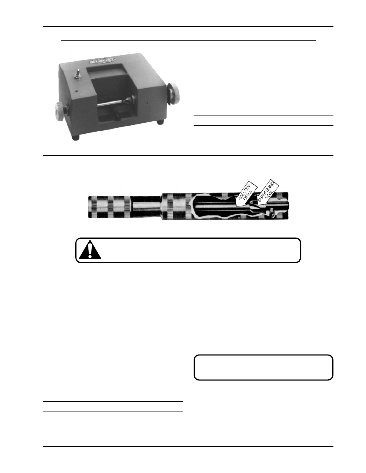
Challenge Power Sharpener
(115 Volt / 60 HZ only)
Cat. No. A-6450
A power drill sharpener. Plugs into any standard 115
volt, 60 cycle, AC outlet. Handles Challenge and other
taper shank drills. Adaptors also available for handling
practically all other makes.
Item Cat. No.
Replacement Cutting Bit 6469
Resharpening Service - Your Old Bit 6469-R
HOLLOW DRILL SHARPENER For fast, easy drill sharpening
CAUTION: Drills are sharp even after use. Be careful to keep edge
away from your body. To prevent personal injury and/or damage to
the drill, ALWAYS keep drills in protected area.
Here’s a unit that really makes drill sharpening easy.
All you do is place the hollow drill in the tapered end of
the drill holder, insert the unit on the cylinder, then turn
two or three times...and you have a perfectly sharpened drill.
This Challenge Hollow Drill Sharpener can pay for itself many times over through longer drill life, easier,
faster drilling, and less sharpening time. All sizes of
drills from 1/8 to 1/2 inch in diameter can be sharpened.
The drill sharpener automatically puts just the right
amount of bevel on the hollow drill for the best drilling
results. It’s self centering, too, so that the center of the
sharpening bit exactly meets the center of the hollow
drill. The drill sharpener also has a replaceable sharpening bit.
Item Cat. No.
Challenge Hollow Drill Sharpener A-4950
Extra Cutting Bit 4952
Instructions:
NOTE: Always handle carefully
1. Be sure to wipe off all grease before using the
sharpener.
2. Remove any paper chips from the hollow drill.
3. Place the hollow drill in the drill holder section.
Insert the sharpening section, being very careful
to bring the drill and cutting tool together without
bumping.
NOTE: The cutting tool is made of a glass hard
material and may be chipped by careless handling.
4. Turn the cutting unit clockwise, maintaining an even
pressure until the hollow drill is sharpened (usually two or three turns). The cutting tool seldom
requires regrinding, but when it does, the bit should
be sent to the factory as regrinding must be done
on a diamond wheel.
F.300-B/MS-5 DRILL/JULY 2000
13
Page 15
ACCESSORIES FOR CHALLENGE PAPER DRILLING MACHINES
Optional Narrow Drill Head Assembly, p/n: 45200
For drilling holes with a center to center distance as low as 1-3/8”/3.5 cm
14
F.300-B/MS-5 DRILL/JULY 2000
Page 16

NOTICE
The instructions on the
following pages are for the
use of trained service
personnel only!
Attempting to perform
repair and replacement
procedures without proper
training may cause machine
damage or operator injury!
PARTS CUSTOMERS: The Challenge Machinery Company provides parts with the express understanding that they are to replace parts found missing or no longer serviceable on equipment designed
and/or manufactured by Challenge. The Challenge Machinery Company assumes no liability for any
modification or alteration to any Challenge products, and any such modification or alteration to any
Challenge products is not authorized by The Challenge Machinery Company. Any modification or
alteration of any Challenge product will void any remaining warranty.
F.300-B/MS-5 DRILL/JULY 2000
15
Page 17

TROUBLESHOOTING
WARNING: DISCONNECT THE POWER AND LOCK IT OUT whenever working on the machine
unless the instructions specifically require the machine to be powered (see Power Lockout
Procedure, page 4). Several of the following tests may require the machine to be operational
for checking and adjusting. Be very careful that tools and other people are clear of moving parts, and
that the drill is not accidentally operated while adjustments are being made.
CAUTION: Whenever repairing hydraulic components, loosen connections slowly to bleed
off any trapped pressure.
Problem Area to Check Solution
1. No power Power to machine Connect Power
Main Disconnect Switch Turn to ON position
Interlocking Guards Replace guards
Fuse blown Replace fuse - see fig. 2 page 7
2. Lack of power Relief valve in pump may be bad Clean or replace relief valve or pump.
or have dirt in it.
Check oil level - may be low. Add oil.
Check voltage at machine - may Remove other machinery on line or
be low. provide a dedicated line.
3. Spindle motor stalls Dull drills. Sharpen drills.
Check for low voltage. (See above).
Check drive pulley and belt for (See SETUP INSTRUCTIONS in main
tightness. section for adjustment).
Check for paper plugging drills Clean out hollow drills - We recom-
mend cleaning and soaking drills in
oil overnight.
4. Table stroke won’t adjust Stroke Adjustment Chain off Remove back panel and replace
sprockets. chain (fig. 10).
16
Table Lift Rod
(fig. 10)
F.300-B/MS-5 DRILL/JULY 2000
Page 18

ROUTINE MAINTENANCE
General
Production losses can be reduced if good maintenance
practices are followed. The following suggestions may
be helpful:
1. Recognize the fact that the user of hydraulic equipment has more control over maintenance than the
manufacturer.
2. Operators should be familiar with use, care, and
limitations of the equipment. ALL OPERATORS
SHOULD READ THIS MANUAL COMPLETELY.
3. Use properly trained maintenance personnel.
4. Establish a program of systematic preventative
care for your equipment or put this machine on an
existing preventative maintenance program.
5. Analyze and isolate trouble before having any part
of the equipment dismantled.
Lock Nut
6. Be aware of how your machine should sound and
perform. If the machine is not operating properly
or if it doesn’t “sound right”, stop running your job
immediately and try to identify the problem.
7. Call the dealer for any problems that cannot be
handled by your own personnel.
Vertical Table Guide
CAUTION: PINCH POINT. This adjustment requires a guard to be removed
for adjustment and testing purposes
only. Be very careful while adjusting. Replace
all guards before operating. Do not operate
machine with any guards removed.
The vertical table guide is located on the right side of
the machine beneath the table and may need periodic
adjustment to keep the table steady yet allow it and
stock to fall away from the drills as rapidly as possible.
The table down stroke is controlled by a return spring.
Remove the guide block cover guard. Tighten the two
guide block lock nuts (fig. 11) and power the table up
by pressing the foot treadle. Gradually back the locknuts off evenly until the table releases freely. Retest
the upstroke and table return, and check the table for
side play. Replace the guard.
CAUTION: PINCH POINT.
Replace guard after adjusting.
(fig. 11)
SERVICE CHECKLIST
Daily
1. Keep drills sharp!
2. Lubricate the hollow drill frequently with the lubricating stick provided.
3. For better hollow drill life, remove the drills when
not in use and soak in light oil. Wipe off excess oil
before drilling.
4. Wipe off excess grease from the drill heads and
idlers.
Weekly (or every 40 hours of operation)
1. Check belt wear/tension.
2. Oil the table lift rod between the table and stand
with light oil (fig. 10).
F.300-B/MS-5 DRILL/JULY 2000
17
Page 19

Monthly
1. Oil the table height adjusting knob shaft with a light
machine oil. Wipe off excess oil.
2. Check the hydraulic oil supply for the proper level.
This check is made by removing the rear panel
and removing the dip stick/plug (pg. 8, fig. 3). The
oil should be visible on the dip stick but no higher
than 1/2“ up from the bottom when cool. This allows for expansion of the oil when hot. Use only
one of the recommended oils or an ISO VG 100
Hydraulic Fluid equivalent. Oils other than the recommended type will cause seals, cups and O-rings
to deteriorate. See Chart & CAUTION.
Yearly
1. Check all adjustments.
2. Tighten all screws.
3. Change hydraulic oil in reservoir. Oil may have to
be changed more often if contamination of any kind
gets in the oil.
Super Hydraulic 100 Conoco
Nuto H-100 Exxon
Harmony 100 AW Gulf
HO 2A Hydraulic Oil Lubriplate
DTE No. 18 Mobil
Pennzoil AW 100 Pennzoil
Magnus A Oil 215 Phillips
Tellus 100 Shell
Energol HLP 100 Sohio
Industron 100 Std. Oil Indiana/Boron
Sunvis 851 WR Sunoco
Rando HD 100 Texaco
Unax AW 100 Union Oil Co.
Hydraulic
Through normal use, hydraulic systems gum up and
seals wear. Signs of wear are hydraulic leaks and erratic operation of the vertical speed. Check with your
Authorized Challenge Dealer for a current repair and/
or replacement policy.
Drill Heads
Through normal use, bearings will wear and need replacing. Signs of wear are excessive noise, heat, or
loose spindles.
CAUTION: NEVER USE Automatic
Transmission oil or brake fluid as a
substitute! Oils other than the recommended type will cause seals, cups and O-rings
to deteriorate. Unsafe operating conditions will
result.
Recommended Oils
Oil Name Distributor
Rykon No. 100 AMOCO
Duro AW Oil 465 Arco
AW Machine Oil 100 Chevron
Pacemaker XD No. 100 Citgo
18
F.300-B/MS-5 DRILL/JULY 2000
Page 20

NOTES
F.300-B/MS-5 DRILL/JULY 2000
19
Page 21

MAIN ASSEMBLY - FRONT VIEW
45000 SHEET 1 REV L
20
F.300-B/MS-5 DRILL/JULY 2000
Page 22

MAIN ASSEMBLY - FRONT VIEW
45000 SHEET 1 REV L
F.300-B/MS-5 DRILL/JULY 2000
21
Page 23

MAIN ASSEMBLY - SIDE VIEW
45000 SHEET 2 REV K (S/N 975272 & BELOW)
22
F.300-B/MS-5 DRILL/JULY 2000
Page 24

MAIN ASSEMBLY - SIDE VIEW
45000 SHEET 2 REV K (S/N 975272 & BELOW)
F.300-B/MS-5 DRILL/JULY 2000
23
Page 25

MAIN ASSEMBLY - SIDE VIEW
45000 SHEET 2 REV L (S/N 975273 & ABOVE)
24
F.300-B/MS-5 DRILL/JULY 2000
Page 26
MAIN ASSEMBLY - SIDE VIEW
45000 SHEET 2 REV L (S/N 975272 & ABOVE)
F.300-B/MS-5 DRILL/JULY 2000
25
Page 27

MAIN ASSEMBLY- TOP VIEW
45000 SHEET 3 REV F (S/N 985049 and Down)
26
F.300-B/MS-5 DRILL/JULY 2000
Page 28

MAIN ASSEMBLY- TOP VIEW
45000 SHEET 3 REV G (S/N 985050 and Up)
F.300-B/MS-5 DRILL/JULY 2000
27
Page 29

(KIT FOR 60 HZ MACHINES: K-45180)
45000 SHEET 4 REV A (S/N: 975272 & BELOW)
MAIN ASSEMBLY - DRILL GUARD (50 HZ ONLY)
28
F.300-B/MS-5 DRILL/JULY 2000
Page 30

45000 SHEET 4 REV C (S/N: 975273 & ABOVE)
(KIT FOR 60 HZ MACHINES: K-45180)
MAIN ASSEMBLY - DRILL GUARD (50 HZ ONLY)
F.300-B/MS-5 DRILL/JULY 2000
29
Page 31

BELT INSTALLATION
30
F.300-B/MS-5 DRILL/JULY 2000
Page 32

NOTES
F.300-B/MS-5 DRILL/JULY 2000
31
Page 33

HYDRAULIC POWER UNIT ASSEMBLY
H-378-1 (50/60 HZ 1 PHASE)
H-407-1 (50/60 HZ 3 PHASE)
32
F.300-B/MS-5 DRILL/JULY 2000
Page 34

HYDRAULIC SEQUENCE OF OPERATION
NOTE: PLEASE SEE SECTION ON THE ELECTRICAL SEQUENCE OF OPERATION FOR MORE
DETAILS
HYDRAULIC SEQUENCE OF OPERATION
A. Pump relay is energized providing power to the
hydraulic motor.
B. Energize the UP solenoid (the table is sent up).
C. De-energize the UP solenoid (the table is sent
down).
HYDRAULIC SCHEMATIC REFERENCES
(Drawing H-378 & H-407)
Once the pump relay (RL1) is energized, the hydraulic
motor runs with the UP solenoid de-energized. This
allows oil to flow through the UP solenoid valve (Item
#6) and back to the tank. The table remains in the
down position.
When the UP solenoid is energized, oil stops flowing
through the UP solenoid valve (Item #6), and flows to
the table up (TU) port of the table speed adjustment
valve (Item #9) and to the table up (TU) port of the
cylinder. Oil exits the table speed adjustment valve
(Item #9) through the table speed (TS) port and then
returns to the tank. The amount of oil that flows through
the valve affects how much oil flows to the cylinder.
This determines the speed of the cylinder piston. As
the piston moves up, excess oil in the cylinder is forced
out the excess (EX) cylinder port and back to the tank.
When the UP solenoid is de-energized, oil from the
pump flows freely through the UP solenoid valve (Item
#6) and back to the tank. This allows oil to flow out of
the cylinder through the table up (TU) cylinder port,
through the UP solenoid valve (Item #6), and back to
the tank. Two springs force the piston down. The pump
relay (RL1) remains energized.
F.300-B/MS-5 DRILL/JULY 2000
33
Page 35

E-2384-1 REV A
BASIC MACHINE SCHEMATIC
34
F.300-B/MS-5 DRILL/JULY 2000
Page 36

ELECTRICAL SEQUENCE OF OPERATION
NOTE: PLEASE SEE SECTION ON THE HYDRAULIC SEQUENCE OF OPERATION FOR MORE
DETAILS
ELECTRICAL SEQUENCE OF OPERATION
A. Close the main disconnect switch (MD).
B. Press the ON button (START).
C. Press the foot switch (FOOTSWITCH).
ELECTRICAL SCHEMATIC REFERENCES
(Drawing E-2384-1)
While the main disconnect switch MD is closed, power
is brought to transformer T1, provided fuse F1 is conductive. Transformer T1 provides power to the hydraulic motor and spindle motor contactors RL1. The
contactors are open and therefore the motors will not
run. Opening the main disconnect switch MD at any
time cuts power to transformer T1.
When the START switch is closed, the hydraulic motor
and spindle motor relay coil RL1 will energize, provided
interlock switches S1 and S2 are closed. Power is
then supplied to the hydraulic and spindle motors. RL1
remains energized until the STOP switch or any interlock switch is opened.
While the FOOTSWITCH switch is closed, power is
brought to the UP solenoid, which raises the table.
When the table reaches the top, the TAKE UP STOP
switch closes, causing relay coil RL2 to energize. While
RL2 is energized, the UP solenoid becomes de-energized, which lowers the table. Opening the
FOOTSWITCH switch de-energizes RL2 and the UP
solenoid.
F.300-B/MS-5 DRILL/JULY 2000
35
Page 37

EE-2385-2
1PH 208/230 V 50/60 Hz
POWER PANEL ASSEMBLY
36
F.300-B/MS-5 DRILL/JULY 2000
Page 38

EE-2385-2
1PH 208/230 V 50/60 Hz
POWER PANEL ASSEMBLY
F.300-B/MS-5 DRILL/JULY 2000
37
Page 39

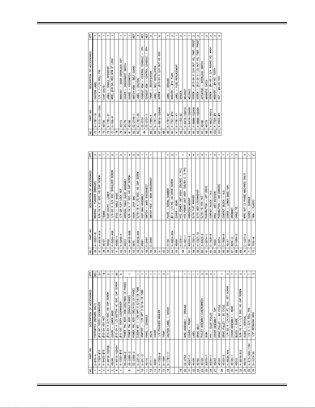
EE-2386-2
POWER PANEL ASSEMBLY
3PH 208/230V 50/60Hz/460 V 60 Hz
38
F.300-B/MS-5 DRILL/JULY 2000
Page 40

EE-2386-2
POWER PANEL ASSEMBLY
3PH 208/230V 50/60Hz/460 V 60 Hz
F.300-B/MS-5 DRILL/JULY 2000
39
Page 41

EE-2369-2
3PH 380/415 V 50 Hz
POWER PANEL ASSEMBLY
40
F.300-B/MS-5 DRILL/JULY 2000
Page 42

EE-2369-2
3PH 380/415 V 50 Hz
POWER PANEL ASSEMBLY
F.300-B/MS-5 DRILL/JULY 2000
41
Page 43

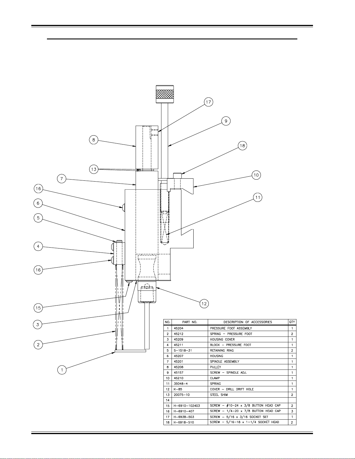
DRILL HEAD ASSEMBLY
45152
42
F.300-B/MS-5 DRILL/JULY 2000
Page 44
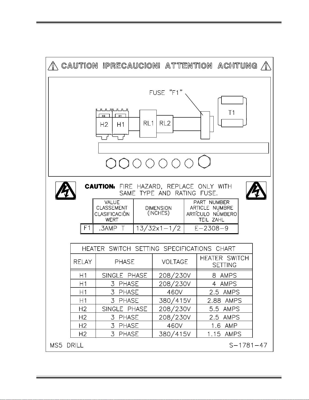
POWER PANEL LABEL
50/60 Hz REV A
F.300-B/MS-5 DRILL/JULY 2000
43
Page 45

A-4851-48
TWO HAND CONTROL OPTION
44
F.300-B/MS-5 DRILL/JULY 2000
Page 46

A-4851-48
TWO HAND CONTROL OPTION
F.300-B/MS-5 DRILL/JULY 2000
45
Page 47

K-45180 REV A
DRILL GUARD KIT
46
F.300-B/MS-5 DRILL/JULY 2000
Page 48

K-45181 (S/N: 975272 & BELOW ONLY)
BELT GUARD SWITCH REPLACEMENT KIT
F.300-B/MS-5 DRILL/JULY 2000
47
Page 49

K-45182 (S/N: 975272 & BELOW ONLY)
DRILL GUARD SWITCH REPLACEMENT KIT
48
F.300-B/MS-5 DRILL/JULY 2000
Page 50

SAFETY SYSTEM TESTS
Machine manufacturer _______________ Model ____________
Serial Number __________________
Frequency of test: THESE TESTS SHOULD BE PERFORMED AT THE BEGINNING OF EACH WORK DAY.
Connect power to the machine, turn the main disconnect switch to the “on” position, and press the “on” button.
Check both motors to see that they are operating.
Test #1:With the machine running, open the upper front cover. This should stop all motion. Close front cover.
Test #2:With the machine running, remove the front guard. This should stop all motion. Replace guard.
If the motors continue to run during either test, readjustment or repair is needed.
Please enter date and initials for both tests.
Date ______ ______ ______ ______ ______ ______ ______ ______ ______ ______ ______ ______
Test 1 ______ ______ ______ ______ ______ ______ ______ ______ ______ ______ ______ ______
Test 2 ______ ______ ______ ______ ______ ______ ______ ______ ______ ______ ______ ______
Date ______ ______ ______ ______ ______ ______ ______ ______ ______ ______ ______ ______
Test 1 ______ ______ ______ ______ ______ ______ ______ ______ ______ ______ ______ ______
Test 2 ______ ______ ______ ______ ______ ______ ______ ______ ______ ______ ______ ______
Date ______ ______ ______ ______ ______ ______ ______ ______ ______ ______ ______ ______
Test 1 ______ ______ ______ ______ ______ ______ ______ ______ ______ ______ ______ ______
Test 2 ______ ______ ______ ______ ______ ______ ______ ______ ______ ______ ______ ______
Initials of
Repairs Repairer Date
_________________________________________ ________ _____________
_________________________________________ ________ _____________
_________________________________________ ________ _____________
_________________________________________ ________ _____________
_________________________________________ ________ _____________
_________________________________________ ________ _____________
_________________________________________ ________ _____________
_________________________________________ ________ _____________
_________________________________________ ________ _____________
F.300-B/MS-5 DRILL/JULY 2000
49
Page 51

F.300-B/MS-5 DRILL/JULY 2000© 1996, 1997 by The Challenge Machinery Company. All rights reserved. Printed in the U.S.A.
Page 52

 Loading...