

Page 1

5000
BTU LOCAL AIR CONDITIONER
INSTRUCTION MANUAL
Page 2

CONTENTS
SAFETY PRECAUTIONS
Safety rules........................................................................................................................................2
Operating condition.....................................................................................................................................3
Suggested tools for window kit installation..................................................................................................3
IDENTIFICATION OF PARTS
Names of parts...................................................................................................................................4
Accessories.................................................................................................................................................4
INSTALLATION INSTRUCTIONS
Installation instruction............................................................................................................... .……..5
Exhaust hose installation………..............................................................................................................…6
Water drainage...................................................................................................................................…….
OPERATION
Control panel………..................................................................................................................... .…..9
Operating instruction……......................................................................................................................…10
Remark……..............................................................................................................................................10
REMOTE CONTROL
Remote Control…………….............................................................................................................. .11
8
CARE AND MAINTENANCE
Care and maintenance……………....................................................................................................14
TROUBLE SHOOTING TIPS
Trouble shooting ……… ……........................................................................................................ .….15
PRODUCT SPECIFICATION
Product specification………............................................................................................................. .16
CONNECTION TO POWER
Connection to power……................................................................................................................. .17
TECHNICAL INFORMATION (ERP)
Technical information (ERP)…………................................................................................................18
PRODUCT GUARANTEE
Product guarantee………….............................................................................................................. .19
NOTE
The rating data indicated on the energy label is based
on the testing condition of installing the un-extended
air exhaust duct without adaptor A & B (The duct and
the adaptor A & B are listed in the accessories chart
of the Instruction Manual).
1
Page 3
SAFETY PRECAUTIONS
Safety rules
To prevent injury to the user or other people and property damage, the following instructions must be
followed. Incorrect operation due to ignoring of instructions may cause harm or damage.
Always do this
!
Your air conditioner should be used in such a way
that it is protected from moisture. e.g. condensation,
splashed water, etc.Do not place or store your air
conditioner where it can fall or be pulled into water
or any other liquid.Unplug immediately if it occurs.
Always transport your air conditioner in a vertical
position and stand on a stable, level surface during
use.
Turn off the product when not in use.
Always contact a qualified person to carry out
repairs. If the supply cord is damaged it must be
repaired by a qualified repairer.
Keep an air path of at least 30cm all around the
unit from walls, furniture and curtains.
If the air conditioner is knocked over during use,
turn off the unit and unplug from the mains supply
immediately.
Do not operate your air conditioner in a wet room
such as a bathroom or laundry room.
Do not touch the unit with wet or damp hands or
when barefoot.
Do not press the buttons on the control panel with
anything other than your fingers.
Do not remove any fixed covers. Never use this
appliance if it is not working properly, or if it has
been dropped or damaged.
Never use the plug to start and stop the unit.
Do not cover or obstruct the inlet or outlet grilles.
Do not use hazardous chemicals to clean or come
into contact with the unit. Do not use the unit in the
presence of inflammable substances or vapour such
as alcohol, insecticides, petrol,etc.
Do not allow children to operate the unit
unsupervised.
Do not use this product for functions other than
those described in this instruction manual.
Never do this
For your safety
Do not store or use gasoline or other flammable vapors and liquids in the vicinity of this or any other
appliance.
Avoid fire hazard or electric shock. Do not use an extension cord or an adaptor plug. Do not remove
any prong from the power cord.
CAUTION:
This appliance can be used by children aged from 8 years and above and
persons with reduced physical, sensory or mental capabilities or lack of
experience and knowledge if they have been given supervision or instruction
concerning use of the appliance in a safe way and understand the hazards
involved. Children shall not play with the appliance. Cleaning and user
maintenance shall not be made by children without supervision.
2
Page 4
SAFETY PRECAUTIONS
Energy Save
Use the unit in the recommended room size.
Locate the unit where furniture cannot obstruct the air flow.
Keep blinds/curtains closed during the sunniest part of the day.
Keep the filters clean.
Keep doors and windows closed to keep cool air in and warm air out
Operating condition
The air conditioner should be operated within the temperature range indicated below:
MODE ROOM TEMPERATURE
O O
COOL
17 C ~35 C
DRY
Note:
1. If temperature higher than 35 degree, the air conditioner will stop frequently.
2. If the temperature lower than 17 degree in cool mode, the compressor will
not work and the fan motor will stop as well. If the temperature lower than
13 degree in dry mode, the compressor will not work
O O
13 C ~35 C
Suggested tools for window kit installation
1.
Screwdriver(medium size P hillips)
2. Tape measure or ruler
3. Knife or scissors
4. Saw(In the event that the window kit needs to be cut down in size because
the window is to o narrow for direct i nstallation)
3
Page 5
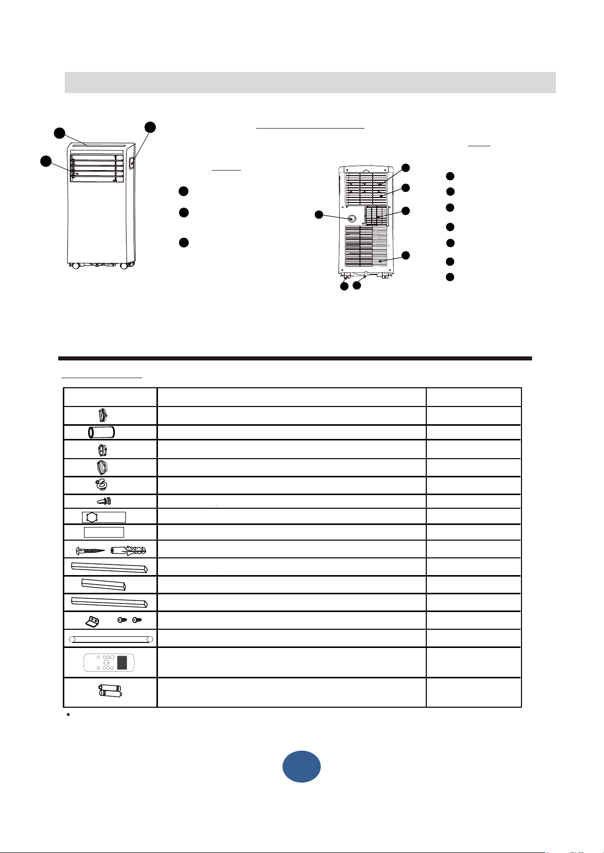
IDENTIFICATION OF PARTS
1
3
Accessories
PARTS : PARTS NAME :
2
NAMES OF PARTS
Front
Operation Panel
1
Carrying Handle
2
(both sides)
Cold air outlet
3
Fig.1
Unit Adaptor
Exhaust Hose(Length: 1.4m, diameter: 130mm)
Window Slider Adaptor
Wall Exhaust Adaptor A (only for wall installation)
Wall Exhaust Adaptor B(with cap)(only for wall installation)
Bolt
Window Slider A
Window Slider B
Screw A ST4.5x45 and wall plug(only for wall installation)
Foam Seal A (Adhesive)
Foam Seal B (Adhesive)
8
10
6
4
7
5
9
Fig.2
Rear
Air Filter
4
Air Outlet
5
6
Wheel
Air intake (with filter)
7
8
Drain Outlet
Air intake
9
Bottom tray drain outlet
10
QUANTITY :
1 pc
1 pc
1 pc
1 pc
1 pc
1 pc
1 pc
1 pc
4 set
2 pc
2 pc
Foam Seal C (Non-adhesive)
Bracket x 1 and screw (ST3.9x13) x 2
Drain Hose(Length: 0.6m, diameter: 16.5mm)
ON/
SLEEP
M
FA
O
O
D
N
E
F
F
T
E
M
P
SH
T
T
C
O
O
IM
I
L
M
O
U
ED
N
F
ER
ER
RT
T
F
Remote control
Battery(LR03)
1 pc
1 set
1 pc
1 pc
2 pc
Check all the accessories are included in the package and please refer to the installation instructions for
their usage.
4
5
Page 6
INSTALLATION INSTRUCTIONS
INSTALLATION INSTRUCTIONS
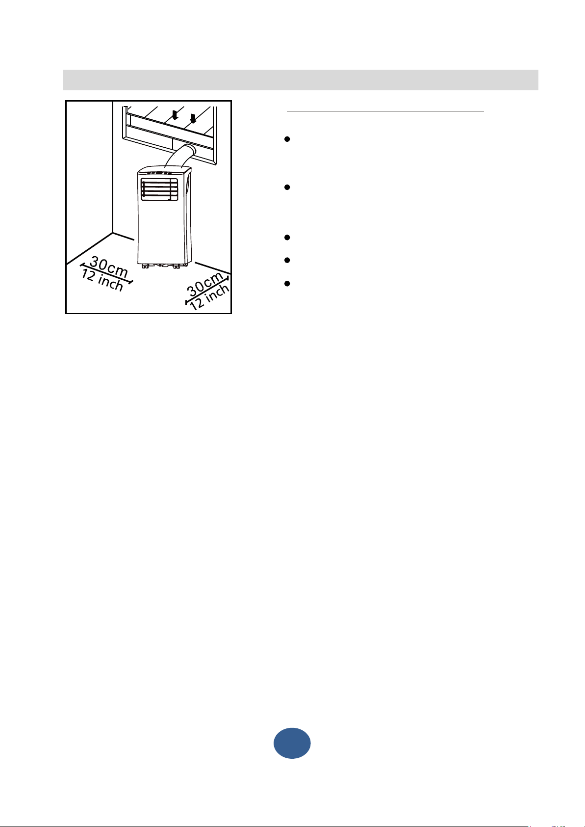
Location
The air conditioner should be placed on a firm
foundation to minimize noise and virbration. For
safe and secure positioning, place the unit on a
smooth, level floor strong enough to support the unit.
The unit has casters to aid placement, but it should
only be rolled on smooth, flat surfaces. Use caution
when rolling on carpet surfaces. Do not attempt to
roll the unit over objects.
The unit must be placed within reach of a properly
rated grounded socket.
Never place any obstacles around the air inlet or
outlet of the unit.
Allow at least 30cm of space from the wall for
efficient air-conditioning.
Fig. 3
5
Page 7

INSTALLATION INSTRUCTIONS
For hung/sliding window
Exhaust hose
Unit adaptor
For wall installation
Exhaust hose
Unit adaptor
Exhaust hose assembly
Window slider adaptor
FAN,DEHUMIDIIFY mode
Exhaust hose assembly
Wall exhaust adaptor A
Fig. 4
Fig.5
Exhaust hose installation:
The exhaust hose and adaptor must be installed or removed
in accordance with the usage mode.
COOL, AUTO mode
1. Connect the exhaust hose into the window slider adaptor (into
wall window slider adaptor for wall installation) and unit adaptor,
clamp automatically by elastic buckles of the adaptors (See Fig.4).
2. Push the Exhaust hose into the air outlet opening along the
the arrow direction(See Fig. 5).
Preparing the Adjustable Window Slider
1. Depending on the size of your window, adjust the size of the
window slider.
2. If the length of the window requires two window sliders, use
the bolt to fasten the window sliders once they are adjusted
to the proper length.
Installation
Note: Once the Exhaust Hose assembly and Adjustable Window
Slider are prepared, choose from one of the following three
installation methods.
Install
Remove
Type 1: Hung Window Installation(optional)
Foam seal B
(Adhesive type-shorter)
Window slider B
Window slider A
(if required)
Foam seal A
(Adhesive type)
Cut the adhesive foam seal A
and B strips to the proper
lengths, and attach them to
Insert the window slider
assembly into the window
opening.
the window sash and frame
as shown.
Foam seal C
(Non-adhesive type)
Security Bracket
2 Screws
Cut the non-adhesive foam
seal C strip to match the width
If desired, install the security
bracket with 2 screws as shown.
of the window. Insert the seal
between the glass and the
window frame to prevent air
and insects from getting into
the room.
6
Page 8

INSTALLATION INSTRUCTIONS
Expansion anchor
Type 3: Wall Installation(optional)
-Cut a 125mm (4.9inch) diameter hole into the wall for the Wall Exhaust Adaptor B.
-Secure the Wall Exhaust Adaptor B to the wall using the four Anchors
and Screws provided in the kit.
-Connect the Exhaust Hose Assembly(with Wall Exhaust Adaptor A) to the
Wall Exhaust Adaptor B.
Insert the window slider adaptor
into the hole of the window slider.
Type 2: Sliding Window Installation(optional)
Foam seal B
(Adhesive type-shorter)
Window slider B
Foam seal A
(Adhesive type)
Cut the adhesive foam seal A
and B strips to the proper
lengths, and attach them to
Insert the window slider
assembly into the window
opening.
(if required)
Window slider A
the window sash and frame
as shown.
Foam seal C
(Non-adhesive type)
Security
Bracket
Wall Exhaust
Adaptor B
Adaptor cap
Note: To ensure proper function, DO NOT overextend or bend
the hose. Make sure that there is no obstacle around the air
outlet of the exhaust hose (in the range of 500mm) in order to
the exhaust system works properly. All the illustrations in this
manual are for explanation purpose only. Your air conditioner
may be slightly different. The actual shape shall prevail.
position
Note: Cover the hole using the
adaptor cap when not in use.
max 120cm or 47 inch
min 30cm or 12 inch
Cut the non-adhesive foam
seal C strip to match the
If desired, install the security
bracket with 2 screws as shown.
window height. Insert the foam
seal between the glass and the
window frame to prevent air
and insects from getting into
the room.
Insert the window slider adaptor
into the hole of the window slider.
2 Screws
7
Page 9

INSTALLATION INSTRUCTIONS
Water drainage:
- During dehumidifying modes, remove the drain
Remove the
drain plug
plug from the back of the unit, install the drain
connector(5/8 universal female mender) with
3 4 hose(not included). Place the open end
of the hose directly over the drain area .
Please refer to Fig.6 & 7.
Fig.6
Continuous
drain hose
Fig. 7
-
Under dehumidifying mode, when the water level
of the bottom tray reaches a predetermined level,
the unit beeps 8 times, the digital display area
shows "P1". At this time the air conditioner will
stop immediately. However, the fan motor will
continue to operate (this is normal).
Carefully move the unit to a drain location,
remove the bottom drain plug and let the
water drain away (Fig.8). Re-install the bottom
drain plug and Restart the machine until the P1
symbol disappears. If the error repeats, call for
service.
NOTE: Be sure to reinstall the bottom drain plug
before using the unit.
Bottom drain
plug
Fig.8
8
Page 10

OPERATION
Control Panel
Fig. 9
MODE button
Selects the appropriate operating
mode. Each time you press the button,
a mode is selected in a sequence that
goes from COOL, FAN and DRY .The
mode indicator light illuminates under
the different mode setting.
NOTE: On above modes, the unit
operates the auto fan speed
automatically. You can set fan speed
only by the remote control on
COOL and FAN modes.
Up (+) and Down (-) buttons
Used to adjust (increasing/decreasing)
temperature settings in 1°C/2°F(or 1°F)
increments in a range of 17°C/62°F to
30°C/88°F (or 86°F).
NOTE: The control is capable of
displaying temperature in degrees
Fahrenheit or degrees Celsius. To
convert from one to the other, press
and hold the Up and Down buttons
at the same time for 3 seconds.
Power button
Turn the unit on/off.
LED display
Shows the set temperature while on cool
Power
indicator light
Timer mode indicator
light (set only by
remote control)
mode. While on DRY and FAN modes, it
shows the room temperature.
Shows Error codes:
E1-Room temperature sensor error.
E2-Evaporator temperature sensor error.
E4-Display panel communication error.
EC-Refrigerant leakage detection
malfunction(on some models).
Shows protection code:
P1-Bottom tray is full--Connect the drain
hose and drain the collected water away.
If protection repeats,call for service.
Note: When one of the above malfunctions
occurs, turn off the unit, and check for any
obstructions. Restart the unit, if the
malfunction is still present, turn off the unit
and unplug the power cord. Contact the
manufacturer or its service agents or a
similar qualified person for service.
9
Page 11

OPERATION
Power
indicator light
Timer mode indicator
light (set only by
remote control)
Operating Instruction
COOL operation
Continue to
- press the "MODE" button until the
"COOL"
- press the ADJUST buttons " " or "
temperature can be set within a range of
-
Dehumidifying operation
- Press the "MODE" button until the
"DRY" indicator light comes on.
- Under this mode, you cannot select a
fan speed or adjust the temperature.
- Keep windows and doors closed for
the best dehumidifying effect.
- Do not put the hose to window.
FAN operation
-
- To change the fan speed, please use the remote
control.
- Do not put the hose to window.
Remark
Auto-Restart
If the unit shut down unexpectedly due t o th e
power cut,it will restart with t he pr eviou s
function setting automatically when the power
resumes.
indicator light comes on.
Continue to
select your desired room temperature. The
" to
To change the fan speed, please use the remote
control.
E" butt
Press the "MODE" button until the"FAN"indicator
light comes on.
"
O O
17 C-30 C
Important for compressor protection device
After the unit has stopped, it cannot operation in the first 3 minutes. This is to pro tec t t he unit .
Operation will automatically s tar t after 3 min utes.
Air flow direction adjustment
Adjust the air flow direct ion man ual ly
The louver can be set to the de sired position manually.
Do not place any heavy obje cts or o the r lo ads on the louver, doing so will cause damage to
the unit.
Keep the louver fully open ed d uri ng o per ati on.
10
Page 12

REMOTE CONTROL
Handling the remote control
8m
ON/O
FF
MO
DE
SH
O
CU
R
T
FA
T
N
T
E
MP
T
I
M
E
ON
R
TIMER
S
LEE
OF
P
F
LED
Location of the remote control
Use the remote control within a distance of 8 meters from the
appliance, pointing it towards the receiver. Reception is confirm by a beep.
CAUTIONS
The air conditioner will not operate if curtains, doors or other materials block the signals
from the remote control to the indoor unit.
Prevent any liquid from falling into the remote control. Do not expose the remote
control to direct sunlight or heat.
If the infrared signal receiver on the indoor unit is exposed to direct sunlight, the air
conditioner may not function properly. Use curtains to prevent the sunlight from falling on
the receiver.
If other electrical appliances react to the remote control. either move these appliances
or consult your local dealer.
ed
Replacing batteries
The remote control is power by two dry batteries
(R03/LR03X2) housed in the rear part and protected
by a cover.
(1) Remove the cover by pressing and sliding off.
(2) Remove the old batteries and insert the new
batteries, placing the(
(3) Replace the cover by sliding it back into position.
CAUTIONS
Do not mix old and new batteries or batteries of a different type.
Do not leave the batteries in the remote control if it is not going to be used for more than 2 months.
Dispose of the old batteries in the special containers to be found in the sales outlets.
8
11
+) and (-) ends correctly.
Page 13

REMOTE CONTROL
Function buttons
1
2
3
4
ON/OFF Button
1
ON/OFF
MODE
FAN
SLEEP
TEMP
SHORT
CUT
TIMER
ON
TIMER
OFF
LED
Operation starts when this button is pressed and
stops when the button is pressed again.
MODE Button
2
It is for you to select different operation mode.
FAN SPEED Button
3
Used to select the fan speed in four steps:
Auto Low High
SLEEP Button
4
Select this function during the sleeping time. It can
maintain the most comfortable temperature and save
energy. This function is available on COOL, or AUTO
mode only .
This feature can be activated from the remote control
ONLY. To activate SLEEP feature, the set
temperature will increase by 1 °C/2°F(or 1 °F) in
30 minutes. The set temperature will then increase by
another 1 °C/2°F(or 1 °F) after an additional 30 minutes.
This new temperature will be maintained for 7 hours
before it returns to the originally selected temperature.
This ends the Sleep mode and the unit will continue to
operate as originally programmed.
NOTE: This feature is unavailabe under FAN or
Dehumidifying mode.
5
6
7
8
9
SHORT CUT Button
5
Sets and activates your favorite pre-settings.
Used to restore the current settings or resume
previous settings.
Push this button when remote controller is on, the
system will automatically revert back to the previous
settings including operating mode, setting
temperature, fan speed level and sleep feature (if
activated).
If pushing more than 2 seconds, the system will
automatically restore the current operation settings
including operating mode, setting temperature, fan
speed level and sleep feature(if activated).
6
TEMP UP/DOWN BUTTON
Push UP button to increase the indoor
temperature
setting in 1℃ increments to 30℃.
Push DOWN button to decrease the indoor
temperature
7
TIMER OFF Button
setting in 1℃ decrements to 17℃.
Press this button to activate the Auto-off time
setting. Each press will increase the time setting in
30 minutes increments, up to 10 hours, then at 1
hour increments up to 24 hours. To cancel the
Auto-off time setting, just press the button until the
time setting is 0.0.
TIMER ON Button
8
Press this button to activate the Auto-on time
setting. Each press will increase the time setting in
30 minutes increments, up to 10 hours, then at 1
hour increments up to 24 hours. To cancel the
Auto-on time setting, just press the button until the
time setting is 0.0.
LED Button
9
Turns unit's LED display on and off. If you are
sensitive to light when you go to sleep, you can
press the LED button to turn off the LED display on
the unit. Press the button again to turn it back on.
NOTE:
While the unit is running under SLEEP mode,
it would be cancelled if ON/OFF, FAN SPEED,
SLEEP or MODE button is pressed.
12
8
Page 14

REMOTE CONTROL
Transmission Indicator
Lights up when remote sends
signal to unit
ON/OFF display
Appears when the unit is turned on,
MODE display
Displays the current
mode, including:
AUTO
COOL
DRY
FAN
and disappears when it is turned off
TIMER ON display
Displays when TIMER
ON is set
TIMER OFF display
Displays when TIMER
OFF is set
Battery display
Low battery
detection
SLEEP display
Displays when
SLEEP function
is activated
FAN SPEED display
Displays selected FAN SPEED:
HIGH,
or LOW
This display is blank when
set to AUTO speed.
Temperature/Timer display
Displays the set temperature by default, or timer setting
when using TIMER ON/OFF functions
Temperature range: 17-30 C(62 F-86 F)
Timer setting range: 0-24 hours
This display is blank when operating in FAN mode.
o O O
13
Page 15

CARE AND MAINTENANCE
CARE AND MAINTENANCE
Air filter
(take out)
IMPORTANT:
1) Be sure to unplug the unit before cleaning or servicing.
2) Do not use gasoline, thinner or other chemicals to clean
the unit.
3) Do not wash the unit directly under a tap or using a hose.
It may cause electrical danger.
4) If the power cord is damaged, it should be repaired by
manufacture or its agency.
1. Air filter
- Clean the air filter at least once every two weeks.
- Removal
This unit has an upper filter. Take it out along the arrow
direction, then take the filter down.
- Cleaning
Wash the air filter by immersing it gently in warm water
(about 40 C) with a neutral detergent. Rinse the filter
and dry it in a shady place. Do not put it under the direct
sunlight.
- Mounting
Install the upper filter after cleaning.
O
2. Unit enclosure
- Use a lint-free cloth soaked with neutral detergent to clean
the unit enclosure. Finished by a dry clean cloth.
3. Unit idle for a long time
- Remove the rubber plug at the back of the unit and attach
a hose to drain outlet
. Place the open end of the hose
directly over the drain area in your basement floor
- Remove the plug from the bottom drain outlet, all the water
in the bottom tray would drain out.
- Keep the appliance running on FAN mode for half a day in
a warm room to dry the appliance inside and prevent mold
forming.
- Stop the appliance and unplug it, wrapped the cord and
bundle it with the tape. Remove the batteries from
the remote control.
- Clean the air filter and reinstall it.
14
Page 16

TROUBLESHOOTING TIPS
TROUBLE SHOOTING
TROUBLES
1. Unit does not
Start when
Pressing on/off
Button
2. Not cool enough
3. Noisy or vibration
4. Gurgling sound
5. LED displays E1 code
6. LED displays E2 code
POSSIBLE CAUSES
- P1 appears in the display window
- Room temperature is lower than
the set temperature.(Cooling mode)
- The windows or doors in the room
are not closed.
- T
here are heat sources inside the
room.
- The unit is low on refrigerant.
- Exhaust air duct is not connected or
blocked.
- Temperature setting is too high.
-
Air filter is blocked by dust.
- The air filter is blocked with dust
- The ground is not level or not flat
enough.
- T
he sound comes from the flowing
of the refrigerant inside the
air-conditioner.
Room temperature sensor error
-
Evaporator temperature sensor error
-
SUGGEST REMEDIES
Drain the water in the bottom tray.
Reset the temperature.
Make sure all the windows and
doors are closed.
Rem
ove the heat sources if possible.
Call a service technician to inspect the
unit and top off refrigerant
Connect the duct and make
sure it can function properly
Decrease the set temperature.
Clea
n the air filter.
Clean the air filter.
Place the unit on a flat, level
ground if possible.
It is normal.
Unplug the unit and plug in.
If error is still happened, please check
with the qualified person / or return it to
store.
Unplug the unit and plug in.
If error is still happened, please check
with the qualified person / or return it to
store.
.
7. LED displays E4 code
8. LED displays P1 code
Display panel communication error
-
Bottom tray is full
-
15
Unplug the unit and plug in.
If error is still happened, please check
with the qualified person / or return it to
store.
Connect the drain hose and drain the
collected water away.
If error is still happened, please check
with the qualified person / or return it to
store.
Page 17

PRODUCT SPECIFICATIONPRODUCT SPECIFICATION
The figures below are for reference only and are based on practical operation.
Performance may vary slightly depending on environmental conditions.
Description of product Local air conditioner
Model
MPPHA-05CRN1-QB6
Voltage/Frequency 220-240V /50Hz
5000BTU/H
~
Cooling capacity
1.4 kW
Dehumidifying capacity
1.4L/H
Refrigerant R-410A/200g
Timer 24 hours
Air flow volume 275 m³/hour
Dimensions
32.9x61.5x31.8
(W) X (H) X (D)
Weight
R
oom size Up to 10 ㎡
19.5kg
Contains fluorinated greenhouse gases covered by the Kyoto
Protocol.
GWP:2088; 0.42 tonnes CO2 equivalent.
Hermetically sealed.
16
Page 18

13Amp
DISPOSAL: Do not dispose this product as unsorted municipal waste. Collection
of such waste separately for special treatment is necessary.
It is prohibited to dispose of this appliance in domestic household waste.
For disposal, there are several possibilities:
A) The municipality has established collection systems, where electronic waste
can be disposed of at least free of charge to the user.
B) When buying a new product, the retailer will take back the old product at least
free of charge.
C) The manufacture will take back the old appliance for disposal at least free of
charge to the user.
D) As old products contain valuable resources, they can be sold to scrap metal
dealers.
Wild disposal of waste in forests and landscapes endangers your health when
hazardous substances leak into the ground-water and find their way into the food
chain.
17
Page 19

TECHNICAL INFORMATION (ERP)
1.4
0.6
2.6
1.0
0.5
0.6
65
2088
Customer helpline 0345 640 0800
Installs, services, maintains, repairs, checks f or leaks or decommissions equipment and
product recycling should be carried out by natural persons that hold relevant certificates.
The fluorinated greenhouse gases are contained in hermetically sealed equipment.
18
Page 20

19
 Loading...