

Page 1

The Challenge Machinery Company
6125 Norton Center Drive
Norton Shores, MI 49441-6081 USA
ChallengeMachinery.com
The Challenge Machinery Company provides owner's manuals on its
products solely as a courtesy to its customers. See the information below
before using this manual.
These manuals are for reference only. These manuals include products which are noncurrent,
unsupported or no longer produced by The Challenge Machinery Company, and are provided solely as
an accommodation to our customers. By providing these manuals, The Challenge Machinery Company
makes no representation or warranty as to the products, their current condition, or their suitability or fitness
for use in any particular application, which are the sole and independent responsibility of the product
owner and user.
Older products may not comply with current safety procedures, guidelines or regulations, and it
is the product owner's and user's responsibility to evaluate the suitability and fitness of the
products in their current use and application. The Challenge Machinery Company makes no
representation, warranty or recommendation regarding any modifications which may be required
on non-current or unsupported products. The Challenge Machinery Company assumes no liability
for any modification or alteration to any Challenge product, and any such modification or
alteration to any Challenge product is not authorized by The Challenge Machinery Company. The
availability of these manuals is solely for the purpose of providing reference information for the products.
This manual may not be complete in all aspects of product maintenance and repair. All products should
be used only by qualified and properly trained personnel, following proper safety procedures. All
products should be regularly inspected and maintained, and their condition, application and use should
be periodically evaluated by qualified personnel. Only qualified and properly trained technicians should
perform maintenance, repair and replacement procedures. Attempting these procedures without proper
training may cause machine damage or operator injury!
Products may be unsupported by The Challenge Machinery Company due to age or the unavailability of
parts from their original manufacturer. No parts or product support will be available to repair or maintain
unsupported products. Older products may not be UL listed (if the product does not have a UL label it is
not a listed product), and may not comply with applicable installation or other regulations or requirements
if relocated to a new facility. Many municipalities require a product to be UL listed before an electrician
will connect power to them. Often the cost of updating an older product to comply with current safety
regulations is greater than the value of the product.
HANDY-DRILL
Instruction and Parts Manual
055188 through 159999,
HDDR-A-150000 and up
Sold and Serviced by
F.101-A
Serial Numbers:
November 2015
Page 2
1.0 Introduction
CHALLENGE MODEL Handy-Drill
SERIAL NUMBER
ATTN
COMPANY
ADDRESS
CITY
STATE/PROVINCE
ZIP
PHONE
DATE INSTALLED
DEALER NAME & CITY
1.0 Introduction
THIS MANUAL is designed to help you get the most from your Challenge equipment. Keep this
manual in a safe, convenient place for quick reference by operators and service personnel.
SAFETY ALERT! This symbol means CAUTION: Personal safety
instructions! Pay special attention to the instructions in bold type. Personal injury may result if the
precautions are not read and followed.
READ THIS MANUAL BEFORE OPERATING! Follow precautions and instructions. If after reading
the manual, questions remain, please contact your Authorized Challenge Dealer.
Take a few minutes right now to RECORD YOUR MACHINE SERIAL NUMBER in the space
provided on the front cover of this manual. Also be sure to fill out the warranty card accompanying
your machine and return it DIRECTLY TO CHALLENGE.
If you bought a used machine, it is important to have the following information on record at Challenge.
Copy this page, fill in the information and send it care of The Challenge Service Department, 6125
Norton Center Drive, Norton Shores MI. 49441.
* WARRANTY INFORMATION *
It is very important that you read and understand the conditions outlined in the Warranty Information
Sheet attached to the outside of the shipping container of your machine.
The Warranty Information Sheet must be filled out completely and returned to THE CHALLENGE
MACHINERY COMPANY in order for the warranty to be issued for this machine.
The Challenge Machinery Company 6125 Norton Center Drive Norton Shores MI. 49441
Copyright© 2015 by The Challenge Machinery Company. All rights reserved. Printed in the U.S.A
Challenge® is a registered trademark of
2
Page 3

1.0 Introduction
TABLE OF CONTENTS
1.0 Introduction .......................................................................................................................................2
2.0 Safety ................................................................................................................................................4
2.1 Precautions ...................................................................................................................................4
2.2 Power Lockout Procedure ............................................................................................................4
2.3 Warning Label Definitions .............................................................................................................5
3.0 Packing List .......................................................................................................................................7
4.0 Specifications ....................................................................................................................................8
Minimum Distance Btw. Holes ........................................................................................................8
5.0 Footprint ............................................................................................................................................9
6.0 Installation & Setup ........................................................................................................................ 10
6.1 Inspecting Shipment .................................................................................................................. 10
6.2 Uncrating ................................................................................................................................... 10
6.3 Cleaning ..................................................................................................................................... 10
6.4 Assemble Loose Items .............................................................................................................. 10
6.5 Power Hook-Up ......................................................................................................................... 10
7.0 Operation ....................................................................................................................................... 11
7.1 Set Hole Spacing ....................................................................................................................... 11
7.2 Set Drilling Depth ....................................................................................................................... 11
7.3 Drilling ........................................................................................................................................ 12
7.4 Rotate the Drilling Block ............................................................................................................ 12
7.5 Empty the Paper Chips .............................................................................................................. 12
8.0 Drilling Tips .................................................................................................................................... 13
Maintenance Section ............................................................................................................................ 15
9.0 Routine Maintenance ..................................................................................................................... 16
9.1.1 Weekly ................................................................................................................................ 16
9.1.2 Monthly ............................................................................................................................... 16
10.0 Troubleshooting ........................................................................................................................... 17
11.0 Parts Lists .................................................................................................................................... 18
11.1 Main Assembly – Arch ............................................................................................................. 18
11.2 Main Assembly – Head ............................................................................................................ 20
11.3 Main Assembly – Head ............................................................................................................ 22
11.4 Main Assembly – Covers ......................................................................................................... 24
11.5 Backgauge Assembly .............................................................................................................. 26
11.6 Interconnection Diagram ......................................................................................................... 28
3
Page 4
2.0 Safety
2.0 Safety
2.1 Precautions
This machine is designed for one-person operation. Never operate the machine with more than
one person.
Always wear safety glasses while operating this machine.
Safe use of this machine is the responsibility of the operator. Use good judgment and common
sense when working with and around this machine.
Read and understand all instructions thoroughly before using the machine. If questions remain,
contact the dealer from which you purchased this machine. Failure to understand the operating
instructions may result in personal injury.
Only trained and authorized people should operate this machine.
DO NOT ALTER SAFETY GUARDS OR DEVICES. They are for your protection. Severe
personal injury may result.
Disconnect power before cleaning or performing maintenance. See Section 2.2 Power Lockout
Procedure.
Observe all caution labels on this machine.
Be sure the drill is plugged into a properly grounded outlet.
Be sure there is sufficient power to operate the drill properly.
Observe all caution plates mounted on the drill.
Keep foreign objects off table and away from the spindle and bit.
BE EXTREMELY CAREFUL when handling and changing drill bits. Drill bits are sharp. Severe
lacerations could result from careless handling procedures.
If the drill sounds or operates unusually, have it checked by a qualified service person.
CUT/CRUSH HAZARD, keep hand and fingers from under the clamp and spindle while drilling
paper. DO NOT REACH UNDER THE DRILL AREA WHILE OPERATING!
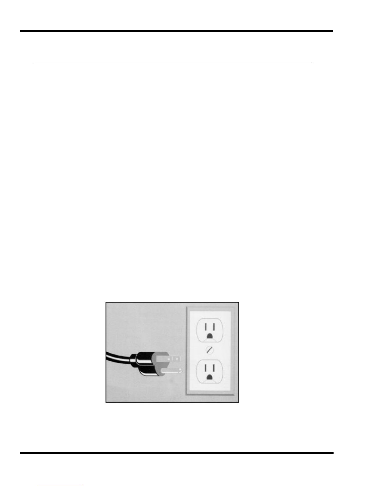
2.2 Power Lockout Procedure
For maximum safety while making adjustments or repairs to your machine, be sure to disconnect
power to the machine. Disconnect the power plug from its socket
Figure 1 - Main Power Disconnect
4
Page 5
2.0 Safety
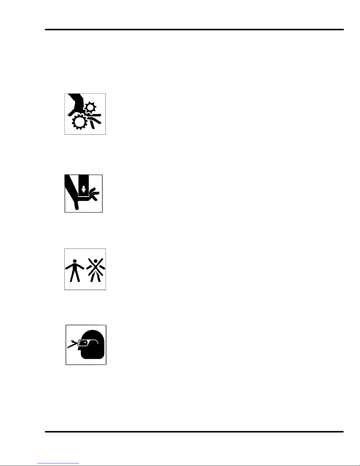
2.3 Warning Label Definitions
The following warning labels are found at various locations on your machine. Read and understand
the meaning of each symbol. If a label is lost from the machine, it should be replaced.
HAZARDOUS AREA
Disconnect power before cleaning, servicing, or making adjustments not requiring
power. Do not alter safety guards or devices; they are for your protection. Replace
all guards. Do not operate with any guards removed.
CUT/CRUSH HAZARD
Keep hands from underneath the knife and clamp.
SINGLE OPERATOR
Do not operate with more than one person.
EYE PROTECTION
Always wear safety glasses while operating drill.
5
Page 6

2.0 Safety
!OJO!
This Este simbolo de alerta de seguridad significa ¡ OJO ! INSTRUCCIONES DE SEGURIDADPERSONAL. Lea las instrucciones porque se refieren a su
seguridad personal. Fall de obedecer las instrucciones que siguen podria resultar en lesiones
corporales.
Esta maquina, junto con sus mecanismos de seguridad, esta disenada para ser manejada por
UNA SOLA PERSONA a la vez. Jamas debe ser manejada por mas de una persona al mismo
tiempo.
La seguridad es la responsabilidad del operario que usa esta maquina.
LEA DETENIDAMENTE el manual de instrucciones y las PRECAUCIONES DE SEGURIDAD
antes de poner a funcionar la cortadora. Pidale a su supervisor una copia.
El manejo de la guillotina debe estar exclusivamente a cargo de personal entrenado y autorizado
para ello.
NO MODIFIQUE LOS MECANISMOS DE SEGURIDAD, estan ahi para su proteccion no deben
ni modificarse ni quitarse.
DESCONECTE LA CORRIENTE ELECTRICA antes de proceder a hacerle servicio de limpieza,
engrasar, o de hacer adjustes que no requieren corriente. Trabe el interruptor en la posicion
OFF (apagado); vea “Procedimiento para cortar la corriente electrica” al pie de esta pagina.
Eche llave a la guillotina y quite la llave cuando la maquina no esta en operacion; vea “Corriente
electrica”.
Asegurese de que la guillotina este debidamente a tierra. Vea “Conexion de la fuerza electrica”.
Verifique el voltaje y asegurese de que este sea suficiente para el debido funcionamiento de la
guillotina.
Preste atencion a todas las placas con advertencias instaladas en esta guillotina.
No permita que objetos estranos esten en la mesa o cerca de la cuchilla cortadora.
TENGA SUMO CUIDADO al tocar y cambiar la cuchilla. Heridas severas y hasta
desmembramiento pueden resultar del manejo sin cuidado o negligente.
El suelo alrededor de la guillotina debe mantenerse despejado y libre de recortes, desperdicios,
aceite y grasa.
Al haber la necesidad de reemplazar partes hidraulicas, afloje todas las conexiones poco a poco
para dejar escapar la presion. Jamas debe aflojarse conexiones mientras la maquina este
andando.
Si la guillotina empezara a sonar o trabajar diferentemente a lo acostumbrado, desconectela y
consulte la seccion “Troubleshooting” (Reparador) de este manual. Si no es posible corregir el
problema, llame a su servicio autorizado para que le examinen la maquina.
PELIGRO DE MACHUQUE - Mantenga manos y dedos fuera de la agarradera mientras sujeta el
papel. Use el calibrador trasero y su rueda de mano para empujar el papel cortado. NO PONGA
SUS MANOS BAJOLA CUCHILLA O AREA DE LA AGARRADERA.
NO OPERE SIN LAS GUARDAS PROTECTORAS!
¡ OJO ! PRECAUCION - Como proceder para desconectar
la corriente electrica.
Para maxima seguridad durante ajustes y reparaciones de su maquina, verifique bien que el interruptor principal
de control de corriente al cual la maquina esta conectada, este desconectado. El interruptor deba ser puesto en
la posicion “OFF” (desconectado) y se debe poner un candado en la anilla. La llave del candado debe ser
guardada por la persona que estara efectuando los trabajos de servicio o de reparacion en la guillotina.
Desconecte la corriente electrica antes de proceder a hacer cualquier ajuste o reparacion o de efectuar el
engrase en cualquier maquina.
6
Page 7
3.0 Packing List
Part No.
Description
Qty.
Handy-Drill
Single Spindle Tabletop Paper Drilling Machine
1
64026
Backgauge Assembly
1
4681
Drill Block
1
F.101-O
Operator’s Manual
1
4688
Lubrication Stick (for lubricating drill bits)
1
4687
Drill Drift (for removing drill bits)
1
W-190
1/8 Hex Wrench
1
W-170
9/16 X 1/2 Wrench
1
W-130
3/16 Hex Wrench
1
W-192
3/32 Hex Wrench- Short
1
Part No.
Description
Qty.
A-4682
Wood Drill Blocks (12 per container)
1
57100
Handy-Sharp Drill Bit Sharpener
1
A-4950-1
Handy Chip Remover
1
Replacement Bits
See your Dealer for Original Challenge Bits
3.0 Packing List
Optional Items
7
Page 8

4.0 Specifications
Description
Inch Units
Metric Units
Drill Head Operation, Hand Lever
Drill Diameters
13 sizes from 1/8” to ½”
3-13mm
Lift Capacity
2-1/2” for drills ¼” or larger
64mm
Minimum Distance Btw. Holes
3/8” center to center
10mm
Maximum Distance Drill to Side Guide
9-7/8”
25.5cm
Maximum Margin Hole Center to Sheet
Edge
2-1/2”
6.4cm
Side Guide Trip
Manual
Dimensions
Net Weight
70 lbs
32 kg
Shipping Weight
90 lbs
41 kg
Table Space
18” x 19”
46 x 48cm
Height Overall
22-3/8”
56.8cm
Electrical
115 Volts, 2.7 Amps, 60Hz, 1 phase, AC.
Use 3 Amp Slo-Blo fuse.
Challenge reserves the right to make changes to any product or specification without notice and
without incurring responsibility to existing units.
4.0 Specifications
8
Page 9
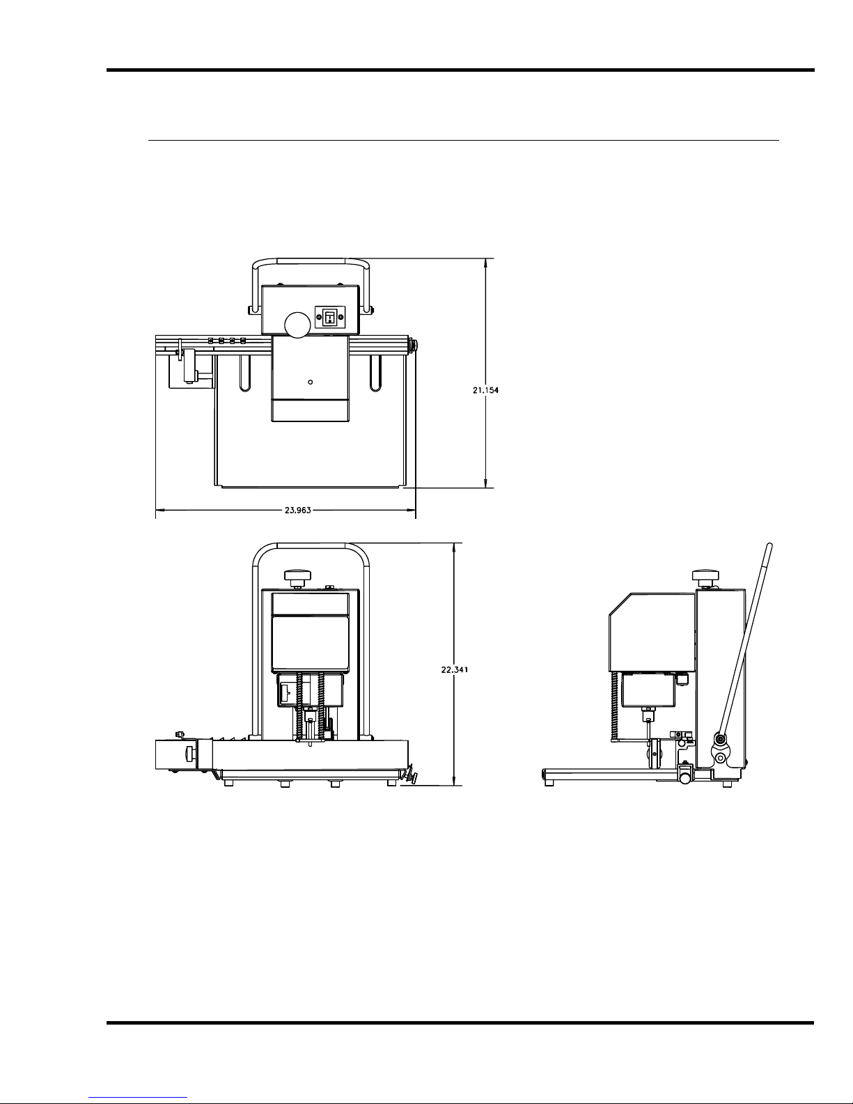
5.0 Footprint
5.0 Footprint
9
Page 10

6.0 Installation & Setup
6.0 Installation & Setup
6.1 Inspecting Shipment
This machine has been carefully packed to prevent damage during shipment. However, claims for
damage or loss are the responsibility of the recipient. Inspect all shipments as soon as they are
received. If there is any noticeable damage, note it on the freight bill. Visual and/or hidden damage
must be reported to the claims department of the carrier within 15 days. Contact your dealer if you
need any assistance. Check the contents of the box against the packing list on page 7. Make sure
there are no missing items.
6.2 Uncrating
The Handy-Drill weighs approximately 70 lbs (32 kg). DO NOT risk personal injury or damage by
attempting to move machinery with makeshift equipment or inadequate help. This machine is
shipped enclosed in a corrugated carton. Open the top of the carton and carefully lift machine out
and set on to work surface.
6.3 Cleaning
After unpacking, wipe down all machine panels and surfaces with a clean cloth as necessary.
6.4 Assemble Loose Items
1. Insert the wood drilling block into the hole in the tabletop.
2. Insert the hollow drill bit into the spindle. Push the bit firmly into the spindle. The drill bit is sharp;
do not push on the end of the drill bit. Injury may result.
3. The machine was shipped with the drilling depth set above the drilling block. Adjust the drilling
depth according to Section 7.2 Set Drilling Depth.
6.5 Power Hook-Up
SHOCK HAZARD! Possible shock could cause personal injury or death.
Connect plug to any standard 120 Volt outlet.
Figure 2 – Main Power Disconnect
10
Page 11

7.0 Operation
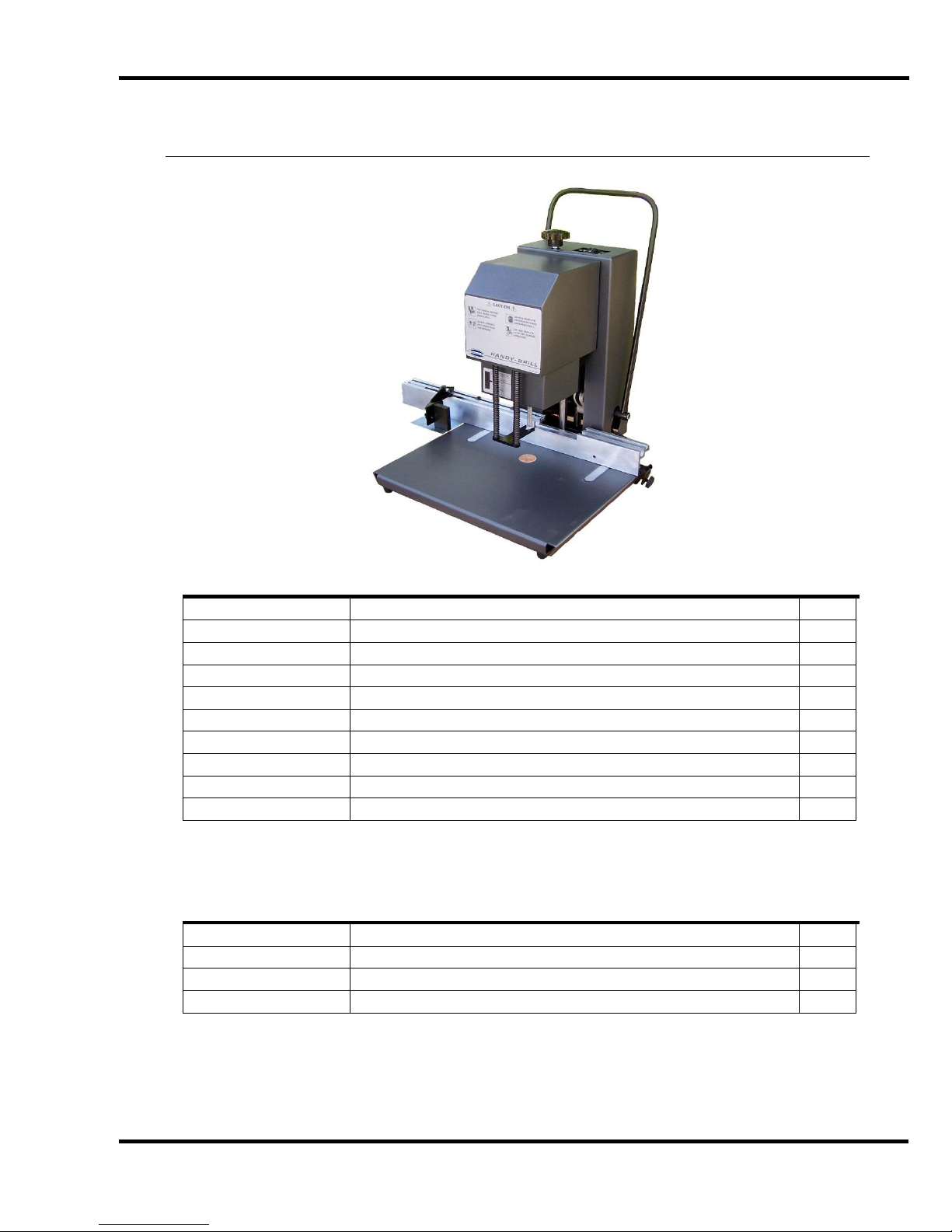
Power Switch
Chip Collector
Handle
Backgauge
Depth Adjustment Knob
Drill Bit
Pressure Foot
Side Stop Lever
7.0 Operation
IMPORTANT: DO NOT ATTEMPT TO OPERATE THE DRILL UNTIL
YOU HAVE THOROUGHLY READ AND UNDERSTAND ALL OF THE FOLLOWING
INSTRUCTIONS. CALL YOUR AUTHORIZED CHALLENGE DEALER IF YOU STILL HAVE ANY
QUESTIONS.
Figure – Machine Controls
7.1 Set Hole Spacing
The Handy-Drill backgauge has been set to drill standard three-ring holes, plus one extra stop for
four-hole drilling. The stops are held in place with setscrews that run through the top of the stop. Use
the 3/32” hex wrench provided in the toolkit in order to loosen the setscrews. Slide the stop to the
required dimension as read from the scale on top of the backgauge. Tighten the setscrew until the
stop is held firmly in place.
7.2 Set Drilling Depth
Turning the adjustment knob on top of the machine sets the depth to which the machine will drill. To
drill deeper, turn the knob counter-clockwise. To drill shallower, turn the knob clockwise. The drill
depth should be set such that the bottom sheet is cut through without going excessively cutting into
the drilling block. Use scrap pieces of paper to set the drill depth.
Important: Always check and adjust the drill depth whenever changing drill bits. The adjustment
range will accommodate both 2” and 2-1/2” drill bits.
11
Page 12

7.0 Operation
7.3 Drilling
After the machine has been properly installed and adjusted, it is ready for drilling. Set the side stop to
the first position and jog stock against the backgauge and side guide. Switch on the machine by
pressing the rocker switch to “I”. Pull the handle to start the motor and drill. Pull the handle until the
stock is drilled through. Raise the handle to its starting position. The motor will automatically shut off.
Lift the side stop lever and slide the side stop to the next position. Continue drilling as described
above.
7.4 Rotate the Drilling Block
As the drilling block wears, the bottom few sheets may not be cut through. Rotating the drilling block
to a new position will correct this. The drilling depth may also need adjustment. After the drilling
block has been worn in all the available area on one surface, it may be turned over to use the other
surface.
7.5 Empty the Paper Chips
The paper chip collectors should be emptied periodically. Check the level of paper chips in the
collectors by looking through the sight gauge on the left collector. Switch off the machine before
emptying the collectors. To remove the collectors, pull them apart from each other. Reinstall the
collectors after emptying. Two safety switches prevent the motor from operating with the chip
collectors removed. Switch on the machine when ready for use.
12
Page 13

8.0 Drilling Tips
8.0 Drilling Tips
Important! To prevent the drill from overheating, always avoid drilling too slowly. The drill should be
brought down as rapidly as possible allowing the drills to easily cut through the paper.
Plastic Bindings - Drilling holes for plastic bindings, instead of punching them, is practical and saves
a great deal of time, particularly on long run jobs.
Keep Drills Sharp - A dull drill is the major cause of drill breakage and production tie-ups. Usually
after three hours of drilling, depending on the type of paper being processed, the drill should be
sharpened. A dull drill results in poor quality work.
Keep Drills Clean - A dirty and rusty drill will not permit the free upward passage of the drill chips.
Pressure built up by a clogged drill will split or break the drill. To keep it free from dirt or rust, clean
the drill of all chips after each use and apply light oil to the inside and outside. Drills should be
cleaned out immediately after each use. This is particularly true if a coated or varnished stock has
been drilled. On these jobs the coating on the chips frequently fuse the chips into one solid mass
when the drill cools, causing breakage the next time the drill is used.
Lubricate Drills - Lubrication assists in the passage of the chips and helps avoid overheating of the
drills. Use readily available stick lubricants for this purpose. Hold the end of the stick against the side
of the rotating drill. Be sure to touch the cutting edge with the lubricant also. Wipe off excess oil
before drilling. CARE MUST ALWAYS BE TAKEN WHEN HANDLING DRILLS.
Keep Spindle Clean - Clean out the drill spindle frequently. This will prevent any buildup in the
spindle of the drill.
Set the Drills Correctly - Do not cut too deeply into the cutting block. The drill should just touch the
block and cleanly cut through the bottom sheet. During drilling, do not set the drill deeper into the
block but change the position of the block frequently. Drilling deeper into the block dulls the drills
quickly. Use a piece of chipboard underneath your stock. This will make handling the stock easier
and will ensure that the last sheet is cut cleanly through.
Check for Drill Wobble - If the spindle is badly worn or bent through maladjustment, have it replaced
immediately. A wobbly or loosely held drill will break.
Check Your Drill Sharpener - The cutting edge of the sharpening bit should be inspected frequently
to make certain that it is sharp and free of nicks. Never let a drill drop onto the sharpening bit. It will
chip the sharpening edge. Use gentle pressure when sharpening - let the sharpening bit do the work.
Check the sharpness of the drill after sharpening. The cutting edge should be razor sharp.
Just a little time and effort taken with each use of your paper-drilling machine should result in trouble
free operation over many years.
Parts Customers: The Challenge Machinery Company provides parts with the express
understanding that they are to replace parts found missing or no longer serviceable on equipment
designed and/or manufactured by Challenge. The Challenge Machinery Company assumes no
liability for any modification or alteration to any Challenge products, and The Challenge Machinery
Company does not authorize any such modification or alteration to any Challenge products. Any
modification or alteration of any Challenge product will void any remaining warranty.
13
Page 14

8.0 Drilling Tips
NOTES
14
Page 15

8.0 Drilling Tips
PARTS CUSTOMERS: The Challenge Machinery Company provides parts with the express
understanding that they are to replace parts found missing or no longer serviceable on
equipment designed and/or manufactured by Challenge. The Challenge Machinery
Company assumes no liability for any modification or alteration to any Challenge products,
and any such modification or alteration to any Challenge product is not authorized by The
Challenge Machinery Company. Any modification or alteration of any Challenge product
will void any remaining warranty.
Maintenance Section
NOTICE
The instructions on the following
pages are for the use of trained
service personnel only!
Attempting to perform repair and
replacement procedures without
proper training may cause
machine damage or operator
injury!
15
Page 16

9.0 Routine Maintenance
9.0 Routine Maintenance
DISCONNECT POWER before making any adjustments or lubricating.
See page 4, SAFETY PRECAUTIONS, for Power Lockout Procedure.
A clean, lubricated machine will run longer and smoother, with less downtime and fewer repairs.
Schedule lubrication both early in the day and early in the week. This allows the lubricants to work
into the machine. Lubrication at the end of the day or week allows the lubricants to run off without as
much benefit to the machine. The following guidelines will help you set up a regular maintenance
schedule:
9.1.1 Weekly
Clean — The table should be wiped down periodically. Use a non-abrasive cleaner. The
machine’s exterior should be cleaned with a non-abrasive water based detergent applied to a
damp cloth. Always be careful when cleaning around safety warning labels. Use limited
amounts of cleaners in those areas.
9.1.2 Monthly
Disconnect power. Remove the cover from the main machine. Lubricate the head, guide
rods using light machine oil.
16
Page 17

10.0 Troubleshooting
Problem
Possible Cause
Solution
1. The machine will not power
up.
a) Power cord is disconnected.
b) Blown fuse or circuit breaker
c) Disconnected wires inside
machine.
d) No power at electrical outlet.
a) Plug in cord.
b) Replace fuse
c) Check for wires that are
disconnected from switches
d) Check outlet. Repair or use
another outlet.
2. Motor is always on
a) Misadjusted head up limit switch
b) Bad head up limit switch
a) Readjust switch
b) Replace switch
3. Motor will not turn on
a) Blown fuse or circuit breaker
b) Chip collector(s) not fully inserted
onto drill head
c) Wires disconnected
d) One or both chip collector micro-
switches misadjusted or bad
e) Bad motor starter capacitor
a) Replace fuse
b) Seat chip collector(s) into head
c) Check wire connections
d) Readjust or replace micro-
switches as necessary
e) Replace motor starter capacitor
4. Drill head will not come
down
a) Check for bind in guide shafts
a) Free bind, clean and oil shafts
5. Difficult to push bit through
stock
b) Dull drill bit
b) Sharpen or replace with new
6. Bottom sheets not being
drilled
c) Worn drilling block or depth
misadjusted
c) Turn drilling block and/or adjust
drilling depth knob
7. Drills too deep or too
shallow
d) Misadjusted head
e) Drill bit sharpened beyond use
d) Adjust drilling depth using the
knob on top of the machine
e) Replace drill bit
8. Motor lacks power
a) Low line voltage
b) Drill bit plugged or dull
a) Use wall socket with 110V +/-5%.
Do not use extension cord
b) Unplug or sharpen drill bit.
9. Bits plugged after use
a) Drilling coated stock
a) Drill bond paper to clear coated
stock chips before the bit cools.
10.0 Troubleshooting
17
Page 18

11.0 Parts Lists
11.0 Parts Lists
11.1 Main Assembly – Arch
64000 Sht. 1
18
Page 19

11.0 Parts Lists
Main Assembly – Arch
64000 Sht. 1
Item Part No. Description Qty.
1 6385 EXTENSION SPRING 1
2 64001 DRILL BASE 1
3 64005 GUIDE ROD 2
4 64007 MOTOR BRACKET 1
5 64008 FLANGE BEARING 2
6 64009 LEVER SHAFT 1
7 64010 PULL-DOWN LINK 1
8 64011 ADJUSTMENT ROD 1
9 64012 STOP 1
10 64013-1 PULL-DOWN LEVER 1
11 64014 SPRING BRACKET 1
12 64024 SWITCH PLATE 1
13 64047 SWITCH BRACKET 1
14 11288-5 NYLON WASHER 2
15 6390-2 PULL DOWN LEVER 1
16 A-10081-6 SPLIT COLLAR 1
17 E-1140-11 ROCKER SWITCH 1
18 E-1152-106 STANDOFF 2
19 E-530-13 CARRIER- FUSE 1
20 E-866-4 MICROSWITCH 1
21 H-5256-608 DOWEL PIN - 3/8 X 1 HD GD 1
22 H-5256-612 DOWEL PIN - 3/8 X 1-1/2 HD GD 1
23 H-6423-#4 NUT - #4-40 HEX KEP 2
24 H-6424-6 NUT - 3/8-16 HEX JAM 2
25 H-6442-6 NUT - 3/8-16 NYLOC 1
26 H-6910-403 SCREW - 1/4-20 X 3/8 BUTTON HEAD CAP 2
27 H-6913-606 SCREW - 3/8-16 X 3/4 HEX HEAD CAP 4
28 H-6913-102408 SCREW - #10-24 X 1 HEX HEAD CAP 2
29 H-6918-708 SCREW - 7/16-14 X 1 SOCKET HEAD CAP 1
30 H-6918-44006 SCREW - #4-40 X 3/4 SOCKET HEAD CAP 2
31 H-6918-102404 SCREW - #10-24 X 1/2 SOCKET HEAD CAP 6
32 H-6940-606 SCREW - 3/8-16 X 3/8 FLAT SOC SET 2
33 H-6940-102404 SCREW - #10-24 X 1/4 FLAT SOC SET 1
34 H-6940-102406 SCREW - #10-24 X 3/8 FLAT SOC SET 1
35 H-7321-#4 WASHER - #4 SAE PLAIN 2
36 H-7321-#10 WASHER - #10 SAE PLAIN 2
37 H-7327-12 WASHER - 3/8 MEDIUM LOCK 4
38 H-7327-#10 WASHER - #10 MEDIUM LOCK 8
39 S-1694 TYRAP 3
40 S-1193-75 E-RING - 3/4 2
41 S-1350-16 STRAIN RELIEF BUSHING 1
42 S-1810-16 O-RING 1
19
Page 20

11.0 Parts Lists
11.2 Main Assembly – Head
64000 Sht. 2
20
Page 21

11.0 Parts Lists
Main Assembly – Head
64000 Sht. 2
Item Part No. Description Qty.
1 64007 MOTOR BRACKET 1
2 A-10172-48 BEARING - SLEEVE 4
3 A-10172-55 BEARING - SLEEVE 2
21
Page 22

11.0 Parts Lists
11.3 Main Assembly – Head
64000 Sht. 3
22
Page 23

11.0 Parts Lists
Main Assembly – Head
64000 Sht. 3
Item Part No. Description Qty.
1 64006 SPINDLE FOR 2-1/2" HOLLOW DRILLS 1
2 64007 MOTOR BRACKET 1
3 64017 PRESSURE FOOT ASSEMBLY 1
4 64018 PRESSURE FOOT SPRING 2
5 64019 CHIP COLLECTOR MOUNT 1
6 64045 SWITCH ASSEMBLY 1
7 64046 SWITCH COVER 1
8 64050 MODIFIED MOTOR- 1/10 HP 1
9 A-10172-48 BEARING - SLEEVE 4
10 A-10172-55 BEARING - SLEEVE 2
11 H-6423-#8 NUT - #8-32 HEX KEP 4
12 H-6910-63204 SCREW - #6-32 X 1/2 BUTTON HEAD CAP 1
13 H-6910-102403 SCREW - #10-24 X 3/8 BUTTON HEAD CAP 2
14 H-6940-404 SCREW - 1/4-20 X 1/4 FLAT SOC SET 2
15 H-7321-#10 WASHER - #10 SAE PLAIN 2
16 H-7324-#6 WASHER - #6 INT TOOTH 1
17 H-7324-#10 WASHER - #10 INT TOOTH 2
18 K-85 DRILL HOLE COVER 1
19 S-1193-37 E-RING - 3/8" 2
23
Page 24

11.0 Parts Lists
11.4 Main Assembly – Covers
64000 Sht. 4
24
Page 25

11.0 Parts Lists
Main Assembly – Covers
64000 Sht. 4
Item Part No. Description Qty.
1 4681 DRILL BLOCK 1
2 14050 SERIAL PLATE 1
3 64001 DRILL BASE 1
4 64007 MOTOR BRACKET 1
5 64020 CHIP COLLECTOR - RH 1
6 64022 COVER 1
7 64023 COVER 1
8 64053 THUMBSCREW- #8-32 1
9 64020-1 CHIP COLLECTOR - LH 1
10 A-11074 FOOT - RUBBER 4
11 H-6424-6 NUT - 3/8-16 HEX JAM 1
12 H-6463-#8 NUT - PUSH-ON SCREW RETAINER 1
13 H-6910-102403 SCREW - #10-24 X 3/8 BUTTON HEAD CAP 8
14 H-6918-102404 SCREW - #10-24 X 1/2 SOCKET HEAD CAP 4
15 H-7321-#10 WASHER - #10 SAE PLAIN 8
16 H-7324-#10 WASHER - #10 INT TOOTH 8
17 S-1753-2 KNOB 1
18 S-1781-143 LABEL- CHIP COLLECTOR 1
19 S-1781-144 HANDY-DRILL NAMEPLATE 1
20 S-1781-147 SCALE 2
21 S-1781-152 "UP LABEL" 1
25
Page 26

11.0 Parts Lists
11.5 Backgauge Assembly
64026
26
Page 27

11.0 Parts Lists
Backgauge Assembly
64026
Item Part No. Description Qty.
1 14001 PLATE- BACKGAUGE 1
2 64027 CLAMP BRACKET 1
3 64028 DOVETAIL PLATE 1
4 64029 PLATE- TABLE EXTENSION 1
5 64032 SIDE STOP ASSEMBLY 1
6 64033 SIDE STOP BLOCK 1
7 64048 BACKGAUGE- MACHINED 1
8 14036-1 STOP- BACKGAUGE 1
9 4599-3 STRIP PLATE- BACKGAUGE 1
10 8260-1 KNURLED KNOB 1
11 A-7545 CORK STRIP- 1-1/4 LONG 2
12 H-6414-4 NUT - 1/4-20 WHIZ LOCK 2
13 H-6417-#10 NUT - #10-24 HEX 1
14 H-6442-#10 NUT - #10-24 NYLOC 1
15 H-6909-406 SCREW - 1/4-20 X 3/4 FLAT HEAD CAP 2
16 H-6910-408 SCREW - 1/4-20 X 1 BUTTON HEAD CAP 1
17 H-6910-102404 SCREW - #10-24 X 1/2 BUTTON HEAD CAP 2
18 H-6910-102405 SCREW - #10-24 X 5/8 BUTTON HEAD CAP 1
19 H-6918-406 SCREW - 1/4-20 X 3/4 SOCKET HEAD CAP 1
20 H-6938-102404 SCREW - #10-24 X 1/4 CUP SOC SET 5
21 H-6940-408 SCREW - 1/4-20 X 1/2 FLAT SOC SET 2
22 H-7321-4 WASHER - 1/4 SAE PLAIN 1
23 H-7321-#10 WASHER - #10 SAE PLAIN 2
24 H-7324-#10 WASHER - #10 INT TOOTH 2
25 H-7327-8 WASHER - 1/4 MEDIUM LOCK 1
26 S-1611-1 STOP 4
27 S-1781-127 SCALE- INCH 1
28 S-1781-150 SCALE- METRIC 1
27
Page 28

11.0 Parts Lists
11.6 Interconnection Diagram
E-3161 REV. “D”
28
Page 29

11.0 Parts Lists
NOTES
29
Page 30

F.101-A
November 2015
 Loading...