

Page 1
16 Inch Stand Fan Chrome
FD-40M
Page 2
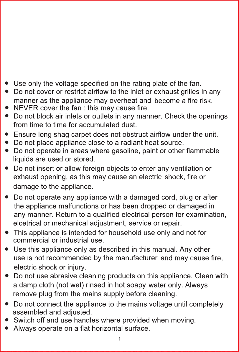
Read all instructions before using this appliance. Carefully retain these instructions for
future reference.
Thank you for choosing a Challenge fan. It is a remarkably versatile product which offers a choice of
air-circulation for summer comfort. This fan has been designed and manufactured to high standards of
engineering and with proper use and care, as described in this leaflet, this appliance will give you years
of useful service.
Please read these instructions carefully.
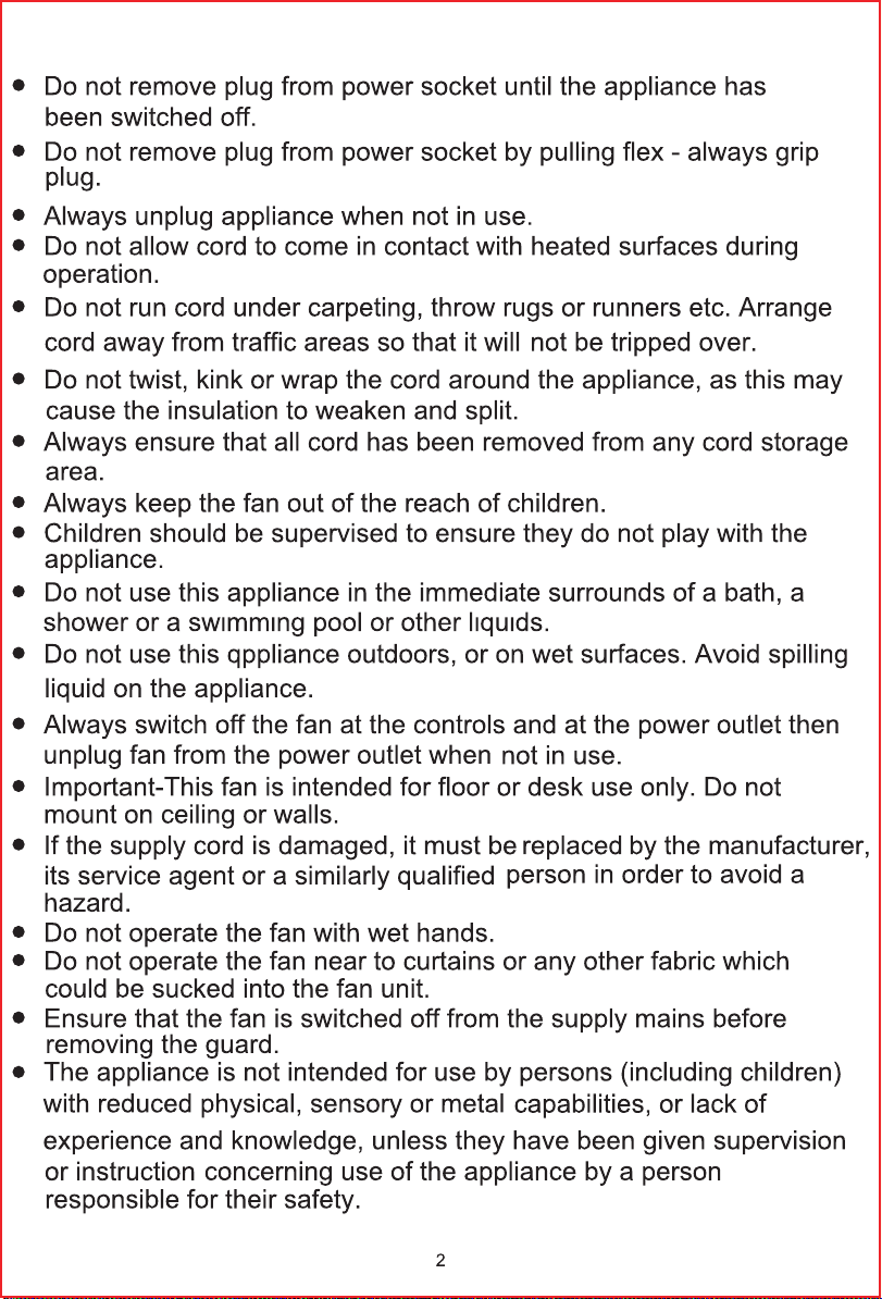
GENERAL CARE AND SAFETY GUIDE
Page 3
Page 4

Page 5

6
4
5
3
1
9
13
2
7
11
10
12
8
14
15
16
17
18
6
Description of parts
6
15
16
17
18
1 Front Guard
2 Locking screw
34Fan Blade
Rear Guard
5 Front Guard Nut (x1)
6 Telescopic Stand
7 Pivot Adjustment Screw
8 Tilt Adjustment Screw
9 Motor Housing
10 On/Off/Speed Control
11 Oscillating Control
12 Motor Spindle
13 Fan Blade Retaining
Screw (x1)
14 Guard Retaining Clips
15 Stand Base
16 Weight
17 Clamping Washer
18 L - Shaped Screw
Assemble Your Metal Stand Fan
Steps:
1. Attach the Telescopic Stand (6) to the Base (15) by placing the Weight (16) on the underside of the base (15)
and the clamping washer (17) in the centre of the weight.Thread the L-Shaped Screw (18) through the assembly
and into the thread in the Telescopic tand (6). Tighten firmly but do not overtighten.
4
Page 6

2. Next attach the motor housing (9) to the top of the telescopic stand (6).First remove all the screws, etc.
7
6
9
8
19
20
7
8
19
8
20
20
19
7
(7, 8, 19 & 20) from the motor housing bracket.
3. Place the Motor Housing on the top of the stand and thread the Large Pivot Bolt (20) through the bracket
and screw in the Small Retaining Screw (8) and tighten (but do not over tighten).
4. Fit the Large Pivot Knob (7) onto the end of the Bolt (20) and the Small Adjusting Knob (19).
Hold the fan motor upright and tighten the Large Pivot Knob (7) and the Small Adjusting Knob (19).
OPERATING INSTRUCTIONS
1. Set the fan on a dry, level and sturdy surface.
2. Plug the fan into the mains.
3. Be sure the voltage of fan conformed to local power condition before using it.
,adjusting angle
1. Push down the oscillation knob to make the fan head oscillate, and pull-up the oscillation knob to stop the fan
head from oscillating.
2. Loosen the adjusting angle knob, adjust the fan to the desired angle, to secure tighten the adjusting angle knob.
Adjust the desired speed by oscillate the power switch:
0--- Stop Ⅰ--- Low Ⅱ--- Medium Ⅲ--- High
5
Page 7

CLEANING AND MAINTENANCE
Your fan reauires little maintenance and contains no user serviceable parts. Do not attempt to dismantle the Fan
Motor body yourself. The fan is permanently lubricated and will not require additional lubrication.
Important: Do not allow water to run into the interior of the fan , as this cause an electric shock .DRY THE FAN
THOROUGHLY with a dry cloth, checking that the fan is completely dry before operating the fan.
Important Safety Instructions
When using electrical appliance, basic precautions should be followed to reduce the risk of fire and personal injury.
6
Page 8

This marking indicates that this product should not be disposed with other household wastes
throughout the EU. To prevent possible harm to the environment or human health from uncontrolled
waste disposal, recycle it responsibly to promote the sustainable reuse of material resources.
To return your used device, please use the return and collection systems or contact the retailer where
the product was purchased. They can take this product for environmental safe recycling.
7
Page 9

CONNECTION TO POWER
Before Switching on make sure that the voltage of your electricity supply is the same as that indicated on the rating
plate.
MAIN CORD
Wiring Instructions: Should it be necessary to change the plug please note the wires in the mains lead are
coloured in accordance with the following code:
BLUE - NEUTRAL
BROWN - LIVE
GREEN AND YELLOW - EARTH
As the colours of the wires in the mains lead of this appliance may not correspond with the coloured markings
identifying the terminals in your plug, proceed as follows:
1. The BLUE wire is the NEUTRAL and must be connected to the terminal which is marked with the letter N or
coloured BLACK.
2. The BROWN wire is the LIVE and must be connected to the terminal which is marked with the letter L or
coloured RED.
3. The GREEN/YELLOW is the EARTH and must be connected to the terminal whick is marked with the letter
E or or coloured GREEN OR GREEN/YELLOW.
4. Always ensure that the cord grip is positioned and fastened correctly.
If a 13A (BS 1363) fused plug is used it must be fitted with a 3A fuse.
If in doubt consult a qualified electrician.
Wiring for a 13 Amp Plug (BS1363)
Please note. The Earth Terminal is marked with the letter E or Earth
symbol
IMPORTANT
As the colours of the wire in the mains lead of this appliance may not correspond with the coloured markings
identifying the terminals in your plug, proceed as follows:
The blue wire must be connected to the terminal marked with the letter N or coloured black.
The brown wire must be connected to the terminal marked with the letter L or coloured red.
The green and yellow wire must be connecting to the terminal marked with the letter E or the earth symbol. ( ).
If a 13 Amp (BS1363/A) plug is used, a 3Amp fuse must be fitted, or if any other type of plug is used, a 3 Amp fuse
must be fitted, either in the plug, adaptor, or on the distribution board.
To prevent electric shock disconnect from the mains
before removing the cover
This unit must be earthed. This equipment must be disconnected from the mains when not in use.
Do not allow thisunit to be exposed to rain or moisture.
Caution
8
Page 10

Technical Specifications
off
Fan sound power level
LWA65,30
dB(A)
Maximum air velocity
c
2,95
meters/sec
Description Symbol Value Unit
Model no. -- --
Voltage -- 220-240 VAC
Insulation class -- Class I --
Maximum fan flow rate F 43,02 m3/min
Fan power input P 35,70 W
Service value SV 1,21 (m3/min)/W
Off mode power consumption P
Measurement standard for service value IEC 60879:1986 (corr.1992)
Contact details for obtaining more information Customer helpline 0345 640 0800
We apologise for any inconvenience caused by any minor inconsistencies in these instructions, which may
occur as a result of product improvements and development.
FD-40M
0 W
9
Page 11

 Loading...