

Page 1

The Challenge Machinery Company provides owner's manuals on its
products s olely as a court esy to i ts cust omers. Se e the inf ormati on belo w
before using this manual.
These manuals are for reference only. These manuals include products which are noncurrent,
unsupported or no longer pr oduced by The Chal l enge M achi nery Com pany , and are pr ov ided sol el y as
an accommodat i on to our c ustom ers. By prov i ding these m anuals, T he Ch al lenge M achi nery Com pany
makes no representation or warranty as to the products, their current condition, or their suitability or
fitness for use in any particular application, which are the sole and i ndependent responsibility of the
product owner and user.
Older produ cts may not co mply with curren t safety pro cedures, guidel ines or regu lat ions, and i t
is the product owner's and user's responsibility to evaluate the suitability and fitness of the
products in their current use and application. The Challenge Machinery Company makes no
representation, warranty or recommendation regarding any modifications which may be
required on non -current o r u nsuppo rted prod ucts. T he Ch allenge Mach inery Co mpan y assumes
no liability for any modification or alteration to any Challenge product, and any such
modification or alteration to any Challenge product is not authorized by The Challenge
Machinery Comp any. The av ailabilit y of t hese manuals is sol el y for t he purpose of provi ding ref erence
information for the products.
This manual may not be complete in all aspects of product maintenance and repair. All products
should be used only by qualified and properly trained personnel, following proper safety
procedures. Al l product s should be regular l y i nspected and m aintai ned, and their condition, appli cation
and use should be periodically evaluated by qualified personnel. Only qualified and properly trained
technicians should perform maintenance, repair and replacement procedures. Attempting these
procedures without pr oper training may cause machine dam age or operat or injury!
Products may be unsup por ted by The Chall enge M ac hinery Company due to age or the unavailability of
parts from their ori ginal m anufactur er. No parts or produc t support will be available to repair or maintain
unsupported prod uc ts. Older products may not be UL listed (if the product does not have a UL l abel it i s
not a listed product), and may not comply with applicable installation or other regulations or
requirement s if rel ocated to a new f acilit y. Many munici palities requi re a product t o be UL l isted bef ore
an electrician will connect power to them. Often the cost of updating an older pro duct to com ply with
current saf ety r egulations is greater than the v alue of t he product .
The Challeng e Machin ery Comp any
6125 Norton Center Drive
Norton Shores, MI 49441-6081 USA
ChallengeMachinery.com
F.254-I-O
February 2014
CHAMPION 305 X, XG, XT
Operator’s Manual
Serial Numbers 07X1360 & Up
Sold and Serviced by
Page 2

1.0 Introduction
1.0 Introductio n
This manual is designed t o help you get the most from your Challenge equipment. Keep this manual
in a safe, convenient place for quick reference by operators and serv ice personnel.
SAFETY ALERT! This symbol means CAUTION: Personal safet y
instructions! Pay special attention to the instructions in bol d ty pe. Personal injury may result if the
precautions are not r ead and followed.
READ THIS MANUAL BEFORE OPERATING! Follow the precautions and instructions given. If
after reading the manual questions still rem ain, contact your Authorized Challenge Dealer.
FOR PARTS AND SERVICE, contact t he Author ized Challenge Dealer from whom you purc hased
the machine. Use the illustrations and parts lists at the back of this manual to identify the correct
parts needed. Always give the SERIAL NUMBER and MODEL of your machine to insure t he correct
parts are sent as soon as possible.
RECORD YOUR MACHINE SERIAL NUMBER in the space provided on the front cover of this
manual. Fill out the warranty c ar d ac c om panyi ng your machine and return it DIRECTLY TO
CHALLENGE.
If you bought a used machine, it is important to have the following information on record at Chall enge.
Copy this page, fill in the information and send it care of The Challenge Serv ice Department, 6125
Norton Center Driv e • Norton Shor es • MI 49441.
CHALLENGE MODEL SERIAL NUMBER
ATTN COMPANY
ADDRESS
CITY STATE/PROVINCE ZIP
PHONE DATE INSTALLED
DEALER NAME & CITY
* WARRANTY INFORMATION *
It is very important that y ou r ead and under st and the conditions outli ned in the Warr anty Information
Sheet att ached to the outside of the shipping cont ainer of your machine.
The Warr anty Inf or m ation Sheet must be filled out completely and returned to THE CHALLENGE
MACHINERY COMPANY in order for the warranty to be issued for this machine.
The Challenge Machinery Company • 6125 Norton Center Dr ive • Norton Shores MI 49417
Copyright© 1997-2014 by The Challenge Machinery Company. All rights reserved. Printed in the U.S.A
2
Challen ge® is a registered trad em ark of
Page 3

1.0 Introduction
TABLE OF CONTENTS
1.0 Introduc tion................................................................................................................................. 2
2.0 Safety.........................................................................................................................................6
2.1 Precautions.............................................................................................................................6
2.2 Power Lockout Proc edur e .......................................................................................................6
2.3 Warning Label Definitions........................................................................................................7
3.0 Packing List.................................................................................................................................9
4.0 Specifications............................................................................................................................10
5.0 Footprint....................................................................................................................................11
6.0 Installation & Setup...................................................................................................................12
6.1 Inspecting Shipment..............................................................................................................12
6.2 Uncrating.............................................................................................................................. 12
6.3 Lifting Instructions.................................................................................................................12
6.4 Moving Instructions............................................................................................................... 13
6.5 Cleaning ............................................................................................................................... 13
6.6 Assembly.............................................................................................................................. 13
6.7 Hydraulic Power Unit Removal.............................................................................................. 14
6.8 Hydraulic Check....................................................................................................................15
6.9 Power Hook-Up.....................................................................................................................15
6.9.1 Three Phase Hook-Up ................................................................................................... 16
6.9.2 Single Phase Hook-Up................................................................................................... 17
7.0 Champion 305 Diagram ............................................................................................................. 18
8.0 Operation X Model .................................................................................................................... 19
8.1 Power – Main Switch.............................................................................................................19
8.2 Table Light ............................................................................................................................ 20
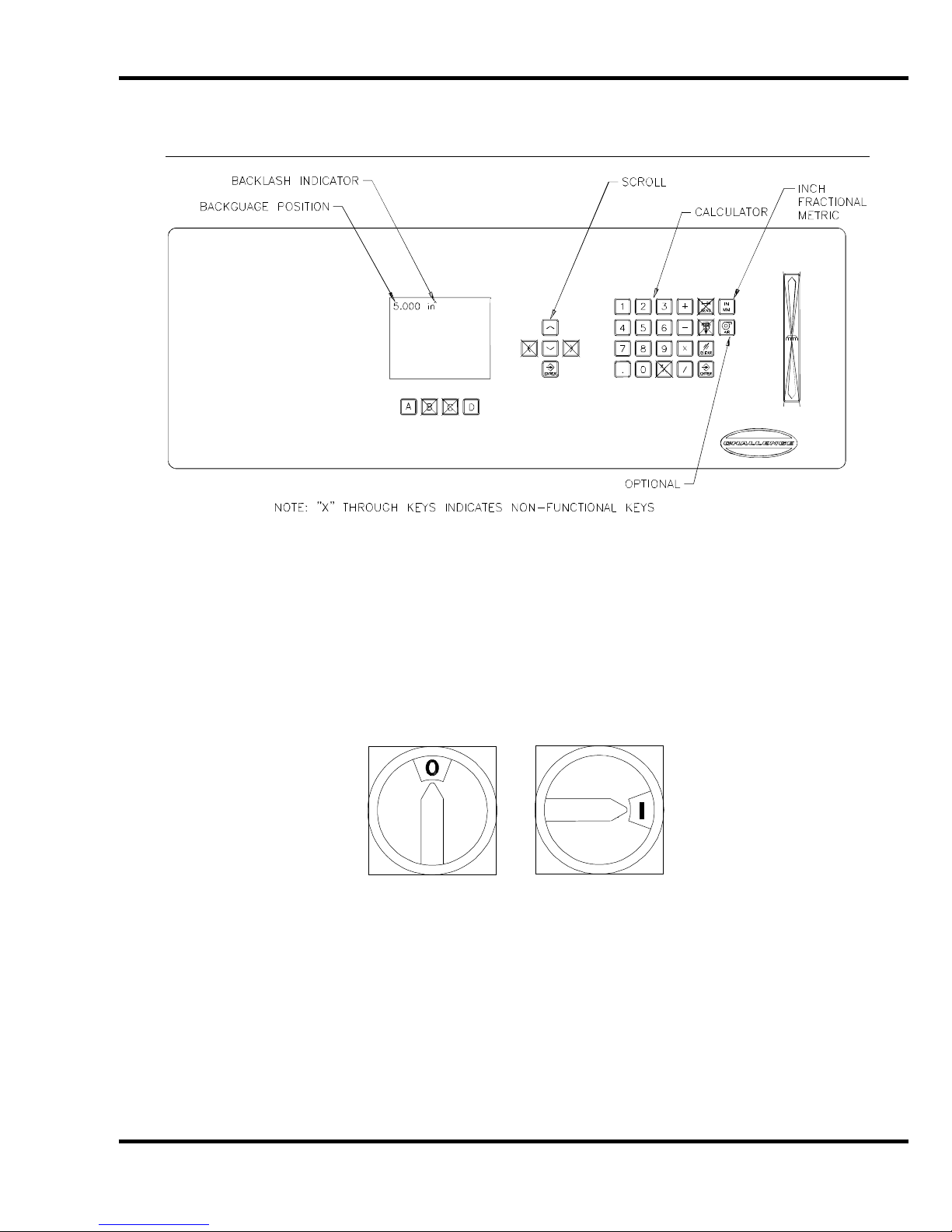
8.3 Presetting the Backgauge ..................................................................................................... 20
8.4 Backlash Indicator.................................................................................................................20
8.5 Backgauge Lock ................................................................................................................... 20
8.6 IN/MM Toggle Soft Key......................................................................................................... 20
8.7 Making a Cut.........................................................................................................................20
8.8 Turning Off the Hydraulic Motor.............................................................................................21
8.9 Jogging Aid........................................................................................................................... 21
8.10 Pre-Clamping...................................................................................................................... 21
8.11 Air Table ON/OFF............................................................................................................... 21
8.12 Adjusting the Clamp Pressure............................................................................................. 22
8.13 Re-calibr ating the Backgauge.............................................................................................. 22
8.14 Knife Down Mode................................................................................................................ 22
8.15 Electric Eyes.......................................................................................................................23
8.16 False Clamp Plate...............................................................................................................23
9.0 Operation – XG Model............................................................................................................... 24
9.1 Using the Machine................................................................................................................ 24
9.1.1 Power - Main Power Switch............................................................................................24
9.1.2 Table Light..................................................................................................................... 24
9.1.3 Start Up......................................................................................................................... 24
9.1.4 Making a Cut..................................................................................................................25
9.1.5 Jogging Aid.................................................................................................................... 25
9.1.6 Adjusting the Clamp Pressure........................................................................................ 26
9.1.7 Pre-Clamping.................................................................................................................26
9.1.8 Knife Change Alarm and Lubrication Alarm .................................................................... 26
9.2 Electric Eyes.........................................................................................................................26
9.3 False Clamp Plate.................................................................................................................26
9.4 Champion XG – Display Panel .............................................................................................. 27
9.5 Definition of Keys.................................................................................................................. 27
3
Page 4

1.0 Introduction
9.5.1 Backgauge Glide Control................................................................................................27
9.5.2 IN/MM Key......................................................................................................................27
9.5.3 Air Ta b le ON / OFF Key....................................................................................................27
9.5.4 Send Key........................................................................................................................27
9.5.5 Push-Out Key.................................................................................................................28
9.5.6 Clear Key........................................................................................................................28
9.5.7 Enter Key........................................................................................................................28
9.5.8 Priority Add (X/Y) Key.....................................................................................................28
9.5.9 Soft Keys........................................................................................................................28
9.5.10 Arrow Keys...................................................................................................................28
9.5.11 Contrast Control (Only on Serial numbers 10x1535 and below).....................................29
9.5.12 Contrast Control (For Serial numbers 10x1536 and up).................................................29
9.6 Manual Backgauge Cont r ol....................................................................................................29
9.6.1 Backgauge Glide Control................................................................................................29
9.6.2 Backgauge Cont rol Knob................................................................................................29
9.6.3 Backlash Indicator..........................................................................................................29
9.7 Send Mode............................................................................................................................30
9.7.1 Entering Math.................................................................................................................30
9.7.2 Entering Fractions...........................................................................................................30
9.8 Repeat Mode.........................................................................................................................31
9.9 Maintenance Mode ................................................................................................................31
9.9.1 Language .......................................................................................................................31
9.9.2 Parameters.....................................................................................................................32
9.9.3 Diagnostic.......................................................................................................................33
9.10 Job Mode.............................................................................................................................34
9.10.1 Lock/Unlocking a Job....................................................................................................34
9.10.2 Copying a Job...............................................................................................................34
9.10.3 Erasing a Job................................................................................................................34
9.10.4 Creating a New Job......................................................................................................35
9.10.5 Editing an Existing Job..................................................................................................39
9.10.6 Running a Programmed Job .........................................................................................40
9.10.7 Exiting a Job.................................................................................................................40
9.11 An Example Job – XG Model ...............................................................................................40
10.0 Operating Tips.........................................................................................................................42
11.0 Knife Installation/Changing.......................................................................................................43
11.1 Knife Removal.....................................................................................................................44
11.2 Knife Installation..................................................................................................................45
11.3 Using the Shielded Knife Lifter.............................................................................................46
11.4 False Clamp Plate................................................................................................................47
11.5 Knife Care Basics................................................................................................................48
11.5.1 Cut Quality....................................................................................................................48
11.6 Bevel Angle.........................................................................................................................49
11.7 Helpful Suggest ions.............................................................................................................49
11.8 Knife Care............................................................................................................................50
12.0 Lubrication...............................................................................................................................51
12.1 Hydraulic System.................................................................................................................53
12.2 Recommended Oils .............................................................................................................54
12.3 Changing the Oil..................................................................................................................54
13.0 Operator Adj ustm ents/Cleaning................................................................................................56
13.1 Line Lights...........................................................................................................................56
13.2 Manual Pr essure Reducer – (305X Only).............................................................................57
13.3 Operator Cleaning................................................................................................................58
13.3.1 Hydraulics.....................................................................................................................58
13.3.2 Table Conditioning........................................................................................................58
13.3.3 Console........................................................................................................................59
4
Page 5

1.0 Introduction
13.3.4 Machine Base.............................................................................................................. 59
14.0 Program Log........................................................................................................................... 60
15.0 Channel Log ............................................................................................................................ 61
16.0 Safety System Tests............................................................................................................... 62
5
Page 6

2.0 Safety
2.0 Safety
2.1 Precautions
• This machine i s designed f or one- per son operation. Never operate the machine with more than
one person.
• Safe use of this machi ne is the r esponsibility of the operator . Use good judgment and common
sense when working with and around this machine.
• Read and understand all instructions thoroughl y before using the machine. If questions remain,
contact the deal er from whic h y ou purchased this machine. Failure to under stand the operating
instructions may result in personal injury.
• Only trained and aut hor iz ed people should operate this machine.
• Do not alter saf ety guar ds or devic es. They are for your protection. Severe personal injury may
result.
• Disconnect power bef or e cl eaning or performing mai ntenance. See S ection 2.2 Power Lockout
Procedure.
• Observe all cauti on labels and plates on this machine.
• Be sure the cutter i s properly grounded.
• Be sure there is sufficient power to operate the cutter properly.
• Keep foreign objec ts off the table and away from cutter blade.
• BE EXTREMELY CAREFUL when handling and changing the cutter knif e. Severe lacerations or
dismemberm ent could result from careless handling pr oc edur es.
• Keep the floor around the cutter free of trim, debris, oil and grease.
• When replacing hy dr aulic parts, loosen the connections slowly to release pressure. Never loosen
connections with the machine running.
• If the cutter sounds unusual or operates abnormally, turn it off and consult the troubleshooting
section of thi s manual. If the problem cannot be corrected, have it chec k ed by a qualified service
person.
• CRUSH HAZARD, keep hands and fingers from under the clamp while clam ping. Use Jogging
Aid to load paper, and use the back gauge to push paper out before unloading. DO NOT REACH
UNDER THE KNIFE AND CLAMP AREA!
2.2 Power Lockout Procedure
For maximum safety when m aki ng adjustments or repairs to your machine, be sure to lock out the
main power control switch to which the machine is connected. The switch should be moved to the
OFF position and a padlock placed in the loop. The person servicing the machine should hold the
key.
6
Figure 1
Page 7
2.0 Safety
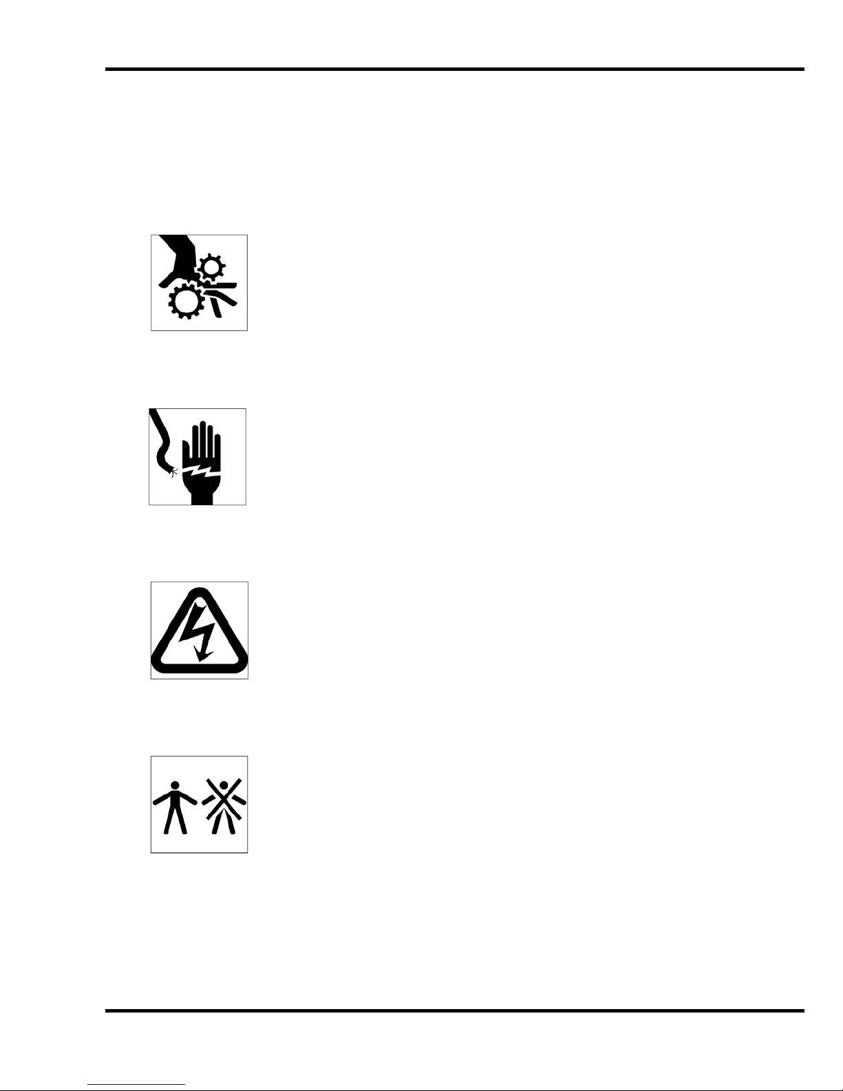
2.3 Warning Label Definitions
The following warni ng labels are found at various loc ations on your machine. Read and understand
the meaning of each symbol. If a label is lost from the machine, it should be replaced. The item
number and locati on of each label can be found in Section 17.0, Schem atics and Parts List.
HAZARDOUS AREA
Disconnect power bef or e cl eaning, servicing, or m aki ng adjustm ents not requiring
power. Do not alter saf ety guar ds or devices; they are for your prot ection. Replace
all guards. Do not operate with any guards removed.
SHOCK HAZARD
Disconnect power bef or e r em ov ing cover. Replace cover before operation.
SHOCK HAZARD
Disconnect power bef or e r em ov ing cover. Replace cover before operation.
SINGLE OPERATOR
Do not operate with m or e than one person.
7
Page 8

2.0 Safety
!OJO!
This Este simbolo de alerta de seguridad significa ¡ OJO ! INSTRUCCIONES DE SEGURIDADPERSONAL. Lea las i nstrucciones po rque se refieren a su
seguridad personal. Fall de obedecer las instrucciones que siguen podria resultar en lesiones
corporales.
• Esta maquina, junto con sus mecanismos de seguridad, esta disenada para ser manejada por
• UNA SOLA PERSONA a la vez. Jamas debe ser manejada por mas de una persona al mi smo
• tiempo.
• La seguridad es la responsabilidad del operario que usa esta maquina.
• LEA DETENIDAMENTE el manual de instrucciones y las PRECAUCIONES DE SEGURIDAD
antes de poner a funcionar la c or tadora. Pidale a su supervisor una copia.
• El manejo de la guill otina debe estar exclusivamente a cargo de per sonal entrenado y autoriz ado
para ello.
• NO MODIFIQUE LOS MECANISMOS DE SEGURI DAD, estan ahi para su proteccion no deben
ni modificar se ni quitarse.
• DESCONECTE LA CORRIENTE ELECTRICA antes de proceder a hacerle servicio de limpieza,
engrasar, o de hacer adjustes que no requieren corrient e. Trabe el interruptor en la posicion
OFF (apagado); vea “Procedimiento para cortar la corriente elect ri c a” al pi e de esta pagi na.
• Eche llave a la guillotina y quite la llave cuando la maquina no esta en operacion; vea “Corriente
electrica”.
• Asegurese de que la guillotina este debidament e a tierra. V ea “Conexion de la fuerza electrica”.
• Verifique el v oltaje y asegurese de que este sea suficient e par a el debido funcionamiento de la
guillotina.
• Preste atenci on a todas las pl ac as con advertencias instaladas en esta guillotina.
• No permita que objetos estranos esten en la mesa o cerca de la cuchilla cort ador a.
• TENGA SUMO CUIDADO al tocar y cambiar la cuchilla. Heridas severas y hasta
desmembrami ento pueden resultar del manejo sin cui dado o negligente.
• El suelo alrededor de la guillotina debe mantenerse despejado y libre de recortes, desperdi c ios,
aceite y grasa.
• Al haber la necesidad de r eem plazar partes hidraulic as, afloje todas las conexiones poco a poco
para dejar escapar l a pr esi on. Jamas debe aflojarse conexiones mientras la maquina este
• andando.
• Si la guillotina empezara a sonar o trabajar difer entemente a lo acostumbrado, desconectela y
consulte la seccion “Troubleshooting” ( Reparador) de este manual. Si no es posible corregir el
problema, llam e a su servi ci o autorizado para que le examinen la maquina.
• PELIGRO DE MACHUQUE - Mantenga manos y dedos f uer a de la agar r ader a mi entras sujeta el
papel. Use el calibr ador trasero y su rueda de mano para empujar el papel cortado. NO PONGA
SUS MANOS BAJOLA CUCHILLA O AREA DE LA AGARRADERA.
• NO OPERE SIN LAS GUARDAS PROTECTORAS!
¡ OJO ! PRECAUCION - Como proceder para desco nect ar
la corriente electrica.
Para maxima seguridad durante ajustes y reparaciones de su maquina, verifique bien que el interruptor principal
de control de corriente al cual la maquina esta conectada, este desconectado. El interruptor deba ser puesto en
la posicion “OFF” (desconectado) y se debe poner un candado en la anilla. La llave del candado debe ser
guardada por la persona que estara efectuando los trabajos de servicio o de reparacion en la guillotina.
Desconecte la corriente electrica antes de proceder a hacer cualquier ajuste o reparacion o de efectuar el
engrase en cualquier maquina.
8
Page 9

3.0 Packing List
3.0 Packing List
Part No. Description Qty.
Basic Machine 1
Extension Side Tables:
47166 18 x 24 Steel Side Table 2
47164-1 Side Table Back Plate 2
H-6913-606 Side Table Bolts 8
H-6424-6 Side Table Hex Nuts 8
H-6939-616 Leveling Screws 4
H-6913-6008 Side Table Mounting Bolts (shipped installed) 4
H-7321-6 Side Table Mounting Washers (shipped i nstalled) 4
47006-2 False Clamp Plate (shipped installed) 1
47507 Knife 2
H-6918-608 Knife Bolts 6
8815 Knife Washers, Special 6
4171 Cutting Sticks (one installed) 4
47575 Knife Lifter Assembly 1
A-12608-4 Jogging Aid 1
Tool Kit:
5064 Cutting Stick Puller 1
W-164 Hex “T” Wrench 1
W-158 5/16 Open End Wrench 1
W-141 1/8” 1
W-137 5/32” 1
Fuses:
E-2308 3.2 A (X, XG Series) 1
E-2330-7 5 A S.B. (X, XG Series) 1
E-889-35 1 A S.B. (X, XG Series) 1
E-889-5 4 A S.B. (X, XG Series) 1
E-889-9 8 A S.B. (X, XG Series) 1
E-2330-8 6.3 A S.B. (XG Series) 1
E-2330-3 2 A S.B. (XG Series) 1
9
Page 10

4.0 Specification s
4.0 Specificati ons
Description Inch Units Metric Units
Cutting Width 30 ½” 77.5 cm
Clamp Opening 4” 10.2 cm
Clamping Force 400-5000 lbs. 1.8 – 22 kN
Minimum Cut – Standard ¾” 1.9 cm
- Special ½” 1.3 cm
- w/ False Clamp Plate 2” 5.1 cm
Table Space
Front: (std.)
Back:
Dimensions
Table Height 36 ½“ 92.7 cm
Overall Height 58 ½” 148.6 cm
Overall Length 69 ½” 176.5 cm
Overall Width 48 ½” 123 cm
w/ Side Tables 78 ½” 200 cm
w/o Side Tables 48 ½” 123 cm
Approx. Net Weight 2550 lbs 1157 kg
Approx. Shipping Weight 2750 lbs 1247 kg
Will pass through door:
Assembled 49” 125 cm
Table/treadle out 42” 112 cm
Table/treadle/pwr unit out 24-1/2” 63 cm
Electrical
Standard: 5 HP, 3 Phase, 60 Hz AC; 208/230V, @ 25A or 460V @ 11.5A
Optional: 5 HP, Single Phase, 60 Hz AC; 208V, @ 44A or 230V @ 44A
3 Phase, 50 Hz AC; 220V or 380V
Single Phase, 50 Hz AC; 220V
Spacer
XD & XG series spacer has 9801 cuts on 99 channels.
XT series spacer has 47000 cut positions within the machine. (Unlimited with USB
Port.)
Minimum space between cut positions is 0.005” or 1mm. Repeat positioning accuracy is
0.003” or 0.05mm.
Electri c Eyes –
Response time = 68 ms
Object detection capability = 12 mm
Challenge reserves the right to make changes to any product or specif ication without notic e and
without inc ur ri ng r esponsibility to existing units.
25”
30 ½”
63.5 cm
77.5 cm
10
Page 11
5.0 Footprint
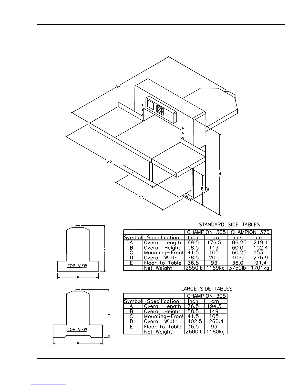
5.0 Footprint
11
Page 12

6.0 Installati on & Setup
6.0 Installation & Setup
6.1 Inspecting Shipm ent
This machine has been carefully packed to prevent damage during shipment. However, claim s f or
damage or loss are the responsibility of the recipient. Inspect all shipment s as soon as they are
received. If there is any noticeable damage, note it on the fr eight bill. Visual and/or hidden damage
must be report ed to the claims department of the carrier within 15 days. Contact your dealer if you
need any assistance. Check the contents of the box against the packing list on page 9. Make sure
there are no missing items.
6.2 Uncrating
This machine i s lagged to a wood skid and covered with a triple-walled cor r ugated container. Loosen
the flaps of the carton where they ar e attached to the skid. When loose, the carton c an be lift ed
straight up. Remove t he side tables and accessory box, which are also attached to the skid. Place
the cutter/skid about where the machine will be positioned and remove the lag screws from the ski d.
6.3 Lifting Instructio ns
Unpacking, handling, and positioni ng shoul d be done by prof essional riggers. If handling or
unpacking is a problem, your dealer or a local trucking facility should be able to supply or recomm end
a qualified rigger. This 2550-lb/1157-kg m achi ne should be moved with experienced people and t he
proper equipment. Do not risk personal injury or damage by att em pting to move machinery with
inadequate equipm ent or manpower.
Champion cutt ers may include an opt i onal bloc k for lifting t he machi ne. Remove the prot ective cov er
from the rear of the arch. Install t he block with the h ole up. Use a hook and chain or lifti ng straps
rated at 3000-l b/1360- kg or higher. Carefull y lift the machi ne off its skid, and remov e the skid. Place
the machine on the fl oor .
Lifting str aps may also be u sed to lif t the m achine by placi ng the straps arou nd the f ront and rear of
the table. When straps are used i n this way, wood blocks must be pl aced beside the lead screw to
prevent dam age, (Figure 2). A bent lead screw will cause the backgauge to bind.
Figure 2
The backgauge shoul d be po siti oned all the way to th e fr ont of the t able and straps placed a s clo se
the machine body as possible. Gently lift the cutter, r em ov e the skid and caref ully place the cutter on
the floor.
Once the machine is off its skid, it can be moved with a forklift or pallet jack.
12
Page 13

6. 0 In st all ation & Setup
6.4 Moving Instructi ons
Use a forklift or pallet jack to move the machine from the front. Do not attempt to lif t f r om the si des or
rear.
6.5 Cleaning
Wipe down the table and bare m etal surfaces with a non-flammable solvent such as CRC or blanket
wash. The table surf ac e is cast iron, and it will rust if left unprotected. Coat t he table with a nonabrasive wax. A Cutt er Care Kit, p/n 16077, with cleaner and wax, is av ailable through your
Authorized Challenge Dealer. The protective film on the console may be removed. Never clean
console with petroleum based solvents. Damage will result . Also see, Operator Cleani ng, pg. 58.
6.6 Assembly
Unless otherwise speci fied, the only items t hat have been disassem bled for shipping are the knif e,
Reach-Around shiel ds on the electric eyes and extension tables. Knife installati on wil l be c ov er ed
later. Extension table attachment follows.
NOTE: Extension tables are heavy. Use two people to attach them to the machi ne.
1. Assemble the back stops to the extension t ables. The extension table bolt s and hex nut s are
packed in the tool kit box. Tables are installed with the clearanc e hole for the knife gibs
towards the center of the cutter.
2. One person should hold the extension t able in position while the other aligns the holes and
starts threading the mounting bolts with washers. The mounting bolts are shipped installed in
the side of table- remove them to install tables.
3. Use a 9/16” socket and extension to snug tight en the mounting bolts, then tap the ext ensi on
table up or down with your hand or a rubber mallet until it is flush with the main table. Run a
straight edge or sheet of paper over the seam to check the fit. Make sure your stock will not
catch on the seam.
4. Insert the leveling setscrews into t he threaded holes next to the mounting bolts. You may
have to loosen the mounting bolts slightly to allow enough pl ay to level the table. After the
extension tables are leveled and the surface joint s even, tighten the mounti ng bolts securely.
5. The extension tables are powder-coated and need only be wiped down with a dry cloth. DO
NOT apply solvents or abrasive cleaners to extension table surfaces. They may cause
discolorat ion or scratches.
NOTE: The Reach-Around S hields for the electric eyes are in thei r shipping positions – follow the
instructions below to secure them in the operational position.
1. On t he bottom of the electric eye housing – loosen the screw closet to the machine. Do not
remove the screw
2. On t he bottom of the electric eye housing – loosen and rem ove the other two screws – rotate
the shield back out of t he c ut area. Line up the holes and re-install the screws – tighten all
screws (See the i nstr uc tion sheet included in the shipping material for more details).
ATTENTION
POTENTIAL CRUSH/LA CE RATIO N HAZZARD – THE SHIELDS AR E THERE FOR YOUR SAFETY.
: FAILURE TO INSTALL THE REACH-AROUND SHIELDS COULD CAUSE A
13
Page 14

6.0 Installati on & Setup
6.7 Hydraulic Power Unit Removal
If install ati on requi res that t he machi ne pass throu gh a door way that i s les s than 49” but great er t han
or equal to 42” wide, the machine should have been ordered from Challenge “k noc k ed down” with the
table rem oved. If the m achine must fi t through a doorway that is less t han 42” and greater than or
equal to 24-1/2” , the hydr aulic power unit m ust be remov ed on-site. T o remov e the hydrauli c power
unit, follow the instructions below.
1. Disconnect the electrical c onduits to the hydraulic motor, air blower, and hy dr aulic cooling
fan, junction box.
2. Locate the hose that connects the manifold to the oil filter. Disconnect it from the filter.
Disconnect the hy dr aulic pump hose from the manifold. Att ac h the hose that was connected
to the manifold to t he oil filter. Attach the hose that was connected to the filter to the
manifold. This will mi nimi z e oil leak age. After the unit is install ed, rec onnec t the hoses to
their original location.
3. Rem ov e the filler cap and use a transfer pump to remove the hydr aulic fluid into buckets.
4. Rem ov e the ( 4) bolts that attach the hydraulic assembly t o the cutter base. They are located
at the bottom shelf t he base.
5. USE EXTRE M E CAUTION WHILE REMOVING THE POWER UNIT. It is very heavy and
should be removed usi ng a fork truck. CAUTION, the machine will be top heavy and m ay tip
easily with the power unit removed. Move the reservoir thr ough the doorway on its side.
6. DO NOT ATTEMPT TO LIFT THE CUTTER BY PLACING STRAPS OR THE FORKS OF A
TRUCK UNDER THE CLAMP. This can damage the machine.
7. Reinstall the power unit, conduits, hoses, after the machine i s in position. Refill the hydraulic
reservoir.
14
Page 15

6. 0 In st all ation & Setup
6.8 Hydraulic Check
The hydrauli c r eservoir is fill ed with 13-1/ 2 gal lons of ISO VG 46 hydr auli c oil at the f actory . The fl uid
level should be check ed during i nstallati on, and at least onc e per week during norm al operati on. The
reservoir is located behind the cutt er, beneath the tabl e (Figure 3). The hydr aulic tank has a sight
gauge in the rear for c hec ki ng the oil level. The reservoir should be kept full at all times.
Sight
Gauge
Figure 3
NOTE: DO NOT OVERFILL. Overfilling m ay cause leak age when the machine is hot.
6.9 Power Hook -U p
For satisfact ory oper ation, be sure that your cutt er is wired for the correct phase and v ol tage and has
adequate power. The c orrect elect rical specifi cations for your machine are shown on the seri al plate.
Check the machine serial plate before connecting the power. For future reference, transfer this
information to the front cover of this manual.
Watch Setup Voltage- Inadequate power to the cutter can be a major source of problems. Too
many machines on the same circuit will reduce the power to each machi ne. Inadequat e volt age will
cause ov erheating, loss of power, and in ex treme cases, f ailure to operat e. Test li ne voltage when
the shop is at actual working levels. Challenge recommends a dedicated line with a lockable
disconnect to pr ov ide adequate power for this machine.
CAUTION: SHOCK HAZARD! Always disconnect power at main
power panel befo re working on the cutter. Lock it out to prevent accidental power up. (S ee
Power Loc kout Procedure pa ge 6).
Important: You must have an adequ ate size c ir cuit and heavy enough wiri ng f or t his mac hine. T he
circuit size should be a minimum of 20% greater than the amperage rating on the machine
nameplate. If a wire is run over 75 feet ( 23 meters), the next siz e wire should be used. Check local
electric al c odes.
15
Page 16
6.0 Installati on & Setup
Electrical Specifications for Champion Cutters
Volts Amps Circuit Size Wire Size Metric Wire
3 Phase: 460 V 11.5 20 A #12 AWG 4mm sq.
230 25 35 #8 10mm sq.
208 25 35 #8 10mm sq.
1 Phase: 230 37 44 #6 16mm sq.
208 38.7 44 #6 16mm sq.
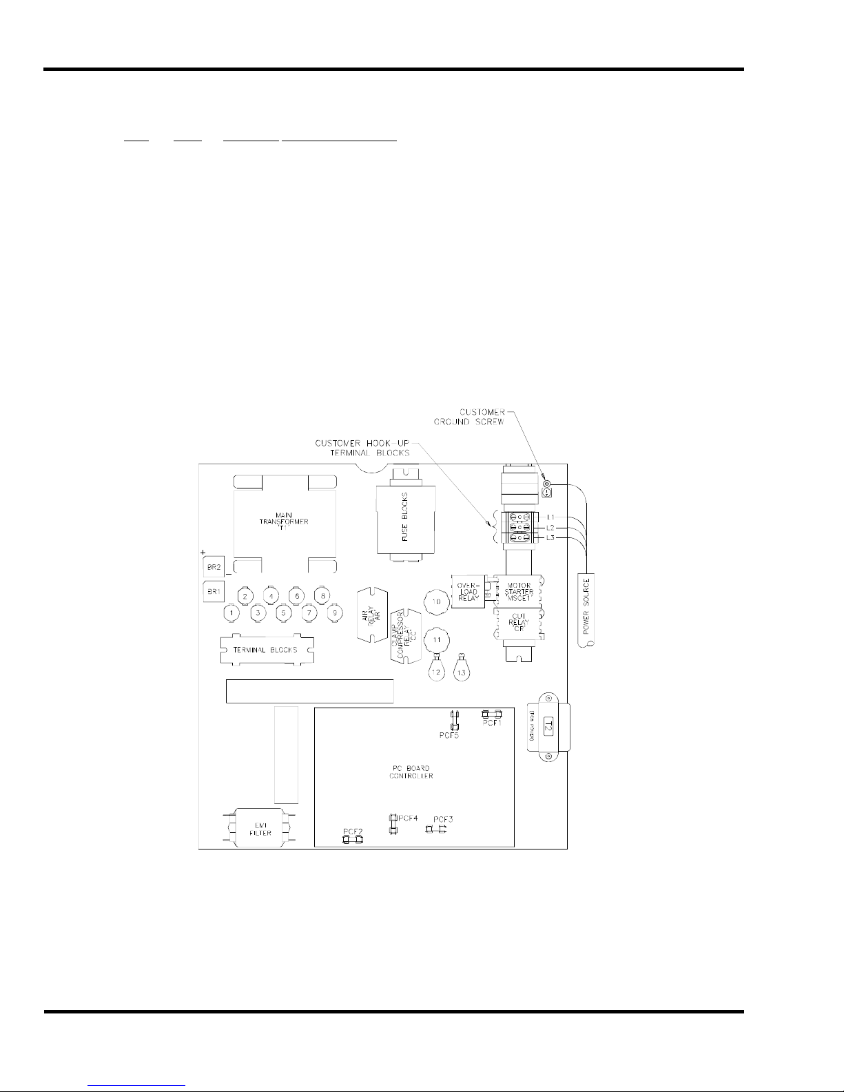
6.9.1 Three Phase Hook-Up
The power source is connect ed to the cutter through the bott om of t he power panel (right hand side).
1. DISCO NNE CT AND LOCK OUT THE POWER at the main panel to prevent accident al power
up. (See Power Lockout, page 6).
2. Thread the power cord through a conduit connec tor into the power panel.
3. Fasten the ground lead to the ground terminal lug (Figure 4).
4. Fasten the three power leads to the thr ee termi nals of the main power terminal block - L1, L2,
& L3.
5. Close the electrical panel doors and l atch them. Unlock the main panel and turn on the
power. Turn on the main power disconnect switch located on the front face of the table.
16
Figure 4
Page 17

6. 0 In st all ation & Setup
6. Press both cut buttons simultaneously to activate the motor and check to make sure it is
turning the same dir ec tion as the arrow on the motor casing.
If it is not turning the proper direction, disconnect the power and exchange any two leads of the power
cord as in Figure 5.
1
2
31 2
3
Figure 5
6.9.2 Single Phase Hook-Up
The power source is connect ed to the cutter through the bott om of t he power panel (right hand side).
1. DISCO NNE CT THE POWER AND LOCK IT OUT at the main power panel to prevent
accidental power up. ( S ee P ower Lockout, page 6).
2. Thread the power cord through a conduit connec tor into the power panel.
3. Fasten the ground lead to the ground terminal lug, (Figure 4 on page 16).
4. Fasten the two power leads to the L1 and L2 terminal s of the m ain termi nal block.
5. Close the electrical panel doors and l atch them. Unlock the main panel and turn on the
power. Turn on the main power disconnect switch and simult aneousl y pr ess both cut buttons
to start the hydraulic motor.
17
Page 18
7.0 Champion 305 Diagram
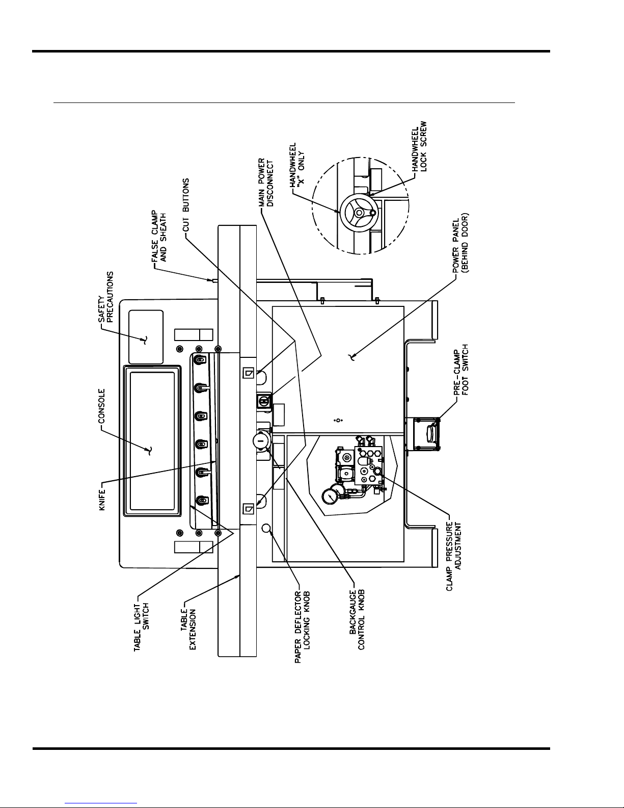
7.0 Champion 30 5 Diag r am
18
Figure 6
Page 19
8.0 Operation X Model
8.0 Operation X Model
Figure 7
IMPORTANT: DO NOT ATTEMPT TO OPERATE THE CUTTER UNTIL YOU HAVE THOROUGHLY
READ AND UNDERSTAND ALL OF THE FOLLOWING INSTRUCTIO NS. CALL YOUR
AUTHORIZED CHALLENGE DEALER IF YOU STILL HAVE ANY QUESTIONS.
8.1 Power – Main Switch
Power is applied t o the mac hine when the main power switch is turned to t he “ON” position (Figure 8).
The display and line lights are turned on at this time.
OFF ON
Figure 8
The display and line lights will shut off after 2 minutes without any activity. To restore power to the
display and line li ghts, press either cut button.
19
Page 20

8.0 Operation X Model
8.2 Table Light
The table light is turned on and off using a switch located under the ar c h (Figure 6, page 18). The
table light will also turn on and off with the main power, provided t he table light switch is in the “on”
position.
8.3 Presetting the Backgauge
The backgauge must be preset every time the power is turned on. Using the hand wheel, turn the
backgauge until it passes forward through the 5” position. The display readout will then show the
correct back gauge posi tion.
8.4 Backlash Indica to r
A small carat will be displ ay ed nex t to the backgauge position if the back gauge was last moved
backward. To insure accurat e c uts, always approach the desired backgauge position from behi nd
(moving the backgauge forward).
8.5 Backgauge Lock
Tightening the backgauge lock prevents the bac k gauge from mov ing while positioning paper against
it. The Champion X model has a thumb screw l oc k beneath t he hand wheel, (Figure 9).
Thumb Screw
Lock
Figure 9
8.6 IN/MM Toggle Soft Key
This switch will toggle the display readout bet ween inc hes, fractions, and millimet er s. It can be f ound
on the console as shown in Fi gur e 7, on page 19.
8.7 Making a Cut
Place the paper agai nst the backgauge and left side guide. Press and release both c ut buttons once
to start the hydraulic motor. Then press and hold both cut buttons to start the cut cycle. While
holding the cut butt ons, the knife and clamp will complete t he c ut cycle. If the buttons are released at
any time during the c ycle, the knife and clamp will immediately return to the up position.
Note: Both cut butt ons must be released before a new cut can be made. The cut buttons must be
pressed withi n 1/2 second of each other both to start the hydraulic m otor and to make a cut.
20
Page 21
8.0 Operation X Model
DO NOT ATTEMPT TO REMOVE TRIM UNTIL THE KNIFE AND CLAMP
HAVE STOPPED IN THE UP POSITION! Due to static buildup, fine trim may have a tendency to
stick to the clam p or knif e surf ac es. Finger tips might be drawn into the knif e by the cl am p if this is
attempted. Wait until the knif e and cl am p hav e BOTH STOPPED MOVING before removing stock
trim.
8.8 Turning Off the Hydraulic Motor
The hydraulic m otor will turn off after 2 minutes without any activ i ty. The hydraulic motor can also be
shut off manuall y by pressing and hol ding the left cut button.
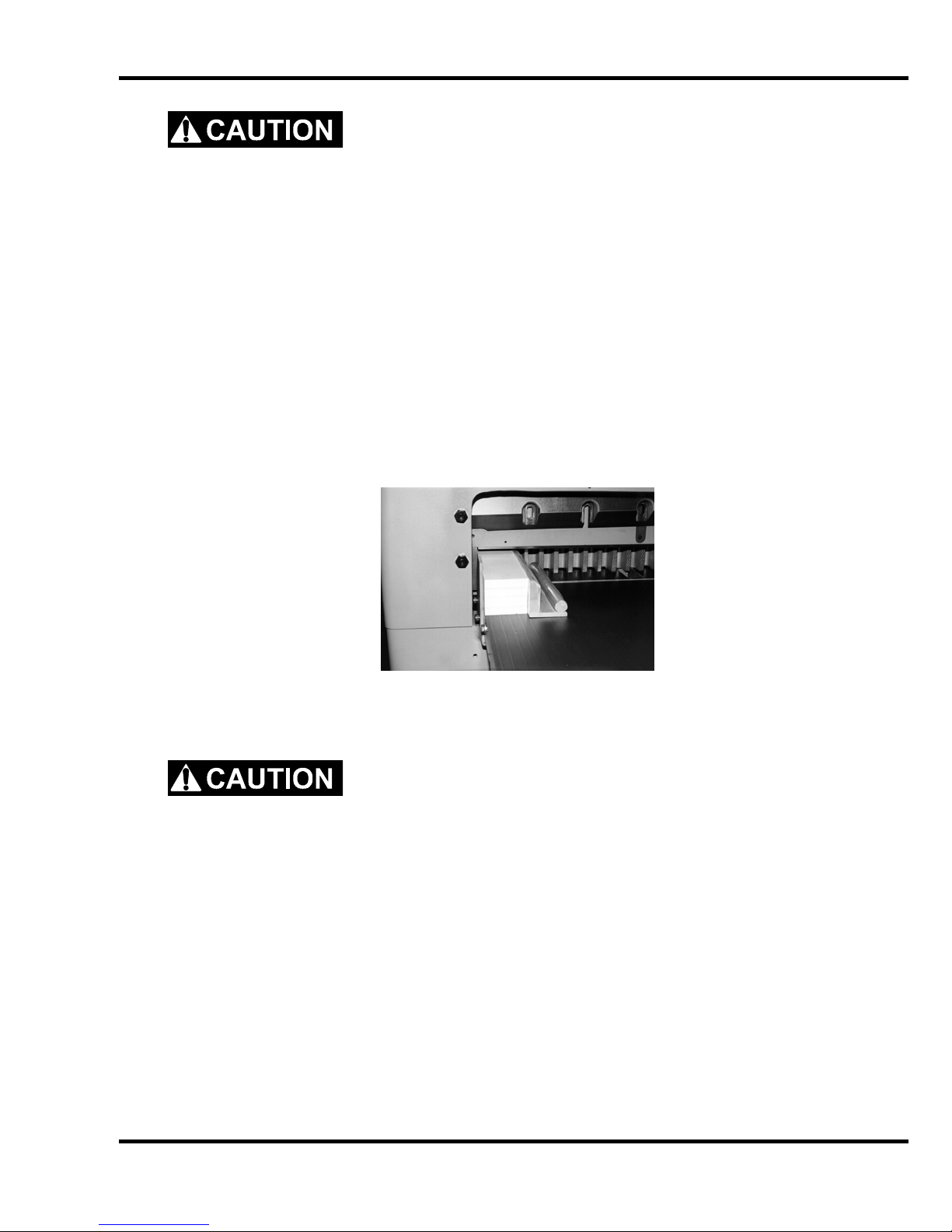
8.9 Jogging Aid
All Champion cutter s i ncl ude a jogging aid as standard equipment. The jogging aid allows the
operator to load and align stock without placing hands or arm s under t he cl am p and k nife area.
Load and align the paper against the side guide, (Figure 10), then square it to the backgauge for
cutting.
Figure 10
Additional j ogging aids can be purchased by contacting your authorized Challenge deal er .
Always remove the joggi ng aid from the table before making a cut.
8.10 Pre-Cl am ping
All Champion cutter s are equipped with a low pressure clam ping feature which allows the operator to
clamp paper bef or e beginning the cut cycle. To use this feature, press the footswitch until t he cl am p
comes down on the paper. While holding the foot switch down, press the cut but tons. Release it
once the cut has been completed. Although this is low pressure clamping, avoid placing hands under
the clamp at al l ti mes.
8.11 Air Table ON/OFF
If your machine i s equi pped with an air table, it can be turned on and off by pr essing t he soft key
shown in figure 7, page 19.
21
Page 22

8.0 Operation X Model
8.12 Adjusting the C lam p Pressure
DO NOT set the clamp pressure below 300 p si. Pressures below this
will not allow the auto-cycle to operate properly, and the kni f e will come down before the
clamp. Severe lacerations and stock spoilage could result.
A pressure reducer valve and gauge located inside the lef t door housi ng on the front of the cutter
below the table. By adj usting the pressure reducer valve, clamping pressure can be set (see
Hydraulic Adjustments section) to a maximum of 1400 psi for heav y stoc k or large reams to a
minimum of 300 psi f or pressure sensi tive jobs like carbon or NCR sets. For pressure sensit ive stock
using the fal se clamp plate is also recommended.
8.13 Re-calibrating the Backgauge
If the backgauge posit ion readout does not match the actual measurement between the knife and the
backgauge, the cutter must be re-calibrated. This i naccurac y c an oc c ur due t o r ough handling during
shipment.
The accuracy can be check ed by comparing cut sheets of paper. This process is described below.
NOTE: The bac k gauge gibs should be adjusted and t he bac kgauge squared before attempting to re-
zero, see Adjustments.
1. Place a 1/4 to 1/2 inch (5 to 13mm) pile of 8-1/2 X 11 (A4) paper against the center of the
backgauge.
2. Trim cut lengthwise and rotate 180
up to the 10" (254mm) position and make a cut. Move the backgauge up to 5" (127mm) and
make another cut.
3. Take several sheets from the cent er of each lift and compare them to each other. The
encoder system on your cutter will space accurately between your 10” (254mm) and 5"
(127mm) cuts, whether the overall accuracy is corr ec t or not. The stack of paper bet ween
the 10” (254mm) and 5" (127mm ) cuts will be a true 5", but the paper left against the
backgauge will not- if the backgauge position r eadout is off.
4. If the bac k gauge posi tion readout is off, you will have to adjust the accuracy. This parameter
provides a means for adjusting the accuracy of the backgauge. To change the accuracy,
send the backgauge to 2 inches (50.8mm) and cut paper. Measure the paper, and type in
what you actually measure. The computer will calculate the am ount of error and will
compensate. The amount of error could also be added to or subtract ed from the value
already displayed. Press “A” for Maint. Scroll to Param eters and Ent er . Scroll to Accuracy
Adjust and enter the measured value.
6. Run the back gauge back, then bring it forward thr ough the 5" (127mm) pre-setter again and
make another test.
0
. Using the backgauge position r eadout, bring the paper
8.14 Knife Do wn Mo de
The knife down mode is used to send the knife and clamp to the down position without returning up.
This provi des a way for the servi c e technician to change the knife. To send the knife down or up,
enter maintenance m ode, “A”. Select either Knife Down or Knife Up, and then press the cut buttons.
When sending the knif e down, t he c ut but tons must be held until the motor stops.
22
Page 23

8.0 Operation X Model
8.15 Electric Eyes
The electric ey es prevent reaching into the cutti ng ar ea while a c ut is being m ade. If the beams are
broken while a cut i s bei ng made, the knife and clamp will return to the up posi tion.
8.16 False Clamp Plate
The false clamp plate should be stored in its sheath when not in use. The sheath contains a sensor
that signal s the c om puter that the false clamp plate has been rem ov ed. The computer automatically
allows the minim um cut when the sensor detects the false clamp plate.
23
Page 24

9.0 Operation – XG Model
)
)
9.0 Operation – XG Model
IMPORTANT: DO NOT ATTEMPT TO OPERATE THE CUTTER UNTIL YOU HAVE THOROUGHLY
READ AND UNDERSTAND ALL OF THE FOLLOWING INSTRUCTIO NS. CALL YOUR
AUTHORIZED CHALLENGE DEALER IF YOU STILL HAVE ANY QUESTIONS.
9.1 Using the Machi ne
9.1.1 Power - Main Power Switch
OFF ON
Figure 11
Power is brought to the m ac hine when the main power switch is turned to t he “ON” position (Figure
11). The display and line lights are turned on at this time.
The screen saver will activate and the line lights will shut off after 5 minutes without any activit y. This
shut-off time c an be changed i n the Par am eters screen of the Maintenance Mode (see the “ Operating
Controls/Maintenance Mode/Paramet er s/Time Out” section). To restore power to the displ ay and line
lights, press any button on the keyboard.
9.1.2 Table Light
The table light is turned on and off by a switch located under the arch (Figure 6, on page 18). The
table light will also turn on and off with the main power, provided t he table light switch is in the “on”
position.
9.1.3 Start Up
Once power has been turned on, the display will show the following:
Clamp
Pressure
| | | 14 | | |
------------------------------ C) Up
D
Down
55.000 in
>_
Backgauge must move to be
preset. Please clear the table.
Revision 1.0
Press clear to start
E) Maint
Job H) Repeat
F
24
Page 25

9.0 Operation – XG Model
When the CLEAR key is pressed, the bac k gauge will move to coordinate t he true posi tion into the
computer (if the knife and clamp are not in the “up” position, the displ ay will pr om pt the operator to
raise them by pressing t he c ut but tons prior to presetting the bac k gauge) . When finished, the
machine will be i n “Send Mode” and the display will appear similar to the displ ay shown belo w.
The backgauge may now be sent to a desired posi tion by simply typing the dimension and pressing
SEND (see the “Send Mode” secti on, page 30, for more details).
Clamp
Pressure
| | | 14 | | |
------------------------------ C) Up
D) Down
5.070 in
>_
E) Maint
F) Job H) Repeat
9.1.4 Making a Cut
Place the paper agai nst the backgauge and side guide. Press and release both c ut buttons once to
start the hydraulic motor. Then press and hold both cut buttons to star t the cut cycle. While holding
the cut buttons, t he k nife and clamp will complete the cut cycl e. If the but tons are released at any
time during the cy cl e, t he k nife and clamp will immediately return to the up position.
NOTE: Both cut buttons must be r eleased before a new cut can be made. Also, the cut buttons must
be pressed withi n 0.5 seconds of each other in order to make a cut.
DO NOT ATTEMPT TO REMOVE TRIM UNTIL THE KNIFE AND CLAMP
HAVE STOPPED IN THE UP POSITION! Due to static buildup, fine trim may have a tendency to
stick to the clam p or knif e surf ac es. Finger tips might be drawn into the knif e by the cl am p if this is
attempted. Wait until the knif e and cl am p hav e BOTH STOPPED MOVING before removing stock
trim.
The hydraulic m otor c an be shut off at any tim e by pr essing soft-key “B” (Mtr Off). The hydraulic
motor will also shut off when the screen saver is activated. This shut-off time can be changed in the
Parameters screen of the Maintenance Mode (see the “Operat ing Controls/Maintenance
Mode/Paramet er s/Time Out” section, page 32).
9.1.5 Jogging Aid
All Champion cutter s i ncl ude a jogging aid as standard equipment. The jogging aid allows the
operator to load and align stock without placing hands or arm s under t he cl am p and k nife area.
Load and align the paper against the side guide, (Figure 12 on page 26), then square it to the
backgauge for cut ting.
25
Page 26

9.0 Operation – XG Model
Figure 12
Always remove the joggi ng aid from the table before making a cut.
Additional j ogging aids can be purchased by contacting your authorized Challenge deal er .
9.1.6 Adjusting the Clamp Pressure
The clamp pressure can be adjusted by pr es sing soft-key “C” (Up) to inc r ease the pr essure, and softkey “D” (Down) to decrease the pr essure. The pressure scale ranges fr om 0 to 15, 15 being t he
maximum.
9.1.7 Pre-Clam ping
All Champion cutter s are equipped with a low pressure clam ping feature which allows the operator to
clamp paper bef or e beginning the cut cycle. To use this feature, press the footswitch until t he cl am p
comes down on the paper. While holding the foot switch down, press the cut but tons. Release it
once the cut has been completed. Although this is low pressure clamping, avoid placing hands under
the clamp.
9.1.8 Knife Change Alarm and Lubrication Alarm
The Champion 305 XG has two built in alarms that will be displayed after a cer tain number of cuts.
The knife alarm displ ay s a message to r emi nd the operator to change the knife. The lube alarm
displays a message to remind the operator to have the mac hine lubr icated. The lube alarm will also
display the nam e and phone num ber of t he Challenge dealer from which the mac hine was purchased.
To reset either alarm, or to change the knife alarm value, see the “Operating Controls/Maintenance
Mode/Paramet er s/ K nife Count” section on page 32 . The lube alarm value is fact or y set at 2,500
cuts and cannot be changed.
9.2 Electric Eyes
The electric ey es prevent reaching into the cutti ng ar ea while a c ut is being m ade. If the beams are
broken while a cut i s bei ng made, the knife and clamp will return to the up posi tion.
9.3 False Clamp Plate
The false clamp plate should be stored in its sheath when not in use. The sheath contains a sensor
that signal s the c om puter that the false clamp plate has been rem ov ed. The computer automatically
allows the minim um cut when the sensor detects the false clamp plate.
26
Page 27

9.0 Operation – XG Model
9.4 Champion XG – Displa y Pan el
9.5 Definition of Ke ys
9.5.1 Backgauge Glide Control
The backgauge glide c ontrol is used to manually position the backgauge. The speed of the
backgauge will depend upon where the ac tuator is pressed. Press farther from center for a faster
speed, and closer t o c enter for a slower speed. To move the backgauge forward, press down ward.
To move the backgauge backward, pr es s up ward.
9.5.2 IN/MM Key
This key toggles the display to show the position and programmed send values in inches (e.g. 5.250),
inch fractions to the nearest 1/64” (e.g. 5_
9.5.3 Air Table ON/OFF Key
This key turns the ai r table on and off.
9.5.4 Send Key
1
/4), or millimeters (e.g. 133. 3) .
The SEND key is used to send the backgauge to any valid position. If an att em pt is made to send the
backgauge to an illegal position, an error message will be displ ay ed at the bottom of the screen
stating “Number outside limit”. In the Job mode, the SEND key will also adv anc e the back gauge to
the next sequenti al c ut position before performing the cut.
27
Page 28

9.0 Operation – XG Model
9.5.5 Push-Out Key
The push-out key will m ov e the back gauge forward 5 inches (or to the most forward position) and
then return it to its previous position. This allows paper to be removed from the cutter without putting
hands under the knife and clamp.
the backgauge glide control to move the paper to an area where it can be r eac hed.
Never place hands in the clam p and knife ar ea. Use the push-out key or
9.5.6 Clear Key
The CLEAR key is used to clear err or messages and t he c ur r ent entry line.
9.5.7 Enter Key
The ENTER key selects items in the maintenance mode and processes data that has been entered in
the other modes.
9.5.8 Priority Add (X/Y) Key
The priority/add key is used for entering fractions when they are combined with whole num ber s. The
symbol display ed when this key is pressed is the underli ne symbol “ _”. An exam ple of a number
entered using the priority/add key is 1_1/2.
9.5.9 Soft Keys
There are a total of eight Soft Keys labeled “A” through “H”. The func tions of these keys change
depending on the operating mode. The function of each key c an be found on the bottom of the
display screens.
9.5.10 Arrow Keys
The four arrow keys can be used in almost all screens. The arrow keys are prim aril y used for moving
the cursor around on the screen, or to toggle between highlighted selections. In some screens, the
left arrow key act s as a backspace key.
28
Page 29

9.0 Operation – XG Model
9.5.11 Contrast Control (Only on Serial numbers 10x1535 and below)
The contrast of each display screen can be adjusted by using the c ontrast control buttons located
directly abov e eac h displ ay screen.
9.5.12 Contrast Control (For Serial numbers 10x1536 and up)
The contrast of each display is controlled by the comput er if additional adjustments are needed use
the following procedures;
A. To adjust the left hand screen ( Graphic screen) hold the hidden button (located to the
right of the “CLEAR” butt on and below the “AIR” button) and use the ri ght and left scroll
buttons to adjust the contrast.
B. To adjust the ri ght hand screen (Text screen) hold the hidden but ton (located to the right
of the “CLEAR” button and below the “AIR” button) and use the up and down scroll
buttons to adjust the contrast.
9.6 Manual Backgauge Control
9.6.1 Backgauge Glide Control
The backgauge can be moved m anually by use of the backgauge glide control . Pr ess towards the
operator for forward travel and away from the operator for reverse travel. The further away fr om
center that the actuator is pushed, the faster the back gauge will trave l. The backgauge moves faster,
the more the knob is tur ned.
9.6.2 Backgauge Control Knob
The backgauge may also be contr olled using the Backgauge Control Knob l oc ated at the front of the
table. Turning the knob cl oc k wise brings the backgauge forward. Tur ning the knob counterclockwise sends the backgauge bac kward. The more the knob is turned, the faster the backgauge
moves.
9.6.3 Backlash Indicator
To insure accurate cuts, the backgauge must be brought to the cut position from the rear of the table.
In the display, to t he ri ght of the bac k gauge posi tion, there is a small arrow to indicate reverse travel.
This arrow should be off when m aki ng a c ut. Moving back past your cut positi on, then forward to it,
compensates f or any pl ay i n the back gauge nut and lead screw.
29
Page 30

9.0 Operation – XG Model
9.7 Send Mode
Clamp
Pressure
| | | 14 | | |
------------------------------ C) Up
D) Down
The send mode is the first screen displayed after the backgauge is preset. From this screen the
backgauge can be positioned with the backgauge pi npoint control or by entering a value and pr essing
the SEND key. A mathematical expression can also be entered as a send value. Simply type t he
expression and press SEND. Y ou c an also enter an equation which begins with the current
backgauge posit ion. For example, if you want to send the backgauge 2” forward from its current
position, just pr ess [-] [2] and SEND.
The send mode screen can al so be used f or doi ng m ath cal c ulations that are larger than the
backgauge’s rev er se l im it. In this case, you must press ENTER to have the result displayed on the
screen.
9.7.1 Entering Math
5.070 in^
>_
E) Maint
F) Job H) Repeat
Reverse
Indicator
Arrow
In the simple send mode, the Champion XG is capable of calculating an entire math string such as,
10-5+5x6+2_3/ 4. However, the result is limited to 29999.000 and t he r esul t cannot be a negative
value. In the job mode, and duri ng a send, the result of the calculation must be less than the
backgauge limit of 30. 500 inches.
9.7.2 Entering Fractions
Fractions are enter ed with the priority add key X/Y. T he symbol displayed when this key is pressed is
the underli ne sym bol “ _”. This instructs the computer to add the fr actional portion of the entry bef or e
performi ng the rem aining math. This key is useful when entering a formula as follows: 3x2_3/4 =
8_1/4. If a simple plus had been used instead, the result would be as f ollows: 3x 2+3/4 = 6_3/4.
30
Page 31

9.0 Operation – XG Model
9.8 Repeat Mode
This mode allows the operator to make a series of cuts during which the back gauge m oves a
specified distanc e between each cut. To enter repeat mode, press sof t-key “H” (Repeat). The
display will then look like the one below:
Clamp
Pressure
| | | 14 | | |
------------------------------ C) Up
D) Down
Type in the desired initial backgauge position and pr ess ENTER. The backgauge will then move to
that position. Then type in the step value and press ENTER. Positi on the paper and m ak e a c ut.
The backgauge will then move forward by the step amount, and a new cut can be made. When
finished, press sof t-key “H” (Exit) to exit bac k to send mode.
5.070 in
ORIGIN >_
STEP
Initial Position
H) Exit
9.9 Maintenan ce Mode
The maintenance mode is an area where many machine functions can be set or m odified. The four
principl e functions are: Language, Parameter s, Di agnostic, and Knife Adjust. To select a par ticular
function, use the up and down arrow keys to toggle to the desired function and press ENTER. See
the following descriptions for an explanation of each function.
Clamp
Pressure
| | | 14 | | |
------------------------------ C) Up
D) Down
5.070 in
MAINT MENU
LANGUAGE
PARAMETERS
DIAGNOSTICS
KNIFE ADJUST
Select and press enter
G) Send
F) Job H) Exit
9.9.1 Language
In the language screen, use the up and down arrow keys to toggle to the desired language, and press
ENTER. All messages will be displayed in the selected language.
31
Page 32

9.0 Operation – XG Model
9.9.2 Parameters
In the paramet er screen, use the up and down arrow keys to toggle to the desired par am eter, and
press ENTER. See the descriptions that follow for an explanat ion of each parameter.
9.9.2.1 Fal se Cl am p (For serial numbers 03x1012 and below)
The false clamp plate is an optional attachment, whic h reduces the cr easi ng of paper caused by the
clamp. The disadv antage of using the false clamp plate is that it limi ts the smallest cut dimension.
The computer must know when the false clamp plate is installed on the machin e to preven t
the backgaug e from crashi ng into it. In the false clamp screen, use the up and down arrow keys to
toggle between ON or OFF to indicate the presence of the false clam p plate, and press ENTER.
9.9.2.2 Fal se Cl am p (For serial numbers 03x1013 and up)
The false clamp plate should be stored in its sheath when not in use. The sheath contains a sensor
that signal s the c om puter that the false clamp plate has been rem ov ed. The computer automatically
allows the minim um cut when the sensor detects the false clamp plate
9.9.2.3 Time-out
This parameter sets the am ount of idle time for which the screen saver ac tivates and the line lights
and hydraulic motor turn off. The choices are 2, 5, 10, 20, and 30 minutes. I n the time-out screen,
use the up and down arrow keys to toggle to the desired time-out, and press ENTER.
9.9.2.4 Push-out
Normally, whenever the backgauge is sent to a larger dim ensi on, a five-inch (127mm) push-out is
perform ed to aid t he operator in ac c essing the paper. In some situations, it m ay be necessary to turn
this featur e off . It is recommended that this feature be left on whenev er possible. In the push-out
screen, use the up and down arrow keys to t oggle to the on or off status as desired, and press
ENTER.
9.9.2.5 Accuracy Adjust
This parameter pr ov ides a means for adjusting the accuracy of the back gauge. To change the
accuracy, send the bac k gauge to 2 inches (50.8mm) and cut some paper . Measure the paper, and
type in what you actually measure. The computer will calculate the amount of error and will
compensate. A value may al so be added to or subtr acted from the current value.
9.9.2.6 Knife Count
The knife count parameter allows the operator to reset the knife alarm and the lube alarm. The knife
alarm displays a message to r em ind the operator to change the knife. The lube alarm displays a
message to remind the operator to have the machine lubricated. The lube alarm will also display t he
name and phone number of the Challenge dealer from which the machine was purchased.
There are three functions within the knife count par am eter: Clear Count, Knife Alarm, and Clear
Lube. Select the desired function and press ENTER. See the following descri ptions for an
explanati on of eac h function.
Select Clear count to reset the knife c ounter when a knife change has been performed.
Select Knife Alarm to enter or change the knife stroke alarm value. When this value is reac hed, the
display will aler t you to change the knife and reset the knife count er. Knife alarm values for the
32
Page 33

9.0 Operation – XG Model
Champion XG are factor y set at 2, 500 c uts. Howev er , you may want to change this value based on
your specific machine applications. See the Knif e section for help in choosing a knife alarm value f or
your machine.
Select Clear lube to reset the lube alarm after performing the lubrication requirements as shown in
the Lubrication section of this manual. NOTE: The alarm will activ ate after 2,500 cuts. This value is
set at the factory and cannot be c hanged.
9.9.2.7 Machine count
The number displ ay ed is the total number of cuts made by the machine.
9.9.3 Diagnostic
The diagnosti c ar ea can be very hel pful in locating a problem in the ev ent of a machine m alfunction.
Use the up and down arrow keys to toggle to the desired selection, and press ENTER. See the
following descri ptions for an explanation of eac h.
9.9.3.1 Error Code
The Error Code functi on simply recalls the last five err or messages that were di spl ay ed. This can be
very useful in cases when the malfunction cannot be reproduced i n the presence of the service
technician.
9.9.3.2 Sensor Data
Clamp
Pressure
| | | 14 | | |
------------------------------ C) Up
D) Down
5.070 in
DIAGNOSTIC
Error Code
Sensor Data
Clear Memory
Adjust Clamp
Select and press enter
A) Maint G) Send
F) Job H) Exit
The Sensor Data function provides a list of computer inputs and output s (proximity switches, etc.)
along with their status (0 for open, 1 for closed). This functi on allows a service technician to chec k
the status of a switch without removing any covers. Cuts and backgauge movements are allowed in
this screen so that the technician may observe the status of the inputs and outputs during machine
operation.
9.9.3.3 Clear Memory
The Clear Memory function resets the memory to a known state. All cut po sitio ns will be erased
during this operation.
33
Page 34

9.0 Operation – XG Model
9.9.3.4 Knife Adjust
The knife adjust function provides a way for the service technician to change the knife. In the Knife
Adjust screen, use the up and down arro w keys to toggle to the up or down status as desired, and
press ENTER. Press and hold the cut but tons to send the knife to the desired position.
9.10 Job Mode
The Champion XG can be programm ed for up to 99 different jobs. A job is a sequence of
programmed c ut positions. The backgauge moves to each position after a cut cycle is made. Each
job can hold up to 99 send val ues. Job mode is entered by pressing soft-key “F”. W hen the job m ode
is entered, all previously programmed jobs will be displayed along with their name and lock stat us.
Locked jobs display the word “Lock” after their name. A plus “+” sign at the bott om of t he scr een
indicates there ar e m or e jobs programmed than what are displayed. Pressing the left arrow key and
the down arrow key sim ultaneously will page down to the next set of jobs. P age 59 contains an
example of how to program a job.
9.10.1 Lock/Unlocking a Job
Clamp
Pressure
| | | 14 | | |
------------------------------ C) Up
D) Down
>
JOB 1
1>
2>TESTJOB
5>
6>BOBS JOB Lock
7> 8.5 X 11 Lock
9>
10>
+
E) Lock G) Erase
F) Copy H) Exit
In the Job Mode screen, the soft-key “E” will display “Lock” or “ Unlock” depending on the current
status of the job. If a job is locked, the word “Lock” will be displayed t o the ri ght of the job name.
Locking a job prevents it from being edited. To change the lock stat us of a job, sim ply move the
cursor to the desired job using the up and down arrow keys, and press the soft-key “E” (Lock/Unlock) .
9.10.2 Copying a Job
First, select a job to copy by moving the cursor up or down to the desired job number and pr ess the
soft-key “F ” (Copy) . “S elec t Copy to #” will be displayed at the bottom of the screen. Enter a job
number for the new job or move the cur sor to an existing job and press ENTER. If the new job is
locked, the copy will not be allowed. NOTE: if the new job is not locked, but contains data, the old
data WILL BE LOST.
9.10.3 Erasing a Job
Select a job to erase by mov ing the cur sor to the desired job. Press the soft- k ey “G” (Erase). “Clear
channel #” will be displayed, followed by YES or NO. Use the up and down arrow keys to toggle to
YES or NO. YES will erase the job, NO will leave the job unchanged. NOTE: locked jobs cannot be
erased.
34
Page 35

9.0 Operation – XG Model
9.10.4 Creating a New Job
To create a new job, type i n a number t hat is not alr eady assigned t o a job and press ENTER
(entering a job num ber gr eater than 99 will create job #99). The cursor will move to the line
corresponding to t he num ber y ou typed in, prompting you for a job name. If no job name is desir ed,
simply press ENTER again to begin entering send values (see bel ow). To name the job, press the
right arr ow key to move the cur sor to the first character position. Enter a character of the alphabet by
using the up and down arrow keys to toggle to the desired character. The numeri c keys can be used
to enter numbers di r ectly into the job name. When the desired character i s in pl ace, use the right
arrow key to move to the next char ac ter position. The job name can be up to 10 characters l ong. A
letter can be rem ov ed from the job nam e by mov ing the cursor to the undesired character and
pressing the CLEAR k ey. When fi nished, press ENTER to save the name and to begin enteri ng send
values. The screen should now look similar to the one below:
Clamp
Pressure
| | | 14 | | |
------------------------------A) Division
D) Cut & Rec.
9.10.4.1 Entering Send Value
5.070 in JOB1
#1
1>_
E) Insert G) Erase
F) Job H) Exit
Send values can now be entered by using any of the following methods: 1) Type i n the desir ed v alue
and press ENTER, 2) Press ENTER at a blank line - this will enter the current position of the
backgauge as a send val ue, 3) Use the “ Cut and Recor d” feature (described later) or 4) Use the
“Sheet Divi si on” feat ur e.
9.10.4.2 Creating a Stock Loading Position
After typing a send v alue, pressing the right arrow key instead of E NTER will m ov e the cur sor t o the
right and prom pt t he operator to enter a rotation indicator mar k or Load Zone ( LZ). Selecting LZ will
make it impossible to cut at that position. Pressing both cut butt ons on a posit ion marked at a
Loading Zone will pr om pt t he bac k guage to move to the next position in the job. Using a loadi ng
position eliminates the need to reach into the knife/clamp area of the cutter when loading a job.
9.10.4.3 Entering Rotation Mark
After typing in a send value, pr essing the right arrow key instead of ENTER will move the cursor to
the right and prompt t he oper ator to enter a rotation indicat or mark . The di splay will look similar to the
one shown below:
35
Page 36

9.0 Operation – XG Model
Use Soft Keys “C” and “D” to choose a tur n indic ator. Pressing ENTER will place an indicator mark to
the right of the send v alue, as shown below:
When the desired indicator mark is in place, press the ri ght arrow key. The cursor will move to the
right and prom pt t he operator to enter a clamp pressure (see the following section).
NOTE: All new entry lines will have the same turn indicator mark as the one abov e it, until it is
changed.
9.10.4.4 Entering the Clamp Pressure
Turn Indicator
Off
ccw >
cw <
180 Turn >>
Load Zone LZ
Select & Press Enter
C) Up
D) Down
Clamp
Pressure
| | | 14 | | |
------------------------------ C) Up
D) Down
5.070 in JOB1
#1
1> 5.070 _
H) Exit
5.070 in JOB1
#1
1> 5.070 >>
H) Exit
A separate clamp pr essure can be enter ed for each cut in a job. To enter the desired cl amp
pressure, fi r st enter the desired send value (descri bed abov e) , then press the right arrow key and
enter the rot ation mark if necessary (described above), then press the right arrow key agai n to mov e
the cursor to where the clamp pressure can be entered. Use Soft Keys “C” and “ D” t o inc r ease or
decrease the clamp pr essure, or use the numeric keypad to enter a num ber fr om 0 to 15 (see
Adjusting the Clamp Pressure section, page 26 for inf ormation about the clamp pressure setti ng) .
This will com plete the entry for the current line and move the cursor t o the send v alue of the next line.
NOTE: All new entry lines will have the same clamp pressure as the one above it, until it is changed.
9.10.4.5 Cut and Record
To use this featur e when creat ing a new job, simply send the backgauge to a desi r ed posi tion using
the backgauge glide control or by using SEND, then make a cut. The current bac k gauge posi tion will
automatically be displayed in the next avail able c ut location and the operator will be prom pted to
press ENTER to record t he c urrent v alue. If ENTER is not pressed, the value will not be recorded
36
Page 37

9.0 Operation – XG Model
into the job as a send value. Thi s can be ver y conv enient for setting up a program when the actual
cut positions are not k nown.
9.10.4.6 Sheet Division Feature
The Champion XG has a sheet div ision feature that automatic ally creat es a complete set of send
values using the parent and finished sheet sizes specified by the user. Since this feature creates an
entire set of send values, it is best to use it only when creati ng a new job. However , this feature can
also be used when editing or usi ng an exi sting job. It will simply insert the new set of send v alues
after the current send value.
Begin by pressing sof t-key “A” (Division). The display will be similar to the following:
The program gui des the oper ator through the steps of entering t he nec essary dimensions. Then the
program asks if the c olum ns are t o be cut separate (as opposed to stacking t he col um ns and cutting
them all at once). Press “1” f or Yes and “0” f or No. The display will now look similar to the one
shown on the next page (it may v ary based on the input).
Use the up and down arrow keys to scroll through the possible l ay outs. The l eft di splay will show
each choice visually. Select the desired option and pres s ENT E R. The send values will be
automatically calculated and entered. T he job will be complete and ready for use. To make changes,
edit the job as described i n the “Editing a Job” section below.
------------------------------ C) Up
D) Down
------------------------------ C) Up
D) Down
5.070 in #1
DIM A>_
DIM B
DIM C
DIM D
Enter Dimension A.
E) Maint
F) Job H) Repeat
5.070
QTY QTY
OPT OUT CUTS
1 8 9
2 8 9
3 8 9
4 6 7
5 8 9
6 6 7
RE-ENTER
H) Exit
37
Page 38

9.0 Operation – XG Model
9.10.4.7 Label Cutting
A label cutting f eature is also provided on the Champion XG. After providing the label quantit y, size,
and gutter, the mac hine will automatically creat e a pr ogrammed job. Begin by entering the job mode,
select a job number and name ( optional) then depress ENTER. Depress the sof t-key “C” (Label)
under the left hand displ ay . The display will be similar to the following:
A
The program gui des the oper ator through the steps of entering t he nec essary i nformation. A & B are
label quantities, C & D are the actual label size and E & F are gutter dimensions. Then the program
asks if the columns are to be c ut separate ( as oppo sed to stacking the columns and cutting them all
at once). Press “1” for Yes and “0” for No. The display will now look similar to the one shown on the
next page (it will var y based on the input).
5.070 in #1
*Label Cutting*
QTY A>_
QTY B
DIM C
DIM D
DIM E
DIM F
Enter Quanti ty A.
E) Maint
F) Job H) Repeat
5.070
QTY QTY
OPT OUT CUTS
1 8 9
RE-ENTER (0)
Select and Press Enter
H) Exit
Use the up and down arrow keys to scroll through the possible options (if m or e than one). The left
display will show each choic e v isually. Select the desired option, then press ENTER. At this point
the send values will be automatically calculat ed and entered. The job will be complete and ready for
use. To make changes, edit the job as described in the “Editing a Job” section below.
38
Page 39

9.0 Operation – XG Model
9.10.4.8 When Finished
When finished enter ing send values you may exit the current j ob by pressing sof t-key “B” (Job) to go
back to the job mode screen or sof t-key “D” (Exit) to exit to send mode. Or you may use the curr ent
job for cutti ng by pressing the down arrow at the last line and following the instructi ons i n the
“Running a Job” section (page 40).
9.10.5 Editing an Existing Job
9.10.5.1 Editing the Job Name
The job name can be edited (or added if an existing job does not have a name) in the job mode
screen. To edit the name, move t he cursor down to the desi r ed job number by pressing the down
arrow key. Then press the ri ght arrow key to move the cursor to the desired char ac ter position and
edit the character by pressing the up or down arrow keys to toggl e between characters of the
alphabet. Numbers can be entered directly by using the number keys. Pressing CLEAR clears the
current charac ter. When finished, you may either go to the curr ent job by pressing ENTER, or go to a
different job, or exit job mode.
9.10.5.2 Editing Send Values
To edit send values of an existing job, start by opening the desir ed job from the job mode screen. A
job is opened by one of two methods: pointing at the desired job with the cur sor and pres si ng
ENTER, or by enteri ng the job number with the keypad and pressing ENTER. Once a job has been
opened, the current job number will be displayed in the upper ri ght corner. NOTE: If the job is
locked, it cannot be edited.
Send values can now be edited by m ov ing the cursor up or down to the desired send value and then
typing over the exi sting value. To page up and page down, press the left and down arrow keys
simultaneously.
To insert a send val ue, press the sof t-key “E” (Insert). This moves all send values down and provides
a blank line after
Send values can also be enter ed usi ng the “Cut and Record” feature. Move the cursor t o the line
where the send val ues are t o be insert ed. Then press soft-key “D” (Cut & Rec). “C & R” will appear
in the upper right cor ner of t he left display. Each cut will add the current back gauge posi tion as a
Clamp
Pressure
| | | 14 | | |
------------------------------A) Division
D) Cut & Rec
the current send value.
5.070 in 8. 5 X 11
L # 7
1> 8.500
2>11.000
E) Insert G) Erase
F) Job H) Exit
Job
Name
Lock
Status
Job #
39
Page 40

9.0 Operation – XG Model
send value. When fi nished, pr ess soft-key “D” (Cut & Rec) again to exit c ut & record m ode. If there
is a blank line where the cursor is, press the down arrow and it will disappear.
To erase a send value, press the soft-key “G” (Erase). This will remove the cut value currently being
pointed to by the cursor. To backspace over the current send value wit hout removing the line, press
the left arrow key.
When finished edi ting the job, you may exit the current job by pressing soft-key “F” (Job) to go back to
the job mode screen or soft-key “H” (Exit) to exit to send mode. Or you may use the job for cutting
since it is already open.
9.10.6 Running a Programmed Job
To use an existing job for cutting, you must first open it by using one of two methods: move the
cursor to the desired job with the arrow keys and press ENTER, or enter the job number with the
keypad and press ENTER. Once a job has been opened, the current job name and number will be
displayed i n the upper ri ght corner. Now press SEND to move the backgauge t o the first pr ogr am m ed
position (or send value). Make a cut by pressing both cut buttons. Once the cut i s made, the
backgauge will automatically push out the paper (only if the next position is larger than the current
one, and if “push-out” is enabled) and move to the next programmed position. If the job was created
using the “Sheet Div ision” feature, the left screen will display a diagram of where to plac e the paper
for each cut. After t he last c ut in t he j ob is made, the backgauge will move to the first cut position of
the current job. Pr essing SE ND at any time during the job will send the backgauge to its next
programmed posi tion without making a cut. A plus “+” sign will be displ ay ed at t he bott om of the
screen if more cuts remain in the current job.
9.10.7 Exiting a Job
To exit an open job, pr ess the sof t-k ey “F ” (Job) to return to the job mode screen, or press the softkey “H” (Exit) to exit t o the send mode screen.
9.11 An Example Job – XG Model
The following is an example of how to program a job that will be used to mak e two cuts: one at 8.5”
and one at 11”.
1. Turn on the machine and press CLEAR to preset the backgauge. Press the soft-key “F”
(Job) to go to job mode.
2. Type i n an unused j ob number and press ENTER. Note: It must be a number that does not
correspond to an existing job. All existing jobs will be displayed on the screen (you may have
to scroll thr ough them to see them all). If you wish to replace an existing job with the new job,
first erase the exi sting job by moving the cursor to it and press the soft-key “G” (Erase). Now
type in the new number and pr ess ENTER. In this example, job #’s 1, 2, 5, and 6 already
exist. We will use job # 7 for our new job. Press “7” and ENTE R.
3. The cursor will move down to the new job number. At this point , press the right arrow key
once to move the cursor to the fi r st character position. Now name the job “8.5 X 11”. To do
this, press “8” on the number k ey pad. Then press the decimal “.” key and so on. To enter
the spaces and the lett er “ X”, use the up and down arrow keys to t oggle through the alphabet
and press the right ar r ow key to move to the next character position.
Now press ENTER to begin progr amming the job.
40
Page 41

9.0 Operation – XG Model
4. To ent er the first send value of 8.5”, simply type in 8.5 and press ENTER. The cursor will
move to the second li ne. Now type 11 and press enter. At this point, you coul d exi t and sav e
the job by pressing the sof t-key “H” (Exit) to exit to send mode, or the soft-key “F” (Job) to exit
back to the job mode screen. However , lets use this job to cut paper.
5. Press the do wn arrow key once. This will remov e the blank line 3 and move the cursor to the
first send v alue ( 8.5”) . Now press SEND. The bac k gauge will move to the 8.5” position.
Place the paper to be cut against the backgauge and press the cut buttons. Once the cut
cycle is complete, the backgauge will push out the paper and move to the next send value
(11”). Now positi on the paper again and make another cut. After the cut is made, the
backgauge will push out the stock and return to the first cut posi tion, ready to repeat the
current job.
6. Now lets l oc k the current job so it cannot be edited. First, exit bac k to job mode by pressing
soft-key “F ” (Job) . Now move the cursor down to the new job using the down arrow key.
Now press the soft- k ey “E” (Lock ) to loc k the job. A lock symbol will appear indicating the job
has been locked.
7. To exi t back to send mode, press the soft-key “H” (Exit).
41
Page 42

10.0 Operating Tips
10.0 Operati ng Tips
Use a jogging aid to align stock. This will reduce the chance of an accident by not
having to reac h under the k nife or clamp. Likewise, use the backgauge to push out
stock befor e removal.
Never attempt t o remove paper trim clinging to the blade or clamp until they have
stopped movi ng!
Carefully lay out each sheet before you start cutting. Find the best-cut pattern to give
you the most piec es out of the sheet. If the sheet will be folded, be sure the grain of
the paper is runni ng in the sam e dir ec tion as the fold or you will get a rough edge on
the fold.
If an accurate cut is necessary for close register work, you MUS T have a sharp blade
in the cutter. A dull bl ade will pull or draw the stock and cause uneven c utti ng. See
Knives section, below.
Clamp pressure should not be increased to eliminate draw without first checking for
knife sharpness. Draw from a dull knife can only be eliminated by installing a sharp
knife. See Knives section, below.
Appropriate clamp pressure will vary from one stock to another. As a rule, you
should have enough pressure t o securely hold the stock but not so much that the
stock is unacceptably deformed. Excessive clamp pr essure cau se s pi le distortion
and inaccurat e c utti ng.
To make stock slide as easily as possible on the cutter tabl e, wash the table with
non-offset powder or wit h a sil icone/rust preventative.
Mark the gripper edge and the guide edge of printed stock and make sure the first
cuts are with these guide edges agai nst the backgauge.
Measure printed stock to check for shrinkage or expansion of the paper from
humidity. You may have to disregard t he pr inted cut lines and make your own.
If you notice the k nife and clamp returning before the cut is com plete, then the
electric ey es are probably being triggered acci dentally. A tie or loose clothing may
cause this to occur.
42
Page 43

11.0 Knife Installat io n/ Changing
11.0 Knife Installation/Changing
Changing knives can be very danger ous unl es s saf ety precautions are
observed and extrem e c ar e is tak en when handling knives.
• Make sure knife lift er s are proper ly installed, see instructions following.
• Keep handling of unprotected knives to an absolute minimum.
• Clear off cutter table before removing knife.
• Have scabbard on cutter table and insert knife immedi ately.
• Warn people of any unprotected knife.
• Knife changing is a ONE PERSON OPERATION. Having more than one person tr y ing to
change kniv es invites accidents.
Figure 13 – Knife Changing Equipment
The knife changi ng equi pm ent shown in Figure 13 is included in the cutter tool ki t. The following
instructions show how to remove and install a new or re-sharpened knife. Read these instructions AT
LEAST ONCE before attempting to actually change or install any blades.
If your machine i s serial no.99X524 or above you will have a shielded knif e lifter instead of the loose
knife lifters. The shielded knife lifter is shown in Figure 14. Before proceeding, read the special
instructions for its use on page 47, Figure 20.
Figure 14
43
Page 44

11.0 Knife Installat io n/ Changing
11.1 Knife Rem oval
1. Clear the cutter table. Place chipboard di r ec tly under the knife to prevent nicking if the blade
hits the table.
X, XG models) On the screen menu choose “MAINT.” and then “Knife Adjust”. The
menu will lead you thr ough the rest of this step, then lock out the main power source
as shown on page 6.
2. If equipped wi th the paper deflector option, lock it down by screwing the loc k knob all t he way
in Figure 15.
Paper
Deflector Lock
Knob
(Optional)
Figure 15
3. Back off the knife adjusting screws on the top of the knife bar, (Figure 16), as far as they will
go (counter-clockwise). A new knife will cut deeper than a knif e that has been ground several
times. If the adjusters are not backed off, damage can result to the new knif e and/or the
cut t ing stick.
Figure 16
4. Raise the k nife.
X, XG models) Press Exit. Push both cut buttons, and the knife will return up.
5. DISCO NNE CT THE POWER AND LOCK IT OUT, (See Power Lockout Procedure on pg. 6.)
6. Rem ov e the bolt s in the two slotted holes of the knife bar and replace them with the knife
lifters. Tight en the lif ters enough to hold the blade in place. Remove the r em aining four bolts
(Figure 17). The leftm ost bolt must be removed while the knife bar is “UP”.
44
Page 45

11.0 Knife Installat io n/ Changing
Figure 17
7. Clear the table and put the empty knife scabbard on the t able.
DANGER: Used knives are heavy and still v ery sharp. B e caref ul to
keep the edge away from your body and k eep other people out of the area while handli ng the
blade. Severe lacerations and dismemberment could result from careless handli ng procedures.
8. Grasp t he k nife lifters firmly while turning counterclockwise to release the knife from the knif e
bar. Slowly lower the knife down and to the right. Bring the left side out first and put the
blade in the scabbard and secure i m m ediately.
9. Send the dull knife to the grinder.
11.2 Knife Inst all ati on
1. Use the cutting stick puller, (Fi gur e 18) , t o remove the cutting stick. Turn the cutting stick to a
new surface.
Figure 18
2. Check t o make sure the paper deflector is lock ed down, see Knife Removal, step 2 above.
Also check that t he knife adjusters have been backed out, (Figur e 16 on page 44) .
3. Pl ac e the new knife scabbard on the cutter table.
4. Rem ov e the k nife retainer screws and insert the knife lifters into the knife bolt holes (use the
lowest holes) corr espondi ng to the slotted holes i n the knife bar. Turn threaded portion of
knife lifters into holes in the knife until they contact the scabbard, then back off 1-1/2 t ur ns.
45
Page 46

11.0 Knife Installat io n/ Changing
5. Grasp t he k nife lifters, lift the blade, and insert the blade into the knife bar slot . Slowly guide
the blade into the cutt er ri ght end first, then bring the left end in parallel to the knife bar.
Raise the knif e into the knife bar slot as high as it will go. Tighten the lif ters to hold the knife.
NOTE: If the bl ade will not go in, either the lifters are screwed into the blade too far or t he
blade is not cent ered over the table, and the end of the blade is hitting t he end stop in the
knife bar.
6. Insert the rest of the knife bolts and washers, snug tighten them, but don’t tighten completely.
Be sure all bolts have washers. T he c or r ect washers a r e important for proper bolt
clearances!
7. Replac e the knife lifters with bolts and snug ti ghten.
8. Pl ac e paper across the table to cover the cutting st ick.
9. Turn the power ON, lock the knife down (repeat step 1), and then lo ck ou t power ( see page
6).
10. T ur n the knife adjusters down, a littl e at a time (Figure 19), until the blade cuts thr ough the
paper evenly, the lengt h of the stick. Be sure the blade is parallel to the cutting stick, or one
end may cut deeper than the other, causing uneven wear on the sti ck.
Wrench
Figure 19
11. T ighten all the bolts and release the paper deflector.
12. T ur n power on and send t he knife to the “UP” positi on as previously instructed.
13. Mak e a test cut through a full lift of stock. Mak e minor adjustments by loosening the bolts
and repeating steps 9 through 11.
NOTE: If the knife ends cut but the middle does not, you could have dips or uneven spots in either
the knife or the cutting stick. These can be eliminated to some extent by laying 1/2" (13mm) strips of
paper beneath the cut ting stick to shim it up.
11.3 Using the Shielded Knife Lifter
There are some differ enc es to be noted for those using the shielded k nife lifters as shown in Figure
14 on page 43. When installing the lifter into the knife, use the following proc edur e.
46
Page 47

11.0 Knife Installat io n/ Changing
1. After the scabbard has been placed on the front table and the scabbard screws have been
removed, pl ac e your fi nger s al ong the top edge of the scabbard and your thumbs in t he holes
in the knife.
2. Pull the knife up in its scabbard until the bev el is exposed.
3. Pl ac e the lifter on top of the knife and thread the handles i nto the knife until they touch t he
scabbard. Then back t he handles off 1/2 turn.
4. Install the knife as described above while using the holes and notches in the shi eld to see
that you are properl y aligned. The two center bolts are accessed through holes in the shield.
Install the end t wo bol ts, remove the lifter, and install the rest of the bolts. An installed lifter is
shown in Figure 20 below.
Figure 20
When placing a knife back in its scabbard place the knife and att ac hed lift er on top of the scabbard.
Remove the lift er and slide the knife into alignment wit h the scabbard screw holes. DO NOT
FORGET TO INSTALL THE SCABBARD SCREWS!
11.4 False Clamp Plate
To prevent marking on pressure sensitive jobs, a f alse clamp plate has been included (i nstalled) with
your machine. Thi s pl ate attac hes to the bottom of the clamp. It is secured from the f r ont of the
cutter with three set screws.
ALWAYS disconnect the power and LOCK IT OUT bef or e inst alling or
removing the false clamp plate. NEVER attempt to install or remove the false clamp plate while the
machine is running. Remove all tools and stand clear when reconnecti ng power.
1. DISCO NNE CT THE POWER AND LOCK IT OUT! (See Power Lockout, page 6.)
47
Page 48

11.0 Knife Installat io n/ Changing
2. Position the false clamp plat e under the cl am p, ( Figure 21). The locator pegs are positioned
to the rear of the cutter and ar e set into holes in the bottom of the clamp.
Locator pegs
Figure 21
3. With a 1/8" Allen wrench, back off the setscrews i n front of the clamp and raise the plate up t o
the bottom of the clamp. It may be necessary to bring the clamp down onto a stack of paper
with the foot pedal in or der to acc ess the far left setscrew. Raise the false clam p plate evenly
or it will have a tendency to bind. When the plate has been raised into position and is flush
with the bott om of the clam p, ti ghten the setscrews to hold the plate in position.
4. Make sure t hat all tools have been taken off the cutt er table, reconnect the power, and turn
on the power.
NOTE: The cutter cannot be operated closer than 2" (50.8 mm) with the false clamp plate installed.
NOTE: DO NOT ATTEMPT TO OPERATE THE CUTTER UNITL THE REST OF THIS MANUAL
HAS BEEN THOROUGHLY READ AND UNDERSTOOD. CALL YOUR DEALER IF YOU STILL
HAVE ANY QUESTIONS.
11.5 Knife Care Basics
! KNIFE SAFETY ! Knives are DANGEROUS!!! They are heavy and v er y
sharp, even after use. Keep the edge away from your body and keep the area clear of others when
handling knives. Nev er touch the cutting edge! To prevent personal i njur y and damage to the knife,
always keep kniv es i n their holders with screws tightened. You ar e aware of the dangers, but others
may not be. Never attempt t o hone, polish, or service the knife in any way. Failur e to follow safety
procedures may resul t in severe lacerations or dism emberment.
11.5.1 Cut Quality
Assuming the proper bev el angle has been chosen for the material being c ut, c ut quality depends
upon blade sharpness and surface finish. Three cut character istics can indicate a blade needs
sharpening:
1. Burnishing appears on cut face of lift.
2. The cut does not appear straight when vi ewed from the top.
3. The profile of the cut (side view) does not appear to be perpendicular to the tabl e.
Other signs that a knife needs sharpening are:
The machine seems to strain while cutting. This strain can be heard in the hydraulic motor.
The knife makes a “rougher ” sound as it passes through stock.
48
Page 49

11.0 Knife Installat io n/ Changing
Nicks are vi sibl e on the cutti ng edge of the knife.
11.6 Bevel Angl e
The most appropri ate bevel angle depends upon four factors.
1. The length of time desired between sharpening
2. Physi c al properties of the stock bei ng cut (hardness, impurities, densit y )
3. Power output of machine
4. Amount of c lamp pressure applied
1. Length of Time Between Sharpening
Under identical cutting conditions, knives with larger bevel angles will require sharpening less
often than knives wit h smaller bevel angles. There is more material supporting the cutting
edge of larger bev el angles.
2. Physical Properties o f Stock
In general a small er bevel achieves a better quality cut. Hard, dense, and impure papers,
however, will dull a small angle bevel quickly. Impuriti es may put nick s on the c utti ng edge.
As a result, cut quali ty is lost quickly, and knives requi re sharpening often. Therefore, a
larger angl e bev el shoul d be c hosen for such materials. Soft materials can be cut with small
angle bevels without adversely affecting sharpening frequency.
3. Power Output of Machine
As the bevel angl e increases, more power is required to push the knife through stock. If a
bevel angle is too large for a machine, the machine may take excessive wear-and-tear and
may stall part way through t he c ut cy cl e. Although the knife will require sharpening less
often, the machine may incur costly damage.
4. Amount of Clamp P r essure Applied
As clamping pressure i nc r eases, t he pile density increases. A s di scus sed i n number 2,
above, more dense materials are harder to cut. This presents a di lemma. Higher clamping
pressures are used to reduc e dr aw when cutting with large angle bevels. While higher bevel
angles increase the lifetime of the knife, high pr essure cl am ping increases the material ’s
density and detrac ts from knife life. As a result, a compromise must be made bet ween knife
life and cut quality .
11.7 Helpful Sugge sti o ns
If your shop is large enough t o pur c hase more than one set of knives, the following
suggestions may be helpful. A set consists of 3 knives, one in the mac hine, one back up,
and one at the grinder.
If you cut a variety of stocks (easy and hard to cut), purchase two sets of knives. One set
should be beveled at ar ound 21
Use the smaller angle bevel to cut softer stocks at lower clamping pressures. Begin by
cutting the m ost pur e, easy to c ut stoc k s. A s the k nife dulls, begin cutting the less pure of t he
sof ter stocks.
Use the larger bevel to cut harder more dense stocks at higher cl am ping pr essure s. B egin by
cutting the softer and most pure of the hard stocks. Then mov e to cutti ng the harder and less
pure of the hard stock s.
0
and the other around 230.
49
Page 50

11.0 Knife Installat io n/ Changing
The following suggesti ons appl y to those who can support onl y one set of k niv es. The bevel angle on
the knives shipped wit h y our m ac hine was chosen for its versatilit y . It is not the ideal angle for every
material, but these sugge stions may improve the cut quality for those materials being cut with an
inappropri ate bevel:
First, cut the softest, most pure stocks at lower cl amping pressures.
Move to the harder, m or e pure stock s at higher pressures. You may also need to reduc e pile
heights.
Softer, impure stoc k s are next, followed by the hard impure stocks.
Following these guidelines will decrease the frequency of knife sharpening while m aintaining a quality
cut as long as possible.
Suggestions for all:
If the machine seems to str ain and cut quality is still good, reduce t he pile height. You may
also caref ully apply gly c eri n to the bevel when cutting hard, coat ed stoc k s. Tie a cloth to the
end of a stick; dip the sti c k in glycer in, and apply. Never apply by hand! In lieu of glyceri n
you may lightl y rub whit e bar soap al ong the bevel. Lubrication will prol ong the life of your
machine and reduce m aintenance.
If the machine seems to str ain and cut quality becomes unaccept able, the knife should be
changed.
0
Typical bev el angles vary from 26
0
) was chosen for your machi ne. If y our most c ommon applications warrant a different
(23
to 190. The most appropriate general purpose bevel angle
angle, careful thought should be given befor e making the i nv estment.
Knives should be re-ground to a 32 micro-finish or better.
11.8 Knife Car e
50
To prevent corrosion y ou r ec eived your knife coated with light oil. It should be REMOVED
WITH CARE.
While removi ng or i nstalling a knife, be careful not to allow the edge to bump against the
machine. Nicks will result.
If a knife bolt is damaged, r eplace it.
Always keep knife bolts securely tightened.
Always use the heavy - duty knife bolt washers provided by Challenge. Failure to do so could
result in scratching or marring of the clamp face.
Store knives in a dry envir onm ent to prevent corrosion.
Never attempt to service a knife in any way.
Page 51

12.0 Lubrication
12.0 Lubricati o n
A clean, lubri c ated mac hine will cut more accurately, run longer, with less downtime, and fewer
repairs.
Schedule lubrication maintenance bot h earl y i n the day and early in the week. This allows the
lubricants to work into the machine. Lubrication at the end of the day or week allows the lubricants to
run off without any benefit to the machine.
Clean off dirty , exc ess grease. Clean accumulated dust off valv es, hoses, and connections. Dust
build-up inc r eases operating temperatures and causes pr emature wear of all hydraulic components.
Oil and grease WEEKLY as follows.
Run the knife down and Lockout the Power, see Power Lockout Procedure, page 6. Most moving
parts require lubrication. Remove all panel covers and look for all oil locations (mark ed with red
paint). Make sure oil holes are not plugged and lubricate with a 30 weight oil. See the photos below
for critic al loc ations (not all locations are ill ust r ated here). Notice that some are oil locations and
some are grease points. Wipe off old and excess grease. Use a National Lubric ating Grease
Institute No. 1 consistency, extreme pressure grease.
Replace all guards. Never oper ate cutter with any guards removed.
GREASE OIL
Figure 22
51
Page 52

12.0 Lubrication
Figure 23
Both
Cylinder
Pins
Figure 24
Check bell crank and knife link pin locks to make sure they are in place and secure.
Wipe down the knife bar to rem ov e dust and debri s.
Figure 25
52
Page 53

12.0 Lubrication
Figure 26
12.1 Hydraul ic S ys tem
The Champion Seri es Cutters have both hydraulic cutting and hy dr aulic clamping operation. The
cutter is powered by an electric motor coupled dir ectly to a hydr aulic pump. The pump has a fixed
flow rate output of 5 GPM at 1800 psi (max . system relief setting) at 1800 RPM.
The clamp action is powered by a hydraulic cylinder. W hen the cut but tons are depressed, this
cylinder pulls on the clamp bell crank and brings the clamp down (or bri ngs the c lamp up to full
hydraulic pressure if the manual foot clamp is down). The cutti ng ac tion is also powered by a
hydraulic cyli nder c onnec ted directly to the knif e bar. The knife sequence valve generates 1600 PSI
of back pressure throughout the system to maintain full clamp pressure during the cut. One
advantage of the hy dr aulics is the immediate return of the knife when the cut buttons are released.
The hydraulic fluid should be changed YEARLY or EVERY 1000 HOURS of operation.
The oil filter ( Challenge part H-227-1) should be changed yearly or whenever any repair s are made to
the hydraulic system.
NOTE: Failure to change t he oil when needed can da mage the seals in the clamp and knife
cylinders.
Refill the tank with 13.5 gallons of an ISO (International Standards Organiz ation) Viscosity Grade 46,
rust, oxidation, and foam inhibiting hydr aulic oil. NOTE: NEVER use Automatic Transmission Oil
or Brake Fluid as a substitut e for th e correct hydraulic fluid. Dangerous operation conditions
could result .
A table of various manuf ac turers and their equivalent s is listed in the Recommended Oils section on
page 54.
Check the level of the Hydr aulic Reservoir WEEKLY or whenever the machine sounds like it is
laboring (this could be due to low oil level). The tank has a sight gauge on the back so you can c hec k
the oil level.
53
Page 54

12.0 Lubrication
12.2 Recomm en de d Oils
Use only one of the recommended oils or an ISO VG 46 Hydraulic Fluid equival ent. Oils other than
the recommended typ e will cau se seals, cups, and O-rings to deteriorate. See CAUT IO N
below.
Oil Name
Rykon No. 46 AMOCO
Energol HLP 46 BP
AW Oil 46 Chevron
Pacemaker XD 46 Citgo
Super Hydraulic 46 Conoco
Univis N46 Exxon
Security AW 46 Gulf
Kenoil R&O AW 46 Kendall
DTE 15M Mobil
Tellus 46 Shell
Rando HDZ 46 Texaco
other than the r ec ommended t y pe will c ause seals, c ups, and O-rings to deteriorate. Unsafe
operations condi tions will result.
Distributor
NEVER USE Automatic transmission oil or brake fluid as a substitute! Oils
Sight
Gauge
Figure 27
12.3 Changi n g the Oil
Only change oil when it is cold. Burns coul d r esul t f rom changing oil while
it is hot.
Before beginning, you will need (3) empty five gallon buckets, three oil pans or more, a funnel and an
assistant. If oil is hot, wait until it cools.
54
Page 55

12.0 Lubrication
1. Make sure main power to the machine is off.
2. Remove the reservoir tank cover.
3. Using a hand drill and transfer pump comm only found at hardware and hom e improvement
stores, transfer the used oil to empty container s.
4. Rem ov e the m agnet stuck to the bottom of the tank. Clean off any debri s that may be
attached to it.
5. With a clean rag, wipe out any visible debris remaining in the tank.
6. Place the magnet at the location from which it was removed.
7. Replac e the oil filter. Place a thin film of new hydraulic oil on the seal of the new filter to
insure a proper seal. Firmly hand-tighten the filter onto the filter head.
8. Using the transfer pump, fill the t ank with r ec ommended fluid until the level is just above the
sight gauge shown in Figure 27 on page 54.
9. Re-i nst all the tank cover with gasket.
10. Before turning on the machine, m ak e sure all hydraulic hose fittings are t ight.
11. T ur n on m ain power t o the machine. Turn on the hydraulic motor by pressing both cut buttons
once. Inspect t he hydraulic system for leaks. If leaks are found, turn off main power to the
machine and tighten any leaking fittings.
55
Page 56

13.0 Operator Adjustments/Cleaning
13.0 Operator Adj ustm ents /Cleaning
13.1 Line Lights
The line light comes on whenever main power is turned to the ON position. The light from each of two
bulbs reaches the tabl e after passing between the knif e and cl amp, (Figure 28).
Figure 28
Each light is foc used with a socket head cap screw recessed into the arc h, direc tly behind the
console, (Figur e 29) .
Figure 29
Adjust line:
1. Let t he c onsole down by removing the two screws at the top.
2. Pl ac e a wi de sheet( s) of paper on the cut stick to view the line.
3. Using a 3/16” hex wrench, turn one of the cap screws until you see a 1/16-1/8” beam.
56
Page 57

13.0 Operator Adjustments/Cleaning
4. Similarly, turn the adjustment screw of the other bulb until one, conti nuous beam is seen
across the cut stick.
Bulb repl acement:
1. Make sure t he power i s OFF and remove key. DISCONNECT THE POWER AND LOCK IT
OUT! (See Power Lockout procedure, page 6)
2. Lower the console.
3. Rem ov e the old bulb by lightly pushing bulb into the socket and turning it counter-cloc k wise.
CAUTION!- If the bulb is still hot, allow a few minutes to cool before changi ng.
4. Insert the new bulb into the socket and twist clockwise until the bulb lock s i nto place.
5. Reatt ac h the console.
6. Reconnect the power and turn ON.
7. If nec essary, adjust the line as above.
8. Unless the cutter will be operat ed immediately, turn the power off.
13.2 Manual Pressure Reducer – (305X Only)
Clamp
Gauge
Clamp Pressure
Reducer
Figure 30
This valv e limits the am ount of pressure to the clamp system. Fact or y setting: 1000 psi (1400
max/400 min).
To Check:
With the hydrauli c ac c ess door open, ac tivate the cut buttons and read the pressur e off the
clamp gauge (rear gauge) . It should read 750 psi for average cutting purposes. For XG
models see Operati ng Instructions.
To Adjust:
1. Loosen the lock knob. There are two knobs, one behind the ot her , ( Figure 30). The outer is
the adjusti ng k nob and the inner is the lock knob.
2. Push the cut buttons and check the reading on the clamp gauge when the clamp is on the
table and the knife is moving down.
57
Page 58

13.0 Operator Adjustments/Cleaning
3. Turn the pressure-adjusting knob clockwise for MORE pressure, count er c lockwise for LESS.
4. Make another cut and check the pressure gauge. Adjust the pressure to your cuttings needs
(see OPERATING TIPS).
5. Tighten the locking knob.
DO NOT set the clamp pressure below 300 psi. Severe lacerations or
dismemberm ent could result! The Knife and Clamp System loses sequence at settings below 300
PSI and the knife could c om e down before the clamp.
13.3 Operat or Cl ea nin g
13.3.1 Hydraulics
1. The hydraulic fan and tank should be wiped off weekl y to m aintain maximum cooling of the
tank/hydraulic oil.
2. The hydraulic manifold and fittings should be wiped off weekly.
13.3.2 Table Conditioning
The table of a paper cutter requires periodic maintenance to remove surface oxidation. Polishing is
also required t o pr ov ide a smoot h surf ac e for paper to move freely. The frequency of t his
maintenance will be determined by a number of factors. Among t hese are t he humi dity,
environmental dust , handprints, liqui d spill s, and type of paper stock. We recommend the use of the
Challenge Cutt er Care Kit P/N 16077 for of your table care needs.
To prepare a new machine’s table, follow the procedure bel ow:
1. Rem ov e the r ust- pr otective coating from the t able with a solvent.
2. Rem ov e all solvent residue from the table wit h a dry cloth. Continue until the cloth shows no
sign of residue.
3. Apply a light coating of an SAE 10-weight non-detergent motor oil or equivalent to the tabl e
and allow it to penetrate for at least one hour.
4. Rem ov e all ex c ess oil f r om the table with paper toweling (not clot h) until the paper towel you
are using shows no sign of oil.
5. Appl y a paste wax (Challenge P/N 16078) to the table to seal the pores of the metal.
6. Note: Do not use a wax t hat contains a cleaning compound on the table. The cleaner
contains mi croscopi c abr asive particles that will cause wear bet ween the t able and the
bottom of the back gauge. A silicone spray (Challenge P/N 16079) will show the same type of
wear as the cleaner if the exc ess silicone is not removed. If the excess is not removed, the
silicone spray has a substance that holds the silicone to the surface it is sprayed on that
causes a black, gummy build-up under the backgauge. If a silicone spray is used, paper
toweling must be used to rem ov e the exc ess to prevent this wear and build- up.
To clean surfac e oxi dation from a table, follow the procedure below:
1. Spray “ R ust- B - Gone” (Challenge P/N 16080) on the table and allow it to dissolve the rust.
Then remove it with paper toweling. Or, pour a small quantity of SAE 10-weight motor oil
onto the table. Using a Scotch- B ri te Pad or a 400 grit sand paper, polish the tabl e following
the “grain” of the metal until all oxidation is rem ov ed to your sati sfaction.
58
Page 59

13.0 Operator Adjustments/Cleaning
2. Rem ov e all of t he oil from the t able until the cloth you are using shows no sign of r esidue.
3. Apply a light coating of an SAE 10-weight non-detergent motor oil or equivalent to the tabl e
and allow it to penetrate for at least one hour.
4. Rem ov e all ex c ess oil f r om the table with paper toweling (not clot h) until the paper towel you
are using shows no sign of oil.
5. Appl y a paste wax (Challenge P/N 16078) to the table to seal the pores of the metal.
6. Note: Do not use a wax t hat contains a cleaning compound on the table. The cleaner
contains mi croscopi c abr asive particles that will cause wear bet ween the t able and the
bottom of the back gauge. A silicone spray (Challenge P/N 16079) will show the same type of
wear as the cleaner if the exc ess silicone is not removed. If the excess is not removed, the
silicone spray has a substance that holds the silicone to the surface it is sprayed on that
causes a black, gummy build-up under the backgauge. If a silicone spray is used, paper
toweling must be used to rem ov e the exc ess to prevent this wear and build- up.
13.3.3 Console
The console should be cleaned with a mild water based detergent applied to a damp cloth or
paper towel. Pet r oleum based solvents will damage the console.
13.3.4 Machine Base
1. The machine base should be cleaned with a mil d, water based deter gent applied to a damp
cloth.
2. Al ways be careful when cleaning around safety warning labels. Use limited amounts of
cleaners in t hose areas.
59
Page 60

14.0 Pr ogram Log
14.0 Program Log
It is always good practi c e to keep written records of important repeat jobs. In case a channel or the
entire mem ory is accidentally lost. Important jobs wil l not have to be reprogrammed from scratch.
Photocopy this page as needed t o build a program log.
CHANNEL ________ JOB/DESCRI PTION ________
PAGE _____ OF _____
STEP CUT POSITION ROTATE STEP CUT POSITION ROTATE
01 36
02 37
03 38
04 39
05 40
06 41
07 42
08 43
09 44
10 45
11 46
12 47
13 48
14 49
15 50
16 51
17 52
18 53
19 54
20 55
21 56
22 57
23 58
24 59
25 60
26 61
27 62
28 63
29 64
30 65
31 66
32 67
33 68
34 69
35 70
60
Page 61

15.0 Channel Log
15.0 Channel Log
It is recommended t hat you k eep an abbr ev iated Channel Log and detailed P rogram Logs (copy this
form) for important or repeat jobs. In the event memory capacity is reac hed, a glance at the Channel
Log will tell you which channels may be cleared to make more room.
CHAN. JOB/CUSTOMER SAVE CHAN. JOB/CUSTOMER SAVE
01 36
02 37
03 38
04 39
05 40
06 41
07 42
08 43
09 44
10 45
11 46
12 47
13 48
14 49
15 50
16 51
17 52
18 53
19 54
20 55
21 56
22 57
23 58
24 59
25 60
26 61
27 62
28 63
29 64
30 65
31 66
32 67
33 68
34 69
35 70
61
Page 62

16.0 Safety System Tests
16.0 Safety Sy stem Tests
Machine manufact ur er CHALLENGE
Serial Number __________________
Frequency of test: THESE TESTS S HOUL D BE PERFORMED AT THE BEGINNING OF EACH
WORK DAY.
Turn on the cutter and start the hydraulic motor (see operator’s manual for instructions). E nable the
electric ey e safety system.
Test #1: Usi ng a 12 mm wide test piece, check the object det ec tion capability of the el ectri c ey e
system. Do this by waving the t est piece throughout the electric eye beam area. The steady green
and steady orange li ghts on the emitter side (RH) should change to steady r ed and flashing orange.
Test #2: Press both cut buttons to begin a c ut cycle. During the downward motion of the knife or
clamp, lean into the path of the electric eye beams. The downward motion of the knife and clamp
should stop immediately, and the knife and clamp should r eturn to the up position.
If the machine fails either test, DO NOT use machine. Repair or adjust is necessary.
Please enter date and initials for both tests (mak e copies of this form if necessary).
Date ______ ______ ______ ______ ______ ______ ______ ______ ______ ______ ______
Test 1 ______ ______ ______ ______ ______ ______ ______ ______ ______ ______ ______
Test 2 ______ ______ ______ ______ ______ ______ ______ ______ ______ ______ ______
Date ______ ______ ______ ______ ______ ______ ______ ______ ______ ______ ______
Test 1 ______ ______ ______ ______ ______ ______ ______ ______ ______ ______ ______
Test 2 ______ ______ ______ ______ ______ ______ ______ ______ ______ ______ ______
Date ______ ______ ______ ______ ______ ______ ______ ______ ______ ______ ______
Test 1 ______ ______ ______ ______ ______ ______ ______ ______ ______ ______ ______
Test 2 ______ ______ ______ ______ ______ ______ ______ ______ ______ ______ ______
Initials of
Repairs Repairer Date
_________________________________________ ________ _____________
_________________________________________ ________ _____________
_________________________________________ ________ _____________
_________________________________________ ________ _____________
_________________________________________ ________ _____________
_________________________________________ ________ _____________
_________________________________________ ________ _____________
Model _____________
62
Page 63

16.0 Safety System Tests
NOTES
63
Page 64

F.254-I-O
February 2014
 Loading...