

Page 1

The Challenge Machinery Company provides owner's manuals on its
products solely as a courtesy to its customers. See the information below
before using this manual.
These manuals are for reference only. These manuals include products which are noncurrent,
unsupported or no longer produced by The Challenge Machinery Company, and are provided solely as
an accommodation to our customers. By providing these manuals, The Challenge Machinery Company
makes no representation or warranty as to the products, their current condition, or their suitability or
fitness for use in any particular application, which are the sole and independent responsibility of the
product owner and user.
Older products may not comply with current safety procedures, guidelines or regulations, and it
is the product owner's and user's responsibility to evaluate the suitability and fitness of the
products in their current use and application. The Challenge Machinery Company makes no
representation, warranty or recommendation regarding any modifications which may be
required on non-current or unsupported products. The Challenge Machinery Company assumes
no liability for any modification or alteration to any Challenge product, and any such
modification or alteration to any Challenge product is not authorized by The Challenge
Machinery Company. The availability of these manuals is solely for the purpose of providing reference
information for the products.
This manual may not be complete in all aspects of product maintenance and repair. All products
should be used only by qualified and properly trained personnel, following proper safety
procedures. All products should be regularly inspected and maintained, and their condition, application
and use should be periodically evaluated by qualified personnel. Only qualified and properly trained
technicians should perform maintenance, repair and replacement procedures. Attempting these
procedures without proper training may cause machine damage or operator inj ury!
Products may be unsupported by The Challenge Machinery Company due to age or the unavailability of
parts from their original manufacturer. No parts or product support will be available to repair or maintain
unsupported products. Older products may not be UL listed (if the product does not have a UL label it is
not a listed product), and may not comply with applicable installation or other regulations or
requirements if relocated to a new facility. Many municipalities require a product to be UL listed before
an electrician will connect power to them. Often the cost of updating an older product to comply with
current safety regulations is greater than the value of the product.
The Challenge Machinery Company
6125 Norton Center Drive
Norton Shores, MI 49441-6081 USA
ChallengeMachinery.com
F.254-J
May 2014
CHAMPION 305 TC
Instruction and Parts Manual
Serial Numbers 1301701 & Up
Sold and Serviced by
Page 2

1.0 Introduction
1.0 Introduction
This manual is designed to help you get the most from your Challenge equipment. Keep this manual
in a safe, convenient place for quick reference by operators and service personnel.
SAFETY ALERT! This symbol means CAUTION: Personal safe ty
instructions! Pay special attention to the instructions in bold type. Personal injury may result if the
precautions are not read and followed.
READ THIS MANUAL BEFORE OPERATING! Follow the precautions and instructions given. If
after reading the manual questions still remain, contact your Authorized Challenge Dealer.
FOR PARTS AND SERVICE, contact the Authorized Challenge Dealer from whom you purchased
the machine. Use the illustrations and parts lists at the back of this manual to identify the correct
parts needed. Always give the SERIAL NUMBER and MODEL of your machine to insure the correct
parts are sent as soon as possible.
RECORD YOUR MACHINE SERIAL NUMBER in the space provided on the front cover of this
manual. Fill out the warranty card accompanying your machine and return it DIRECTLY TO
CHALLENGE.
If you bought a used machine, it is important to have the following information on record at Challenge.
Copy this page, fill in the information and send it care of The Challenge Service Department, 6125
Norton Center Drive • Norton Shores • MI 49441.
CHALLENGE MODEL SERIAL NUMBER
ATTN COMPANY
ADDRESS
CITY STATE/PROVINCE ZIP
PHONE DATE INSTALLED
DEALER NAME & CITY
* WARRANTY INFORMATION *
It is very important that you read and understand the conditions outlined in the Warranty Information
Sheet attached to the outside of the shipping container of your machine.
The Warranty Information Sheet must be filled out completely and returned to THE CHALLENGE
MACHINERY COMPANY in order for the warranty to be issued for this machine.
The Challenge Machinery Company • 6125 Norton Center Drive • Norton Shores MI 49417
Copyright© 1997-2014 by The Challenge Machinery Company. All rights reserved. Printed in the U.S.A
Challenge® is a registered trademark of
2
Page 3

1.0 Introduction
TABLE OF CONTENTS
1.0 Introduction ...................................................................................................................................... 2
2.0 Safety............................................................................................................................................... 5
2.1 Precautions.................................................................................................................................. 5
2.2 Power Lockout Procedure ........................................................................................................... 5
2.3 Warning Label Definitions............................................................................................................ 6
3.0 Packing List...................................................................................................................................... 8
4.0 Specifications................................................................................................................................... 9
5.0 Footprint......................................................................................................................................... 10
6.0 Installation & Setup........................................................................................................................ 11
6.1 Inspecting Shipment.................................................................................................................. 11
6.2 Uncrating ................................................................................................................................... 11
6.3 Lifting/Moving Instructions......................................................................................................... 11
6.4 Cleaning..................................................................................................................................... 12
6.5 Assembly ................................................................................................................................... 12
6.6 Hydraulic Power Unit Removal.................................................................................................. 13
6.7 Hydraulic Check......................................................................................................................... 13
6.8 Power Hook-Up ......................................................................................................................... 14
7.0 Operation ....................................................................................................................................... 16
7.1 False Clamp Plate ..................................................................................................................... 16
8.0 Knife Installation/Changing............................................................................................................ 18
8.1 Knife Removal ........................................................................................................................... 19
8.2 Knife Installation ........................................................................................................................ 20
8.3 Knife Care Tips.......................................................................................................................... 22
8.3.1 Knife Blade Life.................................................................................................................. 22
8.3.2 Cutting Stick ....................................................................................................................... 23
8.3.3 Bevel Angle ........................................................................................................................ 23
8.3.4 Helpful Suggestions ........................................................................................................... 23
8.3.5 Knife Care .......................................................................................................................... 23
Maintenance Section ......................................................................................................................... 25
9.0 Cleaning......................................................................................................................................... 26
9.1 Table.......................................................................................................................................... 26
9.2 Console...................................................................................................................................... 27
9.3 Machine Frame.......................................................................................................................... 27
10.0 Lubrication.................................................................................................................................... 28
11.0 Hydraulic System......................................................................................................................... 31
11.1 Recommended Hydraulic Oil................................................................................................... 31
11.2 Changing the Oil...................................................................................................................... 31
11.3 Hydraulic Valve Adjustments................................................................................................... 32
12.0 Adjustments ................................................................................................................................. 37
12.1 Electric Eye Alignment............................................................................................................. 37
12.2 Backgauge Gib Adjustment..................................................................................................... 38
12.3 Squaring the Backgauge ......................................................................................................... 39
12.4 Backgauge Position Accuracy Adjustment.............................................................................. 40
12.5 Knife Latch Adjustment............................................................................................................ 41
12.6 Line Light Adjustment (Incandescent Type)............................................................................ 42
12.7 Line Light Adjustment (LED Type)...........................................................................................43
12.8 Proximity Switches................................................................................................................... 44
12.9 Clamp Return Speed Adjustment............................................................................................ 46
12.10 Pre-Clamp Pressure Adjustment........................................................................................... 46
12.11 Pre-Clamp Speed Adjustment............................................................................................... 47
3
Page 4

1.0 Introduction
12.12 Clamp Cylinder Adjustment (Clamp Height)..........................................................................48
12.13 Clamp Parallel Rod................................................................................................................48
12.14 Lead Screw Adjustment Nuts.................................................................................................49
12.15 Knife Bar Gibs........................................................................................................................50
13.0 Repair and Replacement..............................................................................................................51
13.1 Fuses........................................................................................................................................51
13.2 Knife Cylinder Replacement.....................................................................................................51
14.0 Troubleshooting............................................................................................................................54
15.0 Schematics & Parts Lists..............................................................................................................58
15.1 Main Assembly – Frame/Tank .................................................................................................58
15.2 Main Assembly – Hydraulics....................................................................................................60
15.3 Main Assembly – Clamp ..........................................................................................................62
15.4 Main Assembly – Final Wiring..................................................................................................64
15.5 Main Assembly – Electrical Components, Lower Front ...........................................................66
15.6 Main Assembly – Electrical Components, Upper.....................................................................68
15.7 Main Assembly – Air Table ......................................................................................................70
15.8 Main Assembly – Table Mounting............................................................................................72
15.9 Main Assembly – TC Backgauge.............................................................................................74
15.10 Main Assembly – Knife...........................................................................................................76
15.11 Main Assembly – Covers and Labels.....................................................................................78
15.12 Main Assembly – Table Extensions.......................................................................................80
15.13 Power Panel Assembly..........................................................................................................82
15.14 Basic Machine Schematic......................................................................................................86
15.15 Interconnection Diagram........................................................................................................87
15.16 Hydraulic Manifold Kit ............................................................................................................88
15.16.1 Knife Down Sequence Valve Assembly..........................................................................89
15.16.2 Hydraulic Manifold Assembly..........................................................................................90
15.17 Hydraulic Schematic ..............................................................................................................92
15.18 TC Control Console Assembly...............................................................................................93
15.19 Electric Eye Assembly............................................................................................................94
15.20 Cut Button Assembly – Standard...........................................................................................96
15.21 Cut Button Assembly – ErgoTouch........................................................................................97
15.22 Knife Latch Assembly.............................................................................................................99
15.23 Line Light Assembly.............................................................................................................100
15.24 Compressor Assembly.........................................................................................................101
15.25 Air Table Blower Assembly..................................................................................................102
15.26 Encoder Cable Assembly.....................................................................................................103
15.27 Power Panel Connection Procedure Label..........................................................................104
15.28 Warning Label......................................................................................................................105
15.29 Paper Deflector Kit (Option).................................................................................................106
15.29.1 Deflector & Shaft Assembly (Part of Paper Deflector Kit).............................................107
16.0 Safety System Tests...................................................................................................................109
4
Page 5

2.0 Safety
2.0 Safety
2.1 Precautions
• This machine is designed for one-person operation. Never operate the machi ne with more than
one person.
• Safe use of this machine is the responsibility of the operator. Use good judgment and common
sense when working with and around this machine.
• Read and understand all instructions thoroughly before using the machine. If questio ns remain,
contact the dealer from which you purchased this machine. Failure to understand the operating
instructions may result in personal injury.
• Only trained and authorized people should operate this machine.
• Do not alter safety guards or devices. They are for your protection. Severe personal injury may
result.
• Disconnect power before cleaning or performing maintenance. See Section 2.2 Power Locko ut
Procedure.
• Observe all caution labels and plates on this machine.
• Be sure the cutter is properly grounded.
• Be sure there is sufficient power to operate the cutter properly.
• Keep foreign objects off the table and away from cutter blade.
• BE EXTREMELY CAREFUL when handling and changing the cutter knife. Severe lacerations or
dismemberment could result from careless handling procedures.
• Keep the floor around the cutter free of trim, debris, oil and grease.
• When replacing hydraulic parts, loosen the connections slowly to release pressure. Never loosen
connections with the machine running.
• If the cutter sounds unusual or operates abnormally, turn it off and consult the troubleshooting
section of this manual. If the problem cannot be corrected, have it checked by a qualified service
person.
• CRUSH HAZARD, keep hands and fingers from under the clamp while clamping. Use Jogging
Aid to load paper, and use the backgauge to push paper out before unloading. DO NOT REACH
UNDER THE KNIFE AND CLAMP AREA!
2.2 Power Lockout Procedure
For maximum safety when making adjustments or repairs to your machine, be sure to lock out the
main power control switch to which the machine is connected. The switch should be moved to the
OFF position and a padlock placed in the loop. The person servicing the machine should h old the
key.
Figure 1
5
Page 6

2.0 Safety
2.3 Warning Label Definitions
The following warning labels are found at various locations on your machi ne. Read and understand
the meaning of each symbol. If a label is lost from the machine, it should be replaced. The item
number and location of each label can be found in Section 15.0 Schematics and Parts List.
HAZARDOUS AREA
Disconnect power before cleaning, servicing, or making adjustments not requiring
power. Do not alter safety guards or devices; they are for your protection. Replace
all guards. Do not operate with any guards removed.
SHOCK HAZARD
Disconnect power before removing cover. Replace cover before operation.
SHOCK HAZARD
Disconnect power before removing cover. Replace cover before operation.
SINGLE OPERATOR
Do not operate with more than one person.
6
Page 7

2.0 Safety
!OJO!
This Este simbolo de alerta de seguridad significa ¡ OJO ! INSTRUCCIONES DE SEGURIDADPERSONAL. Lea las instrucciones porque se refieren a su
seguridad personal. Fall de obedecer las instrucciones que siguen podria resultar en lesiones
corporales.
• Esta maquina, junto con sus mecanismos de seguridad, esta disenada para ser manejada por
• UNA SOLA PERSONA a la vez. Jamas debe ser manejada por mas de una persona al mismo
• tiempo.
• La seguridad es la responsabilidad del operario que usa esta maqu ina.
• LEA DETENIDAMENTE el manual de instrucciones y las PRECAUCIONES DE SEGURIDAD
antes de poner a funcionar la cortadora. Pidale a su supervisor una copia.
• El manejo de la guillotina debe estar exclusivamente a cargo de personal entrenado y autorizado
para ello.
• NO MODIFIQUE LOS MECANISMOS DE SEGURIDAD, estan ahi para su proteccion no deben
ni modificarse ni quitarse.
• DESCONECTE LA CORRIENTE ELECTRICA antes de proceder a hacerle servicio de limpieza,
engrasar, o de hacer adjustes que no requieren corriente. Trabe el interruptor en la posicion
OFF (apagado); vea “Procedimiento para cortar la corriente electrica” al pie de esta pagina.
• Eche llave a la guillotina y quite la llave cuando la maquina no esta en operacion; vea “Corriente
electrica”.
• Asegurese de que la guillotina este debidamente a tierra. Vea “Conexion de la fuerza electrica”.
• Verifique el voltaje y asegurese de que este sea suficiente para el debido funcionamiento de la
guillotina.
• Preste atencion a todas las placas con advertencias instaladas en esta guillotina.
• No permita que objetos estranos esten en la mesa o cerca de la cuchilla cortadora.
• TENGA SUMO CUIDADO al tocar y cambiar la cuchilla. Heridas severas y hasta
desmembramiento pueden resultar del manejo sin cuidado o negligente.
• El suelo alrededor de la guillotina debe mantenerse despejado y libre de recortes, desperdicios,
aceite y grasa.
• Al haber la necesidad de reemplazar partes hidraulicas, afloje todas las conexiones poco a poco
para dejar escapar la presion. Jamas debe aflojarse conexiones mientras la maquina este
• andando.
• Si la guillotina empezara a sonar o trabajar diferentemente a lo acostumbrado, desconectela y
consulte la seccion “Troubleshooting” (Reparador) de este man ual. Si no es posible corregir el
problema, llame a su servicio autorizado para que le examinen la maquina.
• PELIGRO DE MACHUQUE - Mantenga manos y dedos fuera de la agarradera mientras sujeta el
papel. Use el calibrador trasero y su rueda de mano para empujar el papel cortado. NO PONGA
SUS MANOS BAJOLA CUCHILLA O AREA DE LA AGARR ADERA.
• NO OPERE SIN LAS GUARDAS PROTECTORAS!
¡ OJO ! PRECAUCION - Como proceder para desconectar
la corriente electrica.
Para maxima seguridad durante ajustes y reparaciones de su maqu ina, verifique bien qu e el interruptor princi pal
de control de corriente al cual la maquina esta con ectada, este d esconectado. El interru ptor deba ser puesto e n
la posicion “OFF” (desconectado) y se debe poner un candado en la anilla. La llave del candado debe ser
guardada por la persona que estara efectuando los trabajos de servicio o de reparacion en la guillotina.
Desconecte la corriente electrica antes de proceder a hacer cualquier ajust e o reparacion o de efectuar el
engrase en cualquier maquina.
7
Page 8

3.0 Packing List
3.0 Packing List
Part No. Description Qty.
Basic Machine 1
Extension Side Tables:
47166 18 x 24 Steel Side Table 2
47164-1 Side Table Back Plate 2
H-6913-606 Side Table Bolts 8
H-6424-6 Side Table Hex Nuts 8
H-6939-616 Leveling Screws 4
H-6913-6008 Side Table Mounting Bolts (shipped installed) 4
H-7321-6 Side Table Mounting Washers (shipped installed) 4
47006-2 False Clamp Plate (shipped installed) 1
47508 Knife – HSS 2
H-6918-608 Knife Bolts 6
8815 Knife Washers, Special 6
4171 Cutting Sticks (one installed) 4
47575 Knife Lifter Assembly 1
A-12608-4 Jogging Aid 1
Tool Kit:
5064 Cutting Stick Puller 1
W-164 Hex “T” Wrench 1
W-158 5/16 Open End Wrench 1
W-141 1/8” 1
W-137 5/32” 1
Fuses:
E-889-35 1 Amp S.B. 1
E-2330-5 3.15 Amp S.B. 1
E-2308 3.2 Amp S.B. 1
E-889-5 4 Amp S.B. 1
E-2330-7 5 Amp S.B. 1
E-2330-8 6.3 Amp S.B. 1
E-889-9 8 Amp S.B. 1
8
Page 9

4.0 Specifications
4.0 Specifications
Description Inch Units Metric Units
Cutting Width 30 ½” 77.5 cm
Clamp Opening 4” 10.2 cm
Clamping Force 400-5000 lbs. 1.8 – 22 kN
Minimum Cut – Standard ¾” 1.9 cm
- Special ½” 1.3 cm
- w/ False Clamp Plate 2” 5.1 cm
Table Space
Front: (std.)
Back:
Dimensions
Table Height 36 ½“ 92.7 cm
Overall Height 58 ½” 148.6 cm
Overall Length 69 ½” 176.5 cm
Overall Width 48 ½” 123 cm
w/ Side Tables 78 ½” 200 cm
w/o Side Tables 48 ½” 123 cm
Approx. Net Weight 2550 lbs 1157 kg
Approx. Shipping Weight 2750 lbs 1247 kg
Will pass through door:
Assembled 49” 125 cm
Table/treadle out 42” 112 cm
Table/treadle/pwr unit out 24-1/2” 63 cm
Electrical
Standard: 5 HP, 3 Phase, 60 Hz AC; 208/230V, 25 Amps (Service size: 40 Amps)
Optional Phase Converter Kit: K-3482 (1 Phase, 208/230V, Service size: 50 Amps)
Optional: 5 HP, 3 Phase, 60 Hz AC; 460V, 11.5 Amps (Service size: 20 Amps)
Optional: 5 HP, 3 Phase, 50 Hz AC; 380/415V, 10 Amps (Service size: 20 Amps)
Electric Eyes –
Response time = 68 ms
Object detection capability = 12 mm
Challenge reserves the right to make changes to any product or specification without notice and
without incurring responsibility to existing units.
25”
30 ½”
63.5 cm
77.5 cm
9
Page 10
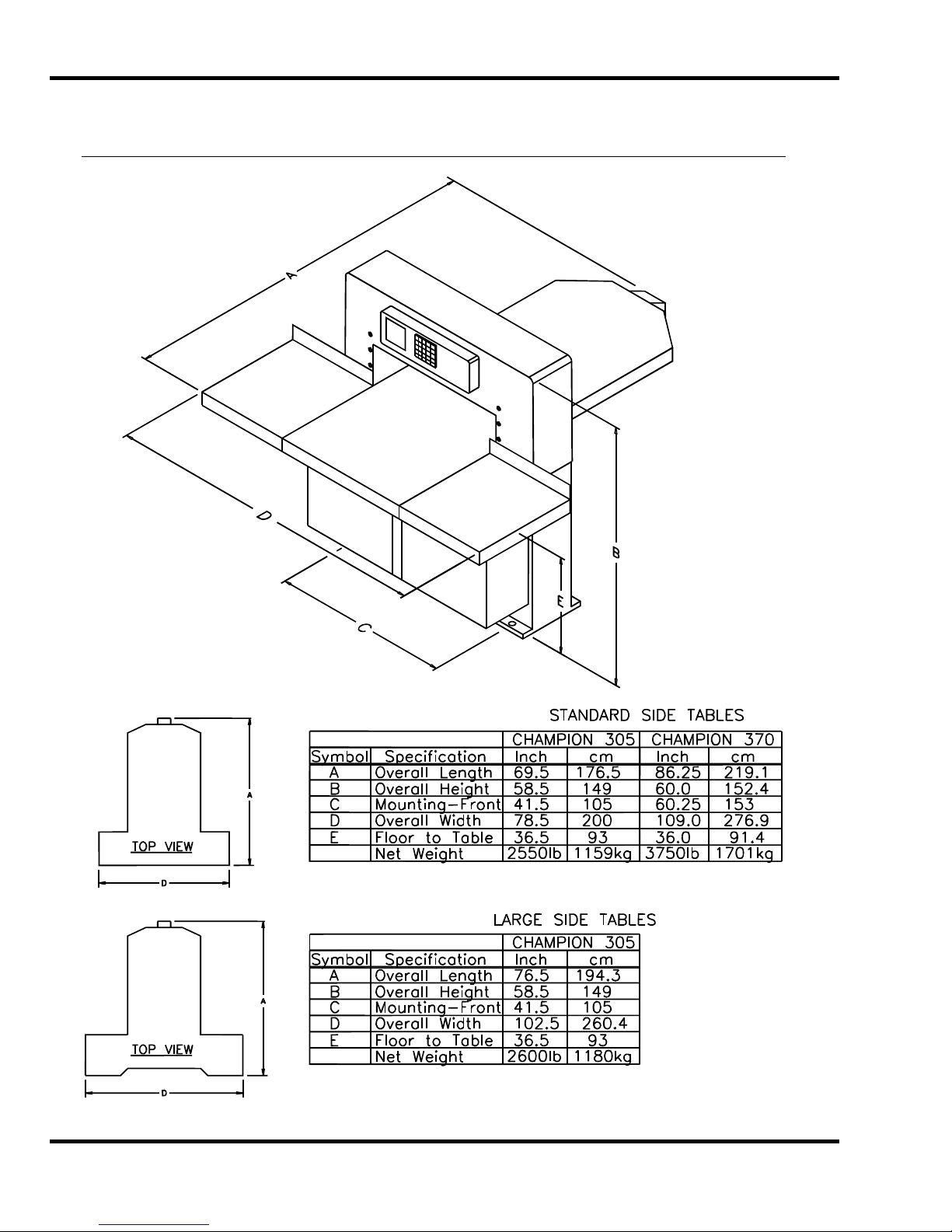
5.0 Footprint
5.0 Footprint
10
Page 11

6.0 Installation & Setup
6.0 Installation & Setup
6.1 Inspecting Shipment
This machine has been carefully packed to prevent damage during shipment. However, claims for
damage or loss are the responsibility of the recipient. Inspect all shipments as soon as they are
received. If there is any noticeable damage, note it on the freight bill. Visual and/or hidden damage
must be reported to the claims department of the carrier within 15 days. Contact your dealer if you
need any assistance. Check the contents of the box against the packing list on page 8. Make sure
there are no missing items.
6.2 Uncrating
This machine is lagged to a wood skid and covered with a triple-walled corrugated container. Loosen
the flaps of the carton where they are attached to the skid. When loose, the carton can be lifted
straight up. Remove the side tables and accessory box, which are also attached to the skid. Place
the cutter/skid about where the machine will be positioned and remove the lag screws from the skid.
6.3 Lifting/Moving Instructions
Unpacking, handling, and positioning should be done by professional riggers. If handling or
unpacking is a problem, your dealer or a local trucking facility should be able to supply or recommend
a qualified rigger. This 2550-lb/1157-kg machine should be moved with experienced peo ple and the
proper equipment. Do not risk personal injury or damage by attempting to move machinery with
inadequate equipment or manpower.
Lifting straps may also be used to lift the machine by placing the straps around the front and rear of
the table. When straps are used in this way, wood blocks must be placed beside the lead screw to
prevent damage, (Figure 2). A bent lead screw will cause the backgauge to bind.
Figure 2
The backgauge should be positioned all the way to the front of the table and straps placed as close
the machine body as possible. Gently lift the cutter, remove the skid and carefully place the cutter on
the floor.
Once the machine is off its skid, it can be moved with a forklift or pallet jack from the front. DO NOT
attempt to lift the machine from the sides or rear.
11
Page 12

6.0 Installation & Setup
6.4 Cleaning
Wipe down the table and bare metal surfaces with a non-flammable solvent such as CRC or blanket
wash. The table surface is cast iron, and it will rust if left unprotected. Coat the table with a nonabrasive wax. A Cutter Care Kit, p/n 16077, with cleaner and wax, is available through your
Authorized Challenge Dealer. The protective film on the console may be removed. Never clean
console with petroleum based solvents – damage will result.
6.5 Assembly
Unless otherwise specified, the only items that have been disassembled for shipping are the knife,
extension tables, and reach-around shields on the electric eyes. Knife installation instructions are
found in Section 8.0 Knife Installation/Changing. Extension table and reach-around shield attachment
instructions are as follows:
NOTE: Extension tables are heavy. Use two people to attach them to the machine.
1. Assemble the back plates to the extension tables. The extension table bolts and hex nuts are
packed in the tool kit box. Install the back plates such that the half-circle notch at the top of
the plates go toward the center of the cutter. These notches provide clearance for adjusting
the lower knife gib bolt.
2. One person should hold the extension table in position while the other aligns the holes and
starts threading the mounting bolts with washers. The mounting bolts are shipped installed in
the side of table- remove them to install tables.
3. Use a 9/16” socket and extension to snug tighten the mounting bolts, then tap the extension
table up or down with your hand or a rubber mallet until it is flush with the main table. Run a
straight edge or sheet of paper over the seam to check the fit. Make sure your stock will not
catch on the seam.
4. Insert the leveling setscrews into the threaded holes next to the mounting bolts. You may
have to loosen the mounting bolts slightly to allow enough play to level the table. After the
extension tables are leveled and the surface joints even, tighten the mounting bolts securely.
5. The extension tables are powder-coated and need only be wiped down with a dry cloth. DO
NOT apply solvents or abrasive cleaners to extension table surfaces. They may cause
discoloration or scratches.
NOTE: The reach-around shields for the electric eyes are in their shipping positions – follow the
instructions below to secure them in their operational position.
1. On the bottom of the electric eye housing, loosen (but do not remove) the screw furthest
back (closet to the machine frame) on each side.
2. On the bottom of the electric eye housing, loosen and remove the front two screws. Now
rotate each shield back and to the side – away from of the cut area. Line up the front holes
and re-install the front two screws. Tighten all screws (See the instruction sheet included in
the shipping material for more details).
ATTENTION
POTENTIAL CRUSH/LACERATION HAZZARD – THE SHIELDS ARE THERE FOR YOUR SAFETY.
: FAILURE TO INSTALL THE REACH-AROUND SHIELDS COULD CAUSE A
12
Page 13
6.0 Installation & Setup
6.6 Hydraulic Power Unit Removal
If installation requires that the machine pass through a doorway that is less than 49” but greater than
or equal to 42” wide, the machine should have been ordered from Challenge “knocked down” with the
table removed. If the machine must fit through a doorway that is less than 42” and greater than or
equal to 24-1/2”, the hydraulic power unit must be removed on-site. To remove the hydraulic power
unit, follow the instructions below.
1. Disconnect the electrical conduits to the hydraulic motor, air blower, and hydraulic cooling
fan, junction box.
2. Remove the filler cap and use a transfer pump to remove the hydraulic fluid into buckets.
3. Locate the hose that connects the manifold to the oil filter. Disconnect it from the filter.
Disconnect the hydraulic pump hose from the manifold. Attach the hose that was connected
to the manifold to the oil filter. Attach the hose that was connected to the filter to the
manifold. This will minimize oil leakage. After the unit is installed, reconnect the hoses to
their original location.
4. Remove the (4) bolts that attach the hydraulic assembly to the cutter base. They are located
at the bottom shelf the base.
5. USE EXTREME CAUTION WHILE REMOVING THE POWER UNIT. It is very heavy and
should be removed using a fork truck. CAUTION, the machine will be top heavy and may tip
easily with the power unit removed. Move the reservoir through the doorway on its side.
6. DO NOT ATTEMPT TO LIFT THE CUTTER BY PLACING STRAPS OR THE FORKS OF A
TRUCK UNDER THE CLAMP. This can damage the machine.
7. Reinstall the power unit, conduits, hoses, after the machine is in position. Refill the hydraulic
reservoir.
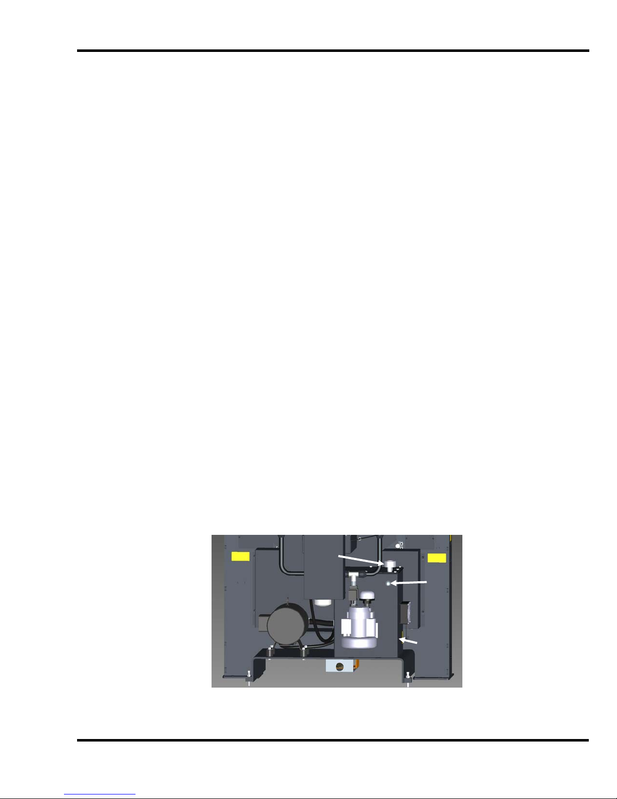
6.7 Hydraulic Check
The hydraulic reservoir is filled with 13-1/2 gallons of ISO VG 46 hydraulic oil at the factory. The fluid
level should be checked during installation, and at least once per week during normal operation. The
reservoir is located behind the cutter, beneath the table (Figure 3). The hydraulic tank has a sight
gauge in the rear for checking the oil level. The reservoir should be kept full at all times.
Filler
Cap
Sight
Gauge
Hydraulic
Tank
Figure 3
NOTE: DO NOT OVERFILL. Overfilling may cause leakage when the machine is hot.
13
Page 14

6.0 Installation & Setup
6.8 Power Hook-Up
For satisfactory operation, be sure that your cutter is wired for the correct phase and voltage and has
adequate power. The correct electrical specifications for your machine are shown on the serial plate.
Check the machine serial plate before connecting the power. For future reference, transfer this
information to the front cover of this manual.
Watch Setup Voltage- Inadequate power to the cutter can be a major source of problems. Too
many machines on the same circuit will reduce the power to each machine. Inadequate voltage will
cause overheating, loss of power, and in extreme cases, failure to operate. Test line voltage when
the shop is at actual working levels. Challenge recommends a dedicated line with a lockable
disconnect to provide adequate power for this machine.
CAUTION: SHOCK HAZARD! Always disconnect power at main
power panel before working on the cutter. Lock it out to prevent accidental power up. (See
Power Lockout Procedure page 5).
Important: You must have an adequate size circuit and heavy enough wiring for this machine. The
circuit size should be a minimum of 20% greater than the amperage rating on the machine
nameplate. If a wire is run over 75 feet (23 meters), the next size wire should be used. Check local
electrical codes.
Electrical Specifications for Champion Cutters
Volts Amps Phase Hz Circuit Size Wire Size Metric Wire
208/230V 25A 3 PH 60 Hz 40A #8 AWG 4mm sq.
460V 11.5A 3 PH 60 Hz 20A #12 AWG 10mm sq.
380/415V 10A 3 PH 50 Hz 20A #12 AWG 10mm sq.
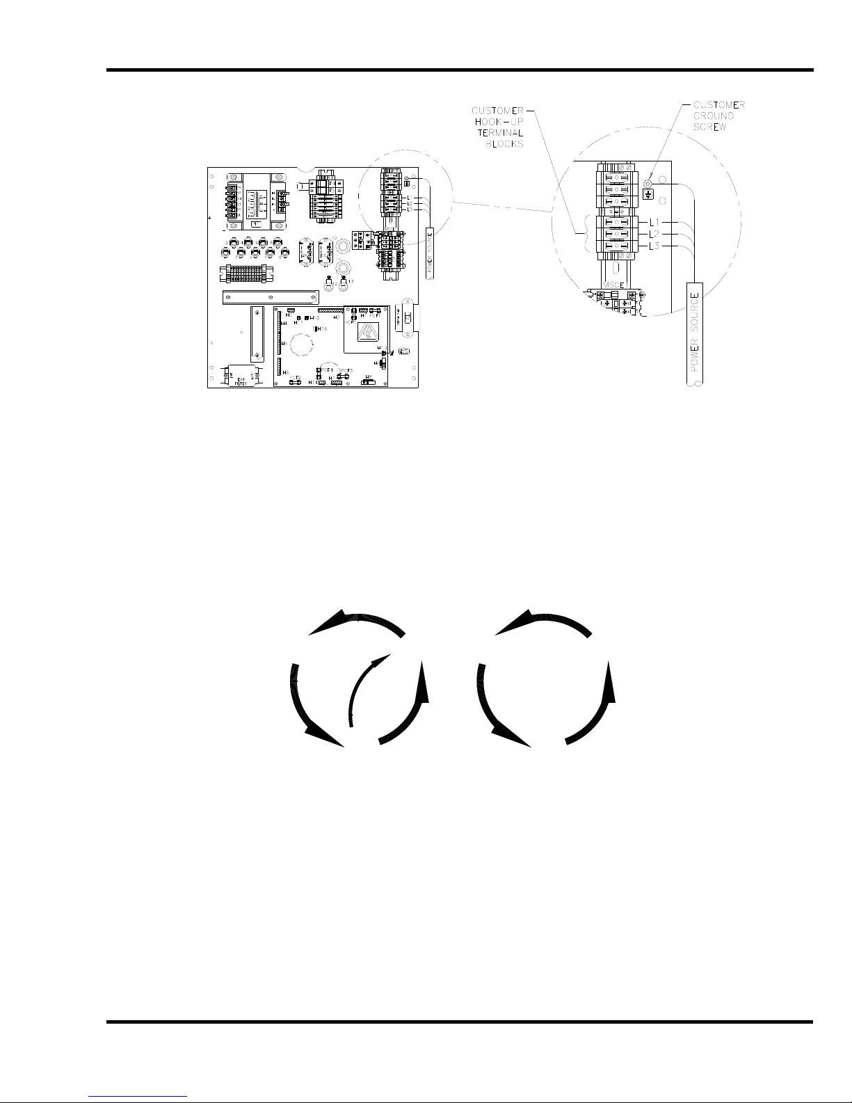
The power source is connected to the cutter through the bottom of the power panel (right hand side).
Hook-up procedure:
1. DISCONNECT AND LOCK OUT THE POWER at the main panel to prevent accidental powe r
up. (See Power Lockout, page 5).
2. Thread the power cord through a conduit connector into the power panel.
3. Fasten the ground lead to the ground terminal lug (Figure 4).
14
Page 15
6.0 Installation & Setup
Figure 4
4. Fasten the three power leads to the three terminals of the main power terminal block- L1, L2,
& L3.
5. Close the electrical panel doors and latch them. Unlock the main panel and turn on the
power. Turn on the main power disconnect switch located on the front face of the table.
6. Press both cut buttons simultaneously to activate the motor and check to make sure it is
turning the same direction as the arrow on the motor casing. If it is not turning the proper
direction, disconnect the power and exchange any two leads of the power cord as in Figure 5.
1
2
31 2
3
Figure 5
15
Page 16

7.0 Operation
7.0 Operation
IMPORTANT: DO NOT ATTEMPT TO OPERATE YOUR CUTTER UNTIL YOU HAVE
THOROUGHLY READ AND UNDERSTAND ALL OF THE INSTRUCTIONS FOUND IN THE
OPERATOR AND INSTRUCTION MANUALS INCLUDED WITH YOUR CUTTER. CALL YOUR
AUTHORIZED CHALLENGE DEALER IF YOU STILL HAVE ANY QUESTIONS.
Complete operating instructions for all TC Model paper cutters can be found in the TC Touch Screen
Control Operating Instructions manual that was included with your machine (Fig ure 6). If you do not
have a copy, or to download the latest version, visit: www.challengemachinery.com/support
.
Figure 6
7.1 False Clamp Plate
To prevent marking on pressure sensitive jobs, a false clamp plate has been included (installed) with
your machine. This plate attaches to the bottom of the clamp. It is secured from the front of the
cutter with three set screws.
ALWAYS disconnect the power and LOCK IT OUT before installing or
removing the false clamp plate. NEVER attempt to install or remove the false clamp plate while the
machine is running. Remove all tools and stand clear when recon necting power.
16
Page 17
7.0 Operation
To install:
1. DISCONNECT THE POWER AND LOCK IT OUT! (See Power Lockout, page 5.)
2. Position the false clamp plate under the clamp, (Figure 7). The locator pegs are positioned to
the rear of the cutter and are set into holes in the bottom of the clamp.
1/8” Allen
Wrench
Set
Screws
Locator
pegs
Figure 7
3. With a 1/8" Allen wrench, back off the setscrews in front of the clamp and raise the plate up to
the bottom of the clamp. It may be necessary to bring the clamp down onto a stack of paper
with the foot pedal in order to access the far left setscrew. Raise the false clamp plate evenly
or it will have a tendency to bind. When the plate has been raised into position and is flush
with the bottom of the clamp, tighten the setscrews to hold the plate in position.
4. Make sure that all tools have been taken off the cutter table, reconnect the power, and turn
on the machine.
NOTE: The backgauge will not move to a position less than 2" (51 mm) when the false clamp plate is
installed in the clamp.
When the false clamp plate is not in use, store it on top of the cutter, with the locator pegs inserted
into the 3 holes in the top cover. There is a sensor inside one of these holes that detects when the
false clamp plate is on top of the machine, thereby informing the machine that the false clamp plate is
not installed in the clamp. This allows the backgauge to be positioned less than 2” (51 mm), which it
will not do when the false clamp plate is installed in the clamp.
17
Page 18
8.0 Knife Installation/Changing
8.0 Knife Installation/Changing
Changing knives can be very dangerous unless safety precautions are
observed and extreme care is taken when handling knives.
• Make sure knife lifters are properly installed, see instructions following.
• Keep handling of unprotected knives to an absolute minimum.
• Clear off cutter table before removing knife.
• Have scabbard on cutter table and insert knife immediately.
• Warn people of any unprotected knife.
• Knife changing is a ONE PERSON OPERATION. Having more than one person trying to
change knives invites accidents.
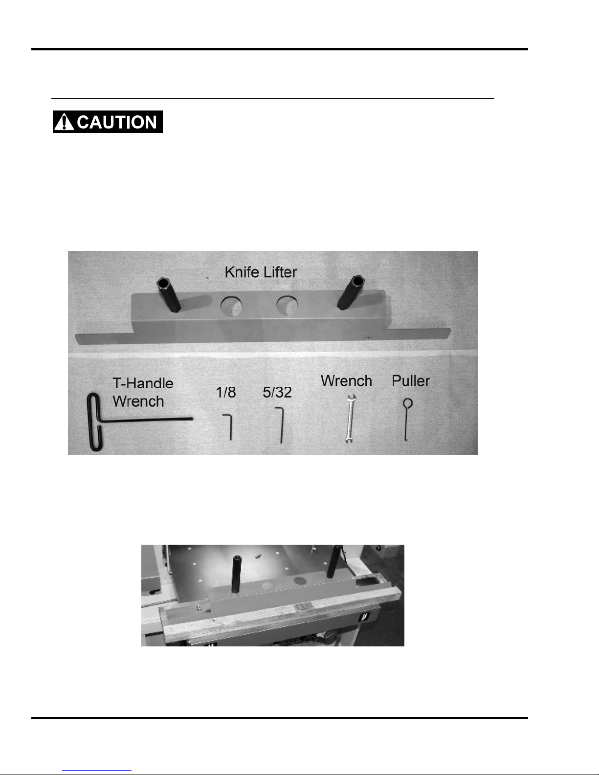
P/N: 47575
Figure 8 – Knife Changing Equipment
The knife changing equipment shown in Figure 8 is included in the cutter tool kit. The following
instructions show how to remove and install a new or re-sharpened knife. Read these instructions AT
LEAST ONCE before attempting to actually change or install any blades.
Figure 9
18
Page 19
8.0 Knife Installation/Changing
8.1 Knife Removal
1. Clear the cutter table. Place chipboard directly under the knife to prevent nicking if the blade
hits the table. On the TC touch screen menu choose “MAINTENANCE” and then “KNIFE
CHANGE”. Select “Knife Adjust Mode” then press and hold both cut buttons until the knife
and clamp reach the table. Now release the buttons (the knife and clamp should stay down ).
2. DISCONNECT THE POWER AND LOCK IT OUT, (See Power Lockout Procedure on pg. 5).
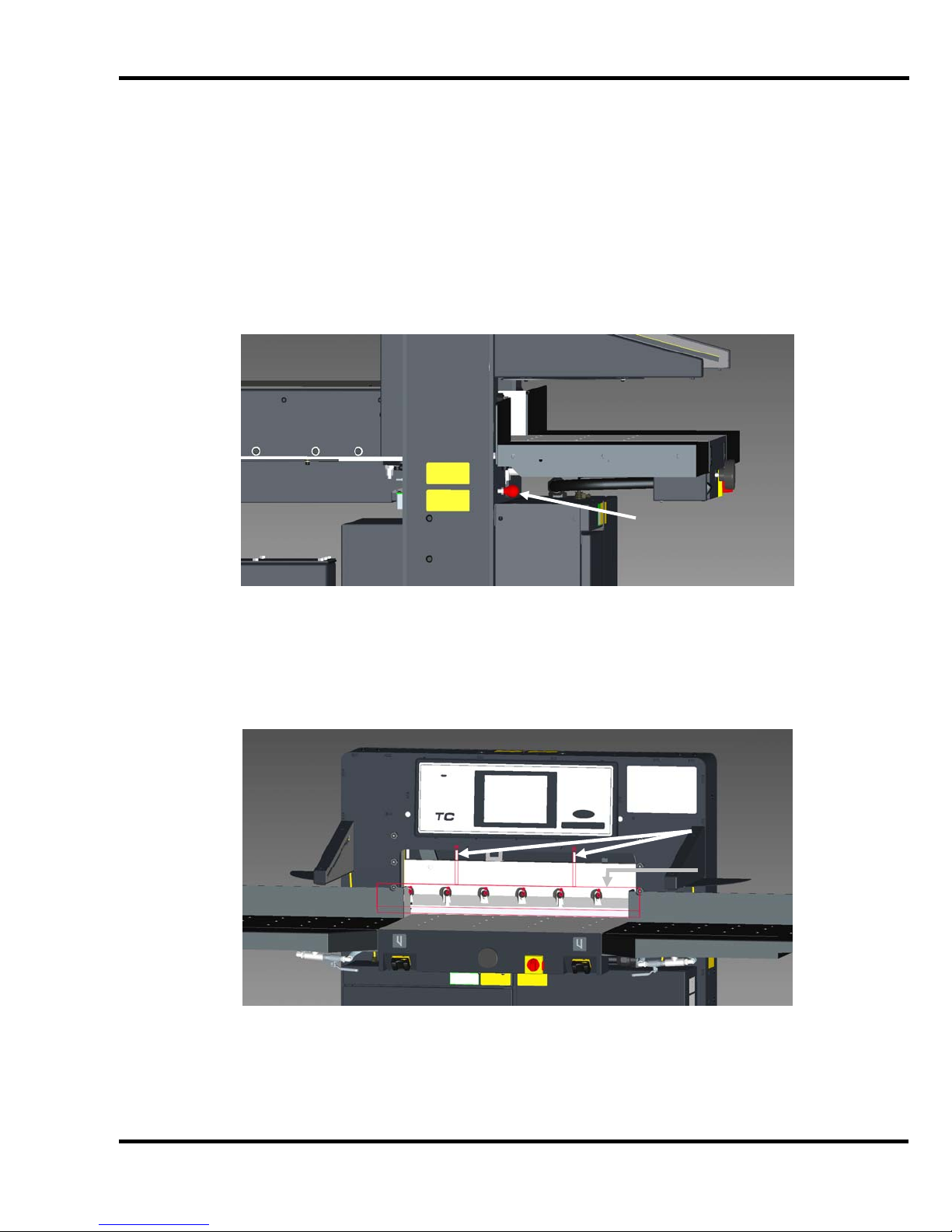
3. If equipped with the paper deflector option, lock it down by screwing the lock knob all the way
in (Figure 10).
Lock Knob
(Paper Deflector
Option Only)
Figure 10 – Paper Deflector Locking Knob
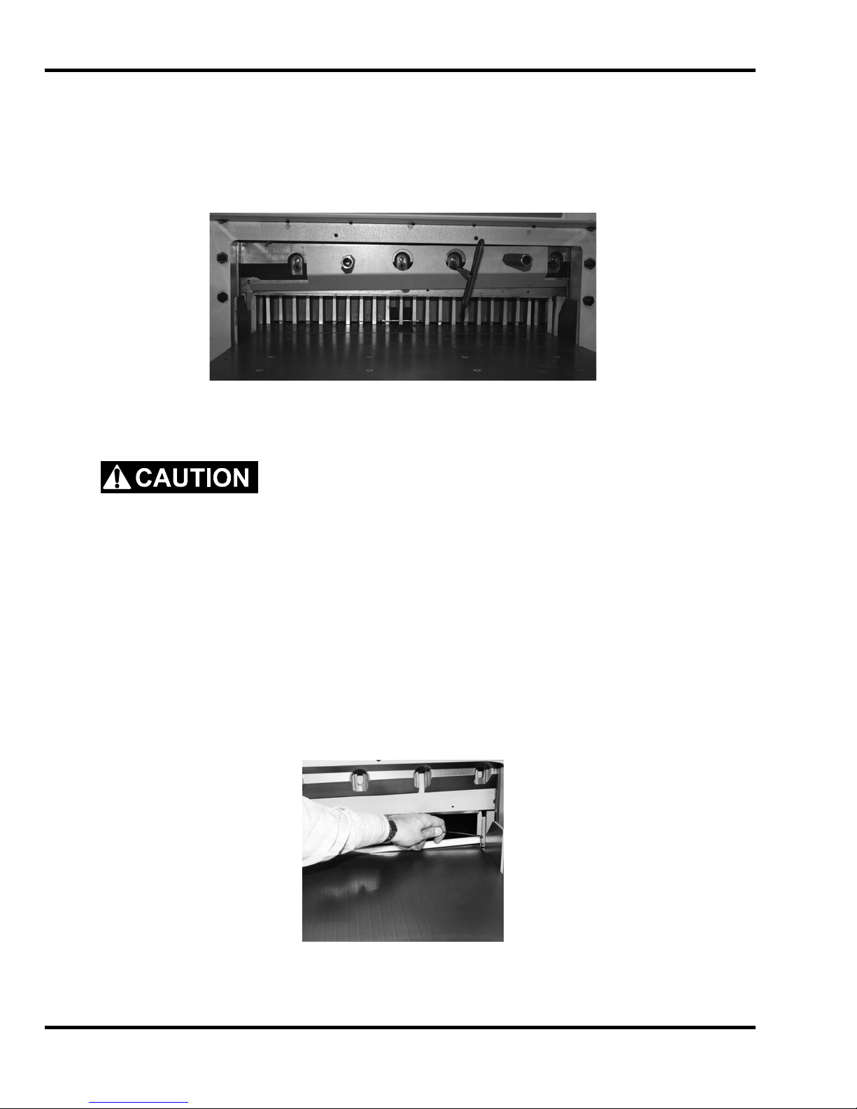
4. Back off the knife adjusting screws on the top of the knife bar, (Figure 11), as far as they will
go (counter-clockwise). A new knife will cut deeper than a knife that has been ground several
times. If the adjusters are not backed off, damage can result to the new knife and/or the
cutting stick.
Adjusting
Screws
Knife
5. Restore power to the machine and turn it ON. Follow the prompts on the screen to raise the
knife and clamp.
Figure 11 – Knife Adjusting Screws
19
Page 20
8.0 Knife Installation/Changing
6. DISCONNECT THE POWER AND LOCK IT OUT, (See Power Lockout Procedure on pg. 5).
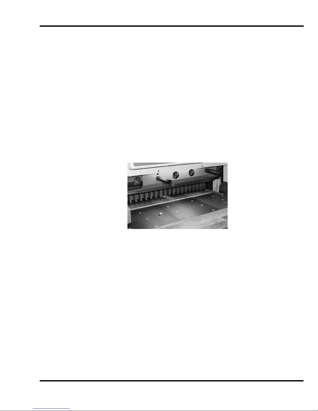
7. Remove the bolts in the two slotted holes of the knife bar and insert the knife lifter by
screwing in the two knife lifter handles. Tighten the handles enough to hold the blade in
place. Remove the remaining four bolts (Figure 12). The leftmost bolt must be removed
while the knife bar is “UP”.
Figure 12
8. Clear the table and put the empty knife scabbard on the table.
DANGER: Used knives are heavy and still very sharp. Be careful to
keep the edge away from your body and keep other people out of the area while handling the
blade. Severe lacerations and dismemberment could result from careless handling procedures.
9. Grasp the knife lifter handles firmly while turning counterclockwise to release the knife from
the knife bar. Slowly lower the knife down and to the right. Bring the left side out first.
10. Place the knife with attached lifter on top of the scabbard. Remove the lifter and slide the
knife into alignment with the scabbard screw holes. DO NOT FORGET TO INSTALL THE
SCABBARD SCREWS!
11. Send the dull knife to the grinder.
8.2 Knife Installation
1. Use the cutting stick puller, (Figure 13), to remove the cutting stick. Turn the cutting stick to a
new surface.
Figure 13
20
Page 21
8.0 Knife Installation/Changing
2. Check to make sure the paper deflector is locked down (Figure 10, page 19). Also check that
the knife adjusting screws have been backed out, (Figure 11, page 19).
3. Place the new knife scabbard on the cutter table.
4. Remove the knife retainer screws.
5. Place your fingers along the top edge of the scabbard and your thumbs in the holes in the
knife.
6. Pull the knife up in its scabbard until the bevel is exposed.
7. Place the lifter on top of the knife and insert the knife lifter handles into the corresponding
knife bolt holes (use the lowest holes) and thread the handles into the knife until they touch
the scabbard. Then back the handles off 1/2 turn.
8. Grasp the knife lifter handles, lift the blade, and insert the blade into the knife bar slot. Slowly
guide the blade into the cutter right end first, then bring the left end in parallel to the knife bar.
Raise the knife into the knife bar slot as high as it will go. Tighten the handles firmly to hold
the knife. An installed lifter is shown in Figure 14 below.
Figure 14
NOTE: If the blade will not go in, either the handles are screwed into the blade too far or the
blade is not centered over the table, and the end of the blade is hitting the end stop in the
knife bar.
9. Insert the rest of the knife bolts and washers, snug tighten them, but don’t tighten completely.
Be sure all bolts have washers. The correct washers are important for proper bolt
clearances!
10. Remove the knife lifter and insert the remaining two bolts and washers and snug tighten.
11. Place paper across the table to cover the cutting stick.
12. Restore power to the machine and turn it ON. Follow the prompts on the screen to preset the
backgauge. Then choose “MAINTENANCE” and then “KNIFE CHANGE”. Select “Knife
Adjust Mode” then press and hold both cut buttons until the knife and clamp reach the table.
Now release the buttons (the knife and clamp should stay down).
13. DISCONNECT THE POWER AND LOCK IT OUT, (See Power Lockout Procedure on pg. 5).
14. Turn the knife adjusters down (Figure 11, page 19) a little at a time, until the blade cuts
through the paper evenly over the entire length of the stick. Be sure the blade is parallel to
21
Page 22

8.0 Knife Installation/Changing
the cutting stick, or one end may cut deeper than the other, causing uneven wear on the
stick.
15. Tighten all the bolts and release the paper deflector.
16. Restore power to the machine and turn it ON. Follow the prompts on the screen to raise the
knife and clamp, and then to preset the backgauge.
17. Make a test cut through a full lift of stock. Make minor adjustments by loosening the bolts
and repeating steps 9 through 11.
NOTE: If the knife ends cut but the middle does not, you could have dips or uneven spots in either
the knife or the cutting stick. These can be eliminated to some extent by laying 1/2" (13mm) strips of
paper beneath the cutting stick to shim it up.
8.3 Knife Care Tips
! KNIFE SAFETY ! Knives are DANGEROUS!!! They are heavy and
very sharp, even after use. Keep the edge away from your body and keep the area clear of
others when handling knives. Never touch the cutting edge! To prevent personal injury and
damage to the knife, always keep knives in their holders with screws tightened. You are
aware of the dangers, but others may not be. Never attempt to hone, polish, or service the
knife in any way. Failure to follow safety procedures may result in severe lacerations or
dismemberment.
8.3.1 Knife Blade Life
Knife blade life, or the time between sharpenings, can be affected by many factors. One important
factor is the type of paper being cut. Abrasive paper, such as recycled paper, soft paper such as
newsprint paper, and bound books can all significantly shorten knife blade life. Also, if the knife depth
is set too deep, the knife will cut too deep into the cutting stick and can dull the knife blade.
A knife can last between 2,000 and 5,000 cuts before it needs to be sharpened. Cutting soft paper
(such as newsprint paper) or paper with high post-consumer recycled content ca n cause the knife to
need sharpening after only 2,000 to 3,000 cuts. Cutting pure paper, such as bond pape r with no
recycled content, or hard paper can allow the knife to be used for as many as 5,000 cuts before it
needs to be sharpened. In all cases, the operator should continually check the quality of the cut to
determine when the knife blade needs to be sharpened. Some characteristics that indicate a blade
needs sharpening are:
• The knife hesitates or stalls while making a cut.
• The sheets are not all cut to the same length (usually the top few sheets are longer than the
rest of the sheets - this is sometimes called “draw”).
• Cut marks appear on the cut face of the paper.
• The profile of the cut (side view) is not perpendicular to the table.
• The cut does not appear straight when viewed from the top.
• The knife makes a “rougher” sound as it passes through paper.
• Nicks are visible on the cutting edge of the knife.
22
Page 23

8.0 Knife Installation/Changing
8.3.2 Cutting Stick
A worn cutting stick can affect the cut quality of the bottom sheets. When this happens, the cut stick
can be rotated. Usually, the stick should be rotated one or two times between knife sharpenings.
There are 8 possible cut stick positions. The stick can be rotated 4 times, and then turned en d to
end, and rotated 4 times again.
8.3.3 Bevel Angle
Challenge recommends that bevel angles for the Champion 305 knives be in the range of 21° to 23°.
In general, a 21° bevel angle will provide better cut quality when cutting soft paper (such as
newsprint), recycled paper, or bound books. However, 21° angle knives can become dull sooner than
23° knives, which results in shorter knife blade life. A knife with a 23° bevel angle, on the other hand,
will not dull as easily, and can provide satisfactory results when cutting most types of paper. Knives
shipped with the Champion 305 from the factory have a bevel angle of 23°.
8.3.4 Helpful Suggestions
If your establishment is large enough to purchase more than one set of knives, have one set
beveled at 21° and the other at 23°. Note: A set consists of 3 knives: one in the machine,
one as a back up, and one at the grinder.
If the machine seems to strain but the cut quality is still good, reduce the pile height. You
may also carefully apply glycerin to the bevel when cutting hard, coated paper. Tie a cloth to
the end of a stick; dip the stick in glycerin, and apply. Never apply by hand! In lieu of
glycerin you may lightly rub white bar soap along the bevel. Lubrication will prolong the life of
your machine and reduce maintenance.
8.3.5 Knife Care
• To prevent corrosion, knives are coated with light oil. It should be REMOVED WITH CARE.
• While removing or installing a knife, be careful not to allow the edge to bump against the
machine. Nicks will result.
• If a knife bolt is damaged, replace it.
• Always keep knife bolts securely tightened.
• Always use the heavy-duty knife bolt washers provided by Challenge. Failure to do so could
result in scratching or marring of the clamp face.
• Store knives in a dry environment to prevent corrosion.
• Never attempt to service a knife in any way.
23
Page 24

8.0 Knife Installation/Changing
NOTES
24
Page 25

8.0 Knife Installation/Changing
Maintenance Section
NOTICE
The instructions on the following
pages are for the use of trained
service personnel only!
Attempting to perform repair and
replacement procedures without
proper training may cause
machine damage or operator
injury!
PARTS CUSTOMERS: Parts with the express understanding that they are to replace parts
found missing or no longer serviceable on equipment designed and/or manufactured at
Challenge. The Challenge Machinery Company assumes no liability for any modification or
alteration to any Challenge products, and any such modification or alteration to any
Challenge product is not authorized by The Challenge Machinery Company. Any
modification or alteration of any Challenge product will void any remaining warranty.
25
Page 26

9.0 Cleaning
9.0 Cleaning
9.1 Table
The table of a paper cutter requires periodic maintenance to remove surface oxidation. Polishing is
also required to provide a smooth surface for paper to move freely. The frequency of this
maintenance will be determined by a number of factors. Among these are the humidity,
environmental dust, handprints, liquid spills, and type of paper stock. We recommend the use of the
Challenge Cutter Care Kit P/N 16077 for of your table care needs.
To prepare a new machine’s table, follow the procedure below:
1. Remove the rust-protective coating from the table with a solvent.
2. Remove all solvent residue from the table with a dry cloth. Continue until the cloth shows no
sign of residue.
3. Apply a light coating of an SAE 10-weight non-detergent motor oil or equivalent to the table
and allow it to penetrate for at least one hour.
4. Remove all excess oil from the table with paper toweling (not cloth) until the paper towel you
are using shows no sign of oil.
5. Apply a paste wax (Challenge P/N 16078) to the table to seal the pores of the metal.
Note: Do not use a wax that contains a cleaning compound on the table. The cleaner contains
microscopic abrasive particles that will cause wear between the table and the bottom of the
backgauge. A silicone spray (Challenge P/N 16079) will show the same type of wear as the
cleaner if the excess silicone is not removed. If the excess is not removed, the silicone spray has
a substance that holds the silicone to the surface it is sprayed on that causes a black, gummy
build-up under the backgauge. If a silicone spray is used, paper toweling must be used to
remove the excess to prevent this wear and build-up.
To clean surface oxidation from a table, follow the procedure below:
1. Spray “Rust-B-Gone” (Challenge P/N 16080) on the table and allow it to dissolve the rust.
Then remove it with paper toweling. Or, pour a small quantity of SAE 10-weight motor oil
onto the table. Using a Scotch-Brite Pad or a 400 grit sand paper, polish the table following
the “grain” of the metal until all oxidation is removed to your satisfaction.
2. Remove all of the oil from the table until the cloth you are using shows no sign of residue.
3. Apply a light coating of an SAE 10-weight non-detergent motor oil or equivalent to the table
and allow it to penetrate for at least one hour.
4. Remove all excess oil from the table with paper toweling (not cloth) until the paper towel you
are using shows no sign of oil.
5. Apply a paste wax (Challenge P/N 16078) to the table to seal the pores of the metal.
Note: Do not use a wax that contains a cleaning compound on the table. The cleaner contains
microscopic abrasive particles that will cause wear between the table and the bottom of the
backgauge. A silicone spray (Challenge P/N 16079) will show the same type of wear as the
26
Page 27

9.0 Cleaning
cleaner if the excess silicone is not removed. If the excess is not removed, the silicone spray has
a substance that holds the silicone to the surface it is sprayed on that causes a black, gummy
build-up under the backgauge. If a silicone spray is used, paper toweling must be used to
remove the excess to prevent this wear and build-up.
9.2 Console
The console should be cleaned with a mild water based detergent applied to a damp cloth or
paper towel. Petroleum based solvents will damage the console.
9.3 Machine Frame
1. The machine frame should be cleaned with a mild, water based detergent applied to a damp
cloth.
2. Always be careful when cleaning around safety warning labels. Use limited am ounts of
cleaners in those areas.
27
Page 28
10.0 Lubrication
10.0 Lubrication
A clean, lubricated machine will cut more accurately, run longer, with less downtime, and fewer
repairs.
Schedule lubrication maintenance both early in the day and early in the week. This allows the
lubricants to work into the machine. Lubrication at the end of the day or week allows the lubricants to
run off without any benefit to the machine.
Clean off dirty, excess grease. Clean accumulated dust off valves, hoses, and connections. Dust
build-up increases operating temperatures and causes premature wear of all hydraulic component s.
Oil and grease WEEKLY as described below.
When necessary, send the knife down by choosing “MAINTENANCE” and then “KNIFE CHANGE” on
the TC touch screen. Select “Knife Adjust Mode” then press and hold both cut buttons until the knife
and clamp reach the table. Now release the buttons (the knife and clamp should stay down).
DISCONNECT THE POWER AND LOCK IT OUT, (See Power Lockout Procedure on pg. 5).
Most moving parts require lubrication. Remove all panel covers and look for all oil locations (marked
with red paint). Make sure oil holes are not plugged and lubricate with a 30 weight oil. See the
photos below for critical locations (not all locations are illustrated here). Notice that some are oil
locations and some are grease points. Wipe off old and excess grease. Use a National Lubricating
Grease Institute No. 1 consistency, extreme pressure grease.
Replace all guards before operating. Never operate cutter with any
guards removed.
GREASE OIL
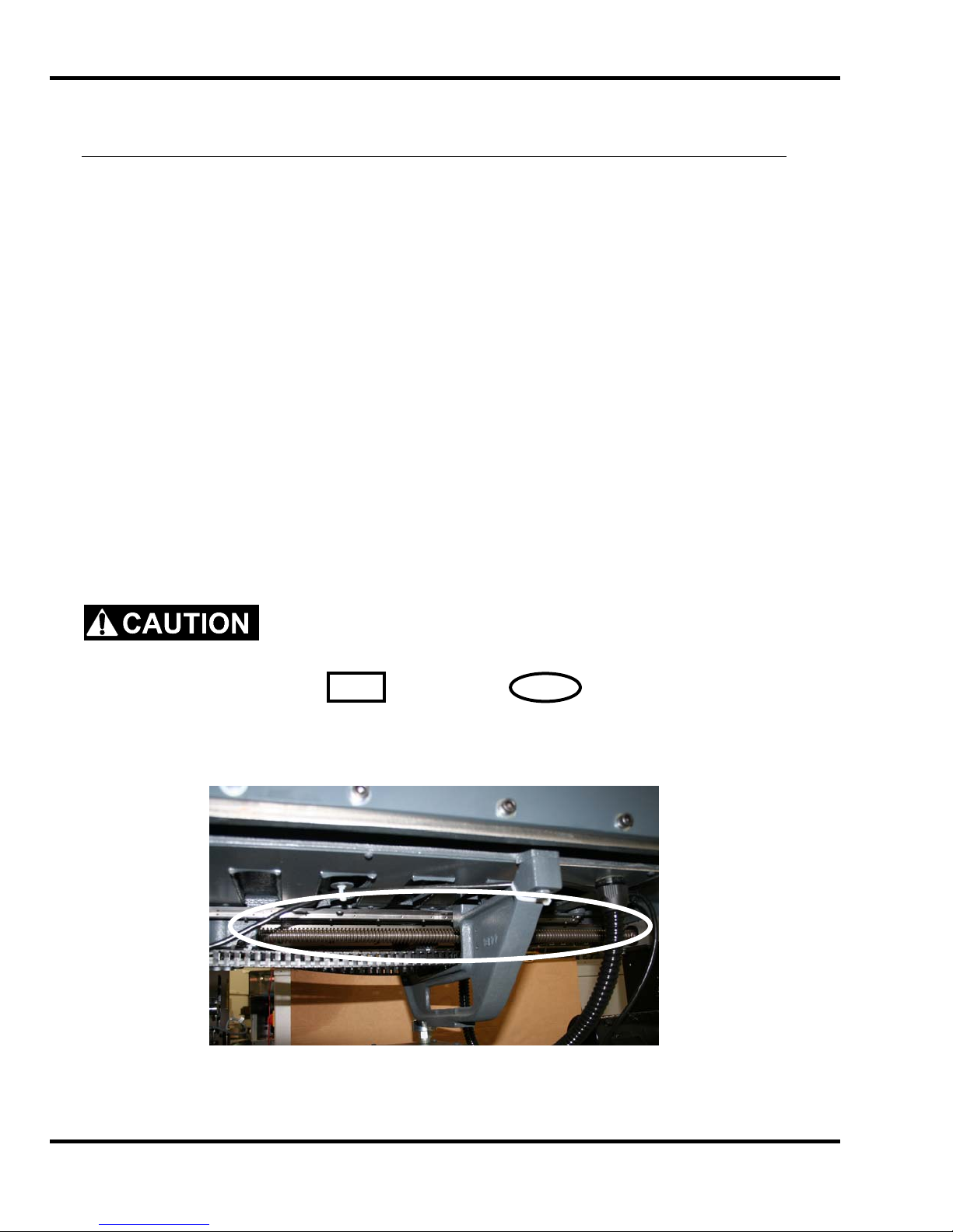
Backgauge leadscrew (oil):
Figure 15
28
Page 29
10.0 Lubrication
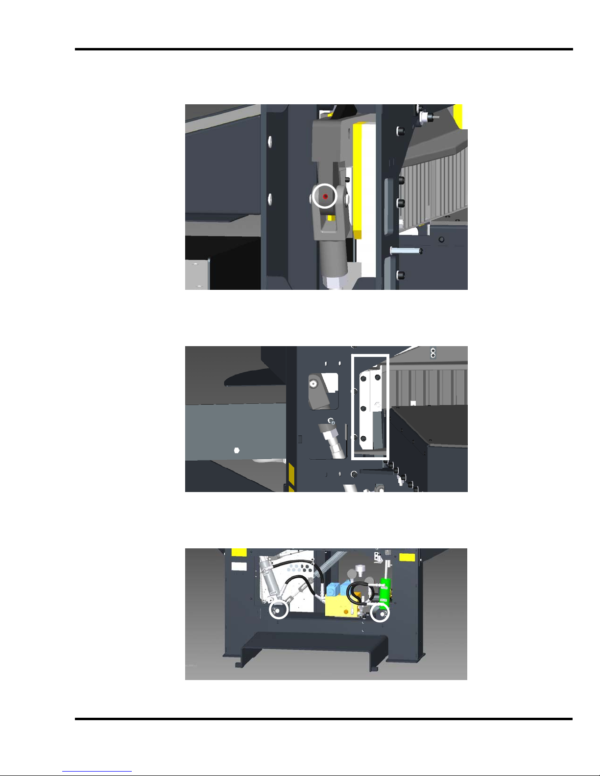
Knife bar pull-down pin (oil):
Figure 16
Left and right clamp guides (grease):
Lower knife and clamp cylinder pins (oil):
Figure 17
Figure 18
29
Page 30
10.0 Lubrication
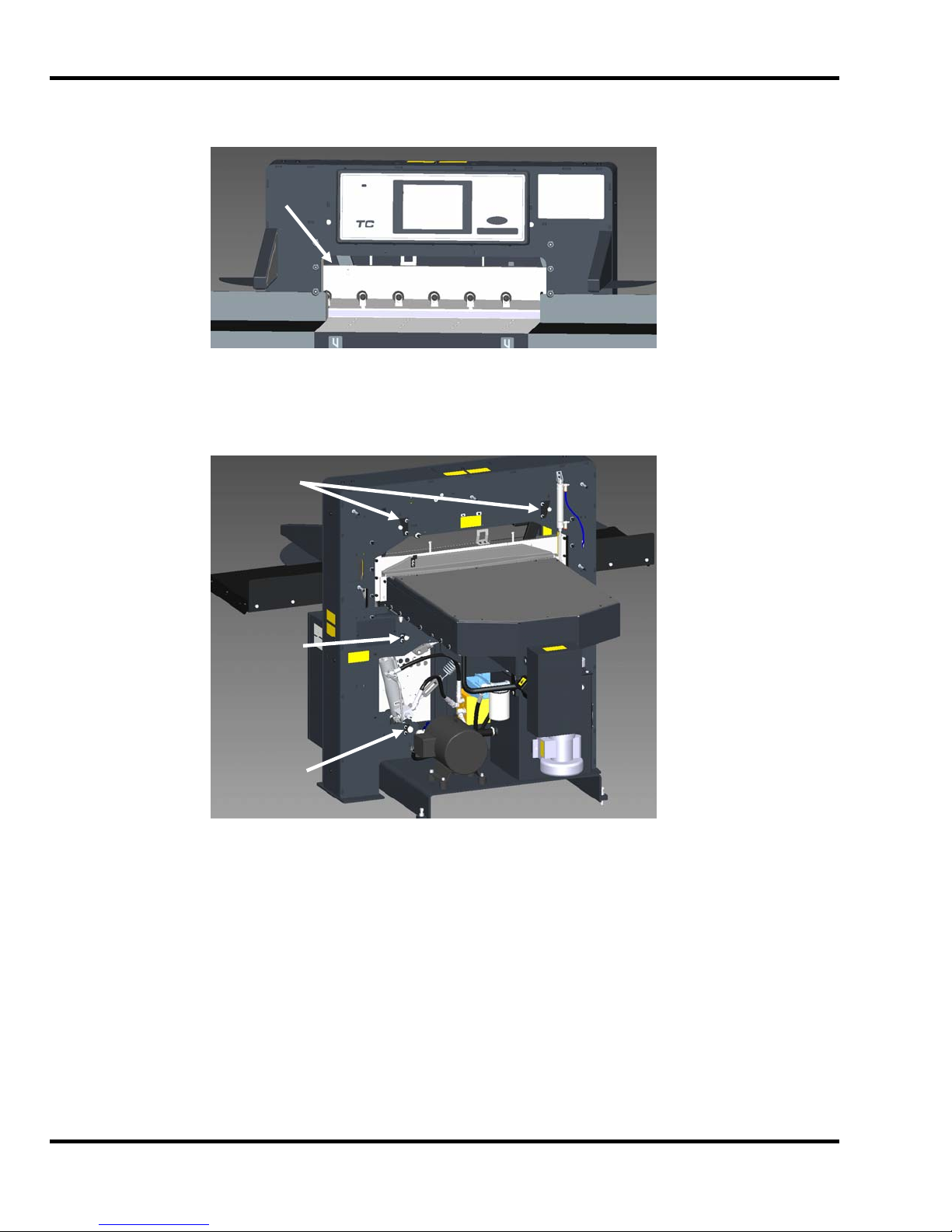
Wipe down the knife bar to remove dust and debris (Figure 19).
Knife Bar
Figure 19
Check knife bar link, bell crank, and hydraulic cylinder pin keepers to make sure they are in pla ce an d
secure (Figure 20).
Knife Bar
Link Pin
Keepers
(x2)
Bell Crank
Pin Keepers
(x2)
Hyd. Cyl.
Pin Keepers
(x2)
Figure 20
30
Page 31

11.0 Hydraulic System
11.0 Hydraulic System
The Champion Series Cutters have both hydraulic cutting and hydraulic clamping operation. The
cutter is powered by an electric motor coupled directly to a hydraulic pump. The pump has a fixed
flow rate output of 5 GPM at 1,800 psi (max. system relief setting) at 1,800 RPM.
The clamp action is powered by a hydraulic cylinder. When the cut buttons are depressed, this
cylinder pulls on the clamp bell crank and brings the clamp down (or brings the clamp up to full
hydraulic pressure if the manual foot clamp is down). The cutting action is also powered by a
hydraulic cylinder connected directly to the knife bar. The knife sequence valve generates 1,600 PSI
of back pressure throughout the system to maintain full clamp pressure during the cut. One
advantage of the hydraulics is the immediate return of the knife when the cut buttons are released.
The hydraulic fluid should be changed YEARLY or EVERY 1,000 HOURS of operation.
The oil filter (Challenge part H-227-1) should be changed YEARLY or whenever any repairs are
made to the hydraulic system.
NOTE: Failure to change the oil and filter when needed can damage the seals i n the clamp and knife
cylinders.
Check the level of the hydraulic reservoir WEEKLY or whenever the machine sounds like it is
laboring (this could be due to low oil level). The tank has a sight gauge on the back so you can check
the oil level.
The hydraulic tank, fan, manifold, and fittings should be wiped off WEEKLY to maintain maximum
cooling of the tank/hydraulic oil.
11.1 Recommended Hydraulic Oil
Use only ISO (International Standards Organization) Viscosity Grade 46, rust, oxidation, and foam
inhibiting, non-detergent hydraulic oil. Oils other than the recommended type will cause seals,
cups, and O-rings to deteriorate. The proper hydraulic oil can be purchased in 5 gallon containers
from your authorized Challenge Dealer using the Challenge part number: S-1991-3.
NEVER USE Automatic transmission oil or brake fluid as a substitute!
Oils other than the recommended type will cause seals, cups, and O-rings to deteriorate.
Unsafe operations conditions will result.
11.2 Changing the Oil
Only change oil when it is cold. Burns could result from changing hot oil.
Before beginning, you will need (3) empty five gallon buckets, three oil pans or more, a funnel and an
assistant. If oil is hot, wait until it cools.
1. Make sure main power to the machine is off.
2. Remove the reservoir tank cover (Figure 21).
31
Page 32

11.0 Hydraulic System
Reservoir
Tank Cover
Figure 21
3. Using a hand drill and transfer pump commonly found at hardware and home improvement
stores, transfer the used oil to empty containers.
4. Remove the magnet stuck to the bottom of the tank. Clean off any debris that may be
attached to it.
5. With a clean rag, wipe out any visible debris remaining in the tank.
6. Place the magnet at the location from which it was removed.
7. Replace the oil filter. Place a thin film of new hydraulic oil on the seal of the new filter to
insure a proper seal. Firmly hand-tighten the filter onto the filter head.
8. Using the transfer pump, fill the tank with 13.5 gallons of the recommended fluid (See Section
11.1 - Recommended Hydraulic Oil) until the level is just above the sight gauge shown in
Figure 21.
9. Re-install the tank cover with gasket.
10. Before turning on the machine, make sure all hydraulic hose fittings are tight.
11. Turn on main power to the machine. Turn on the hydraulic motor by pressing both cut buttons
once. Inspect the hydraulic system for leaks. If leaks are found, turn off main power to the
machine and tighten any leaking fittings.
11.3 Hydraulic Valve Adjustments
Sight
Gauge
Hydraulic
Tank
Several of the following tests require the machine to be operational for
checking and adjusting. Be very careful that tools and other people are clear of moving parts and that
the cutter is not accidentally operated while adjustments are being made. Disconnect the power and
lock it out, (see Safety Precautions, page 5) whenever working on the machine unless the directions
specifically require the machine to be powered.
NOTE: Pressure settings fluctuate with oil temperature. Set pressures when the oil is hot.
32
Page 33

11.0 Hydraulic System
For initial setup, adjust in the following order:
1. Main System Relief Valve (Figure 22) – 1,800 psi
2. Knife Down Sequence Valve (Figure 23) – 1,600 psi
3. Clamp Up Sequence Valve (Figure 22) – 400-600 psi
4. Clamp Pressure (TC Console) – 400min/1,400max psi
Clamp
Pressure
Gauge
Main
System
Gauge
Main System
Relief Valve
Electronic
Clamp Valve
Sequence Valve
Figure 22
Knife Down
Sequence
Valve
Figure 23
1. Main System Relief Valve (Figure 22) – 1,800 psi
This valve maintains the overall hydraulic pressure for the entire system. Factory setting:
1,800 psi.
To Check:
a. Open the left access door on front of the cutter.
Clamp Up
33
Page 34

11.0 Hydraulic System
b. Turn the power on and make a cut to hold the knife down on the cutting stick. Read the
pressure on the main system pressure gauge (front gauge) while the knife is down. If the
gauge does not read 1,800 psi, an adjustment is needed. In order to have more time to
read the gauge, it may be helpful to send the knife down using the “Knife Change” feature
found in the Maintenance pull-down menu.
To Adjust:
a. Loosen the lock nut on the relief valve. Use an Allen wrench to turn the adjusting screw.
Turn clockwise to increase pressure, counter-clockwise, to decrease pressure.
b. Make a cut and hold the buttons in. Or send the knife down using the “Knife Change”
feature found in the Maintenance pull-down menu. Adjust the valve screw until you have
the correct pressure.
c. Tighten the lock nut while holding the hex wrench in place.
2. Knife Down Sequence Valve (Figure 23) – 1,600 psi
This valve controls the clamp and knife sequence. It keeps the knife up until after the clamp
has made contact. It is located near the lower port of the knife cylinder. Factory Setting:
1600 psi.
NOTE: Main System Pressure must be set at 1,800 psi before making this adjustment.
To Check:
a. Open the left access door on front of the cutter.
b. Press the cut buttons while reading the pressure on the main system pressure gauge
(front gauge). The gauge should read approximately 1,600 psi as the knife is moving
down (when bottomed, the gauge will jump to 1,800 psi showing the Main System
Relief Pressure previously set).
To adjust:
a. Remove the lower rear cover.
b. Loosen the lock nut. Note: This lock nut also serves as a seal. Some hydraulic fluid
may leak out while it is loose.
c. Make a cut and hold the buttons in. While reading the main system gauge, adjust the
valve until you have the correct pressure. Clockwise to increase, counter-clockwise to
decrease.
d. Tighten the lock nut while holding the hex wrench in place.
3. Clamp Up Sequence Valve (Figure 22) – 400-600 psi
This valve maintains clamp pressure so the clamp remains down until the knife has stopped
in the up position. Factory setting: 400-600 psi.
To Check:
a. Open the left access door of the cutter.
34
Page 35

11.0 Hydraulic System
b. Press the cut buttons, and while reading the pressure on the main gauge (front
gauge), release them. The gauge should read between 400-600 psi as the clamp is
going up. There should be no clamp movement until the knife is stopped in the up
position.
To Adjust:
a. Remove the protective cap and loosen the lock nut on the clamp up sequence valve.
b. Make a cut, then release the buttons. Read the main gauge as the clamp is
returning. Adjust the valve for a reading of 400-600 psi.
c. Tighten the lock nut while holding the hex wrench in place and replace the protective
cap.
4. Electronic Clamp Pressure Setting (TC Console) – 400min/1,400max psi
The electronic clamping control allows the convenience of changing the clamp pressure at
the control console, as well as the ability to program different clamp pressure settings within
programmed jobs. The clamp pressure is controlled by use of a slide bar on the TC touch
screen located at the lower left corner of the screen. A number between 0 and 15 will be
displayed, indicating the current pressure setting (0 being the lowest, 15 the highest). To
adjust the actual clamp pressures at the minimum (0) and maximum (15) settings, follow the
procedure below:
Adjustment of the Electronic Valve:
a. On the TC touch screen, select the Maintenance pull-down menu then choose Setup.
Then select the Service Info tab, and in the box for Enable Tabs Code, enter 6125.
Now select the Hydraulic Settings tab. The screen should look similar to Figure 24
below:
Figure 24
35
Page 36

11.0 Hydraulic System
b. To set the maximum pressure, first make sure the correct slide bar is “active” by
touching the appropriate slider button. Now press both cut buttons, and after the
clamp has contacted the table and while the knife bar is coming down, read the
pressure on the right hand pressure gauge. It should be set at 1,400 psi. If not,
adjust the maximum clamp pressure slider button higher or lower and re-check the
clamp pressure reading on the gauge. Repeat until the pressure is properly set at
1,400 psi.
c. To set the minimum pressure, first make sure the correct slide bar is “active” by
touching the appropriate slider button. Now press both cut buttons, and after the
clamp has contacted the table and while the knife bar is coming down, read the
pressure on the right hand pressure gauge. It should be set at 400 psi. If not, adjust
the minimum clamp pressure slider button higher or lower and re-check the clamp
pressure reading on the gauge. Repeat until the pressure is properly set at 400 psi.
d. To adjust the directional valve shift delay, first make sure the correct slide bar is
“active” by touching the appropriate slider button. Start with the slider button
somewhere near the middle. Make a cut and watch the motion of the knife bar. If the
knife bar hesitates at the bottom of its stroke, decrease the delay by moving the slider
button to the left. If you hear an unusual “clunk” sound when the knife reaches the
bottom of its stroke, increase the delay by moving the slider button to the right.
e. The knife cushion value is applicable to Titan 265 cutters only. Changing this setting
on Champion 305 cutters has no effect.
f. When finished, press Save and Exit.
36
Page 37

12.0 Adjustments
12.0 Adjustments
Several of the following tests require the machine to be operational
for checking and adjusting. Be very careful that tools and other people are clear of moving
parts and that the cutter is not accidentally operated while adjustments are being made.
Whenever working on the machine, disconnect the power and lock it out (see SAFETY
PRECAUTIONS, page 5) unless the directions specifically require the machine to be powered.
12.1 Electric Eye Alignment
If the electric eyes are not in alignment, or if they become out of alignment during a cut cycle due to
vibration, the machine will see them as blocked and will cease any downward motion.
To check if the electric eyes are aligned properly, turn on the power switch and look at the indicator
light pattern on the receiver (left hand unit). If the eyes are functioning properly and aligned properly,
and if there are no obstructions, the light pattern will look like the one shown in Figure 25 below.
Power
Status
(Green = OK)
(Red = Problem)
Figure 25 – Electric Eye Indicator Lights
To simulate the vibration caused by a normal cut cycle, gently tap on the electric eye housings one at
a time with your hand. Watch the indicator lights to see if any of them change.
If the status light or any of the zone indicator lights are red, this indicates an obstruction. However if
there are no physical obstructions blocking the eye beams, then most likely the electric eyes a r e out
of alignment. To adjust:
1. Remove the inner housing covers from both eye housings.
2. Loosen the outer mounting screws (Figure 26) to adjust the eye beam units until they are
aligned over their length.
Diagnostic
Zone Indicators
(Green = Clear/Aligned)
(Red = Blocked/Misaligned)
37
Page 38

12.0 Adjustments
Outer
Mounting
Screws
Inner Mounting
Figure 26
3. Loosen the inner mounting screws (Figure 26) to rotate the beams until they are aligned over
their width. When the indicator lights indicate proper alignment as shown in Figure 25,
tighten all screws.
4. Replace the inner housing covers and re-check the alignment as indicated above.
Screws
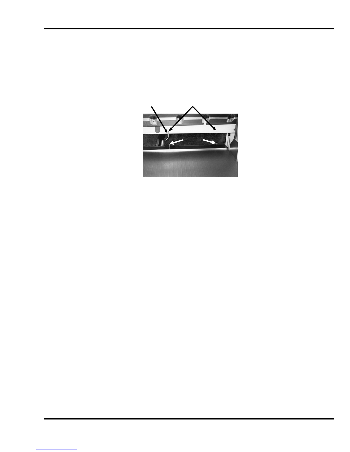
12.2 Backgauge Gib Adjustment
If the backgauge does not stay squared or jumps up and down when jogging paper against it, the
backgauge gib screws are probably loose or worn. Position the backgauge approximately 2” (5055mm) from the rear of the table and turn off power.
Remove the rear table cover. From the back, hold each end of the backgauge and try pulling one
end while pushing the other to rock it side to side. If there is noticeable side-to-side play in the
backgauge, the gibs will need adjusting. Check for play at various positions on the table, (Figure 27).
Note: there will be some front to rear movement between the backgauge nut and screw.
Figure 27
The backgauge has two gibs that ride on an iron rail underneath the table, (Figure 28). These are
adjusted with setscrews, which are held in position with jam nuts.
38
Page 39

12.0 Adjustments
Set Screws
& Jam Nuts
Rail
Figure 28
To adjust:
1. Run the backgauge back to 28” (711mm) and disconnect the power.
2. Always adjust the side gib first. Loosen all jam nuts and adjusting screws then tighten the
front and rear screws.
3. Pull each end of the backgauge and try to rock it side to side as before to check for play.
4. Continue to adjust these two screws until there is no play.
5. Lock the screws in place with the jam nuts.
6. Snug up the middle two screws and lock in place with the jam nuts.
7. Snug up the bottom gib adjusting screws finger tight and lock in place with the jam nuts.
8. Run the backgauge back and forth to make sure it does not bind. Readjust if necessary.
9. Replace the rear table cover.
10. Check the backgauge squareness.
12.3 Squaring the Backgauge
To test the backgauge for squareness, place a small lift of paper against the left side of the
backgauge (but not against the side guide) and make a cut.
Now, leave the backgauge in the same position, flip the lift over and against the right side of the
backgauge (but not against the side guide). Make another cut to see if any of the stock will trim off.
Run two checks, one starting on the left and moving to the right, the other, moving from the right to
the left. Trim in either sequence indicates the backgauge is out of square.
PAPER
Figure 29
39
Page 40

12.0 Adjustments
q
To adjust squareness:
1. As machine wears, make sure the backgauge gibs are set properly first (see previous
section). Then follow steps 2 through 5.
NOTE: Gib adjustment is not necessary on initial machine setup because they have been
adjusted at the factory.
2. Remove the rear table cover.
3. Loosen the backgauge locking screw, then loosen the jam nuts on the backgau ge squaring
screws (Figure 30) .
Locking
Screw
S
uaring Screws
Figure 30
4. Back off the squaring screw slightly on the side that the trim occurred, then turn in the other
squaring screw until tight.
5. With both squaring screws tight, make another test. Continue to adjust and test until no trim
occurs when testing in either sequence.
6. Tighten the jam nuts and lock screw.
7. Replace rear table cover.
NOTE: Once the backgauge is square, restore power to the machine and check the backgauge
accuracy to make sure it is accurate (s ee nex t section).
12.4 Backgauge Position Accuracy Adjustment
If the backgauge position readout does not match the actual measurement between the knife and the
backgauge, the cutter must be re-calibrated.
The accuracy can be checked by comparing cut sheets of paper. This process is described below.
NOTE: The backgauge gibs should be adjusted and the backgauge squared before attempting to
adjust accuracy.
1. Place a 1/4 to 1/2 inch (5 to 13mm) pile of 8-1/2 X 11 (A4) paper against the center of the
backgauge.
2. Trim cut lengthwise and rotate 180
up to the 10" (254mm) position and make a cut. Move the backgauge up to 5" (127mm) and
make another cut.
0
. Using the backgauge position readout, bring the paper
40
Page 41

12.0 Adjustments
3. Take several sheets from the center of each lift and compare them to each other. The
encoder system on your cutter will space accurately between your 10” (254mm) and 5"
(127mm) cuts, whether the overall accuracy is correct or not. The stack of paper between
the 10” (254mm) and 5" (127mm) cuts will be a true 5", but the paper left against the
backgauge will not- if the backgauge position readout is off.
4. If the backgauge position readout is off, you will have to adjust the accuracy. On the TC
touch screen console, select Maintenance, then Setup. Then select the Service Info tab and
in the box for Enable Tabs Code, enter 6125. Now select the Accuracy Adjust tab and follow
the instructions on the screen. You will be asked to cut a sample pile, measure it, and then
key in the actual measured value. Press Save and Exit when finished.
5. Run the backgauge back several inches, then bring it forward through the 3.750" (95 mm)
preset dimension, then repeat steps 1-3 again.
12.5 Knife Latch Adjustment
The knife latch prevents the knife edge from drifting down while the machine is not in operation. The
knife latch height must be set properly in order for the machine to function properly and to prevent the
knife blade edge from becoming exposed.
Failure to adjust the knife latch properly could result in the knife
blade edge being exposed at times other than normal operation. Serious injury could result.
Follow these instructions to adjust:
1. Make sure the knife is all the way up and has not drifted down by performing a cut cycle.
2. Turn the machine off and lock out power, see page 5.
3. Loosen the two screws on top of the control console and tilt down the console. Locate the
knife latch assembly inside the machine.
4. Check the gap as shown in Figure 31. The gap should be .030” (.8 mm) to .060” (1.5 mm).
Knife Latch
Gap
Mounting Screws
Adjust-
ment
5. If the gap is out of range, adjust the knife latch height by loosening the mounting screws
(Figure 31) and move the knife latch assembly up or down until the gap is in the correct range
of .030” (.8 mm) to .060” (1.5 mm).
Figure 31 – Knife Latch
41
Page 42

12.0 Adjustments
6. Tighten the mounting screws.
7. Tilt the control console back up and secure it with the two screws. Restore power to the
machine and perform a cut cycle. Recheck the gap to make sure it is still within the correct
range.
8. Also make sure that the distance between the knife blade edge and the bottom surface of the
clamp is greater than the knife latch gap. This ensures that if the knife were to drift down and
hang on the knife latch, the knife blade edge will not be exposed.
9. Once the knife latch is adjusted properly and the mounting screws are tight, tilt the control
console back up into place and secure it with the two screws.
12.6 Line Light Adjustment (Incandescent Type)
The line light comes on whenever main power is turned to the ON position and stays on until the
machine goes into sleep mode. Light reaches the table after passing between the knife and clamp,
(Figure 32).
Figure 32 – L.H. Cut-Away Side View
Each light is focused with a socket head cap screw recessed into the arch, directly behind the
console, (Figure 33).
Figure 33
42
Page 43

12.0 Adjustments
To adjust line light:
1. Let the console down by removing the two screws at the top.
2. Place a wide sheet(s) of paper on the cut stick to view the line.
3. Using a 3/16” hex wrench, turn one of the cap screws until you see a 1/16-1/8” beam.
4. Similarly, turn the adjustment screw of the other bulb until one, continuous beam is seen
across the paper on the table.
Bulb replacement:
1. DISCONNECT THE POWER AND LOCK IT OUT! (See Power Lockout procedure, pa ge 5)
2. Lower the console.
3. Remove the old bulb by lightly pushing bulb into the socket and turning it counter-clockwise.
CAUTION!- If the bulb is still hot, allow a few minutes to cool before changing.
4. Insert the new bulb into the socket and twist clockwise until the bulb locks into place.
5. Reattach the console.
6. Reconnect the power and turn ON.
7. If necessary, adjust the line as above.
8. Unless the cutter will be operated immediately, turn the power off.
12.7 Line Light Adjustment (LED Type)
The line light comes on whenever main power is turned to the ON position and stays on until the
machine goes into sleep mode. Light reaches the table after passing between the knife and clamp,
(Figure 34).
Figure 34 – L.H. Cut-Away Side View
43
Page 44

12.0 Adjustments
To adjust line light:
1. Place a wide sheet(s) of paper on the cut stick to view the line.
2. Open and tilt the front control console down by removing the two screws at the top of the
console.
3. Locate the two screws that attach the LED line light board to the mounting brackets and
loosen but do not remove them (Figure 34).
4. Slide the LED line light board forward or back until you see a single, continuous, 1/16-1/8”
wide beam across the paper on the table.
12.8 Proximity Switches
These tests require the machine to be operational for checking and
adjusting. Be very careful that tools and other people are clear of moving parts and that the cutter is
not accidentally operated while adjustments are being made.
Challenge Champion cutters incorporate proximity switches to detect stages of operation. These
types of limit switches have no moving parts and are more reliable than the old style of contact
switches.
NOTE: Adjust the switches in the following order:
1. Knife Up/Down Limit Switches
2. Hydraulic Up Limit Switch
3. Clamp Up Limit Switch
CRUSH HAZARD! When the limit switch is actuated, the clamp will return
to the up position. Keep hands and tools clear.
1. Knife Up/Down Proximity Switches
The Knife Up and Knife Down Proximity switches are mounted to a bracket that is attached to
the Knife Cylinder (Figure 35).
Figure 35
44
Page 45

12.0 Adjustments
With the power off, set the collar between the proximity switches and then turn on power.
Press cut buttons once to turn on the hydraulic motor. The knife will move to the absolute top
of its stroke. Move the collar to the top proximity switch until LED turns on, then move it an
additional 1/4” higher and tighten its setscrew. An indicator light on the switch body comes on
when the switch is actuated (proximity switches must be within 1/8” (3.2mm) to actuate).
Send the knife down using the “Knife Change” feature found in the Maintenance pull-down
menu. Check the distance between the proximity switch and the actuator.
2. Hydraulic Up Proximity Switch
The Hydraulic Up Proximity Switch is mounted on the lower left rear of the machine frame
(Figure 36).
Hyd. Up
Proximity
Switch
An indicator light on the switch body comes on when the switch is actuated (proximity
switches must be within 1/8” (3.2mm) to actuate). The switch senses the extension of the
clamp cylinder at the top of its stroke. This stops hydraulic power to the clamp and knife. If
the switch is not properly set, the knife and clamp cylinders will be under constant load
(indicated by excessive heat and noise).
To adjust:
a. Loosen the bottom lock nut and turn the top lock nut down to raise the switch.
b. Turn on the machine and press the cut buttons once to start the hydraulic motor.
c. The knife and clamp will move to the extreme up position and a load will remain on the
hydraulics.
d. When the cylinder has stopped moving, pass a metal object in front of the switch to
actuate it and take the load off the hydraulics. Keeping pressure on the switch to hold it
against its mounting bracket, turn the lock nut up to lower the switch until the indicator
light in the switch comes on. Tighten the lower jam nut.
e. Press the cut buttons to cycle the clamp and check clamp position.
3. Clamp Up Proximity Switch
The Clamp Up Proximity Switch is mounted inside the upper rear cover on the back of the
frame (Figure 37).
Figure 36
45
Page 46

12.0 Adjustments
Clamp Up
Proximity
Actuator
Figure 37
This switch senses when the clamp is in the up position and prevents backgauge movement
if the clamp is not up. It also diverts the air from the table when the clamp is down to prevent
the stock from moving during a cut. This switch is actuated by a actuator on the top of the
clamp. The switch must be adjusted to within 1/8” (3.2mm) of the actuator. The actuator
must be adjusted such that the switch shuts off soon after the clamp starts downward travel.
Switch
12.9 Clamp Return Speed Adjustment
The clamp return speed can be adjusted if it becomes too sluggish or too fast. This adjustment is
made on the air cylinder that is attached to the clamp. To make this adjustment, first remove the
upper rear cover. Then loosen the locking nut on the upper flow control valve on the air cylinder
(Figure 38) and turn the adjustment knob clockwise to decrease the return speed of the clamp or
counter-clockwise to increase the return speed of the clamp. The clamp should be adjusted such that
it returns fast but does not bounce at the top of the stroke. Tighten the locking nut when finished.
Upper Flow
Control Valve
Figure 38
12.10 Pre-Clamp Pressure Adjustment
The pre-clamp feature of the Champion 305 uses low-pressure pneumatics to bring the clamp down
prior to making a cut. The system pressure is set at the factory and allows for safe and proper
operation of the clamp. It should not be necessary to adjust unless the clamp does not come down
all the way to the table after pressing the foot pedal. If this is the case follow these instructions to
adjust:
1. Open the lower left front door and locate the pneumatic pressure adjustment knob (Figure
39).
46
Page 47

12.0 Adjustments
Adjustment
Knob
Figure 39
2. Loosen jam nut.
3. Increase the pressure by turning the valve clockwise until the clamp is able to travel down to
the table completely when pressing the foot pedal switch.
4. Check to make sure the force under the clamp does not exceed 66 lbs (30 kg). A scale, such
as a bathroom scale, should be used to measure this. If the force exceeds 66 lbs (30 kg),
decrease the pressure by turning the valve clockwise until the force is below 66 lbs (30 kg).
5. Tighten the jam nut on the pressure control valve.
6. Close and lock lower left door.
Jam Nut
12.11 Pre-Clamp Speed Adjustment
The clamp down speed (when pre-clamping using the foot pedal) can be adjusted if it becomes too
sluggish or too fast. This adjustment is made on the air cylinder that is attached to the clamp. To
make this adjustment, first remove the upper rear cover. Then loosen the locking nut on the lower
flow control valve on the air cylinder (Figure 40) and turn the adjustment kno b clockwise to decrease
the down speed of the clamp or counter-clockwise to increase the down speed of the clamp. Tighten
the locking nut when finished.
Lower Flow
Control Valve
Figure 40
47
Page 48

12.0 Adjustments
12.12 Clamp Cylinder Adjustment (Clamp Height)
If the clamp piston bottoms in the cylinder before the clamp makes contact with the table, or if the
clamp does not make full travel on the up stroke, the clamp cylinder may need adjustment.
To adjust:
1. Turn on machine. Start the hydraulic motor by pressing both cut buttons simultaneously.
Turn off the machine.
2. DISCONNECT THE POWER AND LOCK IT OUT! (See Power Lockout procedure, pa ge 5).
3. Loosen the jam nut (Figure 41).
Clevis
Jam Nut
Wrench Flat
Clamp
Cylinder
Figure 41
4. Use the flats on the clamp cylinder shaft to turn the shaft into or out of the clevis as required,
(in decreases, out increases height). The clamp should be set to 4” above the table.
5. Retighten the jam nut securely.
12.13 Clamp Parallel Rod
If the clamp is not parallel with the table:
1. DISCONNECT THE POWER AND LOCK IT OUT! (See Power Lockout procedure, pa ge 5.)
2. Loosen the jam nuts on each end of the clamp connecting rod, (Figure 42). (Note: the left
jam nut has left hand threads.)
48
Page 49

12.0 Adjustments
Connecting
Rod
Left Jam Nut
(LH Thread)
Figure 42 – Cutaway Front View
3. Using the flats on the right hand end of the connecting rod, (Figure 42), turn the connecting
rod to align the clamp with the table. Place a long strip of paper under each end of the
clamp. Push the cut buttons and when the clamp contacts the table, attempt to pull the strips
out. The clamp should be adjusted so neither strip pulls out.
4. Retighten the jam nuts securely.
Flats
Right Jam Nut
(RH Thread)
12.14 Lead Screw Adjustment Nuts
If play is noted in the rear pillow block and thrust bearings, take up the play in the adjustment nuts as
follows:
1. Remove the backgauge motor cover.
2. Loosening the lead screw jam nuts (Figure 43).
3. Snug up the inner nut to eliminate any play.
4. Tighten the nuts against each other.
5. Check the socket head bolts in the pillow block to make sure they are also tight.
Lead Screw
Jam Nuts
Figure 43 – Top View of Table
49
Page 50

12.0 Adjustments
12.15 Knife Bar Gibs
The knife bar gibs are two steel-backed UHMW plates located near the left and right ends of the knife
bar that press on the knife bar’s front surface as it travels up and down. If adjusted too tight the knife
may not come down smoothly and/or scoring may occur which could damage the knife bar and gibs.
If too loose, you could get uneven or inaccurate cuts.
There are three socket set screws with jam nuts located on each side of the cutter’s frame that are
used to adjust the gibs (Figure 44). These should be adjusted only when the knife bar is directly
behind the screws being tightened.
Figure 44
To adjust:
1. Start the machine and make a cut. When the knife is half way down, have someone turn off
the machine. The knife bar should be stopped half way across the gibs.
2. Loosen all (6) jam nuts on the gib adjusting screws and back the screws out 1/2 turn.
3. Adjust center (2) screws until snug, not tight, in order to eliminate the air gap between the
knife bar and gib. Then tighten those (2) jam nuts.
4. Turn on the machine and send the knife all the way down using the “Knife Change” feature
found in the Maintenance pull-down menu. Turn off the machine.
5. Adjust the bottom two screws the same way the middle screws were adjusted. Tighten the
jam nuts.
6. Turn on the machine. The knife should return to the up position. Shut the machine off.
7. Adjust the upper (2) gib adjusting screws and tighten the jam nuts.
8. Turn the power back on and cycle the knife several times. Recheck the gibs (repeat step s 2-6
as necessary).
9. Don’t over-tighten the gibs.
10. If the knife bar and gibs get scored, remove only the burrs by scraping and then sanding
smooth.
50
Page 51

13.0 Repair and Replacement
13.0 Repair and Replacement
13.1 Fuses
FIRE HAZARD. Replace only with same type and rating fuse.
All Champion models have a set of fuses. The fuses are located inside the main power box, (Figure
45). Check the label on the inside of the lower right door for correct ratings for these fuses. Labels
can be reproduced using the drawings at the back of this manual if the labels on the cover ever
become damaged or illegible.
Fuses
Figure 45
13.2 Knife Cylinder Replacement
Replacing the Knife Cylinder:
1. Remove the knife from the cutter (see Knife, Installation and Set Up).
2. Place a 3” (60mm) lift of paper under the clamp only to hold it up and out of the way of the
knife bar. Then place a 3’ (1 meter) long 2x4 board flat side down under the right end of the
knife bar. This will be used for leverage on the knife bar when removing and reinstalling the
knife bar pin.
3. Lock the clamp and knife down by following instructions in the Operator Co ntrols section for
your particular model of machine.
4. Turn off the main power disconnect switch. DISCONNECT POWER AND LOC K IT OUT!
See page 5.
Loosen connections slowly to bleed off any trapped pressure!
5. Place a pan underneath the cylinder and gradually loosen and remove the hydraulic hose
connections (Figure 46). Loosen the connections slowly to bleed off any trapped pressure.
51
Page 52

13.0 Repair and Replacement
E-Ring
(Both Ends)
Clevis Pin with
1/4-20 Threaded Hole
Clevis
Jam Nut
Proximity Switch
Actuator
Proximity Switch
Bracket
Knife Cylinder
Hose
Connections
Pin Keeper
Lower Pin
Figure 46
6. Remove the clevis pin out of the knife bar and clevis by first removing the front E-style
retaining ring on the pin (Figure 46). The pin has a 1/4-20 tapped hole in it to aid removal of
the pin out of the knife bar and clevis. It may also be helpful to use the pry board to block up
the knife bar, releasing pressure from the pin to make it easier to remove.
7. Now, remove the pin keeper on the lower pin (Figure 46, previous page). Then carefully tap
the pin out of the cylinder.
8. Remove the old cylinder. With the shaft of the old cylinder bottomed out, note the dimension
between the top of the cylinder body and the bottom of the cylinder clevis. Also note the
approximate position of the proximity switch actuator. Transfer the proximity switch bracket,
proximity switch actuator, clevis, clevis jam nut, and hydraulic sequence valve assembly onto
the new cylinder and insert it into position on the cutter.
9. Reinstall the lower pin and pin keeper.
10. Install the clevis pin to connect the cylinder to the knife bar and replace the retaining rings.
11. The cylinder shaft can be threaded into the clevis to adjust the position of the knife bar.
When properly adjusted, the distance from the top of the knife bar recess to the table with the
knife in the down position should measure 4-1/8” (103mm), (Figure 47).
Sequence
Valve
Assembly
52
Page 53

13.0 Repair and Replacement
Clamp
Knife
Bar
Frame
Table
4-1/8”
Figure 47
12. Lock the jam nut securely in place.
13. Reconnect the hydraulic hoses.
CRUSH HAZARD! Knife and clamp will return to the up position when
the key is turned on and the cut buttons are pressed for the first time. Keep hands and tools
away.
14. Reconnect the power to the cutter and turn main power on.
15. Adjust the Knife up proximity switch actuator. Press the cut buttons once to turn on the
hydraulic motor and raise the knife and clamp. Allow machine to run for a few minutes to
work the air out of the system.
16. See Knife Installation and Set up for reinstalling the knife.
53
Page 54

14.0 Troubleshooting
14.0 Troubleshooting
Never work on this machine with the power on unless the
instructions say the machine power must be on. Lock the power off at the wall disconnect
switch. See Power Lockout Procedure, page 5.
WON’T START
1. Fuse blown 4. Cut button defective
2. Starter is defective 5. Check error codes
3. Loose plug or wire
CUT BUTTONS PUSHED- MACHINE SHUTS OFF
1. Knife and clamp are out of sequence. Turn off power and turn back on.
2. Check clamp and knife up limit switches.
3. When cutting a full pile, the clamp up limit switch does not break contact, either adjust limit switch
or cut down on pile height.
4. Defective circuit board
CUT BUTTONS ACTIVATED- WON’T CUT
1. A cut button is defective.
2. Motor wired wrong, going in opposite direction of the arrow sticker on the motor
3. Pilot check on the knife cylinder is defective
4. Sequence valve pressure is set too high
5. Either down solenoid in valves inoperative
6. Knife up limit switch is not properly adjusted
7. Defective circuit board
8. Electric eyes are blocked or out of alignment
ERRATIC OPERATION- POWER LOSS
1. Low hydraulic oil level
2. Debris in relief valve
3. Defective pump
4. Oil bypassing clamp cylinder seals
CLAMP WON’T OPERATE
1. Bind in linkage or gibs
2. Clamp pressure reducer valve set too low
3. High pressure solenoid defective
4. Relief valve defective
5. Clamp return spring defective
CLAMP WON’T HOLD PRESSURE
1. Clamp cylinder seals worn
2. Pressure valve setting too low
3. Clamp not parallel to table
CLAMP WON’T BOTTOM
1. Clamp cylinder out of adjustment
2. Clamp return spring broken or out of adjustment
CLAMP NOT PARALLEL TO TABLE
1. The clamp connecting rod is out of adjustment.
54
Page 55

14.0 Troubleshooting
CONCAVE CUTTING- ENDS WIDE, CENTER NARROW
1. Excessive moisture at edges of paper
2. More ink on edges of lift
CONCAVE CUTTING- VARIATION OF TOP AND BOTTOM
1. Soft stock not firmly clamped
2. Knife is dull or ground incorrectly
3. Knife bar gibs loose
4. Air in stock when clamped, pulls away from backgauge
5. Clamp not parallel to table
INCONSISTENT STOPPING OF KNIFE IN UP POSITION
1. Bind in knife linkage or gibs
2. Up sequence valve not properly adjusted
3. Knife links worn
HESITATION OF KNIFE
1. Dull knife
2. Seals worn in knife or clamp cylinder
3. Defective counterbalance valve on knife cylinder
4. Knife links worn
KNIFE WON’T RETURN
1. Defective high pressure valve
2. Directional valve(s) stuck in
3. Up sequence pressure too low
CLAMP WON’T RETURN
1. Up sequence pressure too high
2. Bind in clamp linkage or gibs
3. Clamp not parallel to table
4. Clamp return spring defective
KNIFE DRIFTS DOWN
1. Knife bar gibs out of adjustment
2. Defective counterbalance valve on knife cylinder
3. Defective seals in knife cylinder
4. Knife latch out of adjustment
KNIFE STOPS IN STOCK
1. Knife dull
2. Relief valve defective
3. Pressure control valve clogged or defective
4. Knife cylinder seals worn
5. Clamp cylinder seals worn
6. Motor stalling due to low voltage or too small wire to machine
NOISY AND SLUGGISH HYDRAULIC SYSTEM
1. Cylinder seals worn on clamp or knife
2. Low on hydraulic fluid
3. Worn spline coupling in motor/pump
4. Defective main system valve/dump valve
INACCURATE CUTTING
1. Backgauge not square
2. Knife bar has play- tighten gibs
55
Page 56

14.0 Troubleshooting
3. Backgauge gibs loose
4. Dull knife
5. Clamp not parallel to table
6. Accuracy not set correctly
BACKGAUGE MOVEMENT ERRATIC
1. Backgauge gibs loose or binding on table way (rail under table)
2. Backgauge nut binding on leadscrew, screw bent or dirty
DRAWING OF STOCK
1. Dull knife
2. Low clamp pressure
3. Hydraulic fluid low
4. Air in lift- reduce pile height
5. Clamp not parallel to table
SLOW KNIFE
1. Defective seals in clamp cylinder
2. Defective counterbalance valve on knife cylinder
3. Pump not achieving full pressure
4. Main system or clamp pressure reducer is by-passing fluid
56
Page 57

14.0 Troubleshooting
NOTES
57
Page 58

15.0 Schematics & Parts Lists
15.0 Schematics & Parts Lists
15.1 Main Assembly – Frame/Tank
47900 Sheet 1
58
Page 59

15.0 Schematics & Parts Lists
47900 Sheet 1 – Parts List
NO. PART NO. DESCRIPTION QTY
1 47513 MAGNET - HYDRAULIC RESERVOIR 1
2 47542 HPU WELDMENT 1
3 47543 GASKET - HYDRAULIC RESERVOIR 1
4 47901 WELDMENT - 305 FRAME 1
5 H-238-4 STRAINER 1
6 H-338 DIFFUSER 1
7 H-503 ELBOW - PIPE, 90° 3/4 NPT 1
8 H-6405-12112 NIPPLE - 3/4 X 14" 1
9 H-6417-8 NUT - 1/2-13 HEX 2
10 H-6918-836 SCREW - 1/2-13 X 4-1/2 SOCKET HEAD CAP 4
11 H-6931-824 SCREW - 1/2-13 X 3 SQUARE HEAD SET 2
12 H-7329-8 WASHER - 1/2 HIGH COLLAR LOCK 4
59
Page 60

15.0 Schematics & Parts Lists
15.2 Main Assembly – Hydraulics
47900 Sheet 2
60
Page 61

15.0 Schematics & Parts Lists
47900 Sheet 2 – Parts List
NO. PART NO. DESCRIPTION QTY
1 4411 CLEVIS - CONN. ROD L.H. 1
2
3 8835-1 PIN KEEPER 2
4 40016-5 MOUNT - VIBRATION 4
5 47092 GUARD - FAN 1
6 47110-1 PIN - BELL CRANK 2
7 47171-1 BRACKET - CLAMP PROX 1
8 47172-1 ACTUATOR - CLAMP PROX 1
9 47519 BRACKET - KNIFE PROX 1
10 47529 CLEVIS - CLAMP 1
11 47542 HPU WELDMENT 1
12 47901 WELDMENT - 305 FRAME 1
13 A-10644-8 COLLAR 1
14 E-1237-6 WIRE NUT - RED 2
15 E-1369-5 COVER - JUNCTION BOX 1
16 E-1600-181 MOTOR - 60 HZ 1
17 E-1600-183 MOTOR - 50 HZ 1
18 E-2483 FAN 1
19 E-2837 ADAPTER - KNOCK-OUT 1
20 EE-2466-2 CABLE ASM - FAN 1
21 EE-2820 PROX. ASM. - HYD UP LIMIT "H" 1
22 EE-2820-2 PROX. ASM. - KNIFE DOWN LIMIT "K" 1
23 EE-2820-5 PROX. ASM. - KNIFE UP LIMIT "U" 1
24 H-226-1 FILTER HEAD 1
25 H-227-1 FILTER 1
26 H-230-6 ELBOW- ORING TO TUBE 2
27 H-230-8 ELBOW- ORING TO TUBE 1
28 H-237-17 ELBOW- PIPE (EXT) TO TUBE 1
29 H-242-55 HOSE - 1" X 6-1/2 LOW PRESSURE 1
30 H-242-65 HYDRAULIC HOSE 1
31 H-287-2 BREATHER CAP 1
32 H-342-2 HYD. CYLINDER - KNIFE 1
33 H-387 PUMP-HYDRAULIC (5 GPM) 1
34 H-387-1 PUMP-HYDRAULIC (6 GPM) 1
35 H-431-2 HYD. CYLINDER - CLAMP 1
36 H-489 HOSE CLAMP 2
37 H-491 HOSE BARB - FILTER/TANK 1
38 H-504-1 KIT - HYDRAULIC MANIFOLD 1
39 H-6417-6 NUT - 3/8-16 HEX 4
40 H-6427-16 NUT - 1"-12 HEX 1
41 H-6428-12 NUT - 3/4-16 HEX JAM 1
42 H-6913-608 SCREW - 3/8-16 X 1 HEX HEAD CAP 4
43 H-6918-404 SCREW - 1/4-20 X 1/2 SOCKET HEAD CAP 8
44 H-6918-608 SCREW - 3/8-16 X 1 SOCKET HEAD CAP 2
45 H-6918-610 SCREW - 3/8-16 X 1-1/4 SOCKET HEAD CAP 2
46 H-6923-63228 SCREW - #6-32 X 1-3/4 ROUND HD MACH 4
47 H-7321-16 WASHER - 1" SAE PLAIN 1
48 H-7321-4 WASHER - 1/4 SAE PLAIN 6
49 H-7321-6 WASHER - 3/8 SAE PLAIN 2
50 H-7324-#6 WASHER - #6 INT TOOTH 4
51 H-7327-12 WASHER - 3/8 MEDIUM LOCK 10
52 H-7327-8 WASHER - 1/4 MEDIUM LOCK 8
53 H-21S-125-0500 ROLL PIN - 1/8 X 1/2 1
54 S-1106 DECAL- RED ARROW 1
55 S-1350-16 STRAIN RELIEF BUSHING 1
56 S-1350-18 STRAIN RELIEF BUSHING 1
57 S-1694-5 TYRAP - IDENTIFICATION 1
58 S-1781-61 LABEL - KNDN 1
59 S-1781-62 LABEL - KNUP 1
60 S-1781-63 LABEL - KNUP 1
61 S-1781-64 LABEL - KNUP 1
61
Page 62

15.0 Schematics & Parts Lists
15.3 Main Assembly – Clamp
47900 Sheet 3
62
Page 63

15.0 Schematics & Parts Lists
47900 Sheet 3 – Parts List
NO. PART NO. DESCRIPTION QTY
1 4406-D-1 BELLCRANK ASM - R.H. CLAMP 1
2 4441-1 DEFLECTOR - PAPER, BLOCK 1
3 4461 ROD - CLAMP CONNECTOR 1
4 4465 CLEVIS - CONN. ROD R.H. 1
5 4466 CLEVIS - CONN. ROD L.H. 1
6 4504-2 BAR - CLAMP PULL DOWN 2
7 4506 STUD - CLAMP PULL DOWN 2
8 4508 BAR - CLAMP GUIDE 2
9 4509-1 BAR - CLAMP GUIDE 2
10 8835-1 PIN KEEPER 2
11 47006-2 FALSE CLAMP PLATE ASSEMBLY 1
12 47063 PIN- CLAMP CYLINDER CLEVIS 1
13 47090 PIN ASSEBMLY - SPRING 1
14 47110-1 PIN - BELL CRANK 2
15 47123-2 BELLCRANK ASM - L.H. CLAMP 1
16 47136-2 SPRING 1
17 47252 CLAMP WEAR STRIP 1
18 47253 TIE ROD - CLAMP RETURN 1
19 47254 CLEVIS - R.H. 1
20 47255 CLEVIS - L.H. 1
21 47266 STUD - HYDRAULIC DAMPER 1
22 47522 CLAMP - 305 1
23 47528-1 LIMIT SWITCH ACTUATOR - CLAMP UP 1
24 47556-2 ROD END 1
25 47643-1 AIR CYLINDER - CLAMP 1
26 47940 REAR GIB 2
27 47941 REAR GIB SUPPORT 2
28 47942 REAR SUPPORT 2
29 47953 CLEVIS BRACKET 1
30 EE-2820-4 PROX. ASM. - CLAMP UP "C" 1
31 H-5254-408 SCREW - 1/4 X 1 SHSS 1
32 H-6417-6 NUT - 3/8-16 HEX 3
33 H-6424-12 NUT - 3/4-10 HEX JAM 1
34 H-6424-6 NUT - 3/8-16 HEX JAM 1
35 H-6428-7 NUT - 7/16-20 HEX JAM 1
36 H-6433-12 NUT - 3/4-10 L.H. HEX JAM 1
37 H-6433-6 NUT - 3/8-16 L.H. HEX JAM 1
38 H-6451-0500 RING - EXTERNAL GRIPPING 3
39 H-6897-102403 SCREW - #10-24 X 3/8" FLAT HEAD CAP 2
40 H-6909-408 SCREW - 1/4-20 X 1" FLAT HEAD CAP 16
41 H-6918-102404 SCREW - #10-24 X 1/2 SOCKET HEAD CAP 2
42 H-6918-404 SCREW - 1/4-20 X 1/2 SOCKET HEAD CAP 6
43 H-6918-606 SCREW - 3/8-16 X 3/4 SOCKET HEAD CAP 2
44 H-6918-608 SCREW - 3/8-16 X 1 SOCKET HEAD CAP 7
45 H-6918-610 SCREW - 3/8-16 X 1-1/4 SOCKET HEAD CAP 2
46 H-6918-618 SCREW - 3/8-16 X 2-1/4 SOCKET HEAD CAP 6
47 H-6951-406 SCREW - 1/4-20 X 3/8 NYLOK FLT PT SOC SET 3
48 H-7321-4 WASHER - 1/4 SAE PLAIN 4
49 H-7321-#10 WASHER - #10 SAE PLAIN 2
50 H-7327-12 WASHER - 3/8 MEDIUM LOCK 18
51 H-7327-8 WASHER - 1/4 MEDIUM LOCK 6
52 H-7327-#10 WASHER - #10 MEDIUM LOCK 2
53 P-303_X_49INCHES 1/4" O.D. POLYETHYLENE TUBING 1
54 P-304 FLOW CONTROL ELBOW-1/4 TUBE X 1/8 NPT 2
55 S-482-1 STRAIGHT ROD END PIN 1
56 S-1193-37 E-RING - 3/8" 2
57 S-1193-50 E-RING - 1/2" 4
58 S-1195 STRAIGHT ROD END PIN 1
59 S-1861 SHIM - CLAMP GUIDE 2
60 SS-798 COLLAR 4
63
Page 64

15.0 Schematics & Parts Lists
15.4 Main Assembly – Final Wiring
47900 Sheet 4
64
Page 65

15.0 Schematics & Parts Lists
A
47900 Sheet 4 – Parts List
NO. PART NO. DESCRIPTION QTY
E-2805-1 STARTER - 1 PHASE 1
1
E-2805 STARTER - 3 PHASE REF
2 E-2376-1
E-2441-12 RELAY - OVERLOAD, 1 PHASE 1
3
E-2441-11 RELAY - OVERLOAD, 3 PHASE REF
4 EE-2855-1 RIBBON CABLE ASM. - 20 PIN 1
5 EE-3460 CABLE ASSEMBLY - "CAN" PLUG 1
6 EE-2832 CABLE ASSEMBLY - CUT BUTTONS REF
7 49083 BLOWER ASSEMBLY - 1 PHASE REF
8 EE-2830 SWITCH ASSEMBLY - MAIN DISCONNECT REF
9 E-2752-1 COVER - TERMINAL BLOCK 3
10 S-1781-50 LABEL - EURO CAUTION ARROW 1
11 EE-2855 RIBBON CABLE ASM. - 14 PIN 1
12 E-2743 WIRE - #18 GA. GRN/YEL EURO MTW 5" LONG 1
13 E-1214-8 CONNECTOR - #10 INS. RING (16-22 GA.) 1
14 EE-2839-2 CABLE ASM.- LINE LIGHT 1
UXILIARY CONTACT - GOLD CONTACTS REF
65
Page 66

15.0 Schematics & Parts Lists
15.5 Main Assembly – Electrical Components, Lower Front
47900 Sheet 5
66
Page 67

15.0 Schematics & Parts Lists
47900 Sheet 5 – Parts List
NO. PART NO. DESCRIPTION QTY
1 40016-8 MOUNT - VIBRATION 4
2 47033-3 FRONT ENCLOSURE 1
3 47645-1 CLAMP COMPRESSOR ASSEMBLY 1
4 47646 FOOT SWITCH BRACKET 1
5 47647 FOOT SWITCH BRACKET 1
6 47943 SHIELD - TABLE 2
7 49249 BACKGAUGE CONTROL ASSEMBLY 1
8 49255-1 STAND OFF- SHEETMETAL 2
9 E-1172-10 SNAP-IN BUSHING 1
10 E-1719 FOOTSWITCH GUARD 1
11 E-2196-17 HOLE PLUG 4
12
13
14 EE-3207 FOOT SWITCH ASSEMBLY 1
15 EE-3339 ELECTRIC EYE ASM W/ CONTROLS 1
16
17 EE-3382 CUT BUTTON SWITCH ASM - 305TC 1
18 EE-3382-1 CUT BUTTON SWITCH ASM - ERGO 305TC 1
19 EE-3461 ELECTRICAL PANEL ASM - 305TC 1
20 H-6417-5 NUT - 5/16-18 HEX 4
21 H-6423-4 NUT - 1/4-20 HEX KEP 11
22 H-6423-#10 NUT - #10-24 HEX KEP 4
23 H-6910-102403 SCREW - #10-24 X 3/8 BUTTON HEAD CAP 2
24 H-6910-102404 SCREW - #10-24 X 1/2 BUTTON HEAD CAP 7
25 H-6910-404 SCREW - 1/4-20 X 1/2 BUTTON HEAD CAP 6
26 H-6910-405 SCREW - 1/4-20 X 5/8 BUTTON HEAD CAP 4
27 H-6910-604 SCREW - 3/8-16 X 1/2 BUTTON HEAD CAP 2
28 H-6918-404 SCREW - 1/4-20 X 1/2 SOCKET HEAD CAP 5
29 H-6918-406 SCREW - 1/4-20 X 3/4 SOCKET HEAD CAP 4
30 H-6918-504 SCREW - 5/16-18 X 1/2 SOCKET HEAD CAP 4
31 H-6940-416 SCREW - 1/4-20 X 1 FLAT SOC SET 6
32 H-7321-4 WASHER - 1/4 SAE PLAIN 8
33 H-7321-5 WASHER - 5/16 SAE PLAIN 4
34 H-7321-6 WASHER - 3/8 SAE PLAIN 2
35 H-7321-#10 WASHER - #10 SAE PLAIN 7
36 H-7324-#10 WASHER - #10 INT TOOTH 2
37 H-7327-10 WASHER - 5/16 MEDIUM LOCK 8
38 H-7327-12 WASHER - 3/8 MEDIUM LOCK 2
39 H-7327-8 WASHER - 1/4 MEDIUM LOCK 18
40 H-7327-#10 WASHER - #10 MEDIUM LOCK 7
41
42 S-1350-16 STRAIN RELIEF BUSHING 3
43 S-1781-42 LABEL - GROUND 1
67
Page 68

15.0 Schematics & Parts Lists
15.6 Main Assembly – Electrical Components, Upper
47900 Sheet 6
68
Page 69

15.0 Schematics & Parts Lists
47900 Sheet 6 – Parts List
NO. PART NO. DESCRIPTION QTY
1 16047 HINGE- MPS CONSOLE 1
2 47195 BRACKET - ARCH JUNCTION 1
3 47502 BRACKET - CONSOLE 2
4 47568-1 ASSEMBLY - KNIFE LATCH 1
5 47958 PROX SENSOR BRACKET 1
6 47959 LINE LIGHT BRACKET 2
7 E-2626-6 TERMINAL STRIP (6P) 1
8 EE-2149-9 TABLE LIGHT ASSEMBLY 1
9 EE-2820-11 PROX. ASM. - FALSE CLAMP PLATE "F" REF
10 EE-2842-1 PROX. ASM.- KNIFE LATCH "L" REF
11
12 EE-3081-4 LED LINE LIGHT BOARD (S/N 14***** & UP ONLY) 1
13 EE-3456 CONTROL CONSOLE ASSEMBLY - TC 1
14 H-6423-#10 NUT - #10-24 HEX KEP 11
15 H-6423-#4 NUT - #4-40 HEX KEP 4
16 H-6910-102404 SCREW - #10-24 X 1/2 BUTTON HEAD CAP 7
17 H-6910-102406 SCREW - #10-24 X 3/4 BUTTON HEAD CAP 2
18 H-6918-102404 SCREW - #10-24 X 1/2 SOCKET HEAD CAP 11
19 H-6918-102406 SCREW - #10-24 X 3/4 SOCKET HEAD CAP 6
20 H-6918-608 SCREW - 3/8-16 X 1 SOCKET HEAD CAP 2
21 H-6922-44012 SCREW - #4-40 X 3/4 FLAT HEAD CAP 2
22 H-6923-44012 SCREW - #4-40 X 3/4 ROUND HD MACH 2
23 H-7321-6 WASHER - 3/8 SAE PLAIN 2
24 H-7321-#10 WASHER - #10 SAE PLAIN 15
25 H-7321-#4 WASHER - #4 SAE PLAIN 2
26 H-7327-12 WASHER - 3/8 MEDIUM LOCK 2
27 H-7327-#10 WASHER - #10 MEDIUM LOCK 13
28 S-845 LAMP T8 15W 18" 1
29 S-1350-16 STRAIN RELIEF BUSHING 4
30 S-1781-12 LABEL - SHOCK HAZARD 1
69
Page 70

15.0 Schematics & Parts Lists
15.7 Main Assembly – Air Table
47900 Sheet 7
70
Page 71

15.0 Schematics & Parts Lists
47900 Sheet 7 – Parts List
NO. PART NO. DESCRIPTION QTY
1 47578 BLOWER ASSEMBLY 1
2 47652 AIR CHANNEL COVER 2
3 47654-1 305 TABLE, AIR 1
4 E-2189-2_X_14INCHES TUBING - CORRUGATED, FLEXIBLE - 14" 1
5 E-2189-2_X_23INCHES TUBING - CORRUGATED, FLEXIBLE - 23" 1
6 E-2191-2 3/4 CONDUIT FITTING 2
7 H-6650-6 3/8 NPT PLUG - PLASTIC 2
8 H-6910-102403 SCREW - #10-24 X 3/8 BUTTON HEAD CAP 34
9 H-6913-606 SCREW - 3/8-16 X 3/4 HEX HEAD CAP 2
10 H-7327-12 WASHER - 3/8 MEDIUM LOCK 2
11 P-207-2 AIR JET 40
12 S-1781-12 LABEL - SHOCK HAZARD 1
71
Page 72

15.0 Schematics & Parts Lists
15.8 Main Assembly – Table Mounting
47900 Sheet 8
72
Page 73

15.0 Schematics & Parts Lists
47900 Sheet 8 – Parts List
NO. PART NO. DESCRIPTION QTY
1 4171 CUT STICK - 305 1
2 4542 STOP - STICK, RH 1
3 47115-1 TABLE GUIDE - LH FRONT 1
4 47116-1 TABLE GUIDE - RH FRONT 1
5 47630 CUT STICK STOP 1
6
7 47654-1 305 TABLE, AIR 1
8 47662 #7 TAPER PIN WITH STUD 2
9 47666 NUT - 3/8-24 HIGH HEX 2
10 47952 TABLE BRACE 1
11 H-6424-8 NUT - 1/2-13 HEX JAM 4
12 H-6918-606 SCREW - 3/8-16 X 3/4 SOCKET HEAD CAP 6
13 H-6918-610 SCREW - 3/8-16 X 1-1/4 SOCKET HEAD CAP 12
14 H-6951-508 SCREW - 5/16 X 1/2 NYLOK FLT PT SOC SET 16
15 H-6951-824 SCREW - 1/2-13 X 1-1/2 NYLOK FLT PT SOC SET 2
16 H-7321-6 WASHER - 3/8 SAE PLAIN 8
17 H-7327-12 WASHER - 3/8 MEDIUM LOCK 14
73
Page 74

15.0 Schematics & Parts Lists
15.9 Main Assembly – TC Backgauge
47900 Sheet 9 & 10
NO. PART NO. DESCRIPTION QTY
1 4510 GIB - BACKGAUGE NUT 2
2 7922 SPRING - COMPRESSION 1
3 8230 ENCODER PINION 1
4 8641-2 ACTUATOR - PRESET 1
5 13927-1 PULLEY - DRIVE, BACKGAUGE 1
6 20206-6123 MACHINE KEY - .125 X .125 X .750 1
7 30305-6123 MACHINE KEY - .188 X .188 X .625 1
8 47028 LEADSCREW NUT- 305TC 1
9 47037-1 PILLOW BLOCK ASSEMBY- FRONT 1
10 47039-1 PILLOW BLOCK ASSEMBLY- REAR 1
11 47054 MOTOR BRACKET 1
12 47135-1 NUT- BACKGAUGE 1
74
Page 75

15.0 Schematics & Parts Lists
Y
Y
Y
Y
47900 Sheet 9 & 10– Parts List Continued
NO. PART NO. DESCRIPTION QTY
13 47175 BRACKET- ENCODER 1
14 47177 SHIELD - ENCODER 1
15 47191 PIN- ENCODER 1
16 47192 BRACKET- ENCODER 1
17 47193 BRACKET- ENCODER MOUNT 1
18 47264 X 2INCHES UHMW TAPE - 3/8" W X 2" LONG 2
19 47264 X 5PT5INCHES UHMW TAPE - 3/8" W X 5.5" LONG 6
20 47503 WASHER- PILLOW BLOCK 2
21 47521-1 305 BACKGAUGE - NEW STYLE FINGERS 1
22 47531 LEADSCREW- 305 TC 1
23 47536 V-BELT 1
24 47586 BELT- SLOT CLOSURE 1
25 47587 BELT CLAMP 1
26 47588 CROWNED PULLE
27 47589 END SUPPORT 1
28 47593 HOLD DOWN BLOCK 1
29 47597 PIN- PULLE
30 47598 BELT RETAINER 1
31 47601 STRAIGHT PULLE
32 47602 CABLE CARRIER 1
33 47604 TENSION BRACKET 1
34 47605 CABLE CHAIN MOUNTING BRACKET 1
35 47654-1 305 TABLE, AIR 1
36 60204 FLOATING FINGER - NYLON 20
37 A-12616-1 PULLEY - DRIVEN, BACKGAUGE 1
38 AA-8226-1 RACK ASSEMBL
39 E-968-2 CABLE CLAMP 1
40 E-1237-1 WIRE NUT - RED 2
41 E-1600-202 BACKGAUGE MOTOR 1
42 E-2468 ENCODER 1
43 E-2883 ANCHOR- TYRAP 3
44 EE-3030-1 CABLE ASM - ENCODER 1
45 EE-3464 BRACKET ASSEMBLY - PRESET 1
46 H-5254-1010 SCREW - 5/8 X 1-1/4 SHSS 1
47 H-6424-4 NUT -1/4-20 HEX JAM 10
48 H-6424-6 NUT -3/8-16 HEX JAM 3
49 H-6428-10 NUT - 5/8-18 HEX JAM 2
50 H-6909-63204 SCREW - #6-32 X 1/2" FLAT HEAD CAP 2
51 H-6910-102402 SCREW - #10-24 X 1/4 BUTTON HEAD CAP 4
52 H-6910-404 SCREW - 1/4-20 X 1/2 BUTTON HEAD CAP 5
53 H-6910-83204 SCREW - #8-32 X 1/2 BUTTON HEAD CAP 6
54 H-6913-620 SCREW - 3/8-16 X 2-1/2 HEX HEAD CAP 2
55 H-6918-102404 SCREW - #10-24 X 1/2 SOCKET HEAD CAP 2
56 H-6918-102406 SCREW - #10-24 X 3/4 SOCKET HEAD CAP 3
57 H-6918-404 SCREW - 1/4-20 X 1/2 SOCKET HEAD CAP 2
58 H-6918-408 SCREW - 1/4-20 X 1 SOCKET HEAD CAP 2
59 H-6918-44003 SCREW - #4-40 X 3/8 SOCKET HEAD CAP 2
60 H-6918-512 SCREW - 5/16-18 X 1-1/2 SOCKET HEAD CAP 2
61 H-6918-606 SCREW - 3/8-16 X 3/4 SOCKET HEAD CAP 6
62 H-6918-608 SCREW - 3/8-16 X 1 SOCKET HEAD CAP 1
63 H-6918-620 SCREW - 3/8-16 X 2-1/2 SOCKET HEAD CAP 2
64 H-6921-44004 SCREW - #4-40 X 1/4 FILLISTER HD MACH 4
65 H-6931-612 SCREW - 3/8-16 X 1-1/2 SQUARE HEAD SET 1
66 H-6931-614 SCREW - 3/8-16 X 1-3/4 SQUARE HEAD SET 2
67 H-6940-416 SCREW - 1/4-20 X 1 FLAT SOC SET 2
68 H-6940-420 SCREW - 1/4-20 X 1-1/4 FLAT SOC SET 8
69 H-6964-63202 SCREW - #6-32 X 1/8 BRASS TIP SET 1
70 H-7321-4 WASHER -1/4 SAE PLAIN 2
71 H-7321-6 WASHER -3/8 SAE PLAIN 8
72 H-7321-#10 WASHER - #10 SAE PLAIN 2
73 H-7321-#8 WASHER - #8 SAE PLAIN 2
74 H-7324-#8 WASHER - #8 INT TOOTH 4
75 H-7327-10 WASHER - 5/16 MEDIUM LOCK 2
76 H-7327-12 WASHER - 3/8 MEDIUM LOCK 10
77 H-7327-8 WASHER -1/4 MEDIUM LOCK 9
78 H-7327-#10 WASHER - #10 MEDIUM LOCK 5
79 H-7327-#8 WASHER - #8 MEDIUM LOCK 2
80 S-1073-25 RETAINING RING 4
81 S-1193-18 E-RING - 3/16" 2
82 S-1295-8 THRUST WASHER 4
83 S-1300-4 THRUST BEARING 2
84 S-1350-16 STRAIN RELIEF BUSHING 1
85 S-1694 TYRAP 3
86 S-1694-1 TYRAP 2
87 S-1781-15 LABEL - MOVING PARTS HAZARD 1
88 S-1781-50 LABEL - ELECTRIC SHOCK 1
1
2
1
1
75
Page 76

15.0 Schematics & Parts Lists
15.10 Main Assembly – Knife
47900 Sheet 11
76
Page 77

15.0 Schematics & Parts Lists
47900 Sheet 11 – Parts List
NO. PART NO. DESCRIPTION QTY
1 4449 KNIFE ADJUSTING SCREW 2
2 4501-2 KNIFE BAR 1
3 4503-3 LINK ASM - KNIFE BAR 2
4 4505 KNIFE BAR GIB 2
5 4507-2 PIN - KNIFE BAR LINK 2
6 4518 PIN - KNIFE LINK 2
7 8815 WASHER - 3/8 HEAVY 6
8 8835-2 PIN KEEPER - UPPER 2
9 47504 BRACKET - KNIFE BAR KEEPER 1
10 47508 KNIFE – 305, HSS 1
11 H-6910-404 SCREW - 1/4-20 X 1/2 BUTTON HEAD CAP 2
12 H-6918-404 SCREW - 1/4-20 X 1/2 SOCKET HEAD CAP 4
13 H-6918-608 SCREW - 3/8-16 X 1 SOCKET HEAD CAP 6
14 H-6953-856 SCREW - 1/2-13 X 3-1/2 OVAL SOC SET 6
15 H-6975-404 SCREW - 1/4-20 X 1/2 NYLOK CUP PT SOC SET 2
16 H-7002-8 NUT - HEAVY HEX, BLACK 6
17 H-7321-4 WASHER - 1/4 SAE PLAIN 4
18 H-7327-8 WASHER - 1/4 MEDIUM LOCK 4
19 H-21S-375-1000 ROLL PIN - 3/8 X 1 1
20 S-1087-1 PIN - STRAIGHT ROD END 1
21 S-1193-75 E-RING - 3/4" 2
77
Page 78

15.0 Schematics & Parts Lists
15.11 Main Assembly – Covers and Labels
47900 Sheet 12
78
Page 79

15.0 Schematics & Parts Lists
47900 Sheet 12 – Parts List
NO. PART NO. DESCRIPTION QTY
1 11145-1 RIVET - 3/16 4
2 41130 PLATE - SERIAL NUMBER 1
3 47001 COVER - REAR ARCH 1
4 47002-1 SHIELD - BACKGAUGE 1
5 47003 BRACKET - BACKGAUGE SHIELD 2
6 47019-1 GUIDE - RH REAR 1
7 47020-1 GUIDE - LH REAR 1
8 47050 COVER - R.H. REAR BASE 1
9 47055 COVER - BACKGAUGE DRIVE 1
10 47097 DOOR ASSEMBLY- R.H. FRONT 1
11 47101 DOOR LATCH 2
12 47163 FOAM GASKET - 21-3/4" LONG 6
13 47173-1 DOOR ASM.- L.H. FRONT 1
14 47180 SUPPORT - BACKGAUGE SHIELD 1
15 47265-1 GUARD - BACKGAUGE, REAR 1
16 47552 COVER - L.H. REAR BASE 1
17 47570-1 WELDMENT - LOWER REAR COVER 1
18 47950 SIDE COVER 2
19 47951 TOP COVER 1
20 47955 LEADSCREW COVER - REARWARD 1
21 47956 LEADSCREW COVER - FOREWARD 1
22 A-9121 LABEL 2
23 E-1152-36 STANDOFF 5
24 H-6910-102403 SCREW - #10-24 X 3/8 BUTTON HEAD CAP 7
25 H-6910-102404 SCREW - #10-24 X 1/2 BUTTON HEAD CAP 11
26 H-6910-403 SCREW - 1/4-20 X 3/8 BUTTON HEAD CAP 8
27 H-6910-404 SCREW - 1/4-20 X 1/2 BUTTON HEAD CAP 17
28 H-6910-606 SCREW - 3/8-16 X 3/4 BUTTON HEAD CAP 13
29 H-6918-102404 SCREW - #10-24 X 1/2 SOCKET HEAD CAP 6
30 H-6918-608 SCREW - 3/8-16 X 1 SOCKET HEAD CAP 14
31 H-7321-4 WASHER - 1/4 SAE PLAIN 13
32 H-7321-6 WASHER - 3/8 SAE PLAIN 14
33 H-7321-#10 WASHER - #10 SAE PLAIN 6
34 H-7327-8 WASHER - 1/4 MEDIUM LOCK 8
35 H-7327-#10 WASHER - #10 MEDIUM LOCK 6
36 S-1781-11 LABEL- SHOCK HAZARD 5
37 S-1781-116 LABEL- WARNING 1
38 S-1781-12 LABEL - SHOCK HAZARD 1
39 S-1781-16 LABEL- CRUSH HAZARD 9
40
41 S-1781-211 LABEL - POWER CONNECTION, 305TC 1
42 S-1781-25 LABEL- INSTRUCTION 1
79
Page 80

15.0 Schematics & Parts Lists
15.12 Main Assembly – Table Extensions
47900 Sheet 13
80
Page 81

15.0 Schematics & Parts Lists
47900 Sheet 13 Parts List
NO. PART NO. DESCRIPTION QTY
1 8815 WASHER - 3/8 HEAVY 4
2 16026 LH TABLE EXTENSION - 24X36 1
3 16027 RH TABLE EXTENSION - 24X36 1
4 16028 LH TABLE EXTENSION - 24X36, AIR 1
5 16029 RH TABLE EXTENSION - 24X36, AIR 1
6 47164-1 PLATE- EXTENSION TABLE 2
7 47164-2 BACK PLATE - LARGE EXT. TABLE 2
8 47166 TABLE EXTENSION - 18 X 24 2
9 A-8495 LH SUPPORT - WELDMENT 1
10 A-8496 RH SUPPORT - WELDMENT 1
11 H-277-1 TEE - 3/8 NPT INTERNAL 2
12 H-6405-1-608 NIPPLE - 3/8" CLOSE 4
13 H-6424-6 NUT - 3/8-16 HEX JAM 12
14 H-6424-8 NUT - 1/2-13 HEX JAM 2
15 H-6913-606 SCREW - 3/8-16 X 3/4 HEX HEAD CAP 12
16 H-6913-608 SCREW - 3/8-16 X 1 HEX HEAD CAP 10
17 H-6913-818 SCREW - 1/2-13 X 2-1/4 HEX HEAD CAP 2
18 H-6939-616 SCREW - 3/8-24 X 1 CUP SOC SET 4
19 H-7321-6 WASHER - 3/8 SAE PLAIN 6
20 H-7327-12 WASHER - 3/8 MEDIUM LOCK 22
21 P-205 90° NYLON ELBOW - 3/8 NPT X 1/2 TUBE 8
22 P-207-1 AIR JET WITH FLANGE 36
23 P-240-3_X_12INCHES VINYL TUBING - 1/2 ID 2
24 P-240-3_X_22INCHES VINYL TUBING - 1/2 ID 2
25 S-1921 BALL VALVE - 3/8NPT 2
81
Page 82

15.0 Schematics & Parts Lists
15.13 Power Panel Assembly
EE-3461 Sheet 1, Rev. D
82
Page 83

15.0 Schematics & Parts Lists
EE-3461 Sheet 1, Rev D – Parts List
NO. PART NO. DESCRIPTION OF ACCESSORIES QTY
1 47512 PANEL - POWER 1
2 E-1089-41 TRANSFORMER - 208-230V "T1" 1
3 EE-3210 CABLE ASM. CLAMP COMPRESSOR JUMPER REF
4 E-1429-17 WIRE DUCT & COVER - 9" LONG 1
5 E-1429-18 WIRE DUCT & COVER - 5-1/4" LONG 1
6 E-1977-21 RAIL - TERMINAL - 10" LONG 1
7 E-1977-23 RAIL - TERMINAL - 5" LONG 2
8 EE-3080 WIRES - CUT LIST 1
9 E-1143 BRIDGE RECTIFIER - PANEL MOUNT 2
10 E-2068-3 TERMINAL BLOCK - GROUNDING 1
11 E-2068-8 TERMINAL BLOCK - #10 AWG. 12
12 E-2068-7 TERMINAL BLOCK - 3 AWG. 6
13 E-1974-10 TERMINAL BLOCK - FUSEHOLDER, MIDGET 2
14 E-1974-9 TERMINAL BLOCK - FUSEHOLDER, GLASS 6
15 E-2069-3 END PLATE 1
16 E-2070-1 END BRACKET 7
17 E-2507-2 FIXED BRIDGE - 2 POLE 1
18 E-2507-3 FIXED BRIDGE - 3 POLE 1
19 E-2507-6 FIXED BRIDGE - 6 POLE 1
20 E-1356-147 MARKING STRIP - TERMINAL BLOCK 1
21 E-1356-148 MARKING STRIP - TERMINAL BLOCK 1
22 E-1356-71 MARKING STRIP - TERMINAL BLOCK 1
23 E-1356-122 MARKING STRIP - TERMINAL BLOCK 1
24 E-1356-118 MARKING STRIP - TERMINAL BLOCK 1
25 E-1356-119 MARKING STRIP - TERMINAL BLOCK 1
26 E-1453-6 TUBING - SHRINK, 1/8" DIA. 1" LONG 1
27 E-2742-5 TRANSFORMER - 120/230V , 16/24V SC. "T2" 1
28 E-2066-3 PLUG CONNECTOR - 3 PIN (H3 & H14) 2
29 E-2403-2 CONTACTOR - RELAY (CR) 1
30 E-1736-4 QUENCHARC - STARTER MOUNTING 1
31 E-1152-56 STAND-OFF - 1/2" LONG 6
32 E-1152-43 STAND-OFF - 2" LONG 2
33 EE-3432 P.C.B. ASM. - I/O BOARD 1
34 EE-2820-11 PROX. ASSEMBLY - FALSE CLAMP PLATE "F" 1
35 47157-7 P.C.B. COVER - CLEAR 1
36 E-2066-10 PLUG CONNECTOR - P.C.B. 10 PIN (H4 & 5) 2
37 E-1736-2 QUENCHARC - WIRE LEADS 1
38 E-2066-5 PLUG CONNECTOR - P.C.B. 5 PIN (H7) 1
39 E-2066-4 PLUG CONNECTOR - P.C.B. 4 PIN (H1 & 12) 2
40 E-2196-21 HOLE PLUG - 2" DIA 2
41 EE-2834-1 CABLE ASM. - JUNCTION BOX 1
42 EE-2833-1 CABLE ASM. - BACKGAGE MOTOR 1
43 EE-2820 PROX. ASSEMBLY - HYDRAULIC UP "H" 1
44 EE-2820-12 PROX. ASSEMBLY - CLAMP UP "C" 1
45 EE-2820-2 PROX. ASSEMBLY - KNIFE DOWN "K" 1
46 EE-2820-5 PROX. ASSEMBLY - KNIFE UP "U" 1
47 E-2232-2 RELAY - AIR BLOWER (AR)/ CLAMP COMPRESS. 2
48 EE-2821-8 CABLE ASM. - CUT SOLENOID"A" (MSCE1) 1
49 EE-2842-1 PROX. ASSEMBLY - KNIFE LATCH 1
50 EE-2821-3 CABLE ASM. - ADJUST. PRESS. SOLENOID "P" 1
83
Page 84

15.0 Schematics & Parts Lists
EE-3461 Sheet 1, Rev D – Parts List, Continued
NO. PART NO. DESCRIPTION OF ACCESSORIES QTY
51 EE-2821-6 CABLE ASM. - UNLOAD VALVE SOLENOID "U" 1
52 EE-2821-9 CABLE ASM. - CUT SOLENOID "B" (MSCE2) 1
53 47645-1 CONDUIT ASSEMBLY - BLOWER/AIR SOL. REF
54 EE-3030-1 CABLE ASSEMBLY - ENCODER 1
55 EE-3464 PROX. ASSEMBLY - PRESET 1
56 EE-2825-1 CABLE ASSEMBLY - HYD. FAN 1
57 EE-2843-1 CABLE ASSEMBLY - KNIFE LATCH 1
58 E-1377 VARISTOR - SUPRESSOR, MOV 1
59 E-1453-3 SHRINK TUBING - 1" LONG 2
60 E-2752-2 COVER - TERMINAL BLOCK 3
61 S-1781-197 LABEL - GROUND SYMBOL, PRIMARY 1
62 S-1781-50 LABEL - EURO ELECT. SHOCK 1
63 E-1584-51 LABEL - TRANSFORMER, "T1" 1
64 E-1584-52 LABEL - TRANSFORMER, "T2" 1
65 E-1584-( ) LABEL - ASM. NO./REV. LEVEL 1
66 S-1781-35 LABEL - CAUTION, ELEC. DANGER 1
67 H-6910-83204 SCREW, #8-32NC X 1/2" BUT HD CAP 2
68 H-6910-63203 SCREW, #6-32NC X 3/8" BUT HD CAP 6
69 H-6423-#6 NUT, #6-32NC HEX 6
70 H-7324-#6 WASHER, #6 INT. T OOTH 14
71 H-6910-83203 SCREW, #8-32NC X 3/8" BUT HD CAP 13
72 H-7324-#8 WASHER, #8 INT. T OOTH 13
73 H-6910-102403 SCREW, #10-24NC X 3/8" BUT HD CAP 8
74 H-7324-#10 WASHER, #10 INT. TOOTH 8
75 H-6910-403 SCREW, 1/4-20NC X 3/8" BUT HD CAP 5
76 H-7324-8 WASHER, 1/4 INT. TOOTH 5
77 H-7319-4 WASHER, 1/4 USS FLAT 4
78 E-2308 FUSE - 3.2A SB MIDGET, "F4","F5" 2
79 E-889-35 FUSE - 1AMP SLO-BLO GLASS, "F6" 1
80 E-889-37 FUSE - 12AMP SLO-BLO GLASS, "F7" (50HZ) 1
80 E-889-9 FUSE - 8AMP SLO-BLO GLASS, "F7" (60HZ) 1
81 E-889-5 FUSE - 4AMP SB GLASS, "F8","F9","10","11" 4
82 S-1350-16 STRAIN RELIEF - CABLE 11
83 E-2730-3 FILTER - EMI/EFI, PANEL MOUNT 1
84 EE-2836-1 CONDUIT ASM. - HYDRAULIC MOTOR, 3 PHASE 1
85 H-7321-#8 WASHER -#8 FLAT 4
86 S-1694 TY-WRAP - CABLE (NOT SHOWN) 10
87 E-2066-12 PLUG CONNECTOR - P.C.B. 12 PIN (H2) 1
88 E-2376-2 AUXILIARY C ONTACT - N.O. 3
89 E-2330-7 FUSE - 5A SB, METRIC (PCF1,PCF2 & PCF5) 3
90 E-2330-8 FUSE - 6.3A SLO-BLO, METRIC (PCF3) 1
91 E-2864 SEPARATOR PLATE - TERMINAL BLOCK 2
92 E-1599-11 IC CHIP - 32 PIN PACKAGE (BLANK) 1
93 E-2805 STARTER - 3 PHASE 1
94 E-2441-11 RELAY - OVERLOAD, 3 PHASE 1
95 E-2330-5 FUSE - 3.15A SB, METRIC (PCF4) 1
96 47578 AIR BLOWER ASM. - TABLE REF
97 E-2066-8 PLUG CONNECTOR - P.C.B. 8 PIN (H6) 1
98 EE-3460 CABLE ASM. - 'CAN' (LONG) (NOT SHOWN) 1
84
Page 85

15.0 Schematics & Parts Lists
Power Panel Assembly
EE-3461 Sheet 2, Rev. D
85
Page 86

15.0 Schematics & Parts Lists
15.14 Basic Machine Schematic
E-3462, Rev. C
86
Page 87

15.0 Schematics & Parts Lists
15.15 Interconnection Diagram
E-3463, Rev. A
87
Page 88

15.0 Schematics & Parts Lists
15.16 Hydraulic Manifold Kit
H-504-1, Rev. B
NO. PART NO. DESCRIPTION OF ACCESSORIES QTY
1 H-465-2 MANIFOLD ASSEMBLY 1
2 H-242-37 HYDRAULIC HOSE ASSEMBLY (30" LONG) 2
3 H-242-43 HYDRAULIC HOSE ASSEMBLY (19" LONG) 1
4 H-242-48 HYDRAULIC HOSE ASSEMBLY (17" LONG) 2
5 H-437-1 VALVE ASM. - KNIFE DOWN SEQUENCE 1
6
7 S-1694-5 TYRAP- IDENTIFICATION 5
88
Page 89

15.0 Schematics & Parts Lists
15.16.1 Knife Down Sequence Valve Assembly
H-437-1, Rev. C
NO. PART NO. DESCRIPTION OF ACCESSORIES QTY
1 56162-1 TUBE ASM. 1
2 56167 ALUMINUM BODY - COUNTER BAL. VALVE KIT 1
3 H-203-40 COUNTER BALANCE VALVE 1
4 H-230-10 ELBOW- ORING TO TUBE 1
5 H-272-1 ELBOW- 45 DEG O-RING TO TUBE 1
6 H-434 CONNECTOR - ORING TO ORING 1
7 H-435 MALE RUN TEE - ORING TO TUBE 1
89
Page 90

15.0 Schematics & Parts Lists
15.16.2 Hydraulic Manifold Assembly
H-465-2, Rev. B
NO. PART NO. DESCRIPTION OF ACCESSORIES QTY
1 H-468-3 MANIFOLD - HYDRAULIC 1
2 8P-629-3 GAGE 2
3 H-253-2 ADAPTER - PIPE TO TUBE 2
4 H-425-1 TUBE ASSEMBLY - "G2" PORT 1
5 H-230 ELBOW - 'O' RING TO TUBE 1
H-6918-413 1/4-20 X 1-5/8" SOC HD. SCR (SEE NOTE)
6
H-6918-412 1/4-20 X 1-1/2" SOC HD. SCR (SEE NOTE)
7 H-230-4 ELBOW - 90%%D 'O' RING TO TUBE 3
8 H-272-3 ELBOW - 45%%D 'O' RING TO TUBE 2
9 H-518 TUBE ASSEMBLY - "G1" PORT 1
10 H-236-5 ADAPTER - 'O' RING TO TUBE 1
11 47256 PLATE - MANIFOLD MOUNT 1
12 H-6910-606 3/8-16 X 3/4 BUTTON HD. CAP SCREW 3
13 H-557 VALVE - 4 WAY (24 VDC) 2
14
15 H-230-8 ELBOW - 90%%D 'O' RING TO TUBE 2
8
90
Page 91

15.0 Schematics & Parts Lists
15.16.2.1 Hydraulic Manifold
H-468-3, Rev. B
NO. PART NO. DESCRIPTION OF ACCESSORIES QTY
1 H-427-4 PLUG - SAE 2
2 H-427 PLUG - SAE 1
3
4 H-203-41 PRESSURE REDUCING VALVE- ELECTRICAL (TC) 1
5 N/P NAMEPLATE 1
6 E-1069-17 COIL (24 VAC) 1
7 H-427-5 SAE PLUG (220 IN-LB TORQUE) 8
8 H-427-2 SAE PLUG SAE PLUG (180 IN-LB TORQUE) 9
9 H-427 SAE PLUG (35 IN-LB TORQUE) SAE PLUG 4
10 H-200-3 CARTRIDGE VALVE 1
11 N/P VALVE MANIFOLD 1
12 H-427-3 SAE PLUG (550 IN-LB TORQUE) 2
13 H-203-26 RELIEF VALVE 2
14 H-203-38 CHECK VALVE - 10 PSI (305 MANUAL & TITAN 265) 1
91
Page 92

15.0 Schematics & Parts Lists
15.17 Hydraulic Schematic
H-468-3, Rev. B
92
Page 93

15.0 Schematics & Parts Lists
15.18 TC Control Console Assembly
EE-3456, Rev. C
NO. PART NO. DESCRIPTION OF ACCESSORIES QTY
1 EE-3471 PANEL ASM. - FRONT CONTROL, TC 1
2 16013-1 BEZEL - CONTROL CONSOLE 1
3 47701-1 T C PANEL INSERT - CHAMPION 305 1
4 H-6423-#6 NUT - #6-32 HEX (KEP) 6
5 E-1584-( ) LABEL - ASM. NO./REV. LEVEL 1
6 EE-3480 FLASH DRIVE - TC, PROGRAMMED 1
7 E-849-R WIRE - #16 GA. RED 34" LONG (#21 & 22) 2
8 E-2743 WIRE - #18 GA. YEL/GREEN MTW 8" LONG 1
9 E-1214-2 CONNECTOR - #6 INS. RING 2
93
Page 94

15.0 Schematics & Parts Lists
)
Y
15.19 Electric Eye Assembly
EE-3339 Sheet 1, Rev. F
NO. PART NO. DESCRIPTION QTY
1 47944 HOUSING - ELEC EYE, LH 1
2 47945 HOUSING - ELEC EYE, RH 1
3 47946 ELECTRIC EYE COVER 2
4 47943 SHIELD - TABLE 2
5
6 E-3370 16" LIGHT CURTAIN SET 1
7 E-1163-B WIRE - #20GA. BLACK HOOK-UP 22" TOTAL 1
8 E-709-R WIRE - #18GA. RED MTW 102" TOTAL 1
9 H-6423-#10 NUT - #10-24 HEX (KEP
10 H-6910-102404 SCREW - #10-24 X 1/2 BHC 4
11 H-6910-102403 SCREW - #10-24 X 3/8 BHC 10
12
13 H-6910-404 SCREW - 1/4-20 X 1/2 BUT HD CAP 4
14 S-1694-2 TYRAP - #10 SCREW MOUNT 2
15 EE-3411 ASM - CONTROL RELAY/POWER SUPPL
4
1
94
Page 95

15.0 Schematics & Parts Lists
EE-3339 Sheet 2, Rev. F
95
Page 96

15.0 Schematics & Parts Lists
15.20 Cut Button Assembly – Standard
EE-3382, Rev. C
NO. PART NO. DESCRIPTION OF ACCESSORIES QTY
1 47665 CONTROL BOX ASSEMBLY 1
2 E-3437-4 PUSHBUTTON SWITCH - MUSHROOM, 3 N.O. 2
3 E-2078-3 CABLE - #18GA. 8 COND. 49" LONG 1
4 E-2078 CABLE - #18GA. 6 COND. 38" LONG 1
5 E-3082 SWITCH - MAIN DISCONNECT (BODY) 1
6 E-3083 SWITCH FACE - MAIN DISCONNECT 1
7
8 E-2190-2 3/4" CONDUIT CONNECTOR - 90%%d 2
9 E-2189-2 CONDUIT - PLASTIC, 16" LONG 1
10 E-1213-B WIRE - #10 GA. BLACK MTW 38" LONG 6
11 E-2743-1 WIRE - #14 GA. GRN/YEL TEW 38" LONG 1
12 E-1214-64 CON NECT OR - 1/4" RING (16-14GA) 1
13 H-6423-4 NUT - 1/4-20 HEX 1
14 S-1781-42 LABEL - GROUND SYMBOL, SECONDARY 1
15 S-1781-11 LABEL - ELECTRIC SHOCK 1
16 E-1237-6 WIRE NUT - BLUE 3
17 H-6910-404 SCREW - 1/4-20 X 1/2" BUT HD CAP 1
96
Page 97

15.0 Schematics & Parts Lists
15.21 Cut Button Assembly – ErgoTouch
EE-3382-1 Sheet 1, Rev. A
NO. PART NO. DESCRIPTION OF ACCESSORIES QTY
1 47665 CONTROL BOX ASSEMBLY 1
2 E-3347 SWITCH - ERGO TOUCH 2
3 EE-3350-2 CONTROLLER - ASM. - TOUCH SWITCH 1
4 EE-3348-2 CABLE ASM. - TOUCH SWITCH, LH 1
5 EE-3349-2 CABLE ASM. - TOUCH SWITCH, RH 1
6 E-3083 SWITCH FACE - MAIN DISCONNECT 1
7 E-3082 SWITCH - MAIN DISCONNECT (BODY) 1
8 E-2190-2 3/4" CONDUIT CONNECTOR - 90%%d 2
9 E-2189-2 CONDUIT - PLASTIC, 16" LONG 1
10 E-1213-B WIRE - #10 GA. BLACK MTW 38" LONG 6
11 E-2743-1 WIRE - #14 GA. GRN/YEL TEW 38" LONG 1
12 E-1214-64 CON NECT OR - 1/4" RING (16-14GA) 1
13 H-6423-4 NUT - 1/4-20 HEX 1
14 S-1781-42 LABEL - GROUND SYMBOL, SECONDARY 1
15 S-1781-11 LABEL - ELECTRIC SHOCK 1
16 H-6910-404 SCREW - 1/4-20 X 1/2" BUT HD CAP 1
97
Page 98

15.0 Schematics & Parts Lists
EE-3382-1 Sheet 2, Rev. A
98
Page 99

15.0 Schematics & Parts Lists
15.22 Knife Latch Assembly
47568-1, Rev. A
NO. PART NO. DESCRIPTION OF ACCESSORIES QTY
1 47505-1 PLATE- KNIFE LATCH MOUNT 1
2 E-974-3 SOLENOID 1
3 47567 LINK- CHAIN 2
4 H-5254-510 SCREW- 5/16 X 1-1/4 SOC. SHOULDER 1
5 47553-1 LINK ASSEMBLY- KNIFE LATCH 1
6 41117-1 SPRING- EXTENSION 1
7 H-6451-0500 RETAINING RING- GRIPPING EXTERNAL 1
8 S-1810-9 O' RING 1
9 41112-2 ASSEMBLY- KNIFE LATCH BLOCK 1
10 41116-2 ROD- KNIFE LATCH 1
11 H-6910-83203 SCREW- #8-32 X 3/8 BUT. HD. SOC. 8
12 H-7321-#8 WASHER- #8 SAE FLT PLTD 4
13 H-7324-#8 WASHER- #8 INT. TOOTH 8
14 H-5247-4 NUT- 1/4-20 FLEX LOCK 1
15 E-1152-9 SPACER 1
99
Page 100

15.0 Schematics & Parts Lists
15.23 Line Light Assembly
47538, Rev. D (Incandescent Type)
NOTE: For LED style line light, see Section 15.6 Main Assembly – Electrical
Components, Upper, page 68 for the LED line light assembly part number.
100
 Loading...