

Page 1

C5000 Mobile Data Terminal
User’s Manual
V1.02
Page 2

Page 3

C5000 Series Mobile Data Terminal
User’s Manual
P-C5000-20110803
Rev. C
August 2011
Page 4

I
Table of Contents
TABLE OF CONTENTS ...................................................................................................................................................... I
CHAPTER 1 OVERVIEW
............................................................................................................................................... 1
1.1
FEATURES AND STRUCTURE .............................................................................................................................................. 1
1.2
PACKAGE AND ACCESSORIES ............................................................................................................................................ 4
CHAPTER 2 GETTING STA R T E D
................................................................................................................................... 5
2.1
BATTERY INSTALLATION AND RECHARGING .......................................................................................................................... 5
2.2
SD CARD (TF CARD) ...................................................................................................................................................... 6
2.3
SIM CARD ................................................................................................................................................................... 7
2.4
STAN DBY/WAKEUP ........................................................................................................................................................ 7
2.5
RES TART ...................................................................................................................................................................... 7
CHAPTER 3 SYSTEM SETTINGS
.................................................................................................................................... 8
3.1
DESKTOP ..................................................................................................................................................................... 8
3.2
TASKBAR ...................................................................................................................................................................... 8
3.3
INPUT METHOD ............................................................................................................................................................ 9
3.4
CONTROL PANEL .......................................................................................................................................................... 10
CHAPTER 4 FUNCTION MODULES
............................................................................................................................. 13
4.1
BARCODE SCANNER ........................................................................................................................................................ 13
4.1.1 1D Barcode Scanner
........................................................................................................................................ 13
4.1.2 2D Imager
....................................................................................................................................................... 13
4.1.3 Scanning Direction
.......................................................................................................................................... 14
4.2
RFID READER ............................................................................................................................................................. 15
4.2.1 LF (125 kHz~134.2 kHz)
.................................................................................................................................. 15
4.2.2 HF (13.56MHz)
................................................................................................................................................ 15
4.3
WIFI ......................................................................................................................................................................... 15
4.3.1 WiFi Configuration
.......................................................................................................................................... 15
4.3.2 IP Address Setting
........................................................................................................................................... 17
4.3.3 WiFi auto Connecting
..................................................................................................................................... 19
4.4
GPRS ....................................................................................................................................................................... 20
4.4.1 Create and Configure Connection
................................................................................................................... 20
4.4.2 Connect and Disconnect with GPRS
................................................................................................................ 22
4.5
BLUETOOTH ................................................................................................................................................................ 23
4.6
GPS ......................................................................................................................................................................... 24
4.7
CAMERA .................................................................................................................................................................... 24
Page 5

II
CHAPTER 5 SYNCHRONIZATION AND UPDATE ........................................................................................................... 26
5.1
SYNCHRONIZATION WITH PC .......................................................................................................................................... 26
5.1.1 Install Microsoft ActiveSync
............................................................................................................................ 26
5.1.2 Install Device Driver
........................................................................................................................................ 27
5.2
INSTALL APPLICATIONS .................................................................................................................................................. 27
5.3
UPD AT E OPE RAT ION SYSTEM ......................................................................................................................................... 27
5.3.1 Copy System Files to SD Card
.......................................................................................................................... 27
5.3.2 Update OS for Windows CE
............................................................................................................................ 27
5.4
RESTORE FACTORY SETTINGS .......................................................................................................................................... 28
CHAPTER 6 GUIDE FOR DEVELOPMENT
..................................................................................................................... 29
6.1
DEVELOPMENT ENVIRONMENT SETTINGS ......................................................................................................................... 29
6.1.1 Install C5000 SDK
............................................................................................................................................ 29
6.1.2 Create C++ MFC Project (VS2005)
................................................................................................................... 31
6.2
EXTENDED SERIAL PORT INSTRUCTIONS ........................................................................................................................... 34
CHAPTER 7 MALFUNCTION AND REPAIR
................................................................................................................... 35
7.1
EQUIPMENT AND SYSTEM PROBLEMS .............................................................................................................................. 35
7.2
SCANNING PROBLEMS .................................................................................................................................................. 35
7.3
RFID PROBLEMS ......................................................................................................................................................... 36
7.4
NETWORK AND COMMUNICATION PROBLEMS ................................................................................................................... 36
CHAPTER 8 MAINTENANCE
....................................................................................................................................... 37
CHAPTER 9 AC ADAPTER & BATTERY SAFETY
............................................................................................................. 38
CHAPTER 10 CERTIFICATION & CONFORMITY
........................................................................................................... 40
10.1
CERTIFICATION: ......................................................................................................................................................... 40
10.2
CONFORMITY: ........................................................................................................................................................... 40
APPENDIX 1 CODE TYPES OF 1D BARCODE SCANNER
................................................................................................ 41
A1.1
SUPPORTED CODE TYPES ............................................................................................................................................ 41
A1.2
TRANSMIT CODE TYPE CHARACTER ............................................................................................................................... 41
A1.3
ENABLE / DISABLE BARCODES ...................................................................................................................................... 42
Page 6

III
○
C
2011 by Chainway Information Technology Co., Limited. All rights reserved.
No part of this publication may be r epr oduced or used in any form, or by any elect r ical or mechanical
means, without permission in writing from Chainway. This includes electronic or mechanical means, such
as photocopying, record in g, or inf or mation storage and retrieval systems. The material in this manua l is
subject to change without notice.
The software is provided s t r ictly on an “as is” basis. All software, including firmwar e, furni shed to the user
is on a licensed basis. Chainway grants to the user a non-transferabl e and non-exclusive license to use
each software or firmware progra m deliver ed here u nder (licens ed progr a m). Exce pt as noted be low, such
license may not be assigned, sublicensed, or otherwise transferred by the user without prior written
consent of Chainway. No right to copy a licensed program in whole or in part is granted, except as
permitted under copyright law. The user shall not modify, merge, or incorporate any form or portion of a
licensed program with ot her program material, create a derivative work from a licensed program, or use a
licensed program in a networ k without written permission from Chainway.
Chainway reserves the r ig ht t o ma ke cha nge s to any software or product to i mprov e reliability, function, or
design.
Chainway does not assum e any product l iability arising out of, or i n connection with, t he application or use
of any product, circuit, or application described herein.
No license is granted, either expr essly or by implication, estoppel, or ot her w ise under any Chainway
intellectual property rights. An implied license only exists for equipment, circuit s, and subsystems
contained in Chainway products.
Bluetooth is a registered tr ademark of Bluetooth SIG. Microsoft, Windows and Act iv eSync are either
registered trademar ks or tr ademarks of Microsoft Corporation. All other product or service names are the
property of their respective owners.
Chainway Information Technology Co., Limited.
6/F, Building A, Tsinghua Information Harbor,
Technology Park, Nanshan, Shenzhen 518057
www.chainway.net
Page 7

Page 8

1
Chapter 1 Overview
This chapter introduces th e overview of our device, such as features, structure, accessories and so on.
1.1 Features and Structure
Please refer to Table 1-1 about standard hardw ar e configuration and specifications.
Table 1-1 Standard Configurations
Feature Parameters
CPU Samsung ARM920T@533 MHz
Memory 128MB RAM/1GB Flash
OS Microsoft WinCE 6.0 Pro
Wireless Communication WIFI, supports IEEE 802.11b/g protocol
Display
TFT touch screen
Resolution: 240 x 320
Color 3.2-inch QVGA, TFT-LCD, 65K colors
Transflective screen (sun view) optional
Keypad
26 keys and 1 Standby/Wakeup button on the keyboard and 4 sid e keys;
Side keys and F1/F2/F3/F4/ F5 can be customized
Ports
Mini USB (5PIN, USB 2.0)
IO port (14PIN, supports RS232)
Extension Slots
SIM, PSAM
Micro SD (TF), supports maxi m um of 8G capacity
Speaker 0.5W output
Battery
(Power)
Standard Battery: 3.7V 4000mAh rechargeable Li-ion polymer battery
Extended Battery (Optional): 3.7V 2000mAh rechargeable Li-ion polymer
battery
Standby Current : <5mA
Temperature
Operating Temperature : -20°C to +50°C
Storage Temperature : -25°C to +70°C
Operating Environment
Dropping Survive : With stands 1.5m drop to concret e ( six si des)
Rolling Survive : 1,000 times, 0.5 meter, rolling by six contact surfaces
Sealing Environment : I P64 (water- and dust-proof)
Weight Weight : <400g (including Standard battery)
Dimensions
186.5mm x75mm x 31mm (with standard battery)
186.5mm x 75mm x 38.9mm (wit h 4000mAh battery)
Page 9

2
Please refer to Figure1-1-1 (Front), Figure1-1-2 (Back), Figure1-1-3 (Bottom) and Table1-2 about
structure.
Figure1-1-1 Front Figure1-1-2 Back Figure1-1-3 Bottom
Table 1-2 Structure of Device
Front
1 Receiver speaker
2 Left button
3 Keyboard
4 Restart hole
5 Microphone (Reserved)
6 Standby/Wakeup button
7 Right button
8 Touch screen
Back
1 Barcode scanner (1D/2D)
2 Touch-screen stylus
3 RFID sensing area
4 Waist band groove
5 Screws (batteries)
6 Batteries
7 Camera
8 Extended screw holes
Bottom
1 Mini USB port ( 5P)
2 IO extension port (14P)
Page 10

3
The keypad consists of 26 buttons and 1 Standby/Wakeup button. There are 9 buttons, including 4 side
buttons and F1/F2/F3/F4/F5 on keyboard can be customized.
Please refer to Figure1-1-4 and Table 1-3 about the keyboard.
Figure1-4 Keyboard
Table1-3 Keyboard Description
Button Description
F6 and F7 buttons
Move up, down, left and right
Return key
Numbers
Backspace
F8 button
F1-F5 can be customized
Page 11

4
1.2 Package and Accessories
Please refer to Table 1-4 about the Accessories.
Table1-4 Accessories List
Name Figure Description Quantity
AC Adapter
Charge the battery 1
USB Cable
Synchronize with PC 1
Stylus
For touch screen operation 1
Battery
Li-ion polymer battery;
Capacities available in
4000mAh or 2000mAh
1
Carrying Case
For outdoor use Optional
Serial Cable
Communicate with PC by
serial port
Optional
Docking Station
(Charging Cradle)
Charge the device and
a spare battery
Optional
Page 12

5
Chapter 2 Getting Started
This chapter introduces basic operations to use the mobile data terminal, such as installation of battery,
SD Card and SIM Card, and Standby/Wakeup.
2.1 Battery Installation and Recharging
Battery installation steps ( Fig ur e2-1-1):
1) Unscrew to open the back cov er with screwdriver.
2) Open the back cover.
3) Insert the battery; bottom first, into the battery compartment in the ba ck.
4) Close the back cover.
5) Fasten the screws.
Figure2-1-1 Battery Installation Steps
Note: The C5000 Series ships with a 4000 mAh battery;
Position the battery correctly, with the battery charging contacts on top of the charging
contacts in the battery compartment.
Page 13

6
Battery recharging (Figure2-1-2):
There are two methods to rech ar ge battery:
1) Use AC Adapter t o r echarge by 220V AC p ow er sockets.
2) Use USB cable to recharge by PC.
Figure2-1-2 Battery Recharging
2.2 SD Card (TF Card)
SD card installation steps:
1) Ensure the device is powe r off and in non-recharging status.
2) Unscrew the battery cov er and t hen open the back cover.
3) Take out battery.
4) Place the SD card correctly, pay attention to the positions (Figure2-2-1, t he slot at right).
5) Place the battery back and close the back cover.
6) Fasten the screws.
After the SD card is installed successfully, you can see an
icon named “Storage Card” when open “My Device”. You
can open it to get the files stored.
Figure2-2-1 SIM Card & SD Card Slot Figure2-2-2 Storage Card Icon
Page 14

7
2.3 SIM Card
The SIM card installation steps are similar with SD card:
1) Ensure the device is power off and in non-recharging status.
2) Unscrew the battery cover and then open the back cover.
3) Take out battery
4) Place SIM card onto SAM2 slot (Figure2-3, the middle slot), push the lid downward and open it, then
place the SIM card correctly into the slot and push the lid upward to fasten.
5) Place back the battery and close t he back cover.
6) Fasten the screws.
Please refer to chapter 4 “GPRS” to get how t o use SIM card.
2.4 Standby/Wakeup
There is a red button on keyboar d: ; It is the Standby/W akeup button.
You can press this button to switch the st atus Standby or Wakeup. When standby, the screen will be dark
and all modules stop working. The standby current is less than 5 mA.
Note: It is better to standby when recharging, then the battery will be full faster.
Attention: do not press this button frequently within a short period of time, which may cause damages to
the screen and data.
2.5 Restart
If you want to restart the mobile data terminal, please use the stylus to insert into the reset hole between
F4 and F5 on keyboard, hold on for seconds, and then the device will rest ar t.
Note: the restart method above is cold start, and there is no warm start method for this device.
Page 15

8
Chapter 3 System Settings
This chapter introduces system settings and operations on Window s C E.
3.1 Desktop
After starting the device, its default view is desktop (Figure3-1-1). You can click the icons or shortcuts on
desktop by stylus. If touch the screen for a while by stylus, it will be as right click by mouse on PC, you
can see the right-click menu (Figure3-1-2).
Figure3-1-1 Desktop Figure3-1-2 Right-click Menu
3.2 Taskbar
The taskbar is on the bottom of screen. It displays on-going tasks (Figure3-2-1).
Figure3-2-1 Taskbar
Start Menu: on the left of task bar, you can see program list in it (Figure3-2-2).
Figure3-2-2 Start Menu
Page 16

9
Time: display current time; when double click, it will popup the calendar, and you can
change the date, the time and the time zone.
On-going Task Menu: on the right of task bar, displays all on-going tasks after clicking, and you can
switch tasks from here (Figure3-2-3).
Figure3-2-3 On-going Task Menu
3.3 Input Method
1) Input from keyboard: input numbers only by default;
2) Input by soft keyboard: click the keyboar d icon on task bar, chec k the “Keyboard” (Figure3-3-1), it
will pop up the soft keyboard (Figur e3-3-2), you can type letters from it.
Figure3-3-1 Check Keyboard Figure3-3-2 Soft Keyboard
There are two methods for inputt ing capitalized letters;
a) Press on soft keyboard and you can input capital letters and tap again to go back to
lower case status (Figure3-3-3).
b) Click and the soft keyboard switch to capita l letter inp ut, after a capita l letter is input, the soft
keyboard will restore to lower case (Figure3-3-4).
Figure3-3-3 Press CAP Figure3-3-4 Press Shift
If you need to input symbols, click and select the ones you desire to input. When it’s done, click
to restore to normal (Figure3-3-5).
Page 17

10
Figure3-3-5 Open Control Panel
3.4 Control Panel
Open control panel from st art menu (Figure3-8), you can see system settings in it (Figure3-4-1).
Figure3-4-1 Control Panel
The setting applications are listed as Table3-1.
Table3-1 System Settings List
Application Description
Set internet options such as homepage, privacy, etc.
Specify the method connecting with PC.
Page 18

11
Recalibrate the stylus pen .
Storage management, including HDD and TF cards.
View battery power and manage power schemes.
Set keyboard properties.
Set password for system
Regional settings. Customize regions, user interface/input l anguage.
Adjust current time, current date, and change tim e zone.
Select and remove programs.
Switch input method.
View properties of mo use.
Change information of the owner.
Network and dial-up connections. Used for WiFi or GPRS connecting configuration.
Page 19

12
Adjust volume and sounds.
Display system information, adjust memory and change device na m e.
Adjust background, appearance and backlight.
Adjust dialing properties.
WLAN setting. Configure wireless network.
Certificate information.
Page 20

13
Chapter 4 Function Modules
This chapter introduces di fferent function modules our device can have.
Our mobile data terminal is designed by All-in-One conception. WiFi is default module, and others are
optional. When orderin g, you ca n choose dif ferent function modules by yoursel f, according to your project.
It is more convenient and low er cost for users.
4.1 Barcode Scanner
The barcode scan engine is manufactured by Motorola, high quality, and is mounted on top of the device
(Figure4-1-1).
Figure4-1-1 Barcode Scanner
4.1.1 1D Barcode Scanner
The 1D barcode scan engine is Symbol SE955. Its parameters are in Table4-1.
Table4-1 Symbol SE955 Parameters
Parameter Value
Scan Engine Symbol SE955
Scanning Principle Laser
Codes Supported Code 128, Code 39, UPC-A/E etc; refer to Appendix 1
Ambient
Sunlight 10.000ft. candles (107.640Lux)
Artificial light 450ft. candle s ( 4.844Lux)
Scanning Accuracy 4.0mil~~55mil
4.1.2 2D Imager
The 2D imager scan engine is Symbol SE4500. It can recognize both 1 D barcodes and 2D images.
Its parameters are in Table4-2.
Page 21

14
Table4-2 Symbol SE4500 Parameters
Parameter Value
Scan Engine Symbol SE4500
Scanning Principle CMOS image sensor
Codes Supported Code 128, Code 32, P DF 417, Q R code etc; refer to Appendix 2
Ambient Constant dark 9,000ft. candl es ( 96, 900Lux)
Focal Distance Near: 5 inches; Far: 9 inches
Scanning Accuracy 5.0mil~~20mil
4.1.3 Scanning Direction
Please notice the scannin g direction as Figure4-1-2, Figure4-1-3, and Figure4-1-4.
Figure4-1-2 Scanning
Figure4-1-3 1D Barcode Scanning
Figure4-1-3 2D Image Scanning
Page 22
15
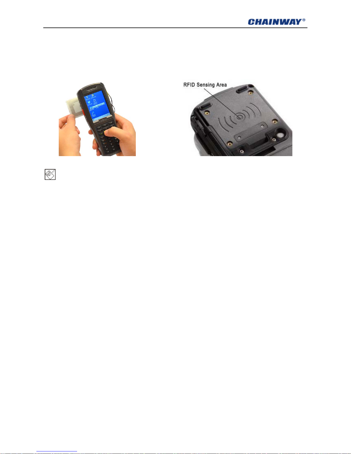
4.2 RFID Reader
The RFID sensing area is on t he back of the device (Figure4-1-2).
The RFID reader supports LF or HF, and you can choose one when ordering.
The RFID sensing range c an be from 2cm to 10cm. Different cards may have different range.
Figure4-2-1 RFID Card Reading Figure4-2-1 RFID Sensing Area
Note: one device can only support LF or HF, cannot support both at the same time
4.2.1 LF (125 kHz~134.2 kHz)
The LF (low frequency) reader supports 125kHz~134.2kHz;
Protocol: ISO11784 / 11785, FDX;
The reader supports ID card, Animal Tag, Hitag, etc. It’s recommended to send sample cards to our
factory to modify and compare it with the reader.
4.2.2 HF (13.56MHz)
The HF (high frequency) reader supports 13.56MHz;
Protocol: ISO14443A/B, ISO15693;
The reader supports HF car ds, such as S50, S70, TI, etc.
4.3 WiFi
Protocol: IEEE 802.11b/g
WiFi is a default module of our dev ic e. It allows wireless communication and real-time data transmission.
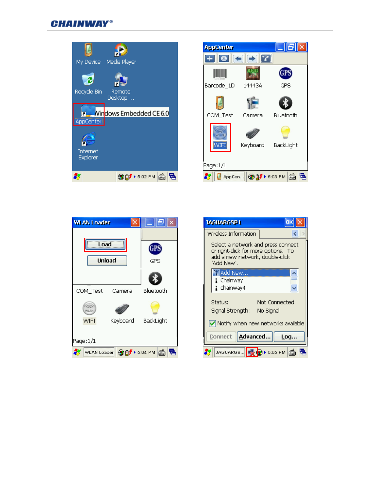
4.3.1 WiFi Configuration
1) Open AppCenter on desktop (Figure4-3-1), t hen run the application WIFI in AppCenter (Figure4-3-2);
Page 23
16
Figure4-3-1 AppCenter Figure4-3-2 WiFi Application
2) Click Load on WLAN Loader (Figure4-3-3), then network icon wil l d isplay on toolbar (Figure4-3-4);
Figure4-3-3 WLAN Loader Figure4-3-4 Network Icon
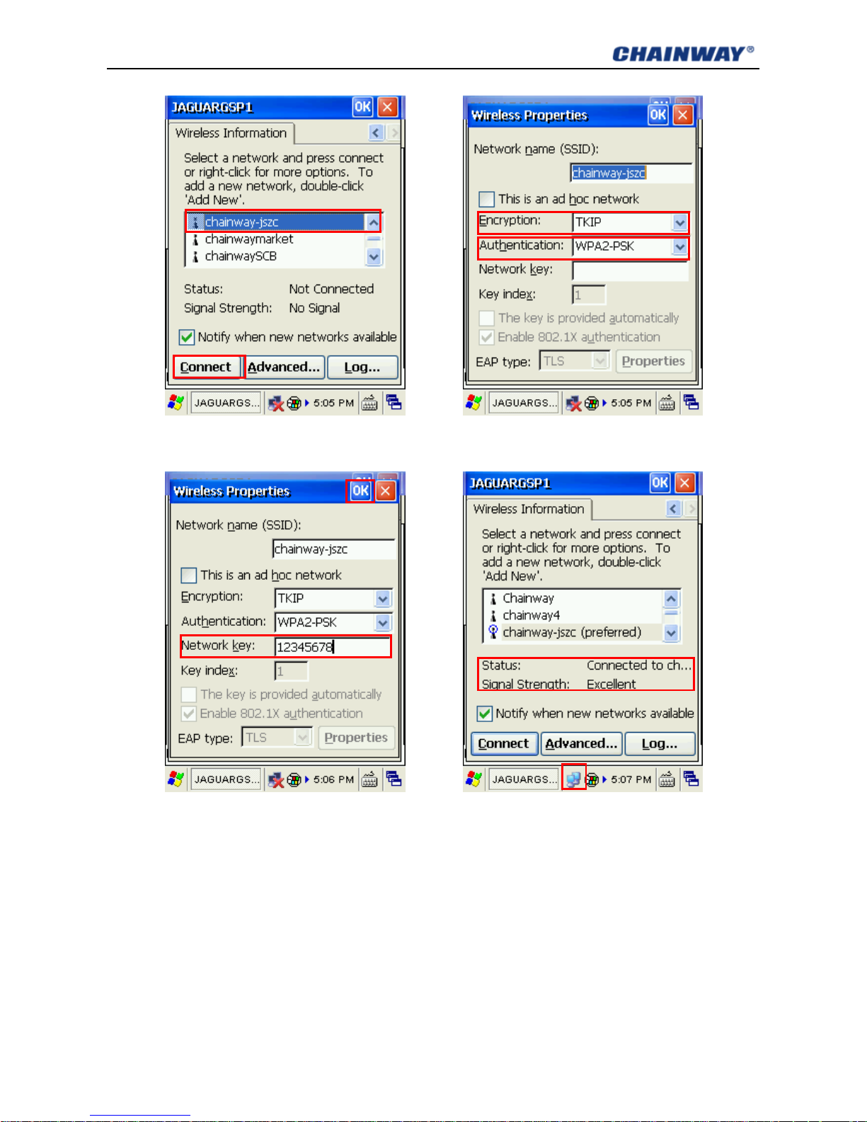
3) Double click the network icon, choose the router from Wireless Information, and then click Connect
(Figure4-3-5); choose proper Encryption and Authentication (Figure4-3-6), and type password in
Network Key, and then click OK (Figure4-3-7);
Page 24
17
Figure4-3-5 Choose Router Figure4-3-6 Wireless Properties
Figure4-3-7 Type in Password Figure4-3-8 Connected
4) If it is successful connected, the network icon will display as Figure4-3-8, and you can see the Status
and Signal Strength.
4.3.2 IP Address Setting
After connecting, double click the network icon, you can see its IP address from the tab page IP
Information (Figure4-3-9);
By default, the IP address is auto distributed by DHCP.
Page 25

18
You can specify a static IP addr ess yourself if necessary as steps below :
1) Click Start Menu-> Settings-> Network and Dial-up Connections (Figure4-3-10);
2) Double click JAGURGSP1 in Connection window (Figure4-3-11);
3) Check Specify an IP address, then type the IP Address you want, and also Subnet Mask and
Default Gateway (Figure4-3-12), and then click OK.
Figure4-3-9 IP Address Figure4-3-10 Network Connections
Figure4-3-11 Connection Icon Figure4-3-12 Static IP Address
Page 26

19
4.3.3 WiFi auto Connecting
After the device is standby or restarted, WiFi conn ection wi ll disconnect . You should Unload (Figure4-3-3)
and then Load it again.
Another way, please open My Device-> Windows (Figure4-3-13, Figure4-3-14), you can find a shortcut
pmmon and a folder Startup in it (Figure4-3-15). Copy the pmmon shortcut to StartUp folder
(Figure4-3-16) and restart the device. Next time when the device wakeup or restart, the WiFi will auto
connect.
Figure4-3-13 My Device Figure4-3-14 Windows Folder
Figure4-3-13 Copy the Shortcut Figure4-3-14 Paste to StartUp
Note: there are two files named pmmon, please copy and paste the shortcut but not the application.
Page 27

20
4.4 GPRS
The GPRS module supports G SM/GPRS (900/ 1800 MHz ). It can also suppor t 850/1900M Hz if necessar y.
Before using GPRS, make sure y our SI M c ard is ava ilabl e and you have mount ed it into the device SAM2
card slot (refer to chapter 2.3) .
4.4.1 Create and Configure Connection
1) Click Start Menu-> Settings-> Network and Dial-up Connections (Figure4-4-1), and then double
click Make New Connection (Figure4-4-2);
Figure4-4-1 Dial-up Connections Figure4-4-2 Make New Connection
2) Input connection name GPRS and then Next (Figure4-4-3); click Configure then Next (Figure4-4-4);
Figure4-4-3 Input Name Figure4-4-4 Click Configure
Page 28

21
3) In Port Settings, set Connection Preferences a s below ( Figure4-4-5):
Baud Rate: 115200; Data Bits: 8; Parity: None; Stop Bits: 1; Flow Control: None
Then click Call Options to turn to another tab page;
4) Input +CGDCONT=1,”IP”,”CMNET” (input all blue characters including the commas and quotation
marks) into Extra Settings as Figure4-4-6, the CMNET (it is the APN of China Mob ile) sh ould be r eplace d
by your local GPRS APN (Access Point Name); left others de fault, then click OK;
Figure4-4-5Port Settings Figure4-4-6 Call Options
5) Click Next to Phone Nu mber page, input Phone num ber *99***1# as Figure4-4-7, then click Finish; now
you can see the GPRS connection icon as Figure4-7-8;
Figure4-4-7 Phone Number Figure4-4-8 GPRS Connection Icon
Page 29

22
6) Double click the GPRS icon; in Dial-Up Connection page, keep User Name, Password and Domain
blank, and then click Dial Properties (Figure4-4-9); choose Location as Car and then click Edit
(Figure4-4-10); Fill the 3 edit boxes all with letter G and then OK (Figure4-4-11). Click OK on Dialing
Properties (Figure4-4-12), and then back to desktop.
Figure4-4-9 Dial-Up Connection Figure4-4-10 Dialing Properties
Figure4-4-11 Edit Dialing Patterns Figure4-4-12 Dialing Properties
4.4.2 Connect and Disconnect with GPRS
Open AppCenter, double cl ick t he application GPRS (Figure4-4-13), and then click Connect on popup
window; if connecting suc ceed, it will show Connect successfully (Figure4-4-14).
Page 30

23
Figure4-4-13 Application GPRS Figure4-4-14 Connect Succeed
You can also click Disconnect to disconnect.
Note: do not directly connect by click Connect in Dial-Up Connection window (Figure4-4-9).
4.5 Bluetooth
Our device can communicate via Bluetooth 2.0;
Run Bluetooth , and then click Activate Device (Figure4-5-1). If succeed, the button Scan Device
will be active (Figure4-5-2); click Scan Device to scan, choose the device you want to send file to, select
the file you want to send from Select File, and the click Send File. Click Exit to exit the application.
Figure4-5-1 Activate Device Figure4-5-2 Send File via Bluetooth
Page 31

24
4.6 GPS
The GPS module allows getting location dat a wher e t he dev ice now is. I t is recom men ded to use o utdoor,
because the signal is very w eak indoor, and you’d better put the device vertically with hea d up.
Run GPS from AppCenter, click Get Data (Figure4-6-1), then wait until getting data succeed. You
can see Date, UTC Time, Longitude, Latitude, Satellite Total, Effective, Begin Time, Access Time
and Spending Time from it. Click Stop to stop getting data.
Figure4-6-1 GPS Data
4.7 Camera
The camera is 3.2 mega pixels and supports max resolution 2048*1536.
Run Camera from AppCenter, check the resolution you want, default resolution is 640*480; then
click Preview to preview (Figure4-7-1), and then click Take Photo or press the button # to take photo
(Figure4-7-2). The photos will be auto saved to
Page 32

25
Figure4-7-1 Preview Figure4-7-1 Take Photo
Page 33

26
Chapter 5 Synchronization and Update
This chapter introduces how to synchronize with PC, install or remove applications for the device, update
the system and restore it to factory settings.
5.1 Synchronization with PC
5.1.1 Install Microsoft ActiveSync
We support 3 versions ActiveSync software for different OS (operation system):
ActiveSync4.5_OfficialRelease.msi
Supports OS:
Windows Server 2003;Windows Server 2003 Service Pack 1;Windows Server 2003 Service Pack 2;
Windows XP;Windows XP 64-bit;Windows XP Embedded;Windows XP Embedded Service Pack 1;
Windows XP Embedded S ervice Pack 2;Windows XP for Itanium-based Systems V ersion 2003 ;Windows
XP Home Edition ;Windows XP Media Center Edition;Windows XP Pr ofessi onal 64-Bit Editio n (Itanium);
Windows XP Professional 64-Bit Edition (Itanium) 2003;Windows X P Profess ional Editi on;Windows XP
Professional x64 Editi on;Windows XP Service Pack 1;Windows XP Serv ice Pac k 2;Windows XP Starter
Edition;Windows XP Tablet PC Edition
ActiveSync6.1_OfficialRelease-x64.exe
Supports OS(64bit):
Windows 7 Ultima te;Windows 7 Enterprise;Windows 7 Professional;Windows 7 Home Premium;
Windows Vista Ultimate;W indows Vista Enterprise;Windows Vista Business;Windows Vista Home
Premium;Windows Vista Home Basic;Windows Vista Server
ActiveSync6.1_OfficialRelease-x86.exe
Supports OS(32bit):
Windows 7 Ultima te;Windows 7 Enterprise;Windows 7 Professional;Windows 7 Home Premium;
Windows 7 Starter;Windows Vista Ultimate;Windows Vista Enterprise;Windows Vista Business;
Windows Vista Home Premium;Windows Vista Home Basic;Windows Vista Server
Please choose the right ActiveSync for your PC. You can search and download other version ActiveSync
from Microsoft website, according to you OS. After installing, you should restart your PC.
Note: when installing ActiveSync software, make sure that the device is not connected with this PC.
Page 34

27
5.1.2 Install Device Driver
When the mobile data termina l is o n, connect it with PC via USB.
For Windows 7, the driver will be auto installed. A fter that, you can see the Windows Mobile Device
Center; it shows the device it connected or not.
For Windows XP, you should install driver manually. When connecting, there will be a popup wizard,
choose the advanced option, then specify the location of driver files. After installing, the new device
will be able to use.
5.2 Install Applications
After synchronization, you can find the device from PC which named WindowsCE.
Copy the CAB file to WindowsCE, and then double click it from the device, you can install it as installing
program in Windows XP.
If the application is an exe file for Windows CE, you can copy it in and directly run it .
5.3 Update Operation System
Before updating, please backup your data: copy the data to PC or other disk like SD card. All data and
applications will be erased after updating.
5.3.1 Copy System Files to SD Card
1) Format a SD card from Window s X P;
Note: format the card from Windows XP; if from Window 7, updating will fail.
Do not choose fast format.
Choose the File System as FAT32.
2) Copy the update files into the SD card;
3) Install SD card to the dev ice (r efer t o chapter 2.2).
5.3.2 Update OS for Windows CE
After finishing steps above, restart the device, and then press F1 as soon as possible; then you
will see it as Figure5-3-1; choose Update OS, then press the yellow button on key boar d; then ple ase w ait
the system update and start.
Page 35

28
Figure5-3-1 Update OS
5.4 Restore Factory Settings
Before updating, please backup your data: copy the data to PC or other disk like SD card. All data and
applications will be erased after updating.
After finishing steps above, restart the device, and then press F1 as soon as possible; then you
will see it as Figure5-3-1; choose Restore factory settings, then press the yellow button on keyboard;
then please wait the system restor e and start.
If you choose Start OS, the system will start normally .
Page 36

29
Chapter 6 Guide for Development
This chapter introduces how t o start to develop for C5000.
6.1 Development Environment Settings
Before setting development environment, make sure you can already synchronize with PC (refer to
chapter 5.1).
6.1.1 Install C5000 SDK
1) Make sure VS2005 SP1 or VS2008 has been already installed; otherwise the SDK cannot be installed
successfully;
2) SDK File can be seen on Development Environment Setting file in SDK, find C5000.msi and double
click it (please turn off VS2005 when installing SDK), t hen it will enter interface as Figure6-1-1;
Figure6-1-1 Figure6-1-2
3) Click Next to enter Figure6-1-2;
4) In Figure6-1-2, users can read the End-User License Agreement and choose Accept and click Next
to enter Figure6-1-3 interface;
Figure6-1-3 Figure6-1-4
Page 37

30
5) In Figure6-1-3, you can fill in the blanks for User Name and Organization, when the information is
input click Next to enter Figure6-1-4;
6) In Figure6-1-4, please select Custom to enter Figure6-1-5;
Figure6-1-5 Figure6-1-6
7) In Figure6-1-5 select Documentation Entire feature will be unavailable. No need to install
Documentation infor mat ion beca use t he syst em will be like ly to go failure whi le installin g if this sect ion is
selected,Then click Next to enter Figure6-1-6;
8) Click Install in Figure6-1-6 to start installing SDK and enter Figure6-1-7;
Figure6-1-7 Figure6-1-8
9) Enter Figure6-1-8 interf ace when SDK installation is finished;
10) Click Finish in Figure6-1-8 to finish installing SDK. When installation is done, you can see C5000
ARMV4I Device on DEVICE section in Visu al St udio as Figure6-1-9.
Page 38

31
Figure6-1-9
6.1.2 Create C++ MFC Project (VS2005)
1) You need to select the programming platform for the first ti me to open VS2005, and to create a new
project when using VS2005. Click File New Project, as shown in Figure6-1-10:
Figure6-1-10
2) Select it and you’ll see the interface as Figure6-1-11.
Figure6-1-11
Page 39

32
3) Select Smart Device under New Project window, then select MFC Smart Device Application in
Templates and input project name (such as 1Dbarcode), as shown in red sections in Figure6-1-10.
4) Click OK to enter Win32 Application Wizard as Figure6-1-12.
Figure6-1-12
5) Click Next to enter SDK to select platforms (Figure6-1-13), here you can move the platform named
C5000 to the right section and the ones to the left section.
Figure6-1-13
Page 40

33
6) Click Next to enter Application Type sel ection, se lect Dialog based, Use MFC in a static library;
Resource language English (US).
Figure6-1-14
7) No need to adjust the 3 sections below, click Finish to finish creating project.
8) Choose targeted device. Rig ht cli ck in Visual Studio tool and sel ect Device.
9) Select C5000 ARMV4I Device.
10) Please confirm the ha ndheld device is synchronized with PC. Cl ic k or F5 to start programing.
Figure6-1-15
Page 41

34
6.2 Extended Serial Port Instructions
The main PCB is as Figure6-2-1.
Figure6-2-1 Main PCB
The device has 2 COM ports for user s:
COM 3: at the bottom of the device. This port can be always used by expansion module
COM 4: at the middle of the device. This port should be share with GP RS/RFID/Barcode modules.
When one module using it, others should release it.
Please check R19 & R21 when using EXT-TXD2 & EXT-RXD2, if there is empty, pls add 22Ω 0603
resistance.
The pins in Figure6-1-2 and Figure6-1-3 are feed through.
Figure6-1-2 COM Port 3 Figure6-1-2 COM Port 3
Page 42

35
Chapter 7 Malfunction and Repair
This chapter introduces some probable problems and solutions for C5000.
7.1 Equipment and System Problems
Table7-1 Equipment and System Problems
Problems Solutions
Device can’t start
Ensure the battery is correctly placed (see 2.1).
Change fully-charged battery.
Take off the battery and place again.
Touch-screen doesn’t
work
Clean the touch screen.
Recalibrate by the calibration procedure.
Restart the device
Screen fails to display
Check if the device is in standby status.
Restart the device.
Replace with fully-charged battery.
Keyboard doesn’t work
Check if the device is in standby status.
Restart the device.
Replace with fully-charged battery.
TF card can’t be identified
Check if the TF card is placed wrongly.
Check if the TF card is placed firmly.
Check if the TF card is damaged.
Restart the device.
Replace with fully-charged battery.
Battery can’t be recharged
Check if the adapter is damaged.
Check if the USB cable is damaged.
Check if the adapter is plugged into the socket (220V) .
Check if the adapter is plugged firmly.
7.2 Scanning Problems
Table7-2 Scanning Problems
Problems Solutions
Press “scan” button but
no action
Check if the scanner head is damaged.
Check if the program is correct (please refer to DEMO for specific
codes).
Page 43

36
Replace with fully-charged battery.
No data collected after
scanning
Check if the scanner head is damaged.
Check if the program is correct (please refer t o DEMO for specific
codes).
Check if the barcode is damaged.
Make sure it’s in effective operating/ scanning distance/range.
Make sure the barcode to be scanned is identifiable by the device.
Check if the scanning window is covered with dust s.
Replace with fully-charged battery.
7.3 RFID Problems
Table 7-3 RFID Problems
Problems Solutions
RFID tag can’t be
identified
Ensure the RFID module in the handheld terminal is com patible with the
tags.
Ensure the program is correct (please refer to DEMO)
Ensure the tag being scanned is within the RFID se nsing area (please
see 3.2)
7.4 Network and Communication Problems
Table 7-4 Network and Communication Problems
Problems Solutions
Can’t be recognized after USB
is connected
Ensure USB cable is plugged.
Ensure USB cable is not damaged.
Restart the device.
Pull out and reconnect the USB cable.
Check if Microsoft ActiveSync has been installed properly
(please refer the Chapter 7)
Ensure connection to PC is correct (please refer to 3.2 节)
WIFI communication error
Ensure the program is correct (Please refer to DEMO).
Ensure the setting is correct (please refer to 5.1)
Ensure the accessories come with WIFI connect ion joint, which
is in effective transm ission distance.
Page 44

37
Chapter 8 Maintenance
• Do not use non-standard recharger or batteries, which may cause damage to the device.
• Do not scrap the screen. Use the attached stylus or plastic pen-shape objects that suit touch
screens. Do not use steel pen, pencil or other sharp and hard articles on the screen.
• Use soft cloth with diluted screen detergent to clean the screen.
• Deal with used batteries according to environmental regulations. Do not throw batter into fire,
otherwise it may cause explosion.
Page 45

38
Chapter 9 AC Adapter & Battery Safety
9.1 Switching AC/DC Power Adapter Specification
Manufactory: GME TECHNOLOGY CO., LTD.
Input: AC 100~240V, 50~60Hz , 0. 28A
Output: DC 5V, 2A
Label: refer to the Figur9-1.
Figur9-1 AC Adapter Label
9.2 Battery Safety Guidelines
• The area in which the units are charged should be clear of debris and combustible materials or
chemicals. Particular care should be taken where the device is charged in a non-commercial
environment.
• Follow battery usage, storage, and c har ging guidelines found in the user’s guide.
• Improper battery use may result in a fire, explosion, or other hazard.
• To charge the mobile device battery, the battery and charger temperatures must be between +32
F and +113 F (0 and +45 C).
• Do not use incompatible batteries and chargers. Use of an incompatible battery or charger may
present a risk of fire, explosion, leakage, or other hazard. If you have any questions about the
compatibility of a battery or a charger, contact Chainway technical support.
• For devices that utilize a USB port as a charging source, the device shall only be connected to
products that bear the USB-IF logo or have completed the USB-IF compliance program.
• To enable authentication of an approved battery, as required by IEEE1725 clause 10.2.1, all
batteries will carry a Chainway hologram. Do not fit any battery without checking it has the
Page 46

39
Chainway authenticatio n hol ogr am.
• Do not disassemble or open, crush, bend or deform, puncture, or shred.
• Severe impact from dropping any battery-operated device on a hard surface could cause the
battery to overheat.
• Do not short circuit a battery or allow metallic or conductive objects to contact the battery
terminals.
• Do not modify or remanufacture, attempt to insert foreign objects into the battery, immerse or
expose to water or other liquids, or expose to fire, explosion, or other hazard.
• Do not leave or store the equipment in or near areas that might get very hot, such as in a parked
vehicle or near a radiator or other heat source. Do not place battery into a microwave oven or
dryer.
• Battery usage by children should be supervised.
• Please follow local regulations to promptly dispose of used re-chargeable batteries.
• Do not dispose of batteries in fire.
• Seek medical advice immediately if a battery has been swallowe d.
• In the event of a battery leak, do not allow the liquid to come in contact with the skin or eyes. If
contact has been made, wash the affected area with large amounts of water and seek medical
advice.
• If you suspect damage to your equipment or battery, contact Chainway to arrange for inspect ion.
Page 47

40
Chapter 10 Certification & Conformity
10.1 Certification:
The C5000 has passed CE Certificat ion. The labels should be on back of the dev ice as Figure1 0-1:
Figure10-1 CE Label
The battery label should be on t he back of the battery as Figure10-2:
Figure10-3 Battery Label
10.2 Conformity:
ETSI EN 301489-1: V1.8. 1 ( 2008-04); ETSI EN 301 489-3 V1.4.1: 2002-08
ETSI EN 301489-17: V2.1 .1 (2009-05) ; ETSI EN 300 328: V1.7.1 (2006 -10)
EN 50371:2002; ETSI EN 300 440-1:V1.6.1 (2010-08)
ETSI EN 300 440-2 V1.4.1 (2010-08) ; ETSI EN 300 330-1:V1.7.1 (2010-02)
ETSI EN 300 330-2 V1.5.1 (2010-02) ;
EN 55022: 2006+A1: 200 7 ; EN 55024: 1998+A1: 2001+A2: 2003
EN 61000-3-2: 2006+A1: 2009+A2: 2009 ; EN 61000-3-3: 2008
EN 60950-1: 2006 + A11: 2009 + A1: 2010
Page 48

41
Appendix 1 Code Types of 1D Barcode Scanner
The 1D barcode scanner can set parameters by scanning specific Function Barcodes.
Operation Steps: aim the scann er at a funct ion barcode; scan it; the laser will quic kly disapp ear if succe ed,
which shows that setting is successful.
A1.1 Supported Code Types
Appendix Table 1
Enable Disable
Code 39 Codabar IATA 2 of 5
Code 128 Discrete 2 of 5 UPC A with 2 Supps.
Interleaved 2 of 5 Code 93 UPC A with 5 Supps.
UPC A MSI UPC E0
EAN 8 Trioptic Code 39 UPC E0 with 2 Supps.
EAN 13 Bookland EAN UPC E0 with 5 Supps.
EAN 128 Code 11 EAC 13 with 2 Supps.
UPC E Chinese 2 of 5 EAN 13 with 5 Supps.
ISBT 128 UPC E1 UPC E1 with 2 Supps.
RSS-Limited UPC E1 with 5 Supps.
RSS-14 Coupon Code
RSS-Expanded
Note: the types enable / disable by default can be switched by scanning corresponding function
barcodes in Appendix Table 2.
A1.2 Transmit Code Type Character
Enable Disable
If this function enable, scanner w il l recognize code type when scanning a barcode.
Page 49

42
A1.3 Enable / Disable Barcodes
Appendix Table 2
Type
Function Barcodes Sample Barcodes
UPC-A
Enable
Disable
UPC-E
Enable
Disable
UPC-E1
Enable
Disable
EAN-8
Enable
Disable
Page 50

43
EAN-13
Enable
Disable
Bookland EAN
Enable
Disable
Code 128
Enable
Disable
UCC/EAN 128
Enable
Disable
Page 51

44
ISBT 128
Enable
Disable
Code 39
Enable
Disable
Scanning this barcode to enab le for any length Code 39
Trioptic Code 39
Enable
Disable
Page 52

45
Code 39 Full ASCII
Enable
Trioptic Code 39 and Code 39 Full ASCII cannot be enabled
simultaneously. If an error beep sounds when enabling
Trioptic Code 39, disable Code 39 Full ASCII and try again.
Disable
Code 93
Enable
Disable
Scanning this barcode to enable for any length Code 93
Code 11
Enable
Disable
Scanning this barcode to enab le for any length Code 11
Page 53

46
Interleaved 2 of 5
Enable
Disable
Scanning this barcode to enab le for any length I 2 of 5
Discrete 2 of 5
Enable
Disable
Scanning this barcode to enab le for any length D 2 of 5
Chinese 2 of 5
Enable
Disable
Page 54

47
Codabar
Enable
Disable
Scanning this barcode to enab le for any length Codabar
MSI
Enable
Disable
Scanning this barcode to enab le for any length MSI
RSS-14
Enable
Disable
Page 55

48
RSS-Limited
Enable
Disable
RSS-Expanded
Enable
Disable
 Loading...