

Page 1

CHAINTECH
ZNF3-150
NVIDIA nForce3 150
ATX Motherboard
User’s Guide
Version 1.0
Page 2

Declaration of Conformity
According to 47 CFR, Parts 2 and 15 of the FCC Rules
The following designated product:
EQUIPMENT: MAINBOARD
MODEL NO.: CT-ZNF3-150
is a Class B digital device that complies with 47 CFR Parts 2 and 15 of the FCC
Rules. Operation is subject to the following two conditions:
1. This device may not cause harmful interference.
2. This device must accept any interference received, including interference that
may cause undesired operation.
This declaration is given to the manufacturer:
CHAINTECH-EXCEL COMPUTER INC.
4427 Enterprise St. Fremont, CA 94538, U.S.A.
http://www.chaintechusa.com
Chaintech President: Simon Ho
Signature:
Page 3

Federal Communications Commission Statement
This device complies with FCC Rules Part 15. Operation is subject to the following two conditions:
* This device may not cause harmful interference.
* This device must accept any interference received, including interference that may cause undesired operation.
This equipment has been tested and found to comply with the limits for a Class B digital device, pursuant to
Part 15 of the FCC Rules. These limits are designed to provide reasonable protection against harmful interference
in a residential installation. This equipment generates, uses, and can radiate radio frequency energy. If this
equipment is not installed and used in accordance with the manufacturer's instructions, it may cause harmful
interference to radio communications. However, there is no guarantee that interference will not occur in a
particular installation. If this equipment does cause harmful interference to radio or television reception, which can
be determined by turning the equipment off and on, the user is encouraged to try to correct the interference by one
or more of the following measures:
* Reorient or relocate the receiving antenna.
* Increase the separation between the equipment and receiver.
* Connect the equipment to an outlet on a circuit different from that to which the receiver is connected.
* Consult the dealer or an experienced radio/TV technician for help.
The use of shielded cables for connection of the monitor to the graphics card is required to assure
compliance with FCC regulations. Changes or modifications to this unit not expressly approved by the party
responsible for compliance could void the user's authority to operate this equipment.
Canadian Department of Communications Statement
This digital apparatus does not exceed the Class B limits for audio noise emissions from digital apparatuses
set out in the Radio Interference Regulations of the Canadian Department of Communications.
Manufacturer's Disclaimer Statement
The information in this document is subject to change without notice and does not represent a commitment
on the part of the vendor. No warranty or representation, either expressed or implied, is made with respect to the
quality, accuracy or fitness for any particular purpose of this document. The manufacturer reserves the right to
make changes to the content of this document and/or the products associated with it at any time without obligation
to notify any person or organization of such changes. In no event will the manufacturer be liable for direct, indirect,
special, incidental or consequential damages arising out of the use or inability to use this product or documentation,
even if advised of the possibility of such damages. This document contains materials protected by copyright. All
rights are reserved. No part of this manual may be reproduced or transmitted in any form, by any means or for any
purpose without expressed written consent of it's authors. Product names appearing in this document are mentioned
for identification purposes only. All trademarks, product names or brand names appearing in this document are
registered property of their respective owners.
Printed in Taiwan.
Aug 2003
OST-CONSUMER
100%
RECYCLED PAPER
Page 4

TABLE OF CONTENTS
Chapter 1 Introduction ............................................................ 1
1-1 Product Specifications .....................................................................................1
1-2 Package Contents.............................................................................................3
1-3 CHAINTECH’s Special Features....................................................................4
1-4 ZNF3-150 Motherboard Layout ......................................................................5
Chapter 2 Hardware Setup...................................................... 6
2-1 Installing a CPU Processor in Socket 754.......................................................6
2-2 CPU Jumper Configuration .............................................................................7
2-3 Main Memory Configuration...........................................................................7
2-4 Connector and Jumper Settings .......................................................................9
2-5 CBOX™ 3 Setup ...........................................................................................21
2-6 CMC (Chaintech Multimedia Card) Setup....................................................22
硬體設定(Chinese) .................................................................. 23
2-7 安裝 CPU 在 Socket 754...........................................................................23
2-8 CPU Jumper 設定.........................................................................................24
2-9 記憶體的配置..............................................................................................24
2-10 連接座和 Jumper 設定 ..............................................................................25
2-11 CBOX™ 3 設定......................................................................................... 30
2-12 CMC (Chaintech 多媒體卡) 設定 .............................................................31
Installation Matérielle (French).............................................32
2-13 Installation d’un Processeur CPU dans le Socket 754.................................32
2-14 Configuration des Cavaliers du CPU...........................................................33
2-15 Configuration de la Mémoire Principale ..................................................... 33
2-16 Paramètres de Connecteurs et de Cavaliers.................................................34
2-17 Installation de CBOX™ 3 ...........................................................................41
2-18 Installation de CMC (Carte Multimédia Chaintech) ...................................42
Hardware-Setup(German)..................................................... 43
2-19 Installation einer CPU im Sockel 754 .........................................................43
2-20 Konfiguration der CPU-Jumper...................................................................44
2-21 Konfiguration des Hauptspeichers...............................................................44
2-22 Verkabelungs- und Jumper (Steckbrücken)-Setup ......................................45
Page 5

2-23 CBOX™ 3-Setup......................................................................................... 52
2-24 CMC (Chaintech Multimedia Card)-Setup..................................................53
Настройка аппаратных средств (Russian)........................ 54
2-25 Ус т а н о в к а процессора в разъем Socket 754.............................................54
2-26 Настройка процессора при помощи перемычек .....................................55
2-27 Конфигурация основной памяти ..............................................................55
2-28 Ус т а н о в к и соединителей и перемычек ....................................................56
2-29 Настройка панели CBOX™ 3 ................................................................... 62
2-30 Настройка CMC (Мультимедийная карта Chaintech) .............................63
하드웨어 설정 (Korean) ....................................................... 64
2-31 CPU 설정 ...................................................................................................64
2-32 CPU 점퍼 구성성 .....................................................................................65
2-33 주 메모리 구성........................................................................................65
2-34 커넥터 및 점퍼 셋팅..............................................................................66
2-35 CBOX™ 3 설정......................................................................................... 71
2-36 CMC (Chaintech Multimedia Card) 설정..................................................72
Chapter 3 BIOS Setup Program............................................ 73
3-1 Standard CMOS Setup...................................................................................74
3-2 Advanced BIOS Features ..............................................................................75
3-3 Advanced Chipset Features ........................................................................... 78
3-4 Integrated Peripherals....................................................................................80
3-5 Power Management Setup............................................................................. 83
3-6 PNP/PCI Configurations................................................................................86
3-7 PC Health Status............................................................................................87
3-8 Frequency/Voltage Control............................................................................88
3-9 Load Fail-Safe Defaults.................................................................................89
3-10 Load Optimized Defaults.............................................................................89
3-11 Supervisor Password & User Password Setting ..........................................90
3-12 Save and Exit Setup.....................................................................................90
3-13 Exit Without Saving ....................................................................................90
BIOS 設定 (Chinese).............................................................. 91
3-14 基本 CMOS 設定.....................................................................................92
3-15 BIOS 功能設定..........................................................................................93
3-16 進階晶片組的設定....................................................................................95
Page 6

3-17 內建周邊裝置設定....................................................................................96
3-18 電源管理設定........................................................................................99
3-19 PNP/PCI 功能設定................................................................................101
3-20 電腦狀態..................................................................................................102
3-21 電壓頻率的控制...................................................................................103
3-22 載入原始設定..........................................................................................104
3-23 載入快速設定......................................................................................104
3-24 管理人密碼或使用者密碼設定..............................................................105
3-25 存檔或離開設定..................................................................................105
3-26 離開不存檔...........................................................................................105
Programme Setup du BIOS (French) ................................. 106
3-27 Standard CMOS Setup (Setup du CMOS Standard) .................................107
3-28 Advanced BIOS Features (Fonctionnalités Avancées du BIOS)...............108
3-29 Advanced Chipset Features (Fonctionnalités Avancées du Chipset) ........111
3-30 Integrated Peripherals................................................................................113
3-31 Power Management Setup (Paramétrage de Gestion d’Alimentation)......116
3-32 PNP/PCI Configurations............................................................................119
3-33 PC Health Status........................................................................................120
3-34 Frequency/Voltage Control........................................................................121
3-35 Load Fail-Safe Defaults.............................................................................122
3-36 Load Optimized Defaults (Charger les Valeurs par Défauts Optimisées) .122
3-37 Supervisor Password & User Password Setting (Paramétrage de Mot de
Passe Superviseur & Mot de Passe Utilisateur).................................................123
3-38 Save and Exit Setup (Enregistrer et Quitter le menu Setup) .....................123
3-39 Exit Without Saving (Quitter sans Enregistrer).........................................123
BIOS Setup Program (German).......................................... 124
3-40 Standard CMOS Setup...............................................................................125
3-41 Advanced BIOS Features(Erweiterte BIOS Funktionen)..........................126
3-42 Advanced Chipset Features(Erweiterte Chipsatz Funktionen)..................129
3-43 Integrated Peripherals(Integrierte Peripherigeräten) .................................131
3-44 Power Management Setup(Stromführungseinstellungen).........................134
3-45 PNP/PCI Configurations(PNP/PCI Einstellungen) ...................................138
3-46 PC Health Status(PC Gesundheitszustand) ...............................................139
3-47 Frequency/Voltage Control(Frequenz/Spannungs Einstellung) ................140
3-48 Load Fail-Safe Defaults(Fehl-Sicher Standartwerte laden).......................141
3-49 Load Optimized Defaults(Optimierten Standartwerte laden)....................141
Page 7

3-50 Supervisor Password & User Password Setting(Supervisor- und Nutzer
-Paßwort Einstellungen).....................................................................................142
3-51 Save and Exit Setup(Speichern und Setup verlassen) ...............................142
3-52 Exit Without Saving(Beenden ohne zu speichern)....................................142
Программа настройки BIOS (Russian)............................ 143
3-53 Раздел Standard CMOS Setup ..................................................................144
3-54 Advanced BIOS Features (Расширенные возможности BIOS)..............145
3-55 Advanced Chipset Features (Расширенные настройки набора микросхем)
............................................................................................................................148
3-56 Integrated Peripherals (Встроенные периферийные устройства) .........150
3-57 Power Management Setup (Настройка управления питанием) .............153
3-58 PNP/PCI Configurations (Конфигурации PNP/PCI)...............................156
3-59 PC Health Status (Состояние здоровья ПК)............................................157
3-60 Frequency/Voltage Control (Управление частотой / напряжением)......158
3-61 Load Fail-Safe Defaults (Загрузить безопасные настройки по
умолчанию).......................................................................................................159
3-62 Load Optimized Defaults (Загрузить оптимизированные настройки по
умолчанию).......................................................................................................159
3-63 Supervisor Password & User Password Setting (Ус т а н о в к а пароля
администратора и пользователя) ....................................................................160
3-64 Save and Exit Setup (Сохранить и выйти) ..............................................160
3-65 Exit Without saving (Выйти без сохранения) .........................................160
BIOS 설정 프로그램 (Korean)........................................... 161
3-66 기본 CMOS 설정...................................................................................162
3-67 BIOS 기능 설정......................................................................................163
3-68 Chipset 기능설정.....................................................................................165
3-69 주변기기 설정........................................................................................167
3-70 전원 관리 기능 설정............................................................................170
3-71 PNP/PCI 구성...........................................................................................173
3-72 PC Health 상태.........................................................................................174
3-73 Frequency/Voltage 조정...........................................................................175
3-74 안정된 설정 불러오기..........................................................................176
Chapter 4 Driver Setup........................................................ 178
4-1 NVIDIA Driver Setup .................................................................................178
4-2 Audio Driver Setup......................................................................................182
Page 8

4-3 Gigabit LAN Driver Setup ..........................................................................185
4-4 SATA Driver................................................................................................186
4-5 USB 2.0 Driver (1) ......................................................................................187
4-6 USB 2.0 Driver (2) ......................................................................................188
4-7 WinCinema Pro ...........................................................................................191
Appendix................................................................................ 204
A-1 Digidoc 80-Port POST Error Code List......................................................204
A-2 DigiDoc.......................................................................................................209
A-3 Image It.......................................................................................................210
A-4 ProMagic 6.0...............................................................................................218
A-5 Memory Test for AMD Althon 64 – 3400+................................................226
A-6 Envy 24PT Family Audio Controller .........................................................230
How To Contact CHAINTECH........................................... 236
Page 9

Chapter 1
Chapter 1
1-1 Product Specifications
CPU
- Supports new generation AMD Socket-754 Athlon 64 CPU
- Processor interface via 6.4GB/s Hyper Transport bus
Chipset
- NVIDIA nForce3 150
Main Memory
- Supports three 184- pin DDR DIMMs up to 2GB
- Supports DDR266/333/400 memory
Expansion Slots
- One 1.5V AGP slot for 8X/4X AGP
- Five 32-Bit PCI slots (v2.2 compatible)
- One CMR (Chaintech Multimedia Raiser) for Chaintech Multimedia Card
Introduction
(CMC 7.1)
7.1 Channel Audio
- 24-bit resolution audio format support
- Sampling rates up to 96 KHz
- Multi-channel AC-link supported alternatively
- Supports S/PDIF out
SATA RAID
- On-board Sil3114 SATA RAID Controller supports 4 Serial ATA devices for
the highest data transfer rates (1.5 Gbps burst) with RAID 0/1/5/10 solutions.
IDE
- Build-in nForce3 150 supports 3 ATA-66/100/133 IDE Ports
USB 2.0
- Build-in nForce3 150 supports total 6 USB 2.0/1.1 ports with High-Speed
Device @ 480 Mb/s Transfer Rates
IEEE1394
- On-board VIA VT6306 IEEE1394 Host Controller supports 3 IEEE1394 ports
with Serial bus data rates of 100, 200 and 400Mbps
- IEEE P1394a compliant and IEEE Std. 1394-1995
1
Page 10

Chapter 1
Gigabit Ethernet
- On -board Broadcom GbE Controller supports 10/100/1000 Base-T Gigabit
LAN
Super I/O & System Monitoring
- 2 temperatures sensing for CPU and system
- 3 Fan speed monitoring (CPU, System and Chipset)
- Two UARTs support two serial ports
- One SPP/ECP/EPP parallel port
- One FDD connector supports up to 2.88MB
Boot-Block Flash ROM
- Award system BIOS support PnP, APM, DMI, ACPI, & Multi-device booting
features
Rear Panel I/O ports
- One PS/2 Mouse and Keyboard port
- Two USB ports and one RJ45 connector
- Two 9-pin D-sub male Serial ports
- One 25-pin D-sub female Parallel port
- Audio I/O jacks (Line-in, Lin-out and Mic-in)
2
Page 11

1-2 Package Contents
This product comes with the following components:
1.
Motherboard x 1
2.
I / O Shield x 1
3. Cables:
- IDE Round Cable x 2
- Floppy Round Cable x 1
4. Serial ATA Cable x 4
5. Serial ATA Power Cable x 2
6.
CMC (Chaintech Multimedia Card) x 1
7.
Manual
Include:
- User’s Guide (English &Multi-language) x 1
- EZ Manual x 1
Chapter 1
8. Driver CD
x 1
9. Value-pack 2003 x 1
a) Norton Anti Virus
b) ProMagic
c) Image It
10.
Thermal grease pack x 1
11. CBOX3™ Package
Include:
- 5-1/4” CBOX™3 x 1
- USB 10-pin Cable x 2
- Front Audio 10-pin Cable x 1
- 80-Port 10-pin Cable x 1
- IEEE-1394 8-pin Cable x 1
- Zenith Emblem x 1
- Digidoc 80-Port POST Error Code List x 1
- Front-Panel Shield x 2
3
Page 12
Chapter 1
1-3 CHAINTECH’s Special Features
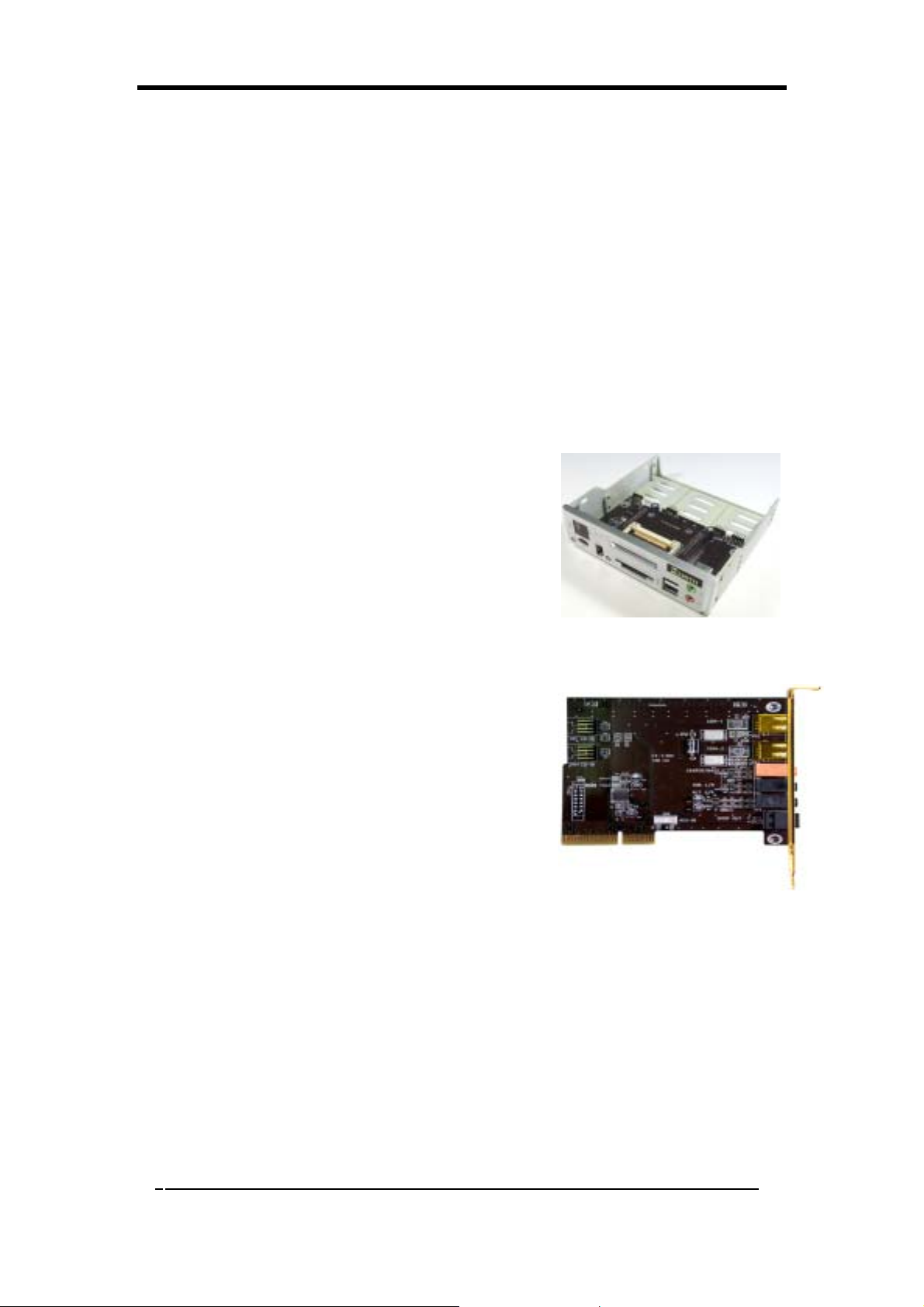
CBOX™ 3
- Fits in any 5-1/4” drive bay
- “DigiDoc” displays CPU’s temperature and 80-port Post Code during POST
at boot up
- Integrates 6 in 1 Card Reader with USB 2.0 standard for high-speed data
transfer.
- Organized ports including 2-port USB 2.0, IEEE1394, Headphone and
Microphone
Include:
- USB (1.1 / 2.0 compliant) Ext. ports x 2
- Earphone (∅ 3.5mm) phone jack x 1
- MIC – in (∅ 3.5mm) phone jack x 1
- IEEE-1394 Ext. port x 1
- DigiDoc System Monitoring Display x 1
- 6 in 1 Card Reader x 1
CMC 7.1 (Chaintech Multimedia Card)
CMC which fits right into Chaintech proprietary
CMR (Chaintech Multimedia Riser) integrates most
multimedia functions within one card, including two
IEEE 1394 ports, three Audio jacks for 7.1 channel
surround and one S/PDIF port for digital audio
output.
4
Page 13
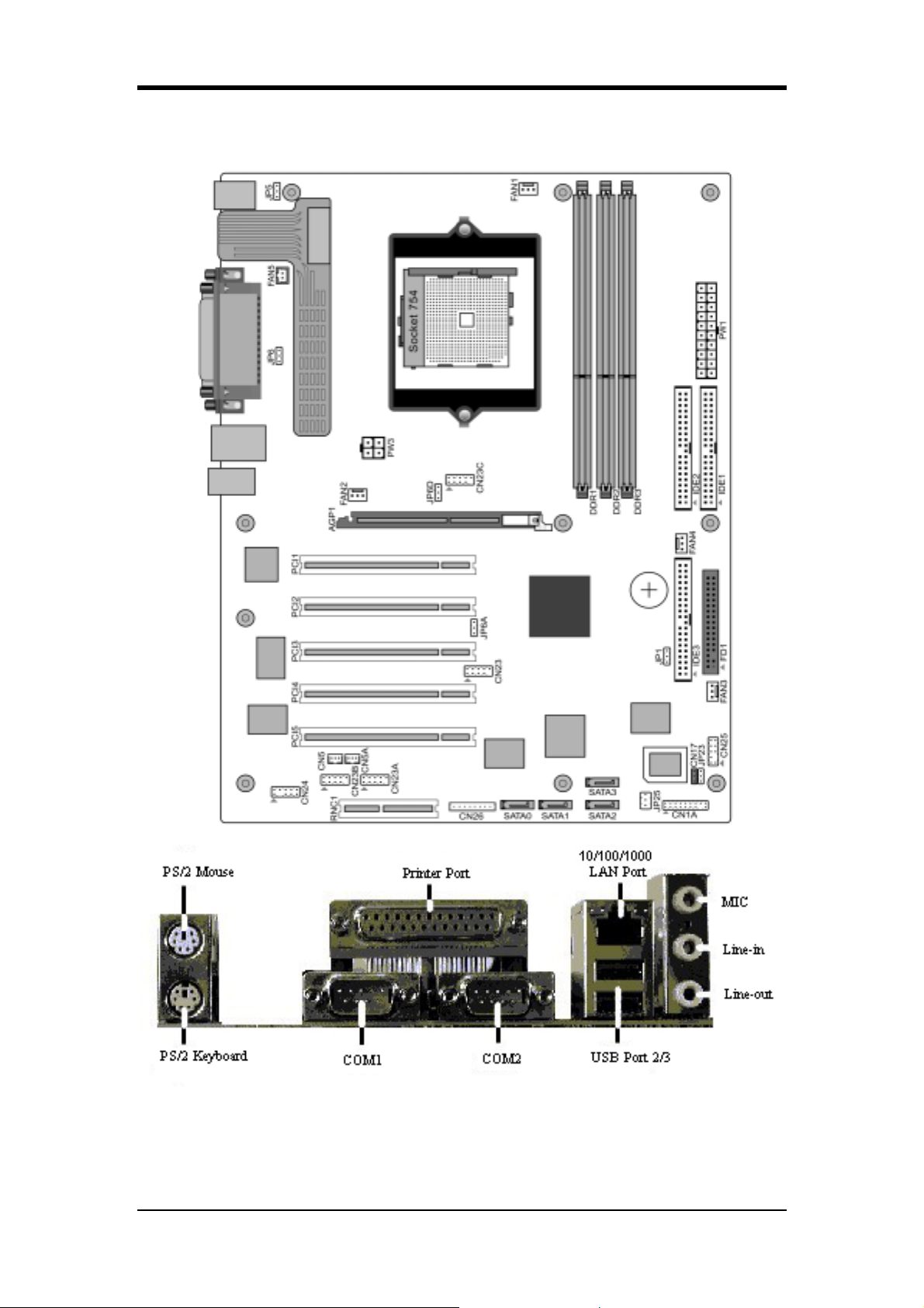
1-4 ZNF3-150 Motherboard Layout
Chapter 1
5
Page 14
Chapter 2
Chapter 2
Hardware Setup
If your motherboard has already been installed in your computer you may still need
to refer to this chapter if you plan to upgrade your system's hardware.
This motherboard is electrostatic sensitive. Do not touch without wearing proper
safety gadget and make sure to disconnect the power cable from the power source
before performing any work on your motherboard. Not doing so may result in
electrical shock!
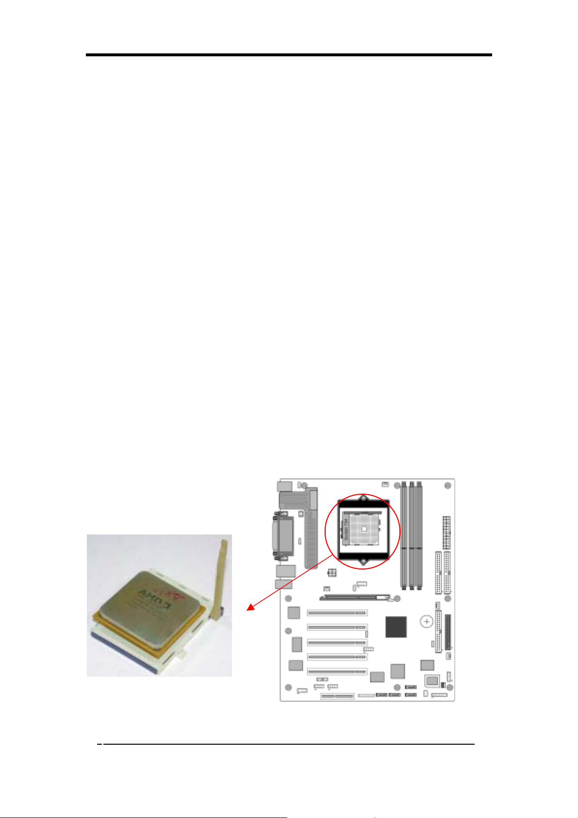
2-1 Installing a CPU Processor in Socket 754
The Socket 754, designed for AMD Athlon 64 processors, has been incorporated as
a standard motherboard specification. To insert your CPU into Socket 754 please do
the following:
1. Locate a cut edge on the top surface of the CPU, which is close to one of the
CPU corners. The same corner will also be cut off, leaving a noticeable notch
in the CPU's corner. These markings indicate Pin 1 on the CPU.
2. Pull up the lever of Socket 754 so that it is perpendicular with the surface of
the motherboard. Gently insert the CPU with Pin 1 at the same corner of
Socket 754, which is located close to the end of the lever. Allow the weight
of the CPU to push itself into place. Do not apply extra pressure as doing so
may result in damaging your CPU. Snap the lever back into place.
3. Installing an AMD approved heat sink with cooling fan is necessary for
proper heat dissipation from your CPU. Failing to install these items may
result in overheating and possible burn-out of your CPU.
Notes: In order to boot up with a newly installed CPU, AC Power must be switched off
before installation.
6
Page 15
Chapter 2
2-2 CPU Jumper Configuration
Frequency Configuration:
This frequency is adjusted by CPU automatically.
2-3 Main Memory Configuration
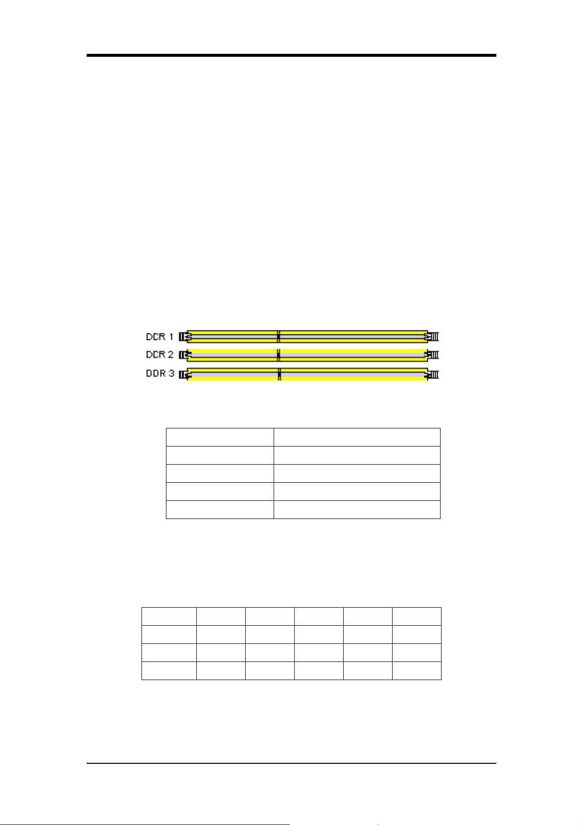
The DDR SDRAM memory system consists of three DIMMs. The first bank
supports up to 1GB of memory, and the second and third ones together support up to
1GB of memory in total.
We strongly suggest that you install DRAMs in either
DIMM1 + DIMM2 or DIMM1 +DIMM3 slots. Installation in DIMM2 + DIMM3
slots is not recommended since it may result an unstable system.
Please refer to Appendix for a DDR SDRAM compatibility chart.
DDR SDRAM Specifications
Memory Frequency Internal System BUS Frequency
100 MHz 200 MHz
133 MHz 266 MHz
166 MHz 333 MHz
200 MHz 400 MHz
DIMM type: 2.5V, unbuffered 184 pin 64/128/256/512-bit DDR SDRAM
Module size: Single/double-sided 64/128/256/512MB/1GB
Parity: Either parity or non-parity
Location 64 MB 128 MB 256 MB 512 MB 1.0 GB
DDR 1 V V V V V
DDR 2
V
V V V V
DDR 3 V V V V V
Please refer to Appendix for detailed information on DDR DRAM Support.
7
Page 16

Chapter 2
AMD Hyper-Transport ™ Technology
HyperTransport technology is a high-speed, low latency, point-to-point link
designed to increase the communication speed between integrated circuits in
computers, servers, embedded systems, and networking and telecommunications
equipment up to 48 times faster than some existing technologies.
HyperTransport technology helps reduce the number of buses in a system, which
can reduce system bottlenecks and enable today's faster microprocessors to use
system memory more efficiently in high-end multiprocessor systems.
HyperTransport technology is designed to:
- Provide significantly more bandwidth than current technologies
- Use low-latency responses and low pin counts
- Maintain compatibility with legacy PC buses while being extensible to new SNA
(Systems Network Architecture) buses.
- Appear transparent to operating systems and offer little impact on peripheral
drivers.
8
Page 17
Chapter 2
2-4 Connector and Jumper Settings
Connectors are used to link the system board with other parts of the system,
including power supply, keyboard, and the various controllers on the front panel of
the system case.
The power supply connector is the last connection to be made while
installing a motherboard. Before connecting the power supply, please
make sure it is not connected to the power source.
All cables that provided by CHAINTECH come with a security-proof.
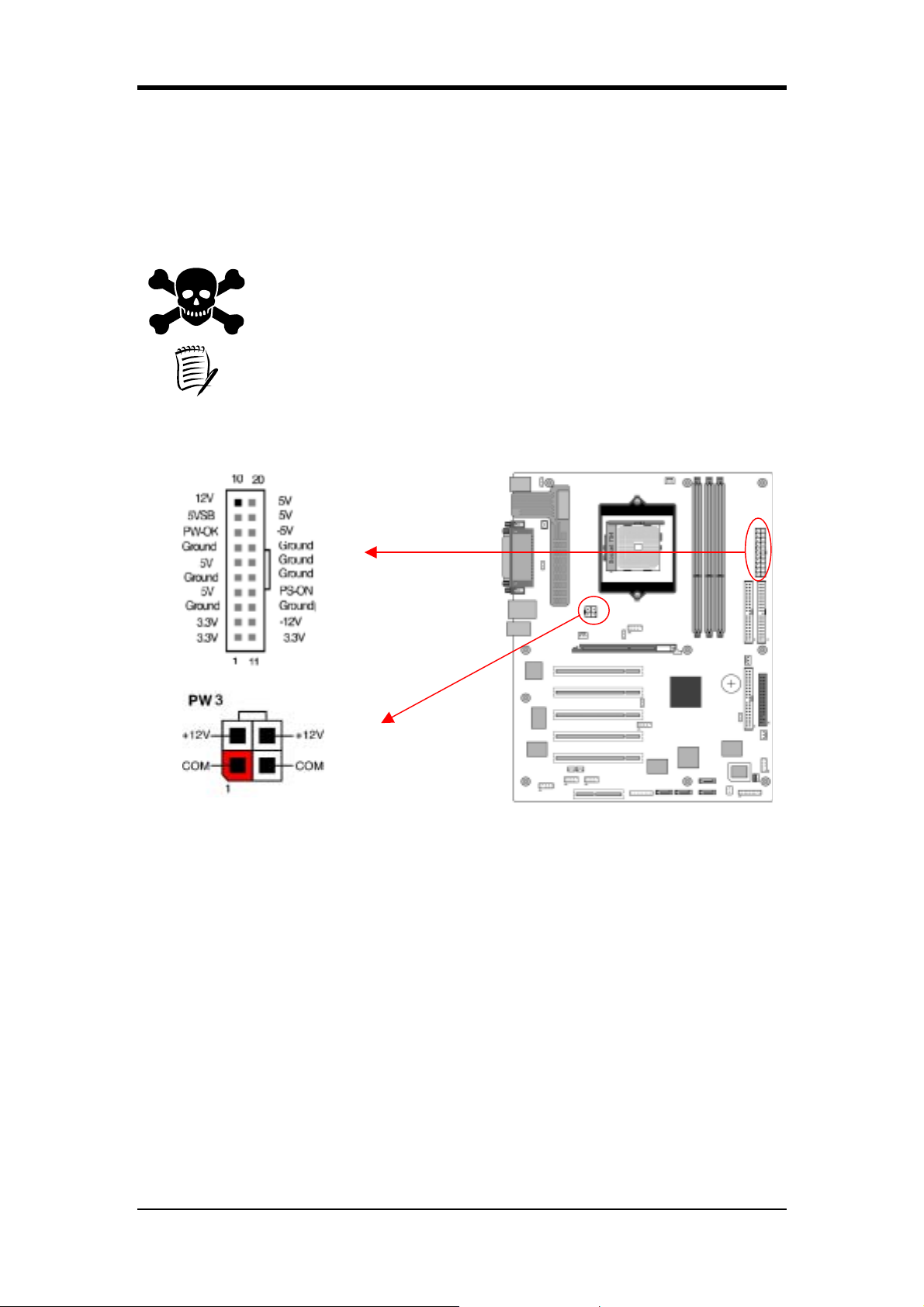
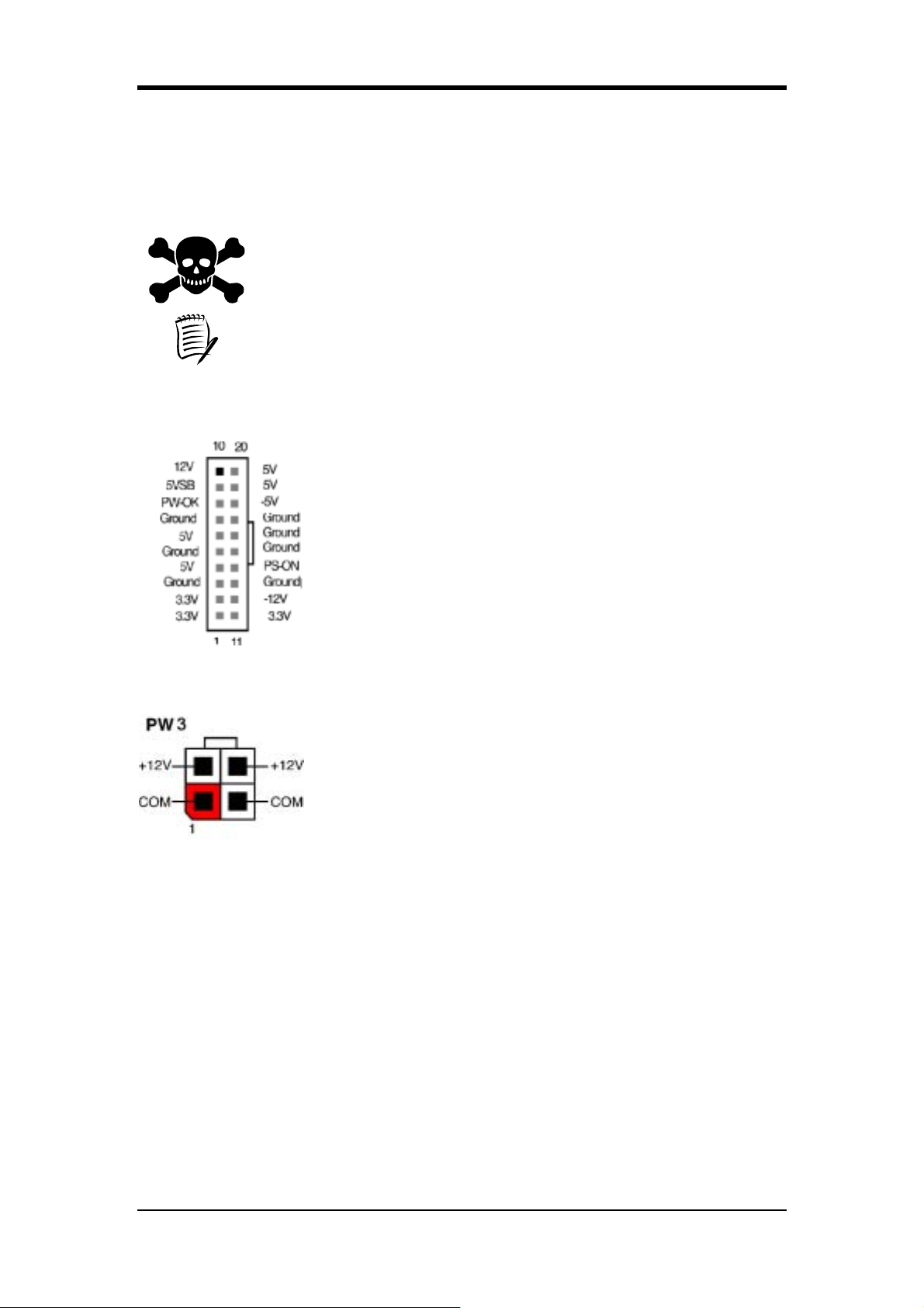
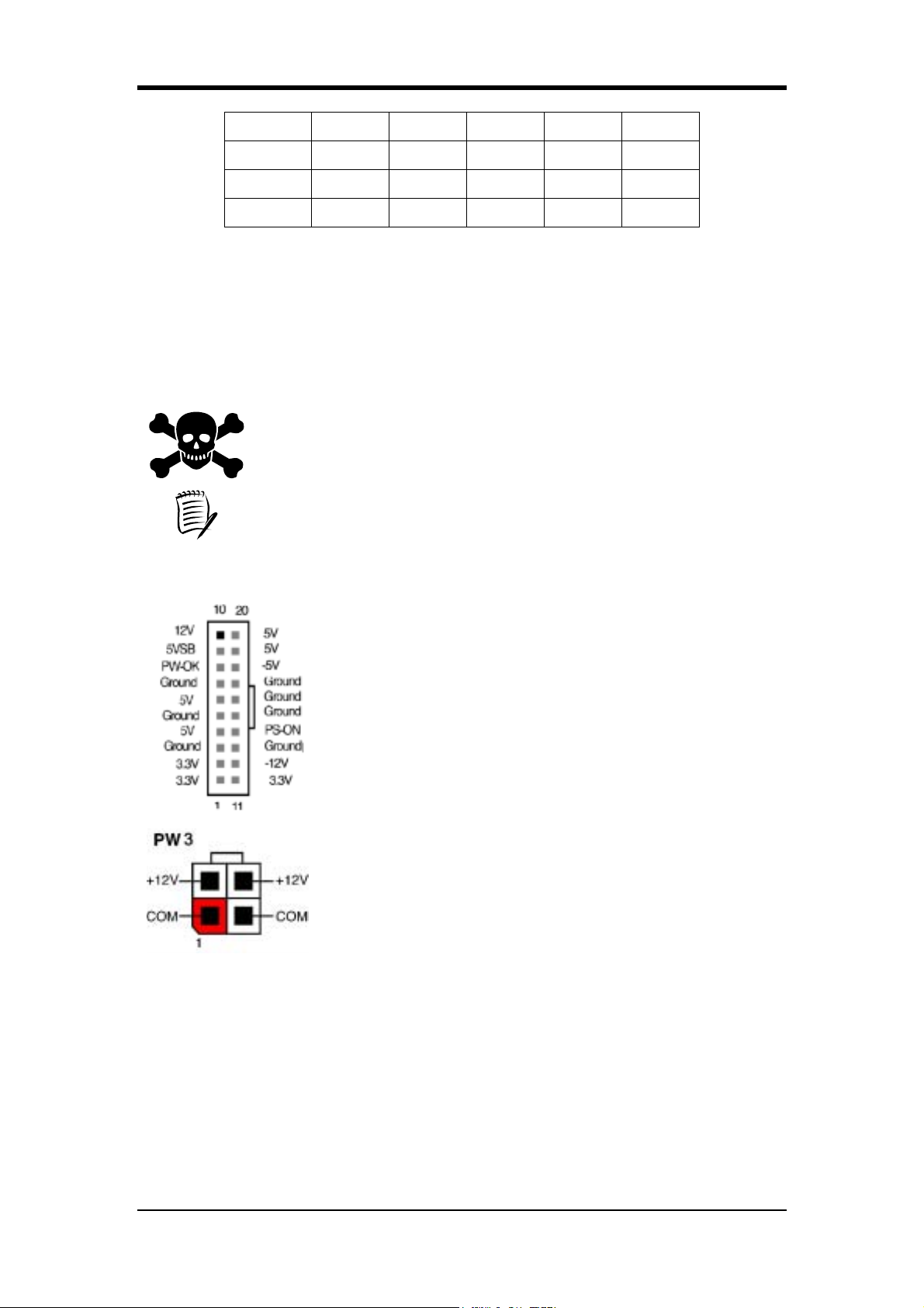
PW 1 / 3 (ATX Power Supply Connector):
The power cord leading from the system's power supply to the external power
source must be the very last part connected when assembling a system. The ATX
power supply provides a single 20-pin connector interface, which incorporates
standard +/-5V, +/-12V, optional 3.3V and Soft-power signals. The Soft power signal,
a 5V trickle supply is continuously supplied when AC power is available. When the
system is in Soft-Off mode, this trickle supply maintains the system in its minimum
power state.
The ATX 12V power supply has a new +12V (4-pin) and +5V / 3.3V (6-pin)
auxiliary power connector to enable the delivery of more +12 VDC and + 5/ 3.3V
VDC current to the motherboard.
Power-On By Modem:
While in Soft-Off state, if an external modem ring-up signal is detected, the system
will be activated and therefore can be remotely accessed. You may enable this
function in BIOS's Power Management Setup menu. (See section 3. 5)
9
Page 18
Chapter 2
Blinking LED in Suspend Mode:
While in Suspend mode, the LED light on the front panel of your computer will
flash. Suspend mode is entered by pressing the Green Override Power Button on
your ATX case, or by enabling the Power Management and Suspend Mode options
in BIOS's Power Management menu. (See section 3.5)
Poly-fuse Over Current Protection:
The poly-fuse protects the system from dangerous voltages that the system might be
exposed to via keyboards or USB connectors. In case of such an exposure, the
poly-fuse will immediately be disconnected from the circuit just like a normal fuse.
After being disconnected for a certain period of time, the poly-fuse will return to its
normal state and the keyboard or USB connector can function properly again.
Unlike conventional fuses, the poly-fuse will not need to be replaced, relieving users
from such inconveniences.
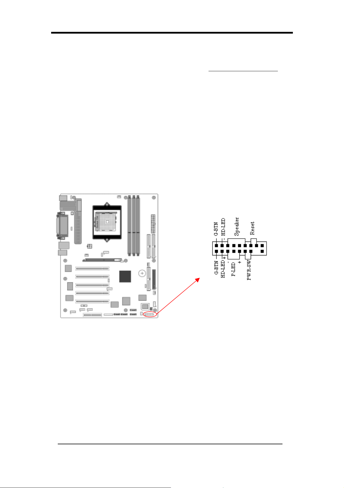
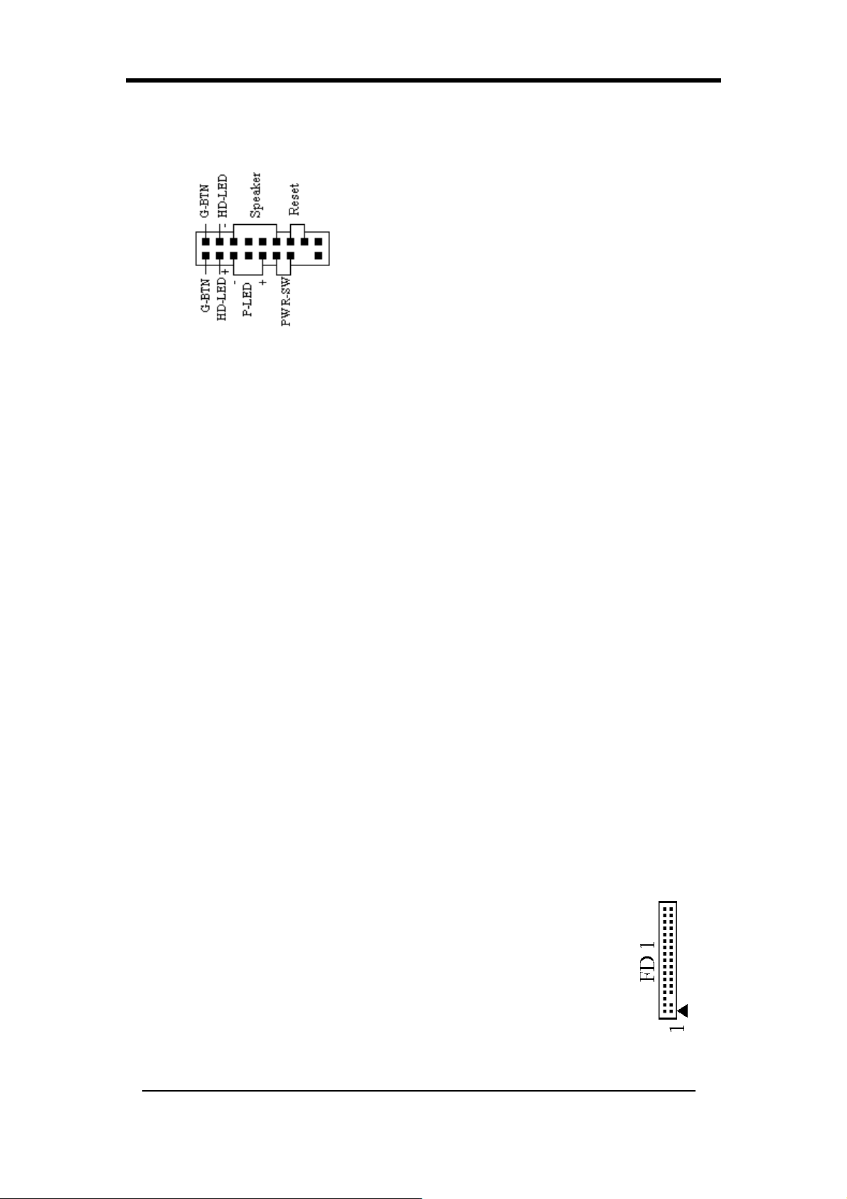
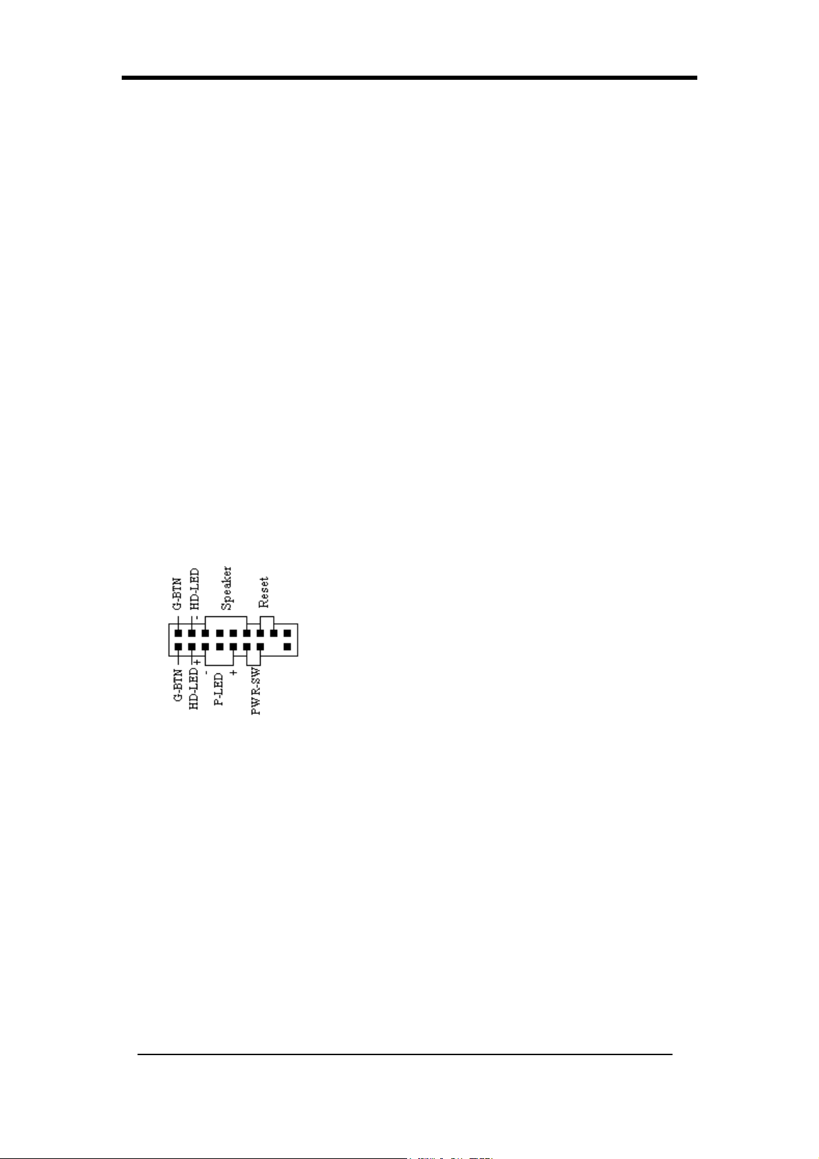
CN1A (Front Panel Connector):
1.
PWR-SW (Over-ride Power Button Connector):
The power button on the ATX chassis can be used as a normal power switch
as well as a device to activate the Advanced Power Management Suspend
mode. This is a power-saving mode used for saving electricity when the
computer is idle for long periods of time. The Soft-OFF by PWR-BTTN
function in BIOS's Power Management Setup menu must be set to [Delay 4
Sec.] to activate this function.
When the Soft-OFF by PWR-BTTN function is enabled, pressing the power
button rapidly will switch the system to Suspend mode. Any occurrence of
external activities such as pressing any keys on the keyboard or moving the
mouse will bring the system back to Full-On. Pushing the button while in
10
Page 19
Chapter 2
Full-On mode for more than [4 seconds] will switch the system completely
off. See Over-ride Power Button Operation diagram.
2.
P-LED (Power LED Connector):
The power indicator LED shows the system's power status. It is important to
pay attention to the correct cable and pin orientation (i.e. Be careful not to
reverse the order of these two connectors.)
3.
G-BTN (Green Button Switch):
Some ATX cases provide a Green button switch, which is used to put the
system in Suspend mode. While in Suspend mode, the power supply to the
system is reduced to a trickle, the CPU clock is stopped, and the CPU core is
in its minimum power state. The system is activated whenever the keyboard
or mouse is touched. The system will resume in various ways as defined by
Power Management Setup screen in BIOS.
4.
RESET (System Reset Switch Connector):
This connector should be connected to the reset switch on the front panel of
the system case. The reset switch allows you to restart the system without
turning the power off.
5.
SPEAKER (Speaker Connector):
This 4-pin connector connects to the case-mounted speakers.
6.
HD-LED (IDE - Activity LED Connector):
The IDE- activity LED lights up whenever the system reads/writes to the
IDE devices.
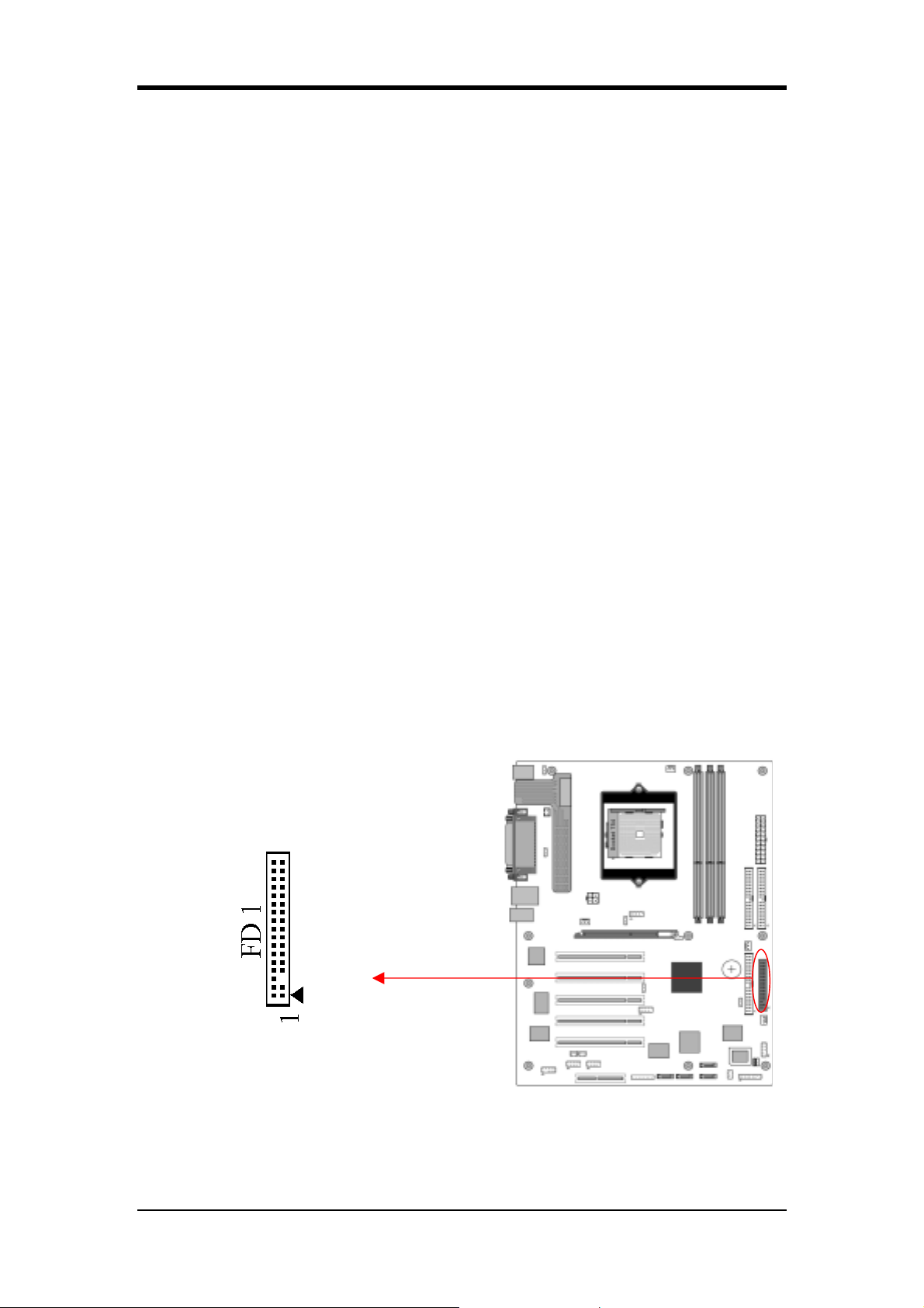
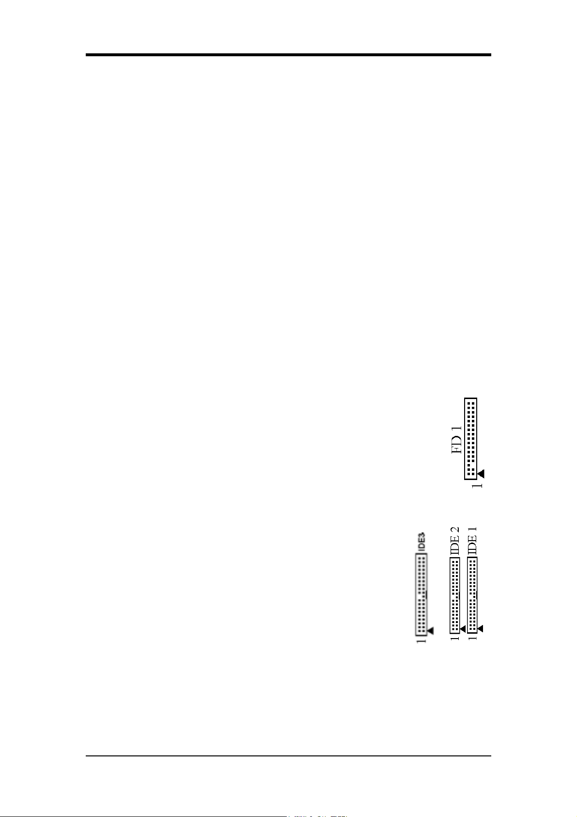
FD1 (Floppy Connector):
The motherboard provides a standard floppy disk drive connector that supports
360K, 720K, 1.2M, 1.44M and 2.88M floppy disk types. It is connected to a floppy
disk drive of 34 pins.
11
Page 20
Chapter 2
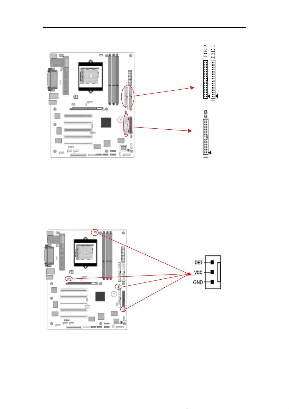
IDE 1/2/3 (IDE Hard-Disk Connector):
The motherboard has a 32-bit Enhanced PCI IDE and Ultra ATA66/100 controller
that provides PIO mode 0~4, Bus Master, and Ultra ATA66/100 function. This
connector is used for connecting 40 pins of ATAPI devices.
IDE 1 only connects two IDE devices. (Primary Master/Slave)
IDE 2 only connects two IDE devices. (Secondary Master/Slave)
IDE 3 only connects two IDE devices. (Tertiary Master/Slave)
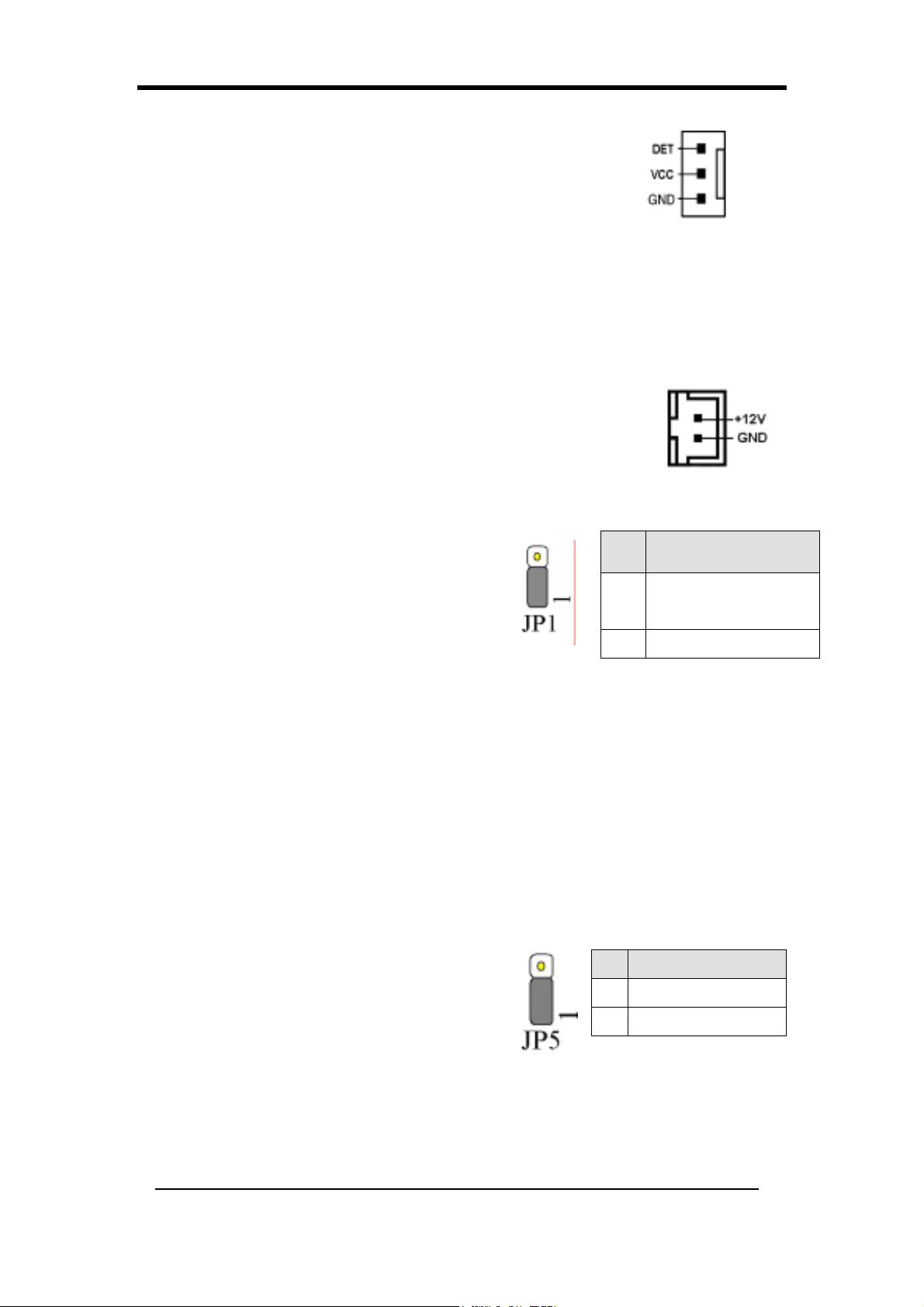
FAN1/2/3/4 (CPU/System/ Case Fan /Chip Fan Connectors):
The board's hardware management is able to detect the CPU and system fan speed in
rpm (revolutions per minute). The wiring and plugging may vary depending on the
manufacturer. On standard fans, the red is positive (+12V), the black is ground, and
the yellow wire is the rotation signal. Connect the north-bridge cooling fan to FAN4.
12
Page 21
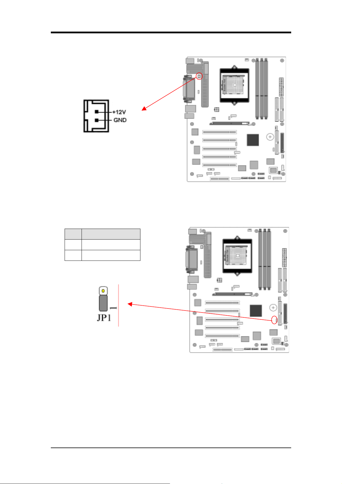
FAN 5 (Heat-Pipe connector)
This connector is used to connect heat-pipe to the motherboard.
Chapter 2
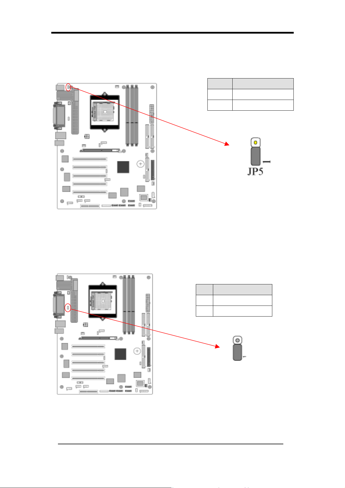
JP1 (CMOS Clear Jumper):
Pin Definition
1-2 Normal (default)
2-3 Clear CMOS Data
There is a CMOS RAM on board that has a power supply from external battery to
keep the data and system configuration. To clear the contents of the CMOS, please
follow the steps below.
1.
Disconnect the system power supply from the power source.
2.
Set the jumper cap at location [2-3] for <5 seconds>, and then set it back to
the default position.
3.
Connect the system's power and then start the system.
4.
Enter BIOS's CMOS Setup Utility and choose Load Optimized Defaults.
13
Page 22
Chapter 2
Type [Y] and then press [Enter] to continue.
5. Set the system configuration in the Standard CMOS Setup menu.
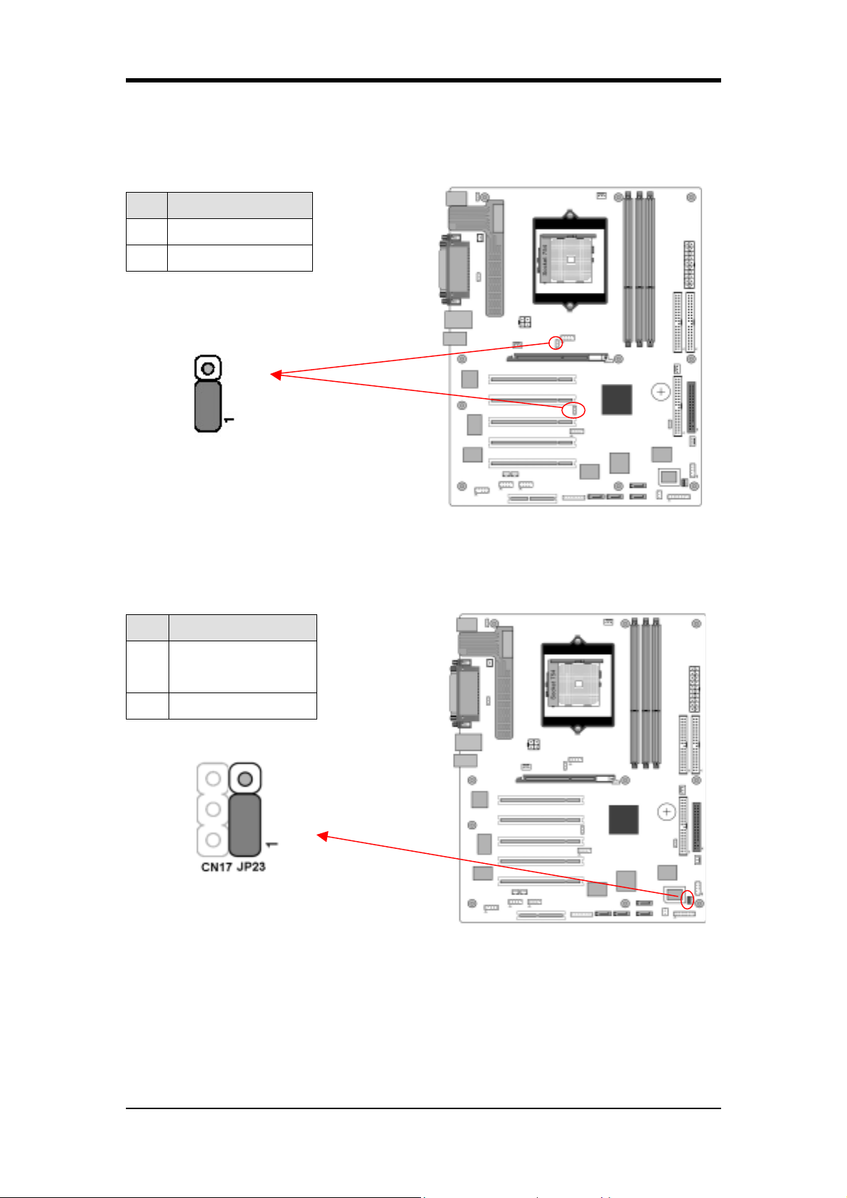
JP5 (KB/MS Power On)
Pin Definition
1-2 Disable
2-3 Enable
This board can be turned on by the PS / 2 keyboard (hot key). To use this function,
select a hot key of your choice at the Hot Key Power ON option under Wake Up
Events in the BIOS's Power Management Setup screen. You must also set this
jumper's cap to pins [2-3] to use this function.
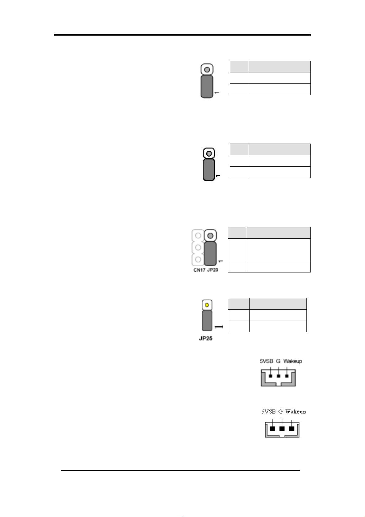
JP6 (Power On by USB 2/3)
Pin Definition
1-2 Disable
2-3 Enable
JP6 USB 2/3
An USB keyboard hot key or an USB mouse-click can activate this board. To use
this function, select a hot key of your choice at the USB Resume from S3 option
under Wake Up Events in the BIOS's Power On Management screen. You must also
set this jumper's cap to pins 2-3 to use this function.
14
Page 23
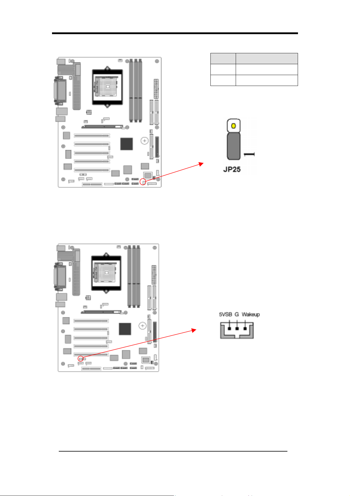
JP 6A/ 6D (Enable/Disable USB 4/5, 0/1 Device Power ON Jumper)
JP6A USB 4/5, JP6D USB 0/1
Pin Definition
1-2 Disable
2-3 Enable
Chapter 2
A USB keyboard hot key or a USB mouse click can turn on this board. You must
also set this jumper's cap to pins 2-3 to use this function.
JP23 (Green Mode LED):
Pin Definition
CHAINTECH
1-2
(default)
2-3 OEM
This cap is to setup Green LED flash mode. (Optional)
15
Page 24
Chapter 2
JP25 (ROM Table Select): Optional
Pin Definition
1-2 User mode
2-3 Safe mode
The system enters User Mode when jumper caps are left at pins [1-2] during the
boot up process. Otherwise Safe Mode is entered when jumper caps are left at pins
[2-3].
CN5 [WOL (Wake-on-LAN) Connector]:
Enable the Wake Up On LAN selection in BIOS's Power Management Menu to use
this function. The capability to remotely manage PCs over networks is a significant
factor in reducing administrative and ownership costs. Magic Packet technology is
designed with WOL ability to LAN controllers. This header is used to connect an
add-in NIC (Network Interface Card) that provides WOL function to the
motherboard.
16
Page 25
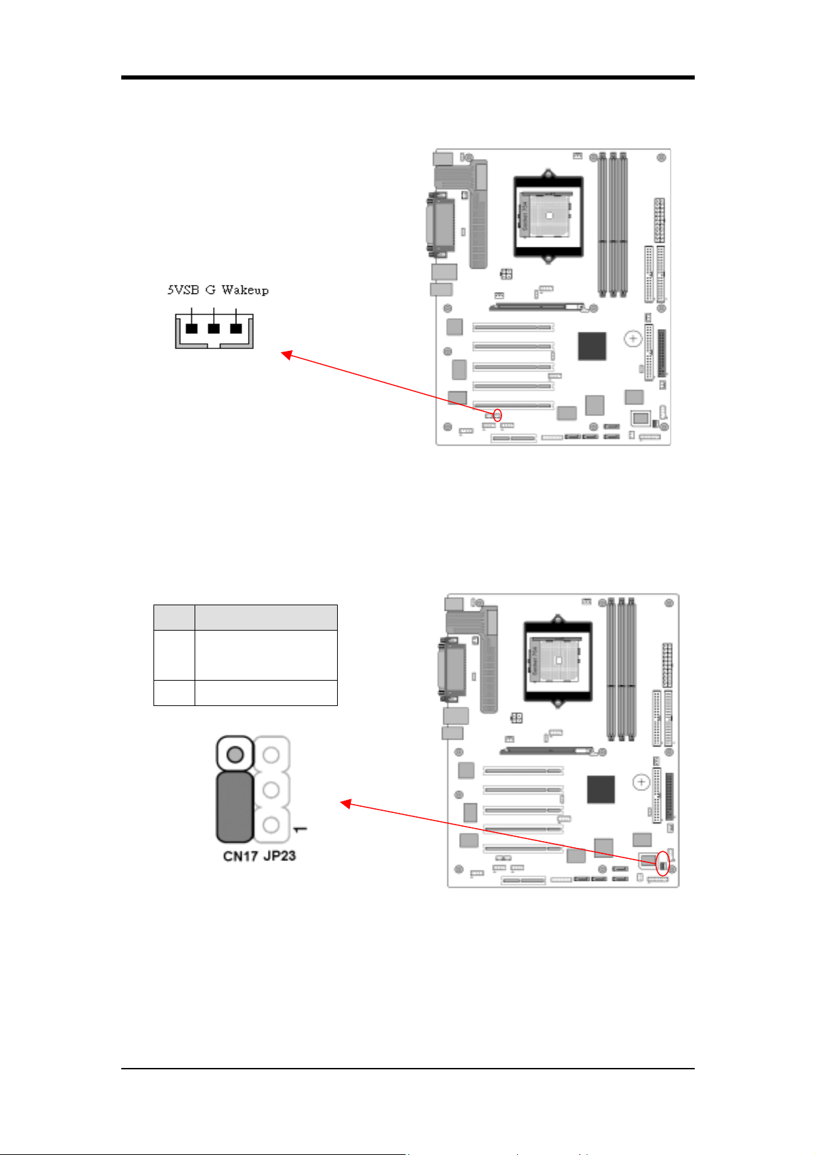
CN5A [WOM (Wake-on-Modem) Connector]:
Chapter 2
Enable the Wake Up On Modem selection in BIOS's Power Management Menu to
activate this function. This header is used to connect an add-in modem card, which
provides WOM function to the motherboard.
CN17 (Blue LED Connector)
Pin Definition
CHAINTECH
1-2
(default)
2-3 OEM
This feature works exactly the same as the power indicator LED, of which both
indicate the system’s power status. The only difference is that this one is blue while
the other one is red.
17
Page 26
Chapter 2
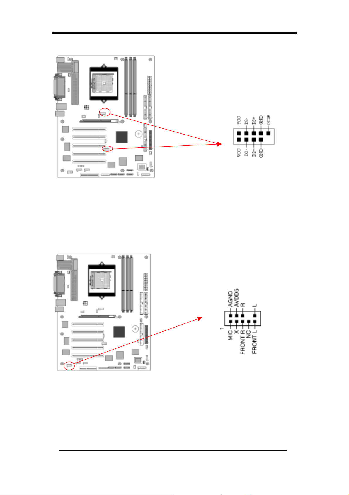
CN23 / 23C (USB Connector for USB 4/5 and 0/1):
USB Port 4/5 CN23 USB Port 0/1 CN23C
If you want to use a USB Keyboard, you must enable the USB keyboard support
function in BIOS's Integrated Peripherals menu (See Section 3.4). This board
contains a USB Host controller and a root hub with two connectors is also included
for an optional USB Adaptor (USB 0/1 and 4/5).
CN24 (CBOX™ 3 Front Audio Connector):
This connector gives you the option of a front-panel audio-jack cable ext. to be
plugged into a special custom-designed system case.
Simply remove the two jumper caps at pins [5-6] and [9-10] then plug it into the
(optional) cable ext. connector. Pins [5-6] and [9-10] are shorted (default) to enable
the back-panel audio function.
18
Page 27
Chapter 2
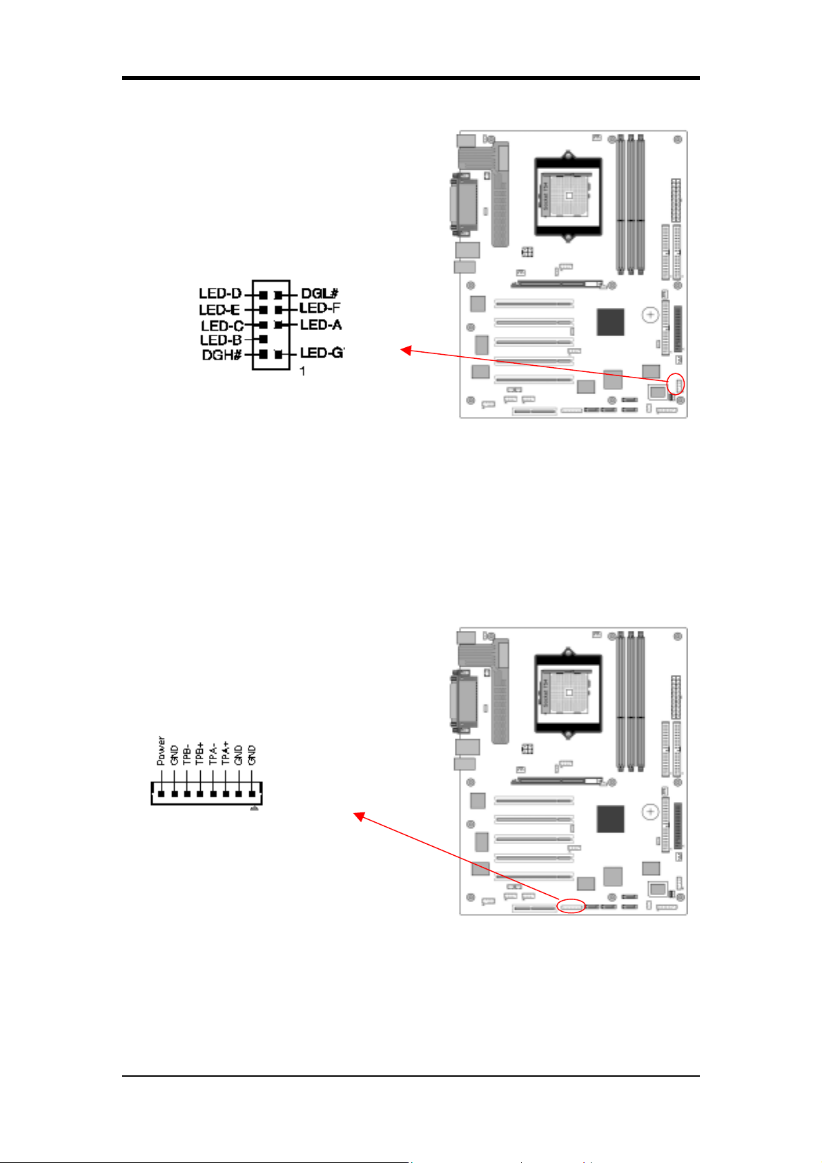
CN25 (CBOX™ 3 DigiDoc System Display Connector)
CHAINTECH’s exclusive DigiDoc, the most advanced system diagnostic
monitoring display came with the following functions:
- 80-PORT diagnostic display during POST at system boot up!
- CPU temperature monitoring, your system stays cool always!
- DigiDoc is the doctor for your system!
Refer to Appendix Digidoc 80-Port POST Error Code List for its details.
CN26 (IEEE 1394 Connector)
Attach the IEEE 1394 serial connector cable to the IEEE 1394 bracket, and the
CBOX™3 Front panel.
19
Page 28
Chapter 2
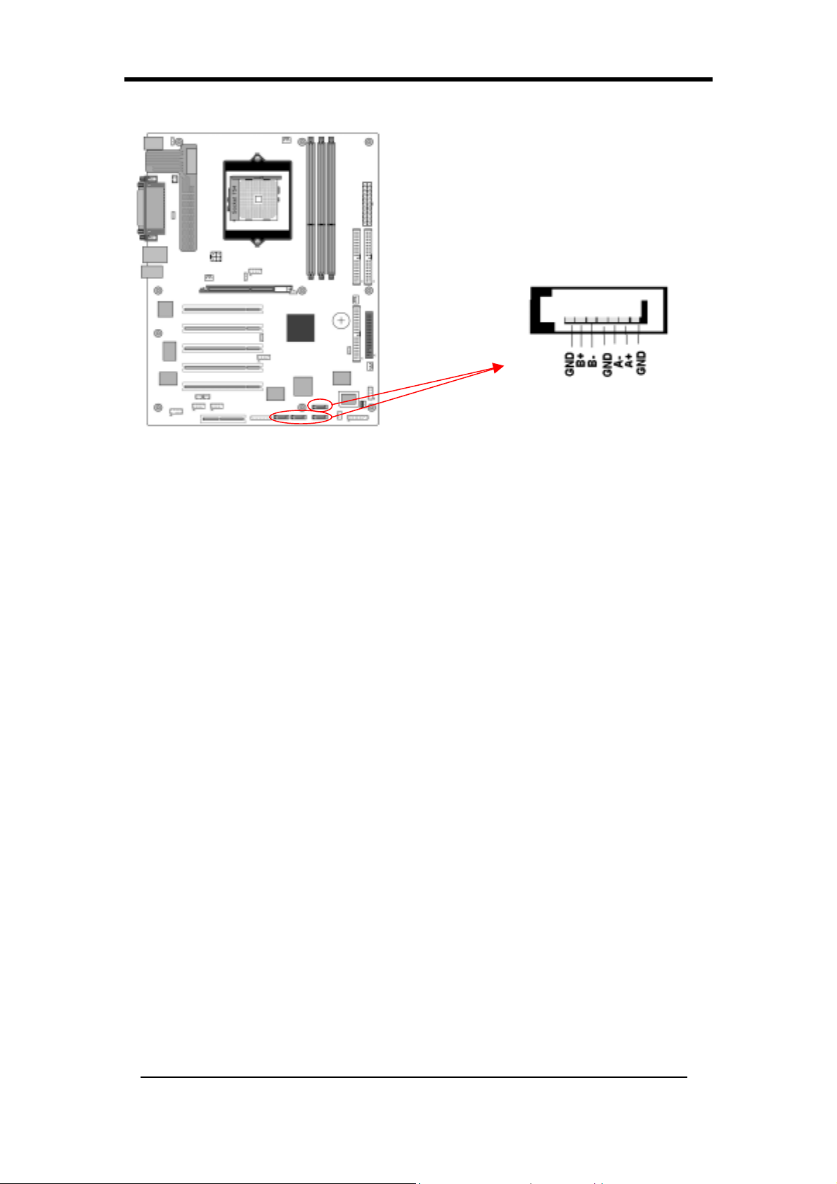
SATA 0/1/2/3 (Serial ATA Connector):
This can connect to new IDE device; it supports ATA 150MB/sec.
20
Page 29
Chapter 2
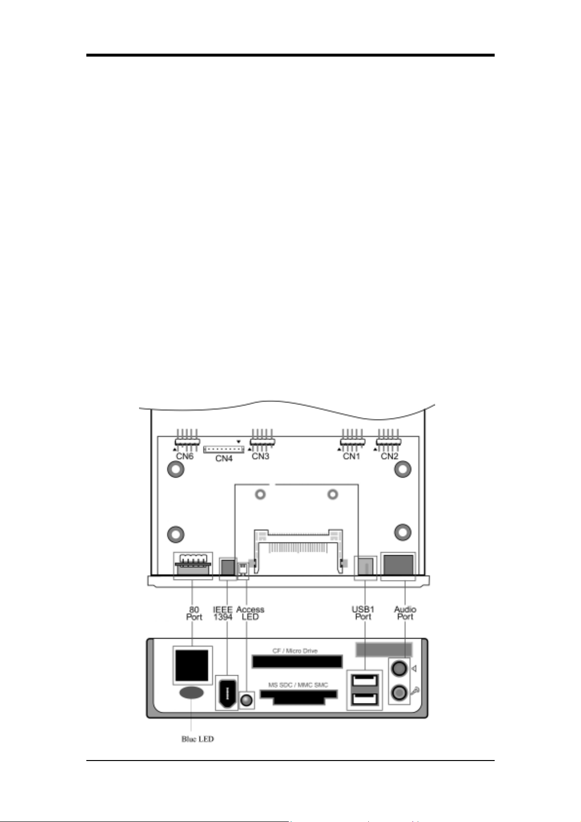
2-5 CBOX™ 3 Setup
1.
Gently insert CBOX™ 3 into the regular 5-1/4” drive bay at the front of
system chassis and securely tighten the side screws.
2.
Connect Motherboard to CBOX™ 3:
Function Motherboard CBOX™ 3
USB 4 & 5 CN23 CN1
USB 0 & 1 CN23C CN3
*Front Audio CN24 CN2
IEEE 1394 CN26 CN4
80 Port Display CN25 CN6
Note: For a proper installation of CBOX™ 3 please align the red edge of the Audio
and 80 port display cables with the arrows of CN2 and CN6 connectors respectively.
Remove CN24 Jumper Caps on motherboard 5-6, 9-10 before installation.
USB Cable (10 pin) x 2
Front Audio Cable (10 pin) x 1
IEEE-1394 Cable (8 pin) x 1
80 Port Cable (10 pin) x 1
21
Page 30
Chapter 2
It is NORMAL when error code “FF” is displayed on CBOX2/CBOX3
under any OS after the system has boot up. Only when APOGEE
Overclocking Utility or DigiDoc is properly installed and activated,
CBOX2/CBOX3 will show the current CPU temperature.
Please visit http://www.chaintech.com.tw for the newest versions of
APOGEE Overclocking Utility and DigiDoc.
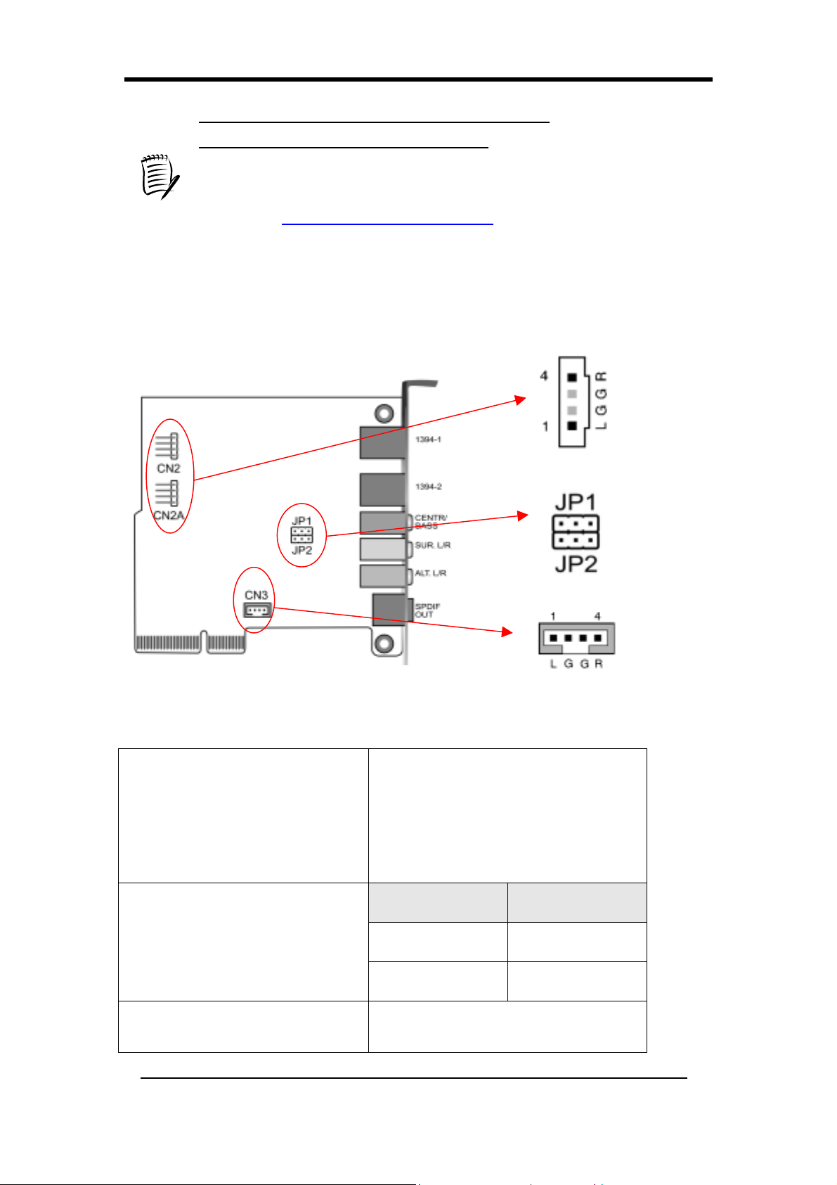
2-6 CMC (Chaintech Multimedia Card) Setup
CN2/CN2A
(CD-ROM Audio-in Connector)
JP1/JP2
(Bass/Center Select)
CN3(Auxiliary Audio-In
Connector)
22
Use the audio cable enclosed with
your CD-ROM disk drive to connect
the CD-ROM to your motherboard.
This will enable your CD-ROM's
audio function.
Pin Definition
1-2 Normal (Default)
2-3 Swap
This connector is for AUX Audio
Device.
Page 31
Chapter 2
硬體設定(Chinese)
即使您的主機板己經安裝於電腦中,當您打算升級您的電腦配備時,您可能還
是需要參考此章節。
在做任何硬體安裝前,請務必拔除電源線,並穿戴應有的保護措施,以免電源
衝擊損壞設備!
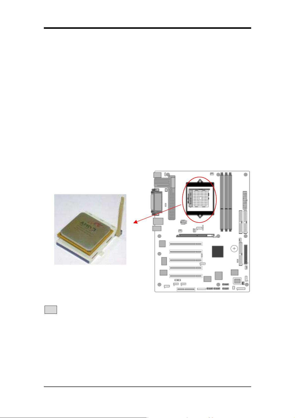
2-7 安裝 CPU 在 Socket 754
Socket 754,可安裝 AMD Athlon 64 的 CPU。以下是將 CPU 安裝於 Socket 754
的詳細介紹:
1. 將CPU朝上(如圖),並且找出 CPU 缺角。
2. 拉開Socket 754基座旁的拉捍,使其垂直於主機板。輕輕地將CPU嵌入於
Socket 754,使缺角互相對應,然後合上拉桿。(請勿重壓CPU,這樣對CPU
有害)
3. 請安裝AMD認可的散熱器,否則會因過熱而燒毀CPU。
注意:安裝 CPU 前,請先將電源關閉。
23
Page 32
Chapter 2
2-8 CPU Jumper 設定
頻率設定
頻率由 CPU 自動控制。
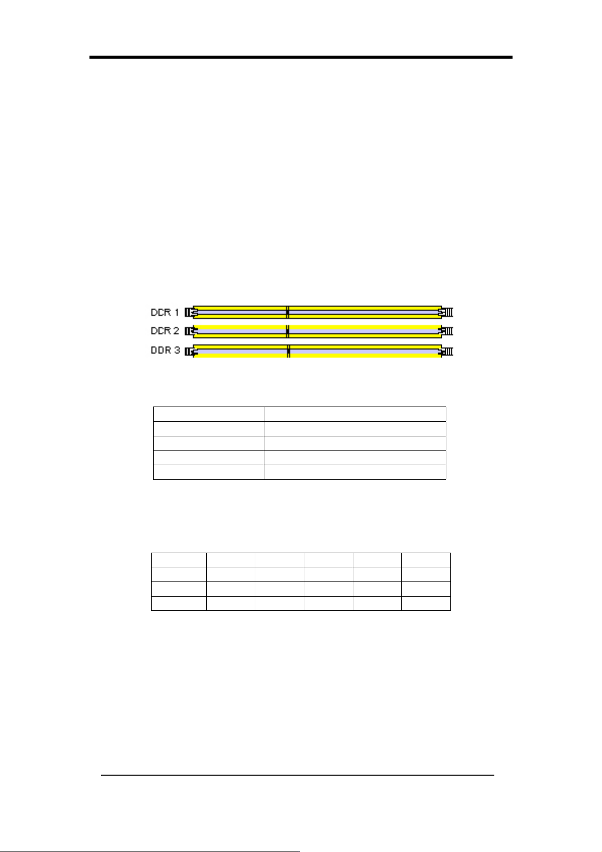
2-9 記憶體的配置
DDR SDRAM 由 3 根插槽組成。第一根插槽可支援最大容量 1GB 的
記憶體,而第二和第三根插槽一起可支援最大容量 1 GB 的記憶體。若
第二與第三插槽同時使用,只能支援單面記憶體模組。若三個插槽同時
使用,插槽一(雙面),插槽二(單面),插槽三(單面) 只能支援到 DDR333。
關於 DDR SDRAM 相容性表格請參考附錄。
DDR SDRAM 的 敍 述
Memory Frequency Internal System BUS Frequency
100 MHz 200 MHz
133 MHz 266 MHz
166 MHz 333 MHz
200 MHz 400 MHz
記憶體插槽類型:2.5V, 184 pin 64/128/256/512-bit DDR SDRAM
記憶體模組容量:單邊/雙邊 64/128/256/512MB/1GB
相容性 :同一類型或是不同類型皆可
Location 64 MB 128 MB 256 MB 512 MB 1.0 GB
DDR 1 V V V V V
DDR 2 V V V V V
DDR 3 V V V V V
關於可支援的 DDR SDRAM 表格請參考附錄。
24
Page 33
Chapter 2
2-10 連接座和Jumper設定
連接座的用途為連接主機板和系統的其他部份,包括電源、鍵盤和機殼面板上
的控制器。
當安裝主機板時,電源供應器之連接座,要安排最後再接上。而且在連接
前,請確定電源供應器的電源,並未接上電,以確保安全。
所有的連接線已通過承啟安全認證。
PW 1 / 3 (ATX 電源連接座)
在系統組裝過程中,最後一個步驟才能將 PW1/3 與外部
電源接上。AT X 電源供應器,提供一組 20 個腳位的連
接介面,其中包含了標準+/-5V,+/-12V,額外的 3.3V 和
電源信號。此信號是一個 5V 微量電源,當主電源被接
上以後,即可連續供電。當系統處於軟體關機摸式時,
此微量電源將可維持系統處於最小的電源供應狀態。
ATX 12V 電源供應器支援新的+12V (4 個腳位) 和
+5V/3.3V (6 個腳位)輔助電源接頭,可提供更多的 +12
V 與+5/3.3V 電源到主機板上。
數據機啟動控制
當系統處於軟體關機摸式時,若數據機偵測到外部傳來的
振鈴信號,系統將自動啟動,並可從遠端遙控使用。若要
使用此功能,須於 BIOS 的 Power Management Setup 設定
選單中啟用此功能 (參考 3-18 章節)。
暫停模式之閃爍 LED 功能
當進入暫停模式時,您電腦面板上的 LED 燈將閃爍,只要您按下外殼上的省電
按鈕,或將 BIOS 的 Power Management menu 下之 Suspend Mode 選項啟動,則
可進入暫停模式 (參考 3-18 章節)。
Poly-fuse 過電流保護
此保險絲用來保護經由鍵盤或 USB 接頭傳來的危險電壓,可快速地切斷電路,
並在一段時間後,於安全狀態下回復正常使用狀態,不像一般的保險絲燒毀後
就必須更換。
25
Page 34
Chapter 2
CN1A (前置面板控制接頭)
1.
PWR-SW (Over-ride 電源按鈕接頭)
AT X 機殼上的電源按鈕,可用來當做普通的電
源開關,也可以用來使系統進入 ”電源管理系
統” 模式。這個模式可在當電腦有一段長時間
不使用時,做節省電源的設定。若要使用此功
能,請在 BIOS 的電源管理選項中,將 Soft-off
by PBTN 設定為[Delay 4 Sec.]。
當 Soft-off by PBTN 功能被啓用後,若快速的
按一下電源開關,將使系統進入省電模式。若
此時外部有任何動作,例如:按鍵盤上的任一鍵或是移動滑鼠,則會使系
統回復到完全開機模式。如果在完全開機模式下,按下電腦機殼前的電源
超過 4 秒,則系統將會完全關機。
2.
P-LED(電源 LED 燈接頭)
此 LED 顯示系統的電源狀態。請確認您的連接線是否插入正確的腳座。
(若沒有時只要將連接線對調即可)。
3. G-BTN (綠色開關接頭)
有些 AT X 外殼提供省電開關,讓系統能進入暫停模式。在暫停模式下,
供應系統之電源將降低至微電源,且 CPU 的時脈停止,而 CPU 的核心
將處在最小電源狀態,當按下鍵盤或移動滑鼠時,系統將自動甦醒。系統
甦醒後的運作模式有很多種,可以在 BIOS 的電源管理設定中設定。
4.
RESET (系統重置開關接頭)
用來連接機殼前方面板上重置開關,按此開關將可在不關閉電源之下,重
新開機,重新啟動系統。
5. SPEAKER(喇叭連接座)
4 腳位的接頭,用來連接系統喇叭。
6. HD-LED(IDE 動作 LED 指示燈接頭)
用來連接機殼前方面板上之 IDE 動作指示燈,當 IDE 裝置動作時,此指
示燈會閃爍。
FD1 (軟碟機連接座)
此主機板提供標準的軟碟機連接頭,可支援 360K, 720K, 1.2M,
1.44M 和 2.88M 類型的軟碟機。使用這連接頭,須連接 34 腳座
的軟碟機。
26
Page 35
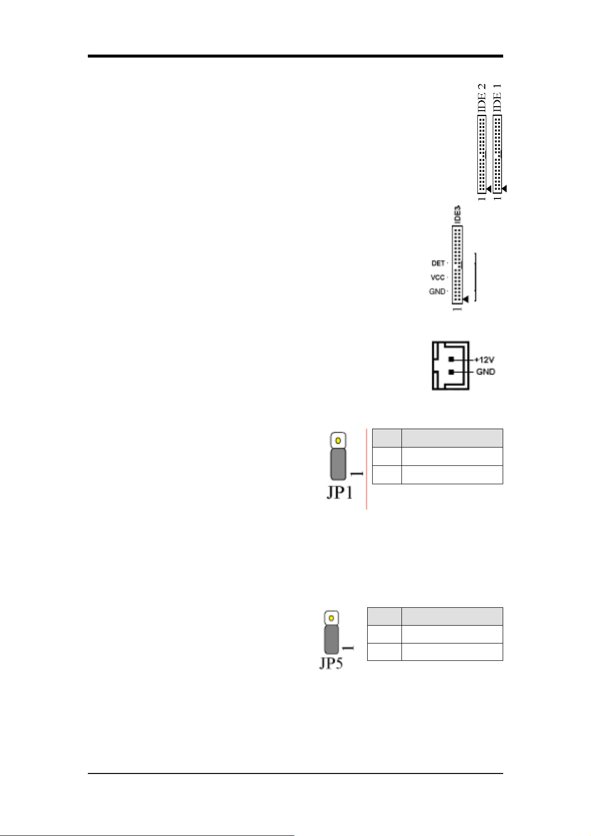
IDE 1/2/3 (IDE 硬碟機連接座)
此主機板有 32-bit PCI IDE 和 Ultra ATA66/100 連接座,可提供 PIO
mode 0~4Bus Master 和 ultra DMA AT66/100/133 的功能。此連接頭用於
連接 40 腳座的設備。
IDE 1 只能連接 2 個 IDE 設備 (Primary Master/Slave)。
IDE 2 只能連接 2 個 IDE 設備 (Secondary Master/Slave)。
IDE 3 只能連接 2 個 IDE 設備 (Tertiary Master/Slave)。
FAN1/2/3/4 (CPU/系統/機殼/北橋風扇接頭)
這些接頭可讓風扇從主機板上得到電源。主機板的
硬體管理系統可以偵測 CPU/系統風扇的轉速。 一般標準的風
扇,紅色是正極(+12V), 黑色是接地線的,黃色則是轉速
訊號線。連接北橋的是 FAN4。
Chapter 2
FAN 5 (Heat-Pipe Connector)
RadEX 風扇的專屬連接座。
JP1(清除 CMOS 資料)
依下列步驟清除 CMOS 資料:
1.
拔掉電源線。
2.
將 jumper 插在[2-3]腳位,約
<5 秒>後, 再插回預設位置。
3.
接上電源並開機。
4.
進入 BIOS 設定中,選擇 ”Load Optimized Defaults”,按[Y] 之後再按
[Enter]。
5.
在 Standard CMOS Setup 下 選擇設定系統的正確參數。
JP5 (鍵盤開機功能)
此功能可讓使用者以 PS/2 介面的鍵盤開
Pin Definition
1-2 Normal (default)
2-3 Clear CMOS Data
Pin Definition
1-2 Disable (default)
機 (設定快速鍵)。在 BIOS 設定中的 ”
2-3 Enable
Power Management Setup” 選單中選擇 ”
Wake Up Events”,在 ”HOT Key Power
ON” 選項中設定鍵盤開機快速鍵。必須將 jumper 調至[2-3]腳位方可使用。
27
Page 36
Chapter 2
JP6 (USB 2/3 USB 裝置開機功能)
此功能讓您可使用主機板上的 USB 的鍵
盤或是滑鼠,來喚醒您的電腦。但您須在
BIOS 的 ” Power Management Setup”下做
相關設定,並且須將 jumper 調至[2-3] 腳
位才可使用這個功能。
JP 6A / 6D (USB 4/5,0/1 裝置開機功能)
JP6A -> USB 4/5, JP6D -> USB 0/1
此功能讓您可使用主機板上的 USB 的鍵
盤或是滑鼠,來喚醒您的電腦。但您須在
BIOS 的 ” Power Management Setup”下設
定,並且您須將 jumper 插在 [2-3] 腳位
才可使用這個功能。
JP23 (綠色指示燈接頭)
設定綠色指示燈(Green LED)
Pin Definition
1-2 Disable (default)
2-3 Enable
Pin Definition
1-2 Disable (default)
2-3 Enable
Pin Definition
CHAINTECH
1-2
(default)
2-3 OEM
JP25 (ROM Table Select ): Optional
在開機時,當 jumper 設在【1-2】腳位時,
是使用者模式。 若 jumper 設在【2-3】腳
位時,是安全模式。
Pin Definition
1-2 User Mode
2-3 Safe Mode
CN5 (網路喚醒系統 Wake-on-LAN 接頭)
在 BIOS 的” Power Management Setup” 中將”Wake up on
LAN” 選項設定為 enable 以啟動此功能。這個接頭是用來連
接支援 Wake-on-LAN 的網路介面卡 (Network Interface
Card) ,提供主機板網路喚醒功能。
CN5A (網路撥接喚醒系統(Wake-on-Modem)接頭)
在 BIOS 的” Power Management” 中設定以使用這個功能。
這個接頭是用來連接網路撥接介面卡,而介面卡須支援
Wake-on-Modem,才能提供主機板網路撥接喚醒功能。
28
Page 37
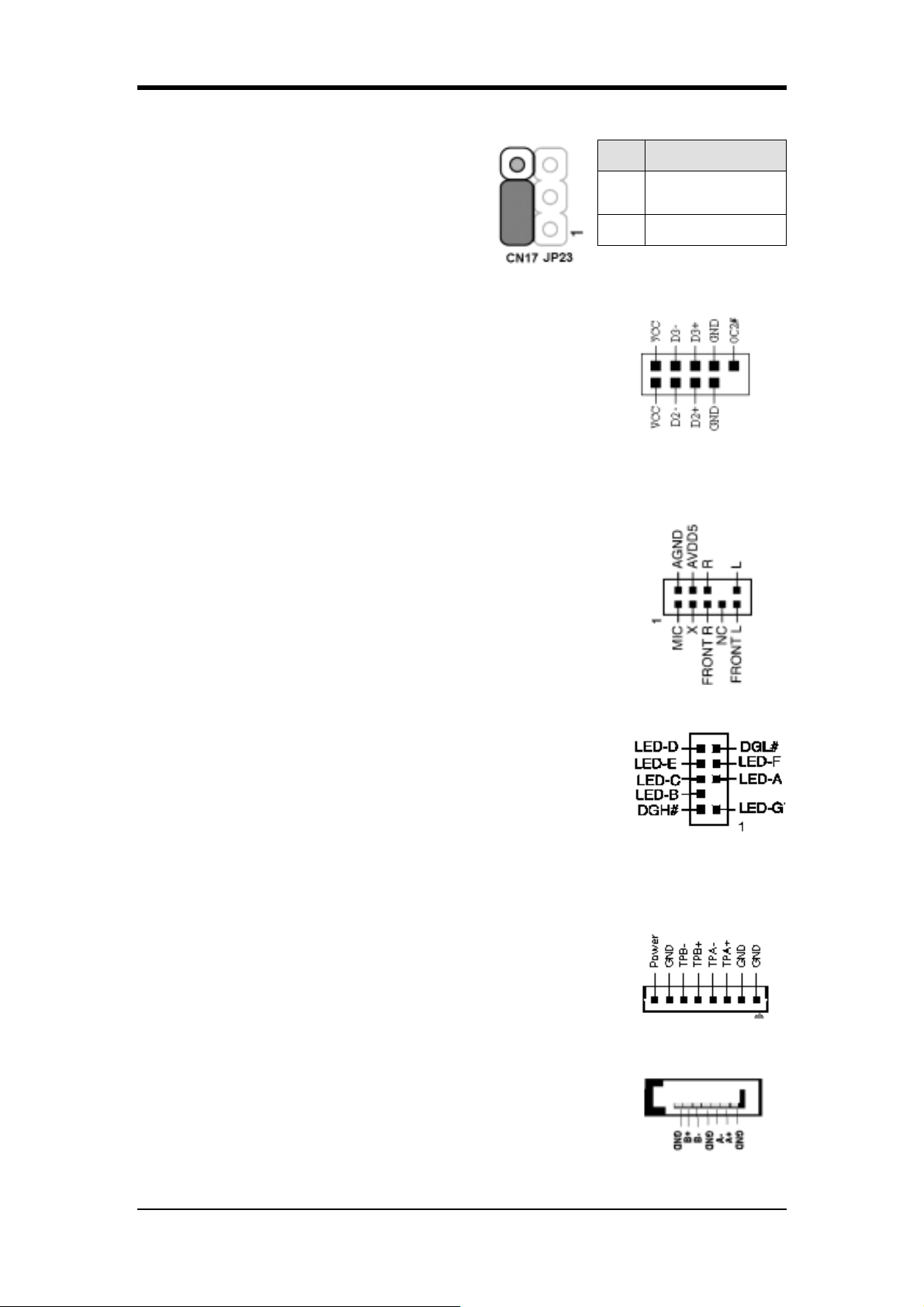
CN17 (藍色指示燈接頭)
Chapter 2
此功能跟電源指示燈一樣,可顯示系統電
源狀況。唯一不同點是一個爲藍色,另一
個爲紅色。
CN23/CN23C (USB 4/5 和 0/1)
USB Port 4/5 CN23 , USB Port 0/1 CN23C
假如您要使用 USB 接頭的鍵盤,您要在 BIOS 的 ”
Integrated Peripherals”中 選擇”ENABLE” (參考 3-17 章
節)。這個主機板有一 USB 中心控制器和一個中心集線
器,這個功能可讓您接兩個 USB 的設備,另一個也可以接
出兩個 USB 的設備,共 4 個 USB 的設備 (USB 0/1 和
4/5)。
CN24 (CBOX ™ 3 音效接頭)
這接頭讓您可選擇使用前置面板音效。
Pin Definition
1-2
CHAINTECH
(default)
2-3 OEM
拔除 jumper 帽蓋 [5-6] 和 [9-10],然後接上排線。
CN25 (CBOX™ 3 DigiDoc 數位醫生 80-Port 顯示器接頭)
[DigiDoc]數位醫生是 CHAINTECH 獨家CBOX3 的特色之
一。功能如下:
1. 可在開機期間顯示系統錯誤診斷碼。
2. 安裝DigiDoc 軟體後,在作業系統下可顯示 CPU 溫
度和風扇的轉速!
Digidoc 80-Port 錯誤診斷碼說明,請參考附錄及 CBOX 內盒所附貼紙。
CN26 (IEEE 1394 接頭)
連接 IEEE 1394 連接線到
CBOX™3 前置面板。
SATA 0/1/2/3 (Serial ATA Connector)
連接新型的 Serial ATA 硬碟, 支援 ATA
150MB/sec。
29
Page 38
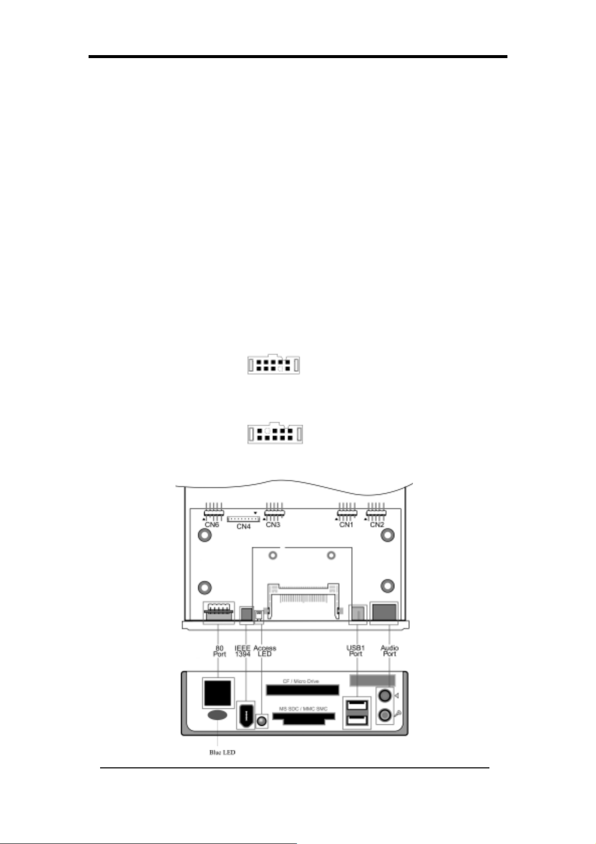
Chapter 2
2-11 CBOX™ 3 設定
1. 輕輕地嵌入 CBOX™ 3 到標準的 5-1/4 機殼前面板插槽裏,而且栓緊螺絲。
2. 連接主機板和 CBOX™ 3 的接頭:
功能 主機板
CBOX™ 3
USB 4 & 5 CN23 CN1
USB 0 & 1 CN23C CN3
*前置音效
CN24 CN2
IEEE 1394 CN26 CN4
80 Port Display CN25 CN6
NOTE : CBOX3 的音效和 80 PORT 的正確安裝----請將音效和80 PORT 的
排線的紅邊靠同一邊, 分別插在 CBOX3 的 CN2 和 CN6 的連接頭上,
即可使用.
* 在安裝前,先移動主機板 CN24 Jumper [5-6],[9-10]帽蓋
USB 排線 (10 pin) x 2
前置音效排線(10 pin) x 1(接頭圖示如下,防呆塞孔在下排)
IEEE-1394 排線(8 pin) x 1
80 Port 排線(10 pin) x 1(接頭圖示如下,防呆塞孔在上排)
* 安裝時請將塞孔對準 CBOX3 上腳座缺針位置
30
Page 39
Chapter 2
開機進入作業系統後, 當"FF"字樣顯示在CBOX2/CBOX3 的螢幕時, 這代
表系統運作正常.
當 APOGEE 超頻軟體或 DigiDoc 監控軟體已正確安裝在系統時, 在
CBOX2/CBOX3 的螢幕上, 將會顯示 CPU 當時的工作溫度.
請到 http://www.chaintech.com.tw.下載最新的 APOGEE 超頻軟體或
DigiDoc 監控軟體
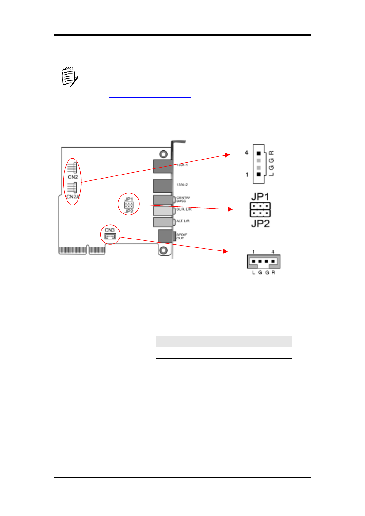
2-12 CMC (Chaintech多媒體卡) 設定
CN2/CN2A
(光碟機音效輸入接頭)
JP1/JP2
(Bass/Center Select)
CN3
(外加音效輸入接頭)
利用光碟機所附之音源線,將光碟機連接
到主機板上,將可啟動光碟機音效功能
Pin Definition
1-2 Normal (Default)
2-3 Swap
外加音效輸入接頭
31
Page 40
Chapter 2
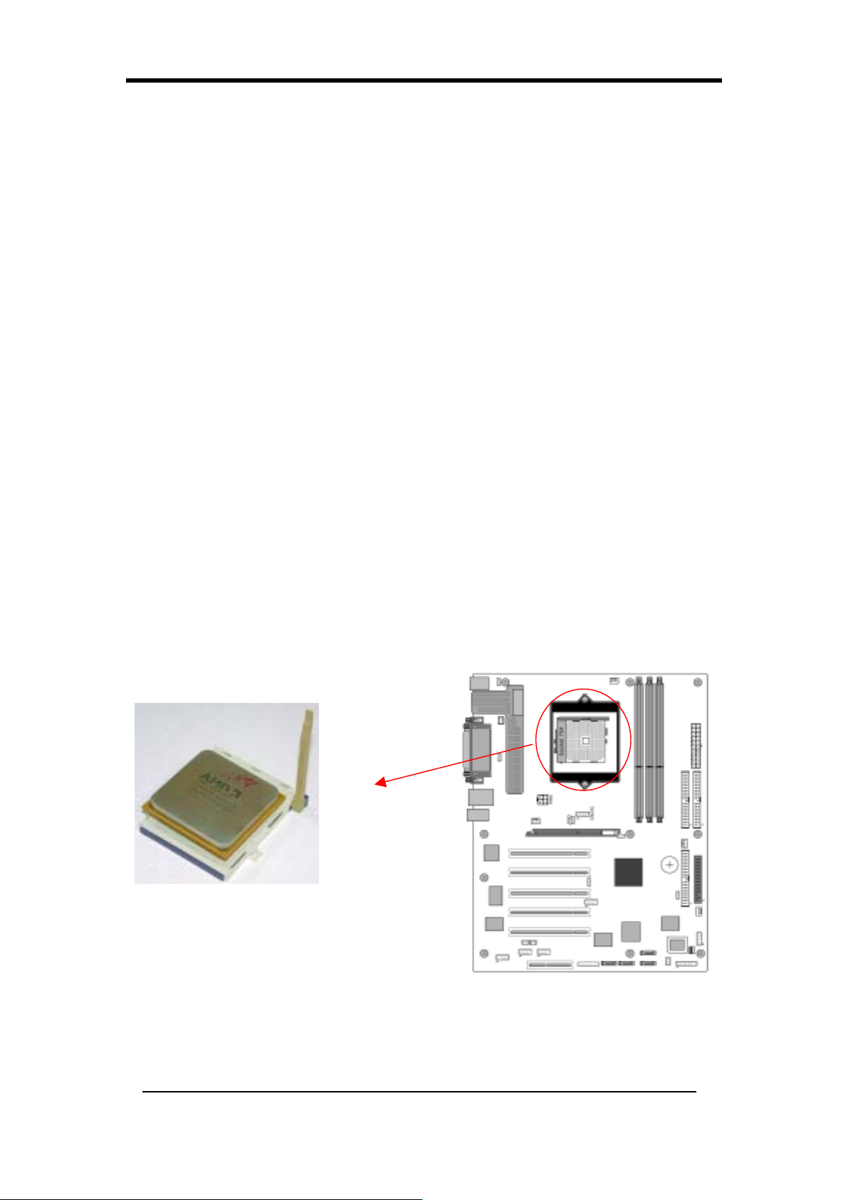
Installation Matérielle (French)
Si votre carte mère a déjà été installée dans votre ordinateur ce chapitre peut quand
même vous être utile si vous prévoyez de mettre à niveau le matériel de votre système.
Cette carte mère est sensible à l’électricité statique. Ne la touchez pas sans porter un
équipement adéquat et prenez soin de déconnecter le câble d’alimentation de la source
de courant avant d’entreprendre quoi que ce soit sur la carte mère. Le non respect de
ces consignes vous expose à des risques d’électrocution !
2-13 Installation d’un Processeur CPU dans le Socket 754
Le Socket 754, conçu pour les processeurs AMD Athlon 64, a été incorporé comme une
spécification standard de carte mère. Pour insérer votre CPU dans le Socket 754 veuillez
procéder comme suit :
1
. Repérez un pan coupé à la surface du CPU, se trouvant à proximité d’un des angles
du CPU. Le même angle sera aussi tronqué, laissant une encoche reconnaissable
dans l’angle du CPU. Ces marques indiquent la Broche 1 sur le CPU.
2. Soulevez le levier du Socket 754 de sorte qu’il soit perpendiculaire à la surface de la
carte mère. Insérez doucement le CPU avec la Broche 1 dans le même angle du
Socket 754, qui est situé à proximité de l’extrémité du levier. Laissez le CPU se
mettre en place de lui même par son poids. N’appliquez pas de pression
supplémentaire car cela pourrait endommager votre CPU. Raccrochez le levier à sa
place.
Il est nécessaire d’installer un dissipateur de chaleur approuvé AMD avec un
ventilateur pour une dissipation de chaleur correcte de votre CPU. Si vous
n’installez pas ces éléments cela peut entraîner une surchauffe et risque de griller
votre CPU.
Remarques: Pour démarrer avec un CPU nouvellement installé, L’alimentation
doit être mise hors tension avant l’installation.
32
Page 41
Chapter 2
2-14 Configuration des Cavaliers du CPU
Configuration de la Fréquence :
Cette fréquence est automatiquement ajustée par le CPU.
2-15 Configuration de la Mémoire Principale
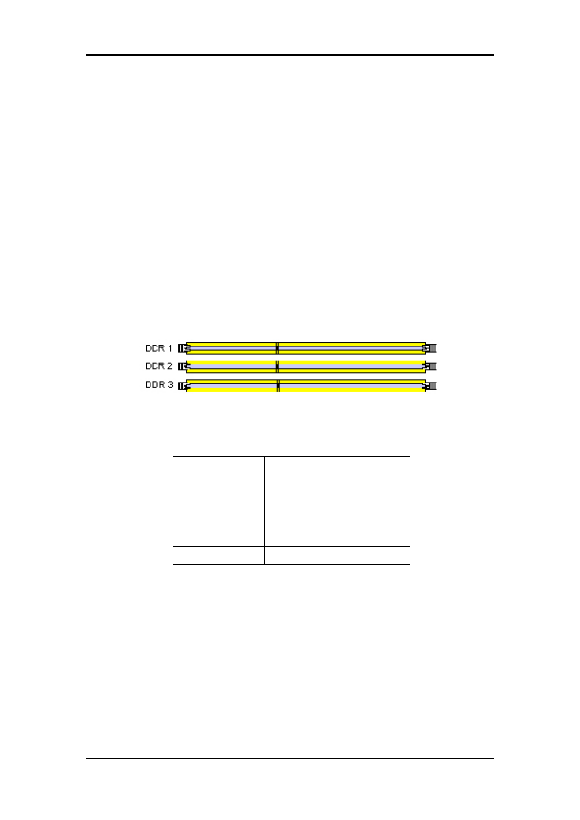
Le système mémoire DDR SDRAM est composé de 3 banques. La premières
banque supporte jusqu’à 1GB de mémoire, la deuxième et la troisième ne supportent
ensemble que jusqu’à 1GB de mémoire total. Nous vous suggérons fortement
d’installer les barrettes mémoires dans les slots DIMM1 + DIMM2 ou DIMM1
+DIMM3. Une installation des mémoires en DIMM2 + DIMM3 n’est pas
recommandée puisqu’elle pourrait entraîner une instabilité du système.
Merci de vous référez à l’Appendice (anglais) pour la table de compatibilité
mémoire.
Spécifications de la SDRAM DDR
Fréquence de
Mémoire
Fréquence de BUS de
Système Interne
100 MHz 200 MHz
133 MHz 266 MHz
166 MHz 333 MHz
200 MHz 400 MHz
Type de DIMM : SDRAM DDR 2.5V, sans mémoire tampon de 184 broches
64/128/256/512 bits
Taille du module :Simple/double face 64/128/256/512Mo/1Go
Parité : Soit parité ou non parité
Merci de vous référez à l’Appendice pour des informations détaillées sur le Support
des mémoires DDR DRAM.
33
Page 42
Chapter 2
Emplacement 64 Mo 128 Mo 256 Mo 512 Mo 1.0 Go
DDR 1 X X X X X
DDR 2
X
X X X X
DDR 3 X X X X X
2-16 Paramètres de Connecteurs et de Cavaliers
Les connecteurs sont utilisés pour relier la carte système aux autres parties du
système, y compris l’alimentation, le clavier, et les divers contrôleurs situés sur le
panneau avant du boîtier du système.
Le connecteur d’alimentation est la dernière connexion à réaliser lors de
l’installation de la carte mère. Avant de connecter le boîtier
d’alimentation, assurez-vous qu’il n’est pas connecté à la source
d’alimentation.
Tous les câbles fournis par CHAINTECH sont sécurisés.
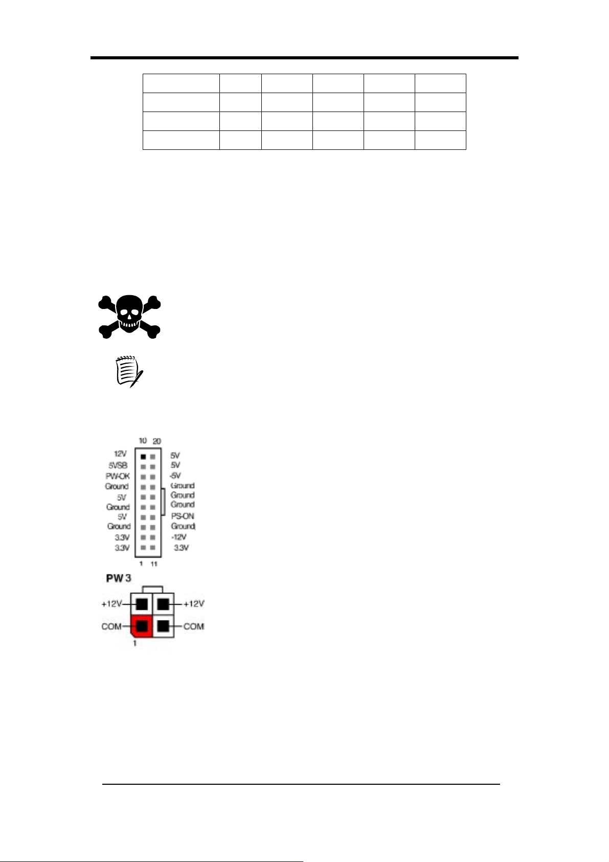
PW 1/3 (Connecteur d’Alimentation ATX):
Le cordon d’alimentation reliant l’alimentation du système à
la source d’alimentation externe doit être la toute dernière
partie connectée quand vous assemblez un PC.
L’alimentation ATX fournit un connecteur d’interface
unique à 20 broches, intégrant les signaux +/-5V, +/-12V
standards, 3.3V optionnel et Soft-power. Le signal
Soft-power, un courant d’alimentation d’entretient de 5V est
fourni en continu quand l’alimentation secteur est disponible.
Quand le système est en mode Soft-Off, cette alimentation
d’entretien maintient le système à son état d’alimentation
minimum.
L’alimentation ATX 12V possède un nouveau connecteur
d’alimentation auxiliaire en +12V (4 broches) et +5V /
3.3V (6 broches) pour permettre de délivrer un courant de plus de +12 VDC et + 5/
3.3V VDC à la carte mère.
Mise sous Tension Par Modem :
En état Soft-Off, si un signal de sonnerie de modem externe est détecté, le système
sera activé et on peut donc y accéder à distance. Vous pouvez activer cette fonction
dans le menu Setup de Gestion d’Alimentation du BIOS. (Voir section 3-31)
34
Page 43
Chapter 2
LED Clignotante en Mode Suspension :
Lorsque vous êtes en mode Suspension, le voyant LED situé sur le panneau avant de
votre ordinateur se mettra à clignoter. Vous pouvez entrer en mode Suspension en
appuyant sur Bouton d’allumage de votre boîtier ATX, ou en activant les options de
Gestion d’Alimentation et de Mode de Suspension dans le menu de Gestion
d’Alimentation du BIOS. (Voir section 3-31)
Protection contre les Surtensions par Fusible Autoréarmable :
Le fusible autoréarmable protège le système contre les voltages dangereux auxquels
le système risque d’être exposé via le clavier ou les connecteurs USB. En cas d’une
telle exposition, le fusible autoréarmable sera immédiatement déconnecté du circuit,
simplement comme un fusible normal. Après avoir été déconnecté pendant une
certaine durée, le fusible autoréarmable retournera à son état normal et le clavier ou le
connecteur USB pourra fonctionner à nouveau correctement. Contrairement aux
fusibles conventionnels, il ne sera pas nécessaire de remplacer le fusible
autoréarmable, libérant l’utilisateur de tels désagréments.
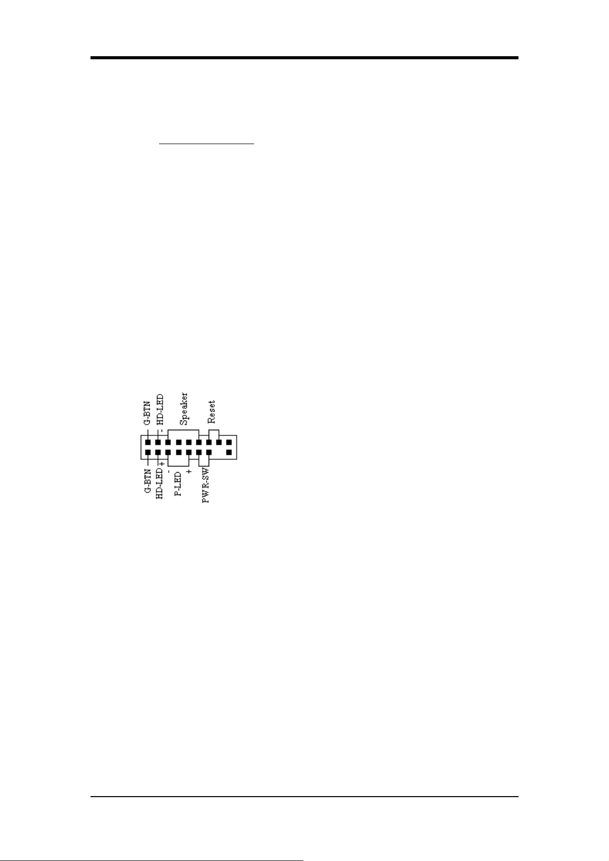
CNIA (Connecteur de Face Avant) :
1. PWR-SW (Connecteur de Bouton d’Alimentation):
Le bouton d’alimentation du châssis ATX peut
être utilisé comme un commutateur
d’alimentation normal ainsi que comme un
dispositif destiné à activer le mode de Suspension
de Gestion d’Alimentation. Ce mode d’économie
d’énergie est utilisé pour économiser de
l’électricité quand l’ordinateur n’est pas utilisé
pendant une période prolongée. La fonction “ Soft-OFF by PWR-BTTN”
dans le menu Setup de Gestion d’Alimentation du BIOS doit être
positionnée sur [Delay 4 Sec.] pour activer cette fonction.
Quand la fonction “Soft-OFF by PWR-BTTN” est activée, le fait d’appuyer
rapidement sur le bouton d’alimentation commutera le système en mode
Suspension. Toute occurrence d’activités externe telle que le fait d’appuyer
sur une touche du clavier ou de déplacer la souris ramènera le système en
“Full-On”. Le fait d’appuyer sur le bouton pendant au moins [4 secondes]
quand vous êtes en mode “Full-On” éteindra complètement le système. Voir
le schéma de Fonctionnement du Bouton d’Alimentation.
2. P-LED (Connecteur de LED d’Alimentation):
Le voyant LED d’alimentation affiche l’état d’alimentation du système. Il est
important de prêter attention aux câbles et à l’orientation correctes des broches
(c.-à-d., faites attention à ne pas inverser l’ordre de ces deux connecteurs.)
35
Page 44
Chapter 2
3. G-BTN (Connecteur de Bouton d’Alimentation):
Certains boîtiers ATX offrent un commutateur Vert, utilisé pour mettre le système
en mode Suspension. En mode Suspension, l’alimentation du système est réduite à
un courant d’entretien, l’horloge du CPU est arrêtée, et le noyau du CPU est à son
d’état d’alimentation minimum. Le système est activé quand vous touchez au
clavier ou à la souris. Le système reprendra de différentes façons comme défini par
l’écran de Paramétrage de Gestion d’ Alimentation du BIOS.
4. RESET (Connecteur de Réinitialisation du Système):
Ce connecteur doit être connecté au commutateur de réinitialisation situé sur le
panneau avant du boîtier système. Le commutateur de réinitialisation vous permet de
redémarrer le système sans éteindre le système.
5. SPEAKER (Connecteur de Haut-parleur):
Ce connecteur à 4 broches se connecte aux haut-parleurs montés sur le boîtier.
6. HD-LED (Connecteur LED d’Activité IDE):
La LED d’activité IDE s’allume chaque fois que le système lit/écrit sur les
périphériques IDE.
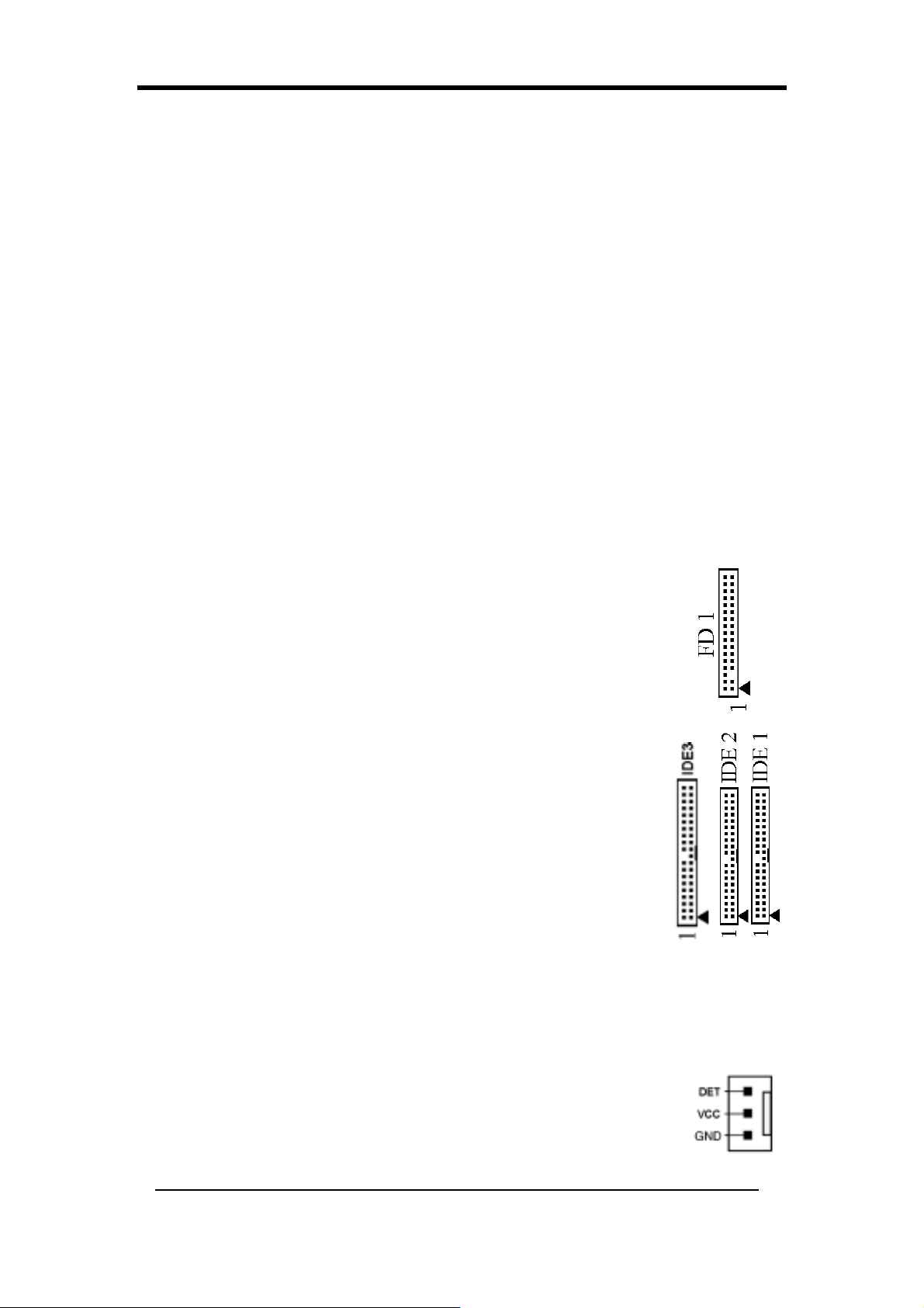
FD1 (Connecteur de Lecteur de Disquette) :
La carte mère offre un connecteur de lecteur de disquette standard
supportant les types de disquettes de 360K, 720K, 1.2M, 1.44M et
2.88Mo. Un lecteur de disquette de 34 broches est connecté à l’aide de
ce connecteur.
IDE 1/2/3 (Connecteur de Disque Dur IDE) :
La carte mère possède un contrôleur IDE PCE Amélioré de 32 bits
et Ultra ATA66/100 offrant le mode PIO 0~4, Maîtrise de Bus, et la
fonction Ultra ATA66/100. Ce connecteur est utilisé pour
connecter des périphériques ATAPI à 40 broches.
IDE 1 se connecte seulement à deux périphériques IDE.
(Maître/Esclave Principal)
IDE 2 se connecte seulement à deux périphériques IDE.
(Maître/Esclave Secondaire)
IDE 3 se connecte seulement à deux périphériques IDE. (Maître/Esclave Tertiaire)
FAN1/2/3/4 (Connecteurs de Ventilateur de Refroidissement du
CPU/Système/ Case Fan/ Chip Fan):
Le gestionnaire de matériel de la carte peut détecter la vitesse de
rotation du ventilateur du CPU et du système en t/mn (tours par
minute). Le câblage et les connexions peuvent varier en fonction du
36
Page 45
Chapter 2
fabricant. Sur les ventilateurs standard, le fil rouge est le positif (+12V), le noir est la
masse, et le fil jaune est le signal de rotation. Connectez le ventilateur de
refroidissement north-bridge sur FAN4.
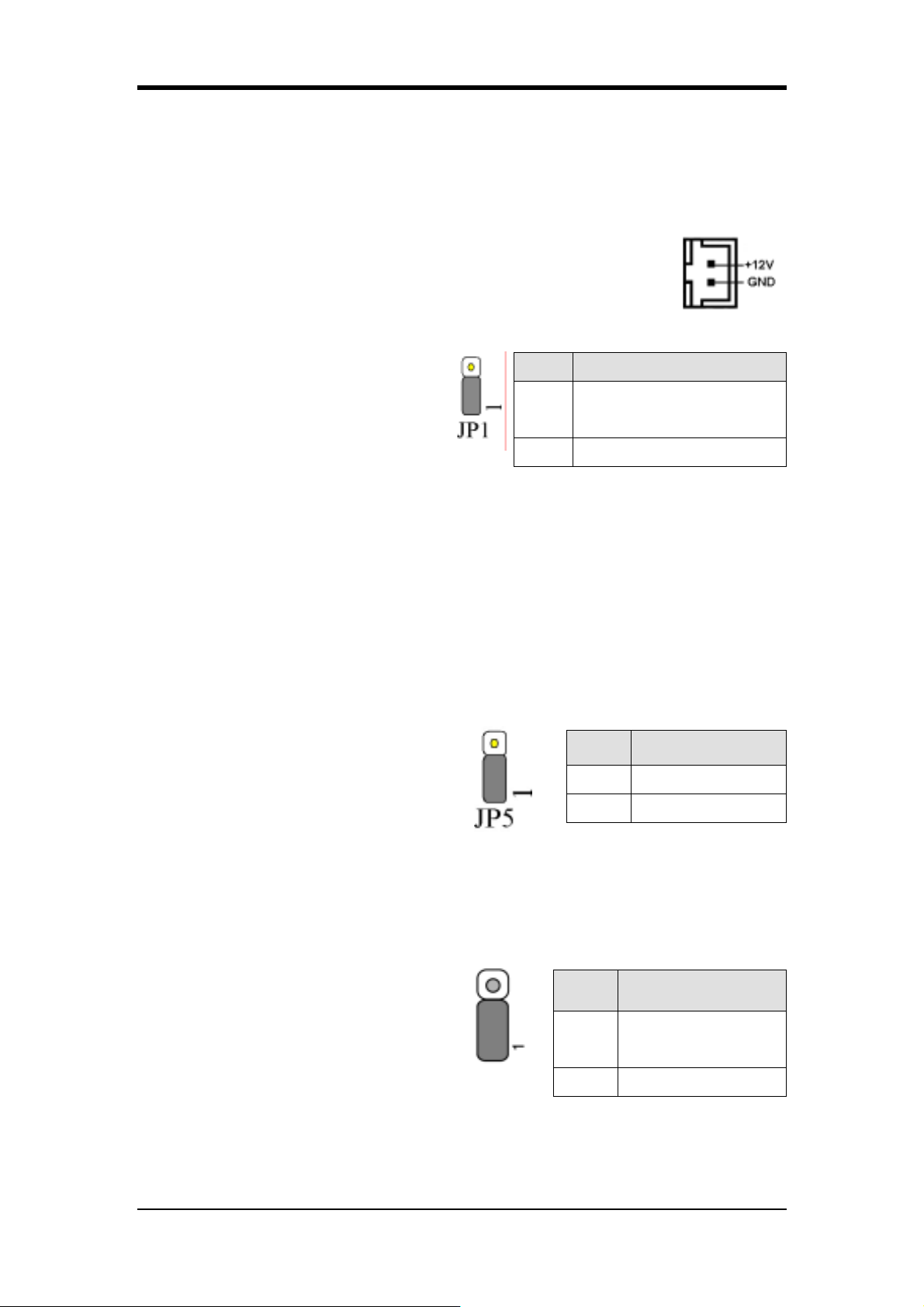
FAN 5 (connecteur Heat-Pipe)
Ce connecteur est utilisé pour relier le système Heat-Pipe à la carte
mère.
JP1 (Cavalier Effacer CMOS):
Il y a une RAM CMPS interne
Broche Définition
alimentée par une batterie externe pour
conserver les données et la
configuration du système. Pour effacer
le contenu du CMOS, veuillez suivre les étapes
1-2
2-3 Effacer les Données CMOS
Normal
(par défaut)
ci-dessous.
1. Débranchez l’alimentation système de la source d’alimentation.
2. Positionnez le cavalier à l’emplacement [2-3] pendant <5 secondes>, et
remettez-le ensuite dans sa position par défaut.
3. Connectez l’alimentation du système et redémarrez ensuite le système.
4. Entrez dans l’Utilitaire Setup CMOS du BIOS et choisissez « Load Setup
Defaults ». Tapez [O] et appuyez ensuite sur [Entrée] pour continuer.
5. Paramétrez la configuration du système dans le menu Setup CMOS Standard.
JP5 (KB/MS Power On)
Cette carte peut être mise en marche par
clavier PS/2 (touche de raccourci). Pour
utiliser cette fonction, sélectionnez une
Broche Définition
1-2 Désactivé
2-3 Activé
touche de raccourci de votre choix dans
l’option Eveil par Clavier PS2 à partir de S3 dans Evénements d’Eveil de l’écran de
Gestion d’Alimentation du BIOS. Vous devez aussi positionner ce cavalier sur les
broches [2-3] pour utiliser cette fonction.
JP6 (Power Ob by USB 2/3)
JP6 USB 2/3
Une touche de raccourci d’un clavier USB
ou un clic avec une souris USB peut
activer cette carte. Pour utiliser cette
fonction, sélectionnez une touche de
Broche Définition
Désactivé
1-2
(par défaut)
2-3 Activé
raccourci de votre choix dans l’option Reprise USB à
partir de S3 dans les Evénements d’Eveil de l’écran de Gestion d’Alimentation du
BIOS. Vous devez aussi positionner ce cavalier sur les broches 2-3 pour utiliser cette
fonction.
37
Page 46
Chapter 2
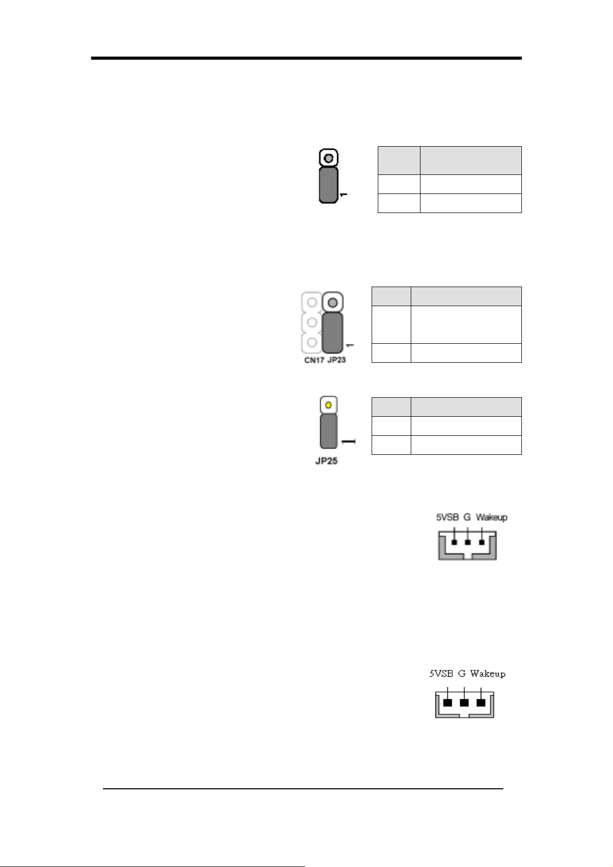
JP6A/JP6D (Activer/Désactiver le Cavalier D’Alimentation de
Périphérique USB 4/5, 0/1)
JP6A USB 4/5 JP6D USB 0/1
Une touche de raccourci d’un clavier
USB ou un clic avec une souris USB
peut activer cette carte. Pour utiliser
Broche Définition
1-2 Désactivé
cette fonction, sélectionnez une touche
2-3 Activé
de raccourci de votre choix dans
l’option Reprise USB à partir de S3 dans les Evénements d’Eveil de l’écran de
Gestion d’Alimentation du BIOS. Vous devez aussi positionner ce cavalier sur les
broches 2-3 pour utiliser cette fonction.
JP23 (LED de Mode Verte):
Ce cavalier permet d’activer le mode
Broche Définition
CHAINTECH
1-2
flash LED verte. (Optionnel)
(par défaut)
2-3 OEM
JP25 (ROM Table Select): Optionnel
Le système entre dans le Mode Utilisateur
lorsque les cavaliers sont laissés sur les
broches [1-2] durant le processus de
Broche Définition
1-2 User Mode
2-3 Safe Mode
démarrage. Autrement c’est le Mode
Sécurisé qui sera atteint si les cavaliers sont laissés sur les broches [2-3].
CN5 [Connecteur WOL (Wake-on-LAN)]:
Active la sélection Wake Up On LAN (Eveil par Réseau) dans le
Menu de Gestion d’Alimentation du BIOS pour utiliser cette
fonction La capacité de gérer les PC à distance à travers des
réseau est un facteur significatif dans la réduction des coûts administratifs et de
possession. La technologie Magic Packet est destinée à apporter la fonction WOL au
contrôleur LAN. Ce connecteur est utilisé pour relier une NIC (Network Interface
Card) supplémentaire offrant la fonction WOL à la carte mère.
CN5A [Connecteur WOM (Wake-on-Modem)]:
Active la sélection Wake Up On Modem (Eveil par Modem)
dans le Menu de Gestion d’Alimentation du BIOS pour activer
cette fonction. Cette embase est utilisée pour connecter une
carte modem supplémentaire offrant la fonction WOM à la
carte mère.
38
Page 47
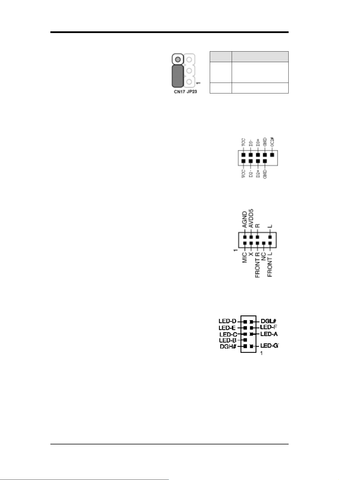
CN17 (Connecteur LED Bleu)
Chapter 2
Ces caractéristiques fonctionnent
comme le voyant LED d’alimentation,
tous deux affichent l’état
d’alimentation du système. La seule
Broche Définition
CHAINTECH
1-2
(par défaut)
2-3 OEM
différence est qu’une LED est bleue et
l’autre est rouge.
CN23/CN23C (Connecteur USB pour USB 4/5 et 0/1):
USB Port 4/5 CN23 USB Port 0/1 CN23C
Si vous voulez utiliser un Clavier USB, vous devez activer la
fonction de support de clavier USB dans le menu de
Périphériques Intégré du BIOS (Voir Section 3-30). Cette carte
contient un contrôleur d’Hôte USB et un hub racine, avec deux
connecteurs, est inclus pour un Adaptateur USB optionnel
(USB 0/1 et 4/5).
CN24 (Connecteur Audio de Panneau Avant CBOX 3 ):
Ce connecteur vous donne la possibilité de brancher un câble
ext. Permettant l’utilisation de la prise audio d’un panneau
avant, personnalisé à un boîtier système. Retirez simplement le
cavalier double des broches [5-6] et [9-10] puis branchez-le
sur le connecteur ext. du câble (optionnel). Les broches [5-6]
et [9-10] sont reliées (par défaut) pour activer la
fonction audio du panneau arrière.
CN25 (Connecteur d’Affichage du Système CBOX™ 3 DigiDoc):
Le CBOX3 intègre le [DigiDoc] exclusivité de CHAINTECH,
l’affichage de surveillance diagnostique le système de façon
avancé.
Affichage de diagnostic de PORT 80 pendant le POST
au démarrage du système!
Surveillance de la température du CPU, votre système
ne chauffe jamais !
DigiDoc est le docteur de votre système!
Reportez-vous à l’Appendice Liste des Codes d’Erreur de POST du Port 80
(Version Anglaise)
39
Page 48
Chapter 2
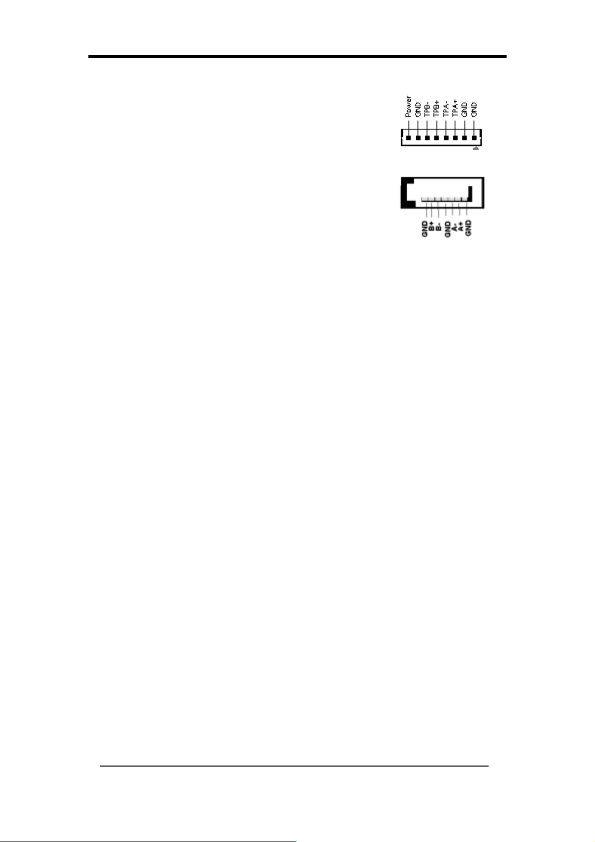
CN26B (Connecteur IEEE1394)
Reliez le câble connecteur série IEEE 1394 au bracket
1394 et au panneau frontal CBOX™.
SATA 0/1/2/3 (Connecteur Série ATA)
Il peut se connecter au nouveau périphérique IDE ; il
supporte l’ATA 150Mo/sec.
40
Page 49
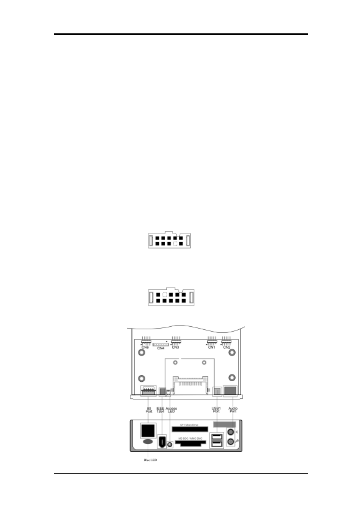
2-17 Installation de CBOX™ 3
1. Insérez doucement la CBOX™ 3 dans une baie 5-1/4” située à l’avant du châssis
système et serrez les vis latérales.
2. Connectez la Carte mère à CBOX™ 3:
Fonction Carte Mère CBOX™ 3
USB 4 & 5 CN23 CN1
USB 0 & 1 CN23C CN3
*Audio Avant CN24 CN2
IEEE 1394 CN26 CN4
Affichage Port 80 CN25 CN6
Chapter 2
Attention : Pour une bonne installation du CBOX
3 merci d'aligner le fil rouge des
câbles Audio et de l'affichage Port 80 avec les flèches respectives des connecteurs
CN2 et CN6.
*Retirez le cavalier CN24 sur la carte mère 5-6, 9-10 avant l’installation.
Câble USB (10 broches) x 2
Câble Audio Avant (10 broches) x 1
Câble IEEE-1394 (8 broches) x 1
Affichage Port 80 (10 broches) x 1
41
Page 50
Chapter 2
Le code erreur “FF” est une indication NORMALE sur les CBOX2/CBOX3
sous tout SE (Système d’exploitation) lorsque qu’il a démarré. C’est
uniquement après l’installation et l’activation des logiciels APOGEE
Overclocking Utility ou DigiDoc* (*selon le modèle de votre carte mère)
que les CBOX2/CBOX3 afficheront la température actuelle de CPU.
Merci de visiter le site http://www.chaintech.com.tw pour obtenir les
dernières versions des logiciels APOGEE Overclocking Utility et
DigiDoc.
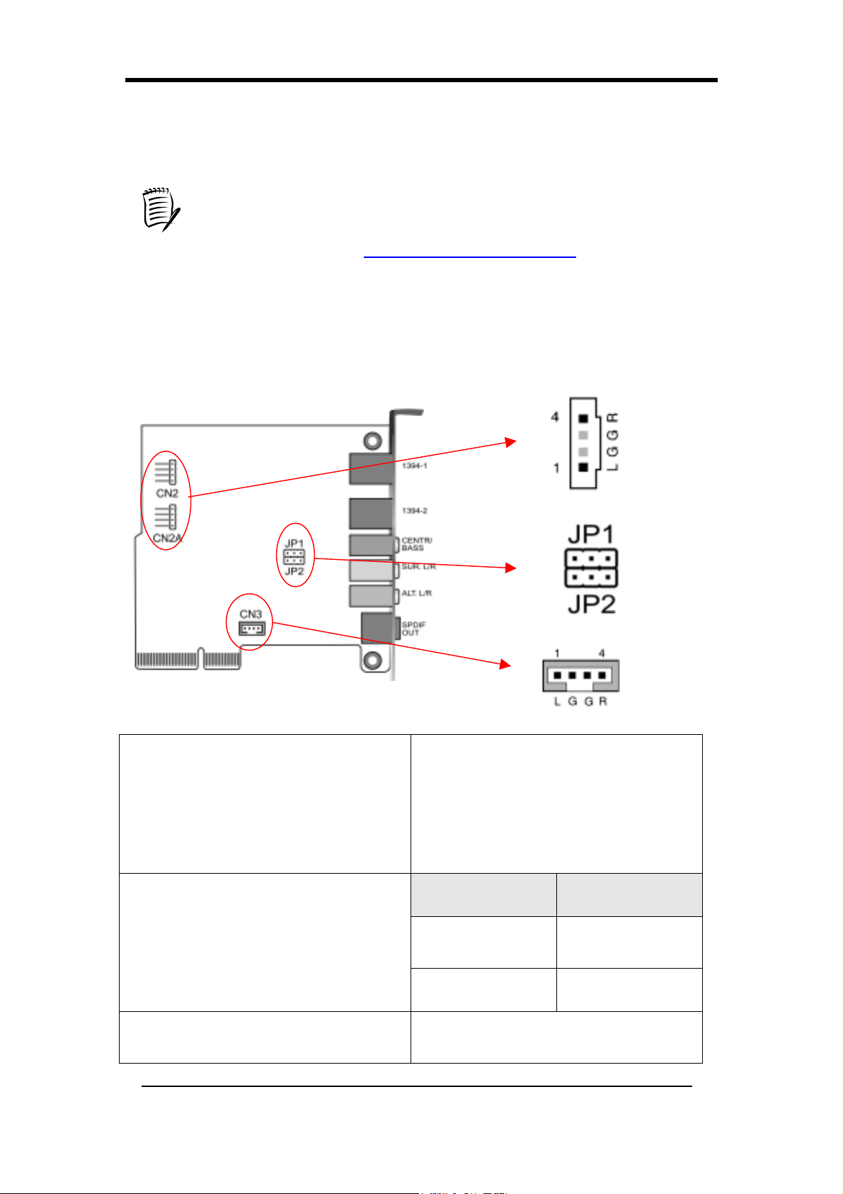
2-18 Installation de CMC (Carte Multimédia Chaintech)
CN2/CN2A
(Connecteur d’Entrée Audio CD-ROM)
JP1/JP2
(Sélection Basse/Médium)
CN3
(Connecteur d’Entrée Audio Auxiliaire)
42
Utilisez le câble audio qui accompagne
votre lecteur CD-ROM pour connecter
le CD-ROM à votre carte mère. Cela
vous permettra d’utiliser à la fonction
audio de votre CD-ROM.
Broche Définition
1-2 Normal
(par défaut)
2-3 Echange
Ce connecteur est destiné aux
Périphériques Audio AUX.
Page 51
Chapter 2
Hardware-Setup(German)
Dieses Kapitel enthält auch Informationen für den Fall, daß das Motherboard bereits im
Computer installiert wurde, z.B. wenn die Systemhardware aufgerüstet werden soll.
Dieses Motherboard ist sehr empfindlich gegenüber statischer Ladung. Berühren Sie es nur
mit geeignetem Sicherheitszubehör und trennen Sie immer erst das Stromkabel von der
Netzsteckdose, wenn Sie mit dem Motherboard in Kontakt kommen. Anderenfalls besteht
Stromschlaggefahr!
2-19 Installation einer CPU im Sockel 754
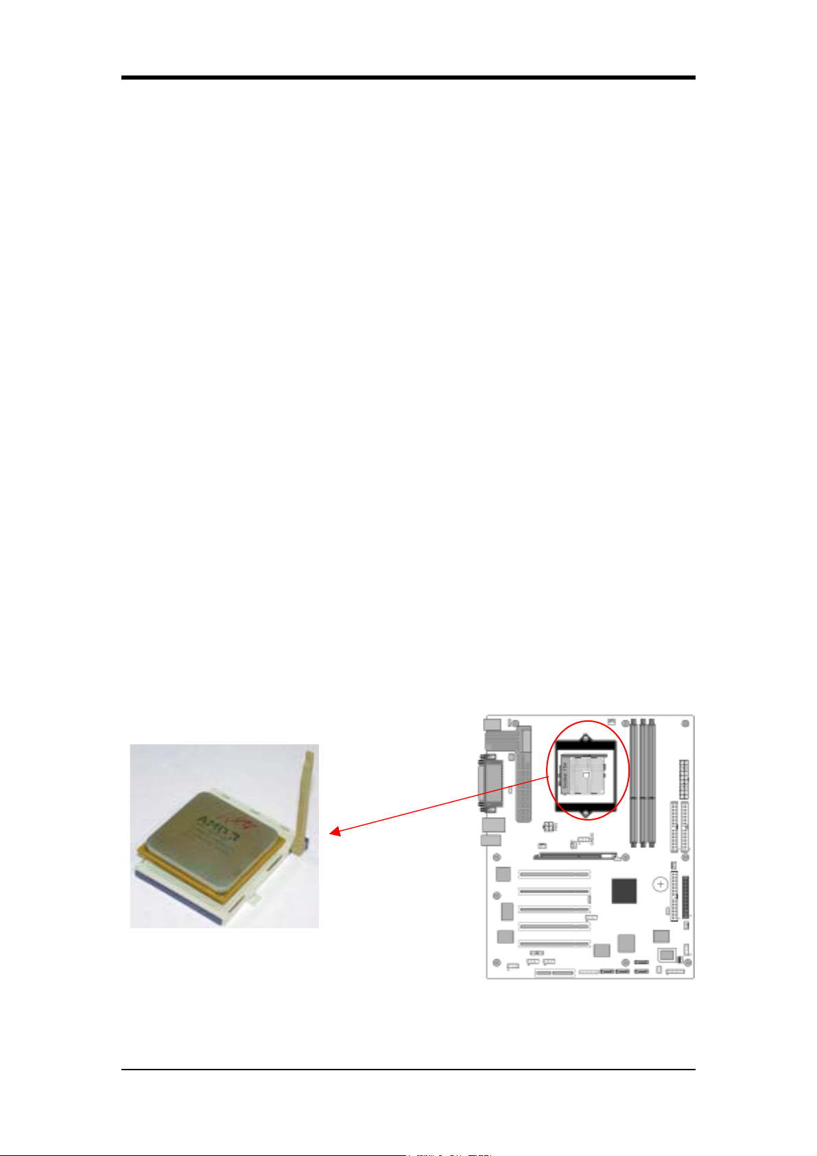
Der Sockel 754, der für Prozessoren des Typs AMD Athlon 64 geeignet ist, wurde als ein
Standardmerkmal in das Motherboard integriert. Die CPU wird folgendermaßen in den
Sockel 754 eingesetzt:
1. Auf der Oberseite der CPU finden Sie nahe einer der Ecken eine Markierung. Ebendiese
Ecke der CPU ist auch als deutliches Kennzeichen abgeschnitten. Diese Markierungen
kennzeichnet den Pin-1 der CPU.
2. Ziehen Sie den Hebel des Sockels A so weit hoch, daß er senkrecht zum Motherboard steht.
Setzen Sie die CPU vorsichtig so ein, daß sich die Pin-1-Position am Anfang des
Sockelhebels von Sockel 754 befindet. Die CPU wird durch ihr Eigengewicht in den Sockel
gedrückt. Helfen Sie nicht nach, da dabei die CPU beschädigt werden könnte. Klappen
Sie den Hebel wieder herunter.
Um eine ausreichende Hitzeableitung von der CPU zu gewährleisten, ist es notwendig, ein
von AMD anerkanntes Lüftermodul zu installieren. Anderenfalls kann die CPU überhitzt
und dadurch beschädigt werden.
Hinweise: Damit das System mit einer neu eingesetzten CPU starten kann, muß der
AC-Strom vor der Installation abgeschaltet werden.
43
Page 52
Chapter 2
2-20 Konfiguration der CPU-Jumper
Einstellung der Frequenz:
Diese Frequenz wird automatisch durch die jeweils verwendete CPU eingestellt.
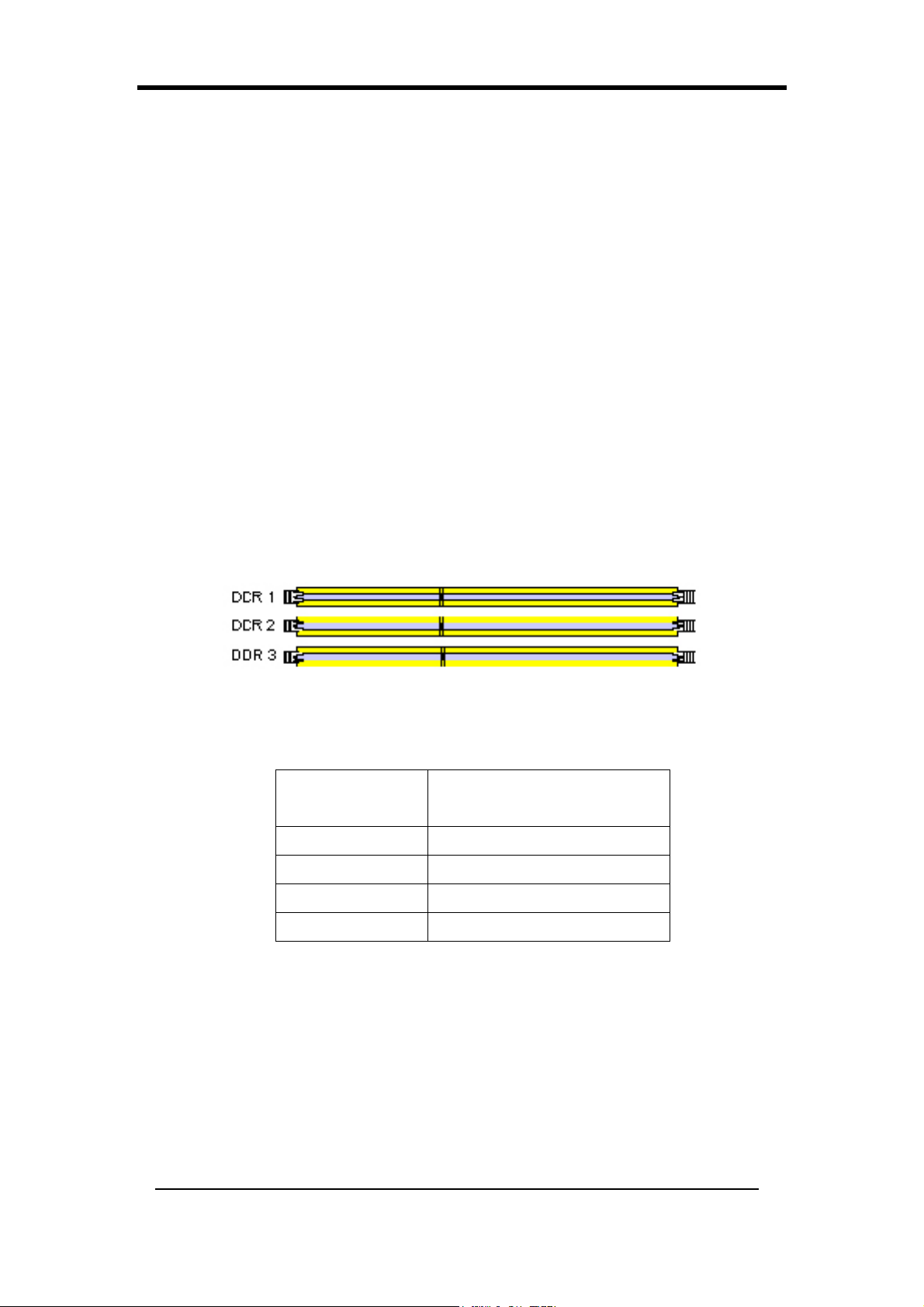
2-21 Konfiguration des Hauptspeichers
Das DDR SDRAM Speichersysteme besteht aus 3 Bänken. Die erste Bank
unterstützt bis maximal 1GB Arbeitsspeicher, die zweite und dritte Bank
unterstützen zusammen bis zu maximal 1GB Arbeitsspeicher. Wir empfehlen die
Installation der DRAMs entweder in Bank 1&2 (DIMM1+DIMM2) oder Bank 1&3
(DIMM1+DIMM3). Die Bestückung der Bänke 2&3 (DIMM2+DIMM3) kann zu
instabilem Systemverhalten führen.
Beachten Sie bitte auch im Anhang die Kompatibilitätsliste für die Verwendung von
Speichermodulen.
DDR-SDRAM-Spezifikationen
Speicherfrequenz
100 MHz 200 MHz
133 MHz 266 MHz
166 MHz 333 MHz
200 MHz 400 MHz
Frequenz des internen
Systembus
DIMM-Typ: 2,5 V, nicht gepufferter DDR-SDRAM mit 184 Pins und
64/128/256/512-Bit
Modulgröße: Single/double-sided 64/128/256/512MB/1GB
Parität: Parität oder keine Parität
Beachten Sie bitte auch den Anhang für detaillierte Information über DDR DRAM
Unterstützung.
44
Page 53
Chapter 2
Position
64 MB 128 MB 256 MB 512 MB 1 GB
DDR 1 X X X X X
DDR 2
DDR 3 X X X X X
X
X X X X
2-22 Verkabelungs- und Jumper (Steckbrücken)-Setup
Die Verkabelung wird eingesetzt, um die Systemplatine (das Mainboard) mit
anderen Teilen des Systems zu verbinden, inklusive Netzteil, Tastatur und
verschiedener Steuerelemente und Anschlüsse an der Vorderseite des Gehäuses.
Bei der Installation eines Mainboards wird das Netzteilkabel zuletzt
angeschlossen. Bevor Sie das Netzteil anschließen, achten Sie darauf, dass
es nicht mit dem Stromnetz verbunden ist (Netzstecker nicht eingesteckt).
Sämtliche Kabel von CHAINTECH werden mit einem Sicherheitsbeleg
geliefert.
PW 1 / 3 (ATX-Netzteilverbindung)
Das Netzkabel zwischen System-Netzteil und externer
Stromquelle (Steckdose) muss beim Zusammenstellen
eines Systems als letztes angeschlossen werden. Das
ATX-Netzteil verfügt über einen einzigen, 20-poligen
Verbindungsstecker, über den die Standardsignale wie +/- 5
V, +/- 12, optionale 3,3 V- und Soft-power-Signale geleitet
werden. An der Soft Power-Signalleitung liegt ein 5
V-Dauersignal an, wenn Netzspannung zur Verfügung steht.
Wenn sich das System im Soft-Off-Modus befindet,
unterhält diese Dauerstromversorgung die
Minimalversorgung des Systems.
Das ATX 12 V-Netzteil verfügt über einen neuen +12 V
(4-polig)- und +5 V / 3,3 V (6-polig) –Zusatzstromstecker,
um zusätzlichen +12 VDC- und +5 / 3,3 VDC-Strom für das Mainboard zu liefern.
Power-On By Modem (Einschalten bei Modem-Aktivität)
Während sich das System im Soft-Off-Status befindet, so wird das System aktiviert
(eingeschaltet) und kann per Fernzugriff bedient werden, wenn ein externes
Anrufsignal am Modem erkannt wird. Die können diese Funktion im Power
Management Setup-Menü im BIOS aktivieren. (Siehe Abschnitt 3-44.)
45
Page 54
Chapter 2
Blinkende LED im Suspend-Modus
Im Suspend-Modus (unter Windows auch „Ruhezustand“ genannt), blinkt die LED an
der Vorderseite Ihres Computers. Der Suspend-Modus wird durch den grünen
„Override Power Button“ an Ihrem ATX-Gehäuse oder durch Aktivieren der Power
Management- und Suspend Mode-Optionen im Power Management-Menü des BIOS
aktiviert. (Siehe Abschnitt 3-44.)
Poly-fuse-Überspannungsschutz
Die Poly-fuse (eine wiederverwendbare Sicherung) schützt Ihr System vor
gefährlichen Spannungen, die an den Tastatur- oder USB-Anschlüssen auftreten
können. In solchen Fällen unterbricht die Poly-fuse den entsprechendenStromkreis
wie eine normale Sicherung. Nach einer gewissen Abschaltungszeit wechselt die
Poly-fuse wieder in ihren normalen Arbeitszustand, Tastatur- und USB-Anschluss
funktionieren wieder korrekt. Anders als herkömmliche Sicherungen muss die
Poly-fuse nicht ersetzt werden und erspart Anwendern dadurch diese
Anannehmlichkeiten.
CN1A (Frontbedienfeld-Stecker)
PWR-SW (Override Power Button-Anschluss):
Der Netzschalter eines ATX-Systems kann sowohl als
normaler Netzschalter als auch dazu verwendet werden, das
System in den Advanced Power Management
Suspend-Modus zu versetzen. Dies ist eine Methode, um
Energie zu sparen, wenn der Computer längere Zeit nicht
verwendet wird. Die Funktion Soft-OFF by PWR-BTTN
im Power Management Setup-Menü des BIOS muss auf
[Delay 4 Sec.] eingestellt werden, um diese Funktion zu
aktivieren.
Wenn die Funktion Soft-OFF by PWR-BTTN aktiviert ist, so wird das System bei
Betätigung des Netzschalter unverzüglich in den Suspend-Modus versetzt. Jede Art
externer Aktivität – wie Betätigen von Tasten an der Tastatur oder
Mausbewegungen – lassen das System wieder in den Normalbetrieb wechseln. Wird
der Netzschalter bei Normalbetrieb des Systems länger als [4 Sekunden] betätigt, so
wird das System komplett abgeschaltet. Siehe Override Power Button
Operation-Diagramm.
P-LED (Betriebsanzeige-LED-Anschluss):
Die Betriebsanzeige-LED zeigt den Betriebszustand des Systems. Es ist wichtig,
besonders auf korrekte Verkabelung und Pin-Ausrichtung zu achten (Geben Sie
acht, nicht die Reihenfolge dieser beiden Anschlüsse durcheinander zu bringen.)
46
Page 55
G-BTN (Green Button Switch):
An manchen ATX-Gehäusen befindet sich ein „Green Button“-Schalter, der
verwendet wird, um das System in den Suspend-Modus zu versetzen. Im
Suspend-Modus liefert das Netzteil nur noch einen Bruchteil an Strom, der
CPU-Takt wird gestoppt, der CPU-Kern auf geringste Leistung reduziert. Das
System wird wieder aktiviert, indem Tastatur oder Maus betätigt werden. Der
Wiederanlauf des Systems kann auf verschiedene Arten erfolgen, wie im Power
Management Setup-Bildschirm des BIOS vorgegeben.
RESET (System-Resettaster-Anschluss):
Dieser Stecker sollte an den Reset-Taster an der Vorderseite des Systemgehäuses
angeschlossen werden. Der Reset-Taster ermöglich Ihnen den Neustart des
Systems, ohne es ausschalten zu müssen.
SPEAKER (Lautsprecher-Anschluss):
Dieser 4-polige Verbinder wird an den Gehäuselautsprecher angeschlossen.
HD-LED (Anschluss für IDE-Aktivitäts-LED):
Chapter 2
Die IDE-Aktivitäts-LED leuchtet auf, wenn das System von IDE-Geräten liest oder
auf diese schreibt.
FD1 (Diskettenlaufwerk-Anschluss)
Das Mainboard verfügt über einen Standardanschluss für
Diskettenlaufwerke, der 360K-, 720K-, 1,2M-, 1,44 M- und
2,88M-Diskettenlaufwerke unterstützt. An diesen Anschluss werden
Diskettenlaufwerke mit 34-poligem Stecker angeschlossen.
IDE 1/2/3 (IDE-Festplattenanschluss)
Das Mainboard verfügt über einen 32-bit Enhanced PCI IDE und
Ultra ATA66/100-Controller, der PIO mode 0 - 4, Bus Master- und
Ultra ATA66/100-Funktion bietet. Dieser Anschluss wird zum
Anschluss 40-poliger ATAPI-Geräte verwendet.
IDE 1 wird verwendet, wenn nur bis zu zwei IDE-Geräte
angeschlossen werden. (Primary Master / Slave)
IDE 2 wird für bis zu zwei zusätzliche IDE-Geräte verwendet.
(Secondary Master / Slave)
IDE 3 wird für bis zu zwei zusätzliche IDE-Geräte verwendet. (Tertiary Master /
Slave)
47
Page 56
Chapter 2
FAN1/2/3/4 (CPU- / System- / Case Fan/ Chip
Fan-Kühlungslüfteranschlüsse):
Das Hardware-Management des Mainboards kann die
Umdrehungsgeschwindigkeit von CPU- und Systemlüftern
in rpm (Umdrehungen pro Minute) erkennen. Verkabelung und
Stecker können je nach Hersteller unterschiedlich ausfallen. Bei
Standard-Lüftern entspricht das rote Kabel +12 V, das schwarze Kabel der Masse, das
gelbe Kabel liefert die Umdrehungsinformation. Schließen Sie einen North
Bridge-Kühlungslüfter an FAN4 an.
FAN 5 (Heat-Pipe Anschluss)
Dieser Anschluss wird zur Verwendung mit einem
Heat-Pipe-System benötigt.
JP1 (Jumper zum Löschen der CMOS-Daten)
Auf dem Mainboard befindet sich ein
CMOS-RAM, das mit einer externen Batterie
mit Strom versorgt wird, um Datum und
Pin Definition
Normal
1-2
Systemkonfiguration zu speichern. Um die
Inhalte des CMOS zu löschen, folgen Sie bitte
2-3 CMOS-Daten löschen
(Standard)
den nachfolgenden Schritten.
1. Trennen Sie die Stromversorgung des Netzteils (Netzstecker ziehen).
2. Überbrücken Sie mit einem Jumper (Steckbrücke) die Pins [2-3] <5 Sekunden> lang,
stecken Sie den Jumper dann wieder in die Normalposition zurück.
3. Schließen Sie das Netzkabel wieder an und starten Sie das System.
4. Rufen Sie das BIOS CMOS Setup Utility auf und wählen Sie „Load Optimized
Defaults“. Drücken Sie [Y] (bei deutscher Tastatur meist mit der Taste „Z“ zu
erreichen) und dann [Enter] zum Fortfahren.
5. Stellen Sie die Systemkonfiguration im Standard CMOUS Setup-Menü ein.
JP5 (KB/MS Power On)
Dieses Motherboard kann durch drücken einer
Pin Definition
Tastenkombination der PS/2-Tastatur
eingeschaltet werden. Um diese Funktion
1-2 Deaktiviert
2-3 Aktiviert
nutzen zu können, müssen Sie zunächst im
Power Management Setup des BIOS bei Wake Up Events die Option „Hot Key Power
ON“ auswählen. Außerdem müssen Sie den Jumperschalter auf [2-3] setzen.
48
Page 57
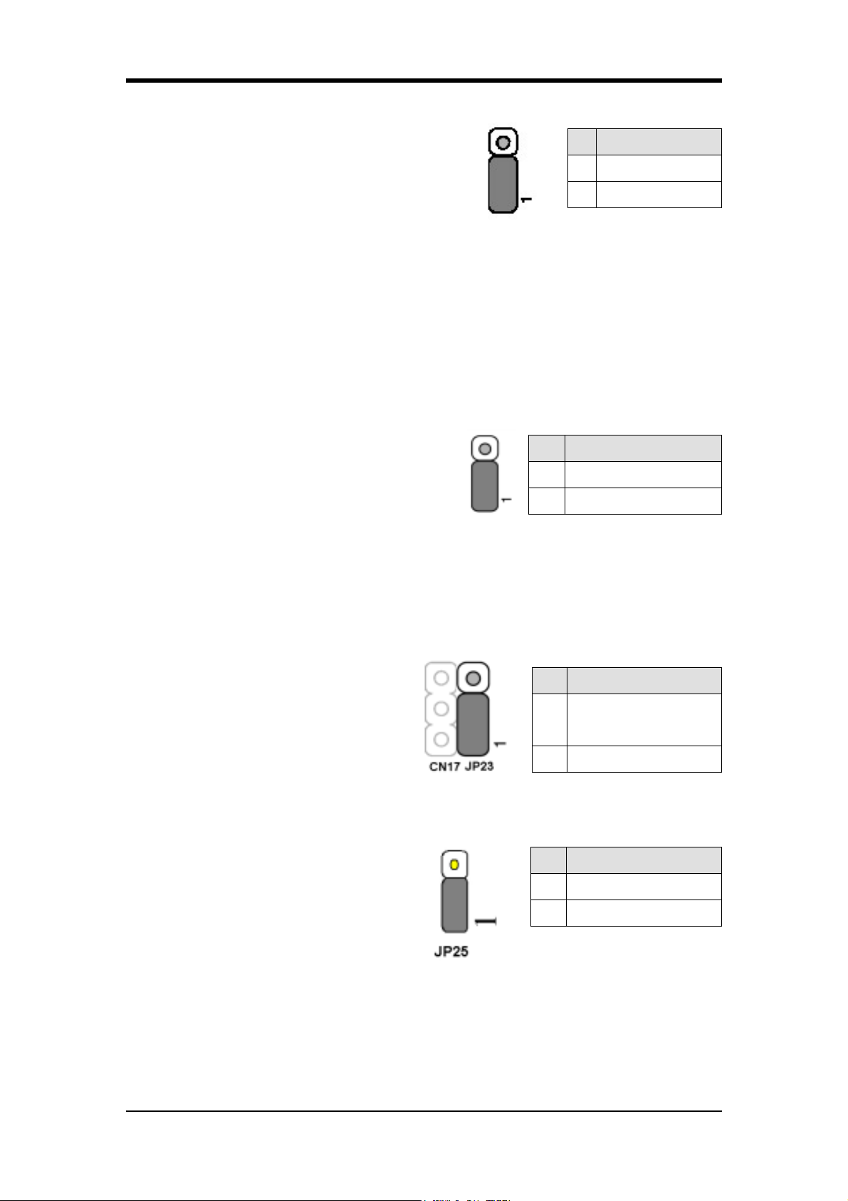
JP6 (Power on By USB 2/3)
Chapter 2
JP6 -> USB 2/3
Eine bestimmte Taste einer USB-Tastatur oder
ein USB-Mausklick kann zur Aktivierung
Pin Definition
1-2 Deaktiviert
2-3 Aktiviert
dieses Mainboards verwendet werden. Um
diese Funktion zu nutzen, wählen Sie im Power On Management-Bildschirm des
BIOS unter Wake Up Events / USB Resume from S3 eine Taste (hot key) Ihrer Wahl.
Darüber hinaus müssen Sie die Pins 2-3 mit dem Jumper überbrücken, um diese
Funktion nutzen zu können.
JP6A / JP6D (Aktivieren / Deaktivieren USB 4/5, 0/1 Device Power
ON-Jumper)
JP6A USB 4/5 JP6D USB 0/1
Eine bestimmte Taste einer USB-Tastatur oder
Pin Definition
ein USB-Mausklick kann zur Aktivierung
1-2 Deaktiviert
dieses Mainboards verwendet werden. Um
2-3 Aktiviert
diese Funktion zu nutzen, wählen Sie im
Power On Management-Bildschirm des BIOS unter Wake Up Events / USB Resume
from S3 eine Taste (hot key) Ihrer Wahl. Darüber hinaus müssen Sie die Pins 2-3 mit
dem Jumper überbrücken, um diese Funktion nutzen zu können.
JP23 (LED für "grünen" Modus):
Mit diesem Schalter wird das Verhalten
der "grünen" LED für den
Stromsparmodus eingestellt (optional).
Pin Definition
CHAINTECH
1-2
(Standard)
2-3 OEM
JP25 (Auswahl ROM Tabelle) : Optional
Das System startet im Benutzermodus,
wenn die Brückenstecker Jumper) sich
auf den Pins 1-2 befinden. Bei gesteckten
Brückensteckern (Jumper) auf den
Pin Definition
1-2 User mode
2-3 Safe Mode
Pins 2-3 startet das System in den
gesicherten Modus (Safe Mode).
49
Page 58
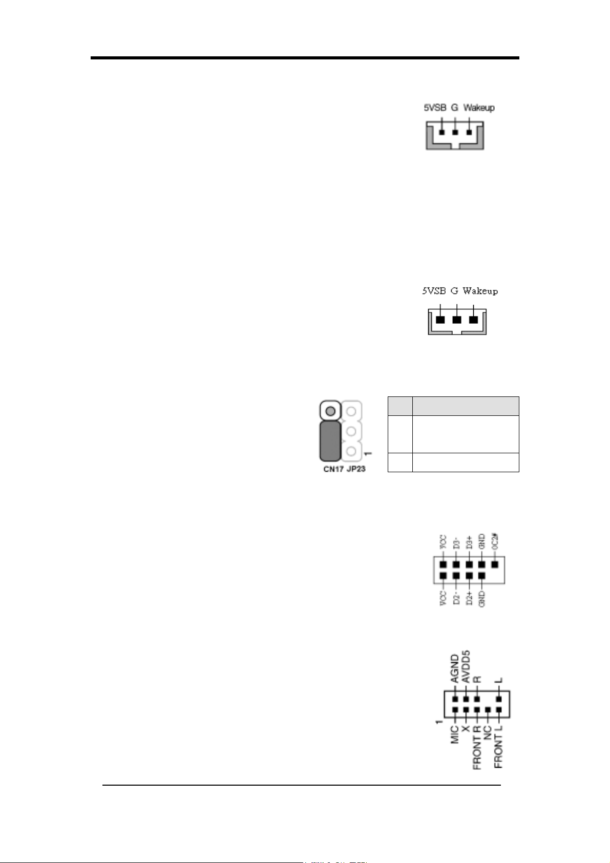
Chapter 2
CN5 [WOL (Wake-on-LAN)-Anschluss]:
Um diese Funktion zu benutzen, aktivieren Sie im Power
Management-Menü des BIOS den Punkt Wake Up On LAN.
Die Fähigkeit, PCs aus der Ferne über Netzwerke zu verwalten,
ist ein bedeutender Faktor bei der Reduktion von Administrations- und
Betriebskosten. Die Magic Packet-Technologie wurde entwickelt, um
WOL-Funktionalität für LAN-Controller zu schaffen. Dieser Header wird zum
Anschluss einer zusätzlichen Netzwerkkarte (NIC) verwendet, die
WOL-Funktionalität für das Mainboard zur Verfügung stellt.
CN5A [WOM (Wake-on-Modem)-Anschluss]:
Um diese Funktion zu verwenden, aktivieren Sie im Power
Management-Menü des BIOS den Punkt Wake Up On Modem.
Dieser Header wird zum Anschluss einer zusätzlichen
Modemkarte verwendet, die WOM-Funktionalität für das
Mainboard zur Verfügung stellt.
CN17 (Anschluss für blaue LED):
Diese Funktion arbeitet genau die die
Pin Definition
Betriebsanzeige-LED – beide dienen zur
Anzeige des Betriebsstatus des Systems.
Der einzige Unterschied besteht darin,
1-2
2-3 OEM
dass diese LED blau, die andere rot ist.
CN23/CN23C (USB-Anschluss für USB 4/5 und 0/1):
USB Port 4/5 CN23 USB Port 0/1 CN23C
Wenn Sie eine USB-Tastatur verwenden möchten, müssen Sie
die Funktion zur USB-Tastaturunterstützung im Integrated
Peripherals-Menü des BIOS aktivieren. Dieses Mainboard
verfügt über einen USB-Hostcontroller und einen
Root-Anschluss mit zwei Verbindern für einen optionalen
USB-Adapter )USB 0/1 und 4/5).
CHAINTECH
(Standard)
CN24 (CBOX™ 3 Front-Audio-Anschluss):
Dieser Anschluss ermöglicht Ihnen den Anschluss von
Audiokabeln an Frontanschlüsse, die bei speziellen
Systemgehäusen zur Verfügung stehen.
Ziehen Sie einfach die beiden Jumper von den Pins [5-6] und
[9-10]
ab und verbinden Sie die (optionalen) externen Kabel.Die Pins
50
Page 59
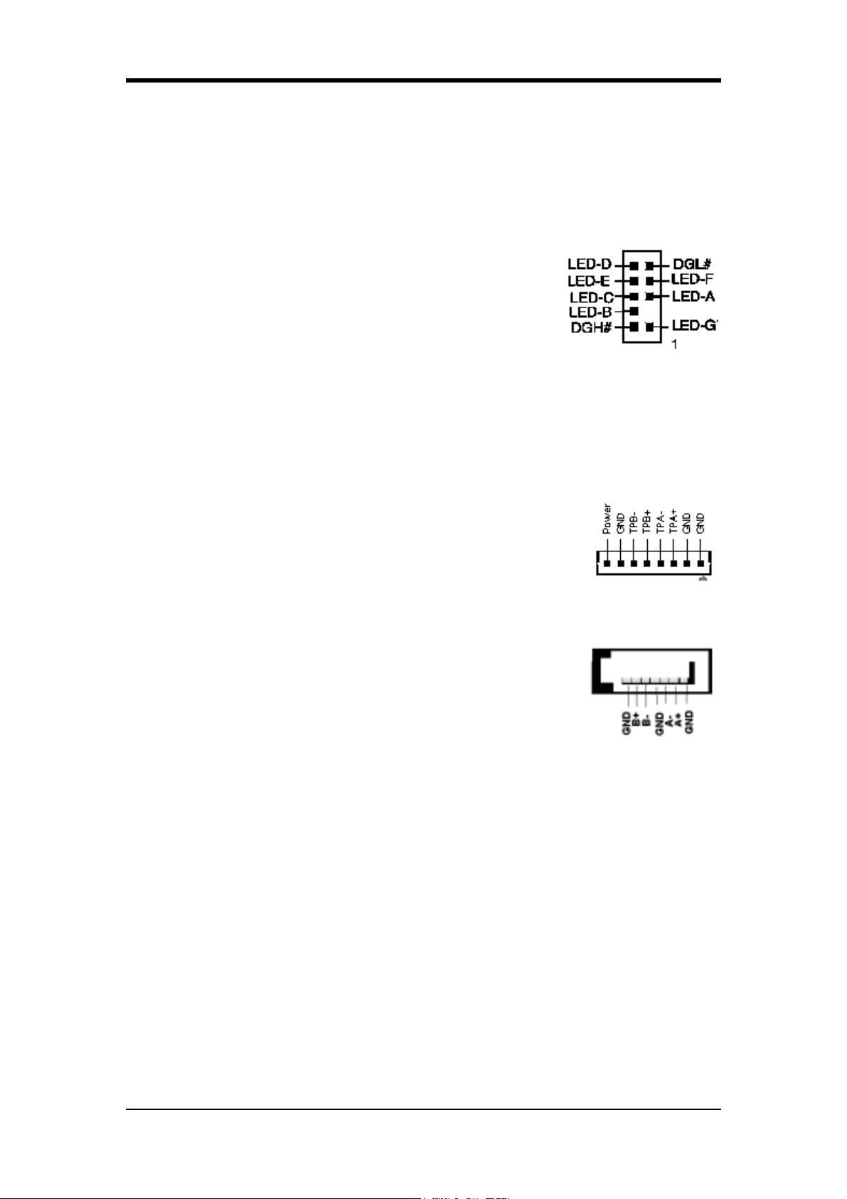
[5-6]
und [9-10] sind (standardmäßig) gebrückt, um die
Audiofunktionalität an den rückwärtigen Anschlüssen zu ermöglichen.
CN25 (CBOX™ 3 DigiDoc-Systemanzeige-Anschluss):
CBOX™3 verfügt über den exklusiven DigiDoc von
CHAINTECH, die fortschrittlichste Anzeige für
Systemdiagnostik und -überwachung.
- 80-PORT-Diagnoseanzeige während POST beim
Booten des Systems!
- CPU-Temperaturüberwachung, so bleibt Ihr System immer kühl!
- DigiDoc ist der Arzt Ihres Systems!
Details finden Sie im Anhang unter Digidoc 80-Port POST-Fehlercodeliste.
Chapter 2
CN26 (IEEE1394-Anschluss)
Schließen Sie ein serielles IEEE 1394-Kabel an die IEEE
1394-Blende und den CBOX™ 3-Frontanschluss an.
SATA1/2 (Serieller ATA-Anschluss):
Kann zum Anschluss neuerer IDE-Geräte verwendet werden;
unterstützt ATA 150MB/Sek.
51
Page 60
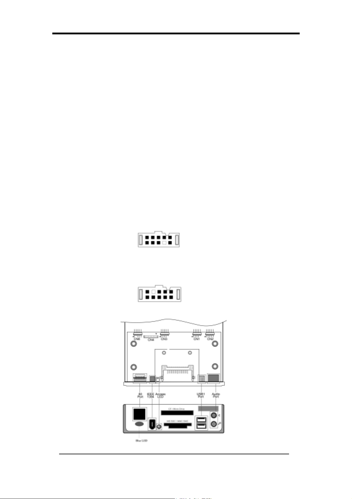
Chapter 2
2-23 CBOX™ 3-Setup
Setzen Sie CBOX™ 3 vorsichtig in einen normalen 5,25 Zoll-Laufwerkschacht an der
Vorderseite des Systemgehäuses ein und ziehen Sie die Schrauben an den Seiten fest
und sicher an.
Schließen Sie das Mainboard an CBOX™ 3 an:
Funktion Mainboard CBOX™ 3
USB 4 & 5 CN23 CN1
USB 6 & 7 CN23A CN3
*Front-Audio CN24 CN22
IEEE 1394 CN26B CN4
80 Port-Display CN25 CN6
Anzeige: Fuer eine richtigen Installation von CBOX3 richten Sie bitte den
roten Kanten auf die Audio und 80-port Anzeigekabeln auf die Pfeilen auf CN2
und CN6 Anschluesse auf.
Ziehen Sie die CN24-Jumper 5-6, 9-10 vor der Installation ab.
USB-Kabel (10-polig) x 2
Front-Audiokabel (10-polig) x 1
IEEE 1394-Kabel (8-polig) x 1
80 Port-Display (10-polig) x 1
52
Page 61
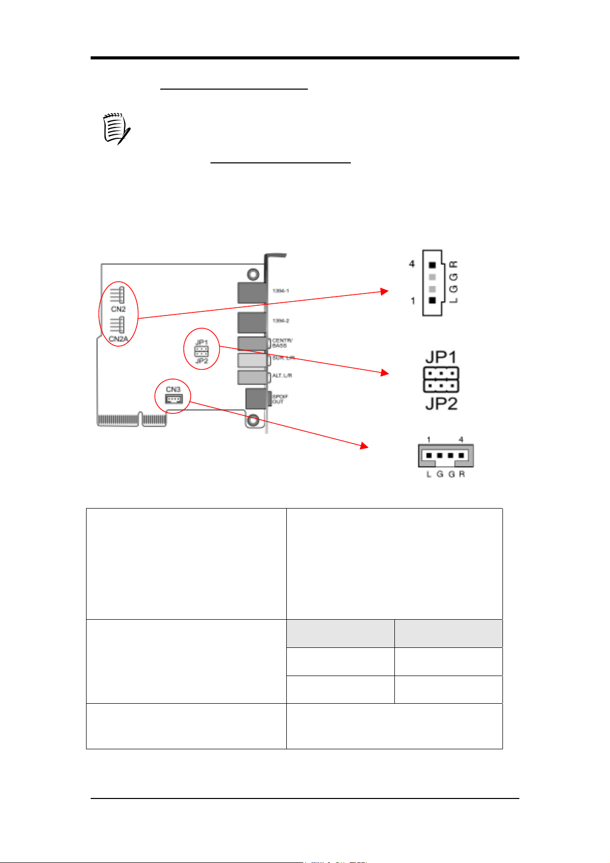
Es ist unter jeden Betriebssystem NORMAL wenn Fehlercode “FF” auf
CBOX2/CBOX3 angezeigt wird nachdem das System gestartet ist. Nur wenn
Apogee Overclocking Utility oder Digidoc richting installiert und aktiviert
sind wird CBOX2/CBOX3 den aktuellen CPU-Temperatur anzeigen.
Besuchen Sie http://www.chaintech.com.tw. für die neueste Apogee
Overclocking Utility und Digidoc Versionen.
2-24 CMC (Chaintech Multimedia Card)-Setup
Chapter 2
CN2/CN2A
(CD-ROM-Audio-Eingangsanschluss)
JP1/JP2
(Bass- / Center-Auswahl)
CN3
Verwenden Sie das mit Ihrem
CD-ROM-Laufwerk gelieferte Kabel
zum Anschluss des CD-ROM an Ihr
Mainboard. Dadurch werden die
Audio-Funktionen Ihres CD-ROMs
aktiviert.
Pin Definition
1-2 Normal (Standard)
2-3 Swap
Dieser Anschluss dient zum Anschluss
(Zusätzlicher Audio-In-Anschluss)
des AUX-Audiogerätes.
53
Page 62
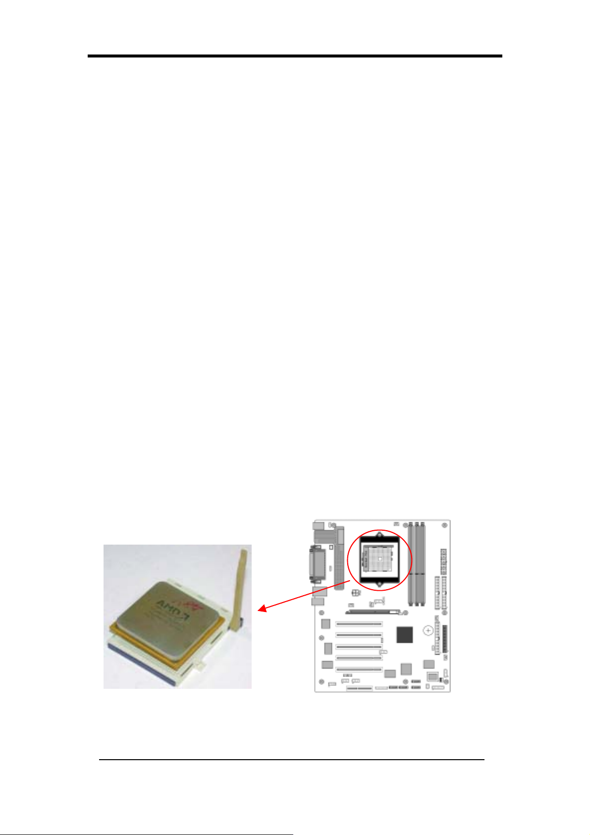
Chapter 2
Настройка аппаратных средств (Russian)
Если ваша системная плата уже была установлена в вашем компьютере, Вам
может быть придется обращаться к этой главе, если Вы планируете
модернизировать аппаратные средства вашего компьютера.
Эта системная плата чувствительна к электростатическим зарядам. Не
прикасайтесь к ней, не надев надлежащее устройство безопасности, и перед
выполнением любой работы на вашей системной плате удостоверьтесь в том,
что кабель питания отсоединен от источника питания. Несоблюдение этого
может привести к поражению электрическим током!
2-25 Установка процессора в разъем Socket 754
Разъем Socket 754, предназначенный для процессоров AMD Athlon 64, встроен
в качестве стандартного элемента системной платы. Для установки процессора
в Socket A, пожалуйста, проделайте следующее:
1. Найдите прорезь на верхней поверхности процессора, которая находится
вблизи одного из его углов. Этот угол также будет иметь скос, представляющий
заметную метку на углу процессора. Эти метки указывают расположение
вывода 1 процессора.
2.
Поднимите вверх рычажок разъема Socket 754 перпендикулярно к плоскости
системной платы. Осторожно вставьте процессор, расположив вывод 1 в угол
разъема Socket A вблизи конца рычажка. Пусть процессор сам войдет в разъем
под действием своего веса. Во избежание повреждений не прилагайте
излишних усилий. Защелкните рычажок в исходное положение.
Для надлежащего охлаждения процессора AMD обязательна установка
соответствующего радиатора с вентилятором. Отсутствие этих элементов
может привести к перегреву и возможному выгоранию вашего процессора.
Примечания: Для обеспечения начального пуска компьютера с новым
процессором перед его установкой следует выключить напряжение
переменного тока.
54
Page 63
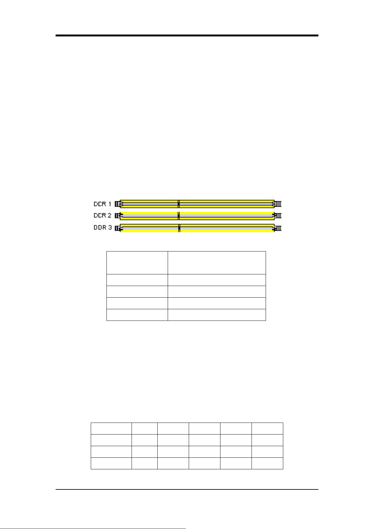
Chapter 2
2-26 Настройка процессора при помощи перемычек
Частота изменяется процессором автоматически.
2-27 Конфигурация основной памяти
Подсистема DDR SDRAM памяти состоит из трех банков. Первый банк
поддерживает до 1ГБ памяти, второй и третий вместе поддерживают до 1ГБ
памяти. Мы настоятельно рекомендуем устанавливать модули памяти либо в
слоты DIMM1 + DIMM2, либо в DIMM1 +DIMM3. Использование слотов
DIMM2 + DIMM3 не рекомендовано, т.к. может повлечь нестабильность
системы.
Пожалуйста, см. таблицу совместимости
DDR SDRAM в Appendix.
Характеристики памяти DDR SDRAM
Частота внутренней
Частота памяти
системной шины
100 MГц 200 MГц
133 MГц 266 MГц
166 MГц 333 MГц
200 MГц 400 MГц
Тип DIMM: 2,5 В, без буфера с числом выводов 184, память типа DDR
SDRAM 64/128/256/512-бит
Емкость модуля памяти: Одно/двусторонний 64/128/256/512 МБ/1 ГБ
Четность: Либо с проверкой на четность, либо без нее
Если Вам необходима информация по поддержке модулей DDR DRAM -
пожалуйста, смотрите Приложение.
Размещение 64 МБ 128 МБ 256 МБ 512 МБ 1,0 ГБ
DDR 1 X X X X X
DDR 2
X
X X X X
DDR 3 X X X X X
55
Page 64
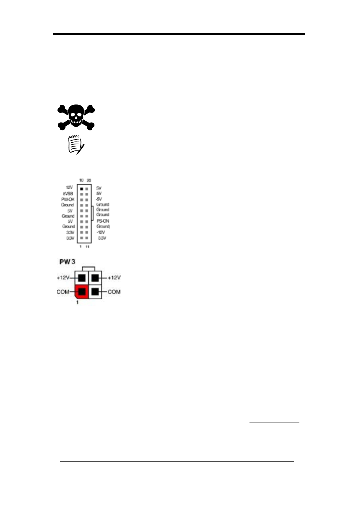
Chapter 2
2-28 Установки соединителей и перемычек
Соединители используются, чтобы соединять системную плату с другими
частями системы, включая блок питания, клавиатуру и различные контроллеры
на передней панели системного блока.
Соединитель электропитания – это самое последнее подключение,
которое будет проделано при монтаже системной платы. Перед
подключением блока питания, пожалуйста, удостоверьтесь в том, что
он не подсоединен к электрической сети.
Все кабели, поставляемые фирмой CHAINTECH, снабжены
устройствами безопасности.
PW 1 / 3 (Соединитель блока питания ATX):
Шнур питания, соединяющий блок питания системы с
внешним источником питания, следует подключать в
самую последнюю очередь. Блок питания ATX снабжен
единственным 20-контактным соединителем, который
обеспечивает подачу напряжений: стандартные +/-5В,
+/-12В, дополнительное 3,3В и сигналы программного
управления питанием. Сигнал программного управления
(Soft power signal), - это маломощный источник
напряжения 5В, которое всегда имеется при наличии
напряжения сети переменного тока. Когда система
находится в режиме «отключения по программе»
(Soft-Off mode), этот маломощный источник
поддерживает систему в состоянии потребления
минимальной мощности.
Блок питания AT X 12В снабжен новыми
дополнительными соединителями с сигналами +12В
(4-контактный) и +5В / 3,3В (6- контактный) для подачи
к системной плате напряжений постоянного тока +12В и +
5 / 3,3В.
Включение питания посредством модема:
Если система находится в состоянии отключения по программе (Soft-Off state)
и если модем получает извне сигнал пробуждения, то система будет
активирована и, таким образом, к ней возможен доступ на расстоянии. Вы
можете задействовать эту функцию в меню BIOS «Настройка управления
питанием» (Power Management Setup). (См. Раздел 3-57)
Мигающий индикатор в режиме временного отключения (Suspend
Mode):
Когда система находится в «спящем» режиме (Suspend mode), на передней
панели вашего компьютера будет мигать световой индикатор. Переход в
спящий режим производится нажатием зеленой кнопки Override Power
(отключение питания) на корпусе вашего ATX, или активацией команд Power
Management (управление питанием) и Suspend Mode (спящий режим) в меню
BIOS: Power Management (Управление питанием). (См. Раздел 3-57)
56
Page 65
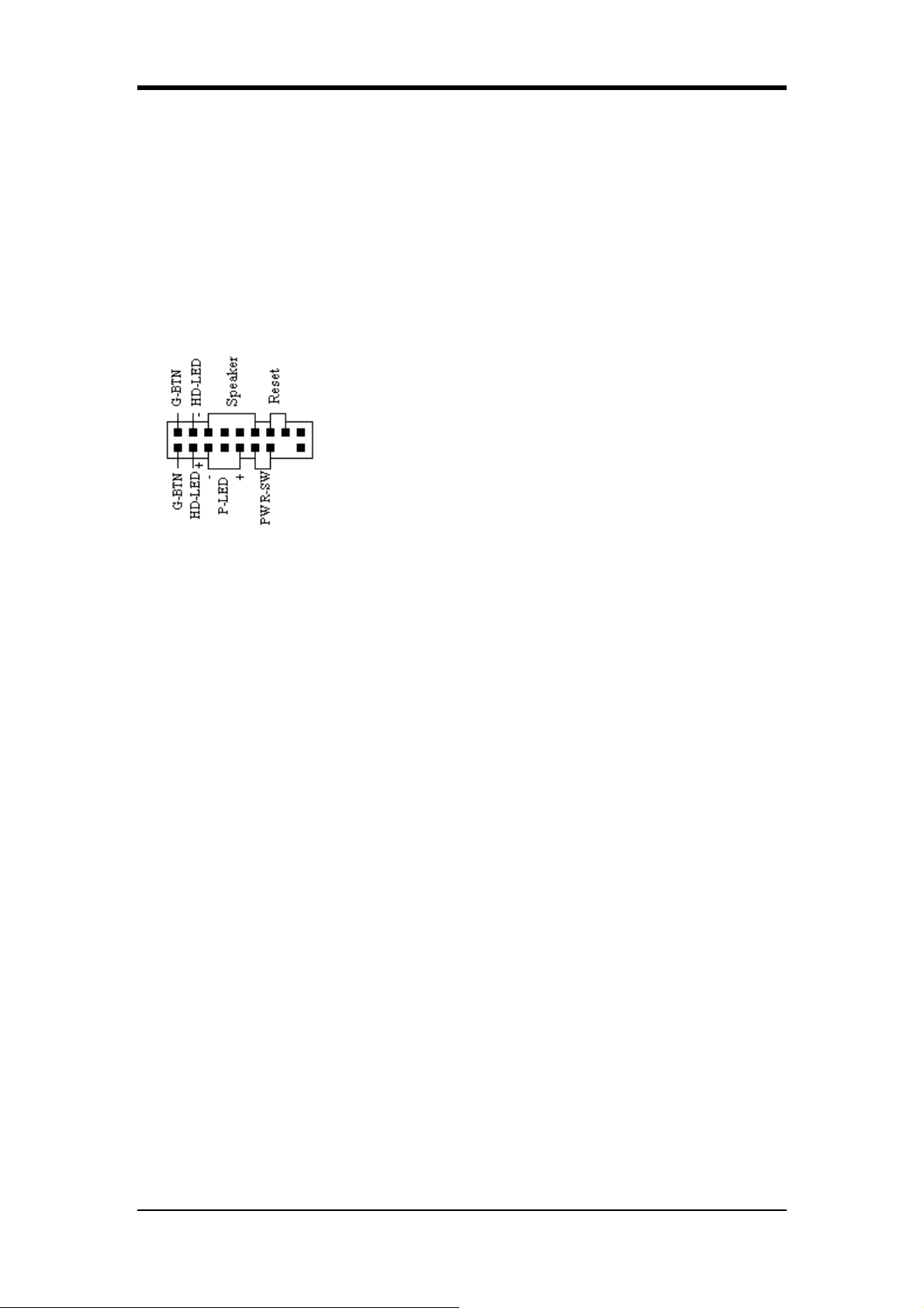
Chapter 2
Многократный предохранитель для защиты от перенапряжения:
Многократный предохранитель (poly-fuse) защищает систему от опасных
перенапряжений, которые могут проникать через клавиатуру или соединители
USB. В случае такого воздействия, многократный предохранитель немедленно
отключит систему от сети, подобно обычной плавкой вставке. После
отключения на некоторое время, многократный предохранитель вернется в
свое исходное состояние, и клавиатура или соединитель USB может вновь
работать. В отличие от обычных плавких вставок, многократный
предохранитель не требует замены, избавляя пользователя от таких неудобств.
CN1A (Соединитель передней панели):
PWR-SW (Соединитель кнопки отключения
питания (Over-ride Power)):
Кнопка силового питания на корпусе ATX может
быть использована как обычный выключатель
питания, но и в то же самое время для активации
продвинутого управления питанием в спящем
режиме (Advanced Power Management Suspend mode).
Это режим экономии энергии, включаемый тогда,
когда компьютер долгое время не используется. Для
активизации этой функции нужно настроить
программное отключение (Soft-OFF) с установкой
задержки на 4 секунды [Delay 4 Sec.] в функции PWR-BTTN в меню BIOS:
Настройка управления питанием (Power Management Setup).
Когда в функции PWR-BTTN задействована команда «программного
отключения» (Soft-OFF), нажатие на кнопку питания быстро переведет
систему в спящий режим (Suspend mode). Любое внешнее воздействие,
например: нажатие на любую из клавиш клавиатуры или перемещение мыши –
будет возвращать систему в прежнее, активное состояние (Full-On). Если же
длительность нажатия на кнопку в режиме Full-On превысит [4 секунды],
система будет выключена полностью. См. временную диаграмму срабатывания
кнопки «отключение питания» (Over-ride Power Button).
P-LED (Соединитель индикатора питания):
СИД индикатора питания показывает состояние питания системы. Важно
соблюдать правильную ориентацию разъемов кабеля при их подключении
(чтобы не перепутать положение этих двух соединителей).
G-BTN (зеленая кнопка выключения):
На некоторых корпусах ATX устанавливается зеленая кнопка выключения,
используемая для перевода системы в спящий режим (Suspend mode). В
спящем режиме потребляемая системой мощность резко снижается, генератор
ЦП отключается и ядро ЦП переходит в режим минимальной мощности.
Система вновь возвращается в активное состояние при прикосновении к мыши
или клавиатуре. Система будет пробуждаться различными способами, как
показано на экране BIOS при настройке управления питанием (Power
Management Setup).
ПЕРЕЗАГРУЗКА (RESET) (Соединитель кнопки перезагрузки системы):
Этот соединитель должен быть подключен к кнопке перезагрузки на передней
панели системного блока. Кнопка перезагрузки позволяет Вам перезапустить
систему без отключения питания.
ДИНАМИК (SPEAKER) (Соединитель динамика):
Этот 4-контактный соединитель подключает динамики, установленные внутри
корпуса.
57
Page 66
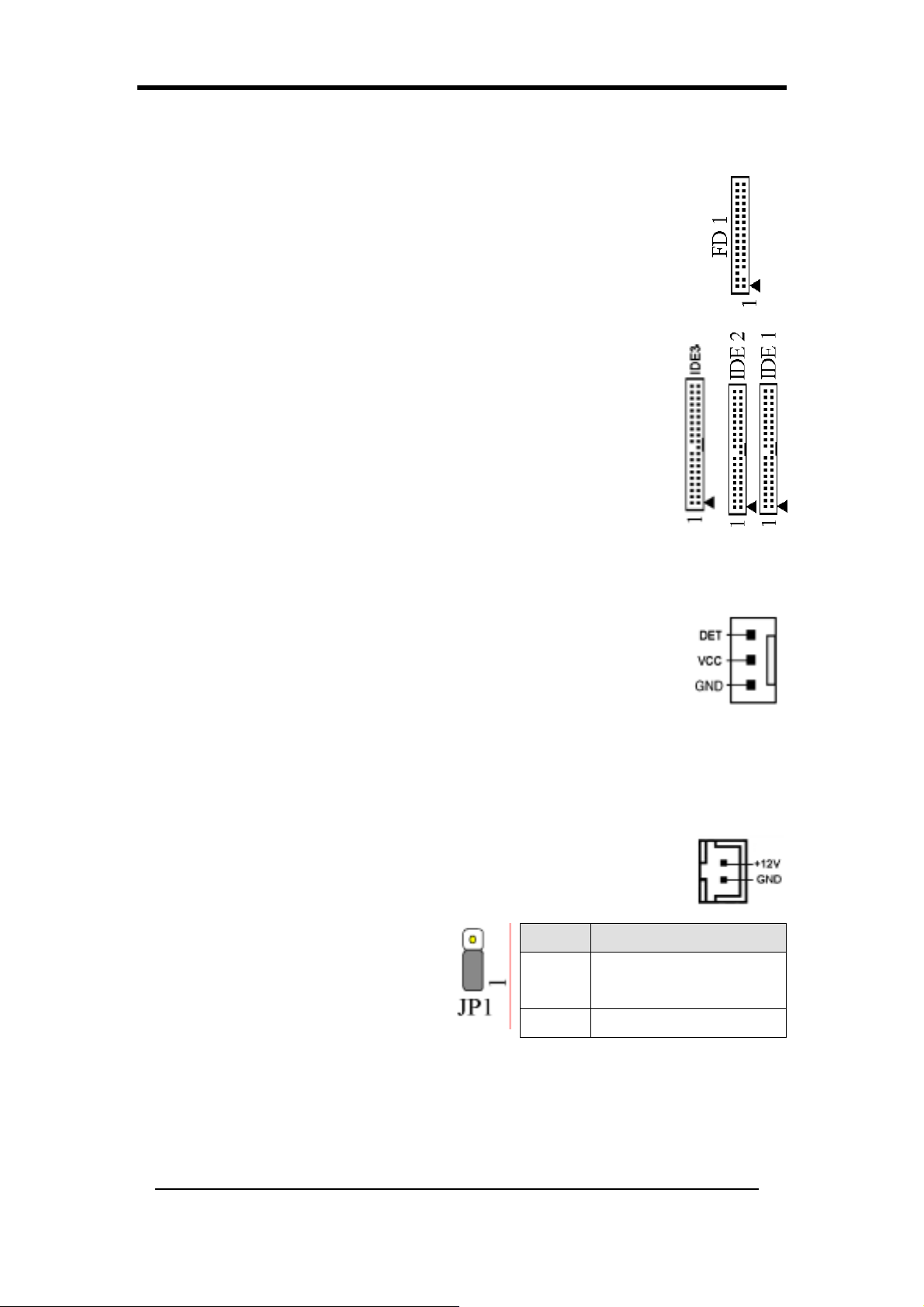
Chapter 2
СИД жесткого диска (HD-LED) (Соединитель индикатора ЖД):
СИД активности IDE-устройства загорается, когда система производит
запись/чтение с помощью устройств IDE.
FD1 (Соединитель флоппи-дисковода)
Системная плата имеет соединитель стандартного
флоппи-дисковода, который поддерживает флоппи-дисководы
360Кб, 720Кб, 1,2Мб, 1,44 Мб и 2,88 Мб. Флоппи-дисковод с 34
контактами подключается посредством этого соединителя.
IDE 1/2/3 (Соединитель жесткого диска IDE)
Эта системная плата имеет 32-битный Enhanced PCI IDE и
контроллер Ultra ATA66/100/133, обеспечивающий режим PIO
0~4, поддержку контроллера шины и функцию Ultra
ATA66/100/133. Этот соединитель используется для
подключения 40-контактных устройств ATA P I .
К IDE 1 подключается только два IDE-устройства. (Первичный
главный/подчиненный)
К IDE 2 подключается только два IDE-устройства. (Вторичный
главный/подчиненный)
К IDE 3 подключается только два IDE-устройства. (Tertiary
главный/подчиненный)
ВЕНТИЛЯТОР 1/2/3/4 (Соединители вентиляторов
ЦП/системы/ Case Fan/ Chip Fan Connectors):
Управление аппаратными средствами системной платы способно
оценивать число оборотов в минуту вентиляторов ЦП и
системного блока. Прокладка проводников и разъемы могут быть
различными, в зависимости от производителя. У стандартных
вентиляторов красный провод - это положительный вывод
(+12V), черный провод – это заземление и желтый провод – сигнал измерения
скорости. Подключайте вентилятор охлаждения северного моста к разъему
FAN4.
FAN 5 (Heat-Pipe Connector)
Этот разъем предназначен для подключения иепловой трубки к
материнской плате.
JP1 (Перемычка очистки CMOS):
На системной плате установлена
Клеммы Определение
память CMOS RAM с питанием от
внешнего элемента для сохранения
данных и конфигурации системы.
Для очистки содержимого CMOS,
1-2
2-3 Очистка данных CMOS
Нормально
(по умолчанию)
пожалуйста, выполняйте
нижеследующие шаги.
1.
Отсоедините от источника питания шнур силового питания.
2.
Установите колпачок перемычки на контакты [2-3] на <5 секунд> и
затем верните перемычку в исходное положение.
3.
Подсоедините питание к системе и запустите систему.
4. Запустите утилиту BIOS настройки CMOS (CMOS Setup) и выберите команду
‘Load Optimized Defaults’ (Загрузка настроек по умолчанию). Нажмите
58
Page 67
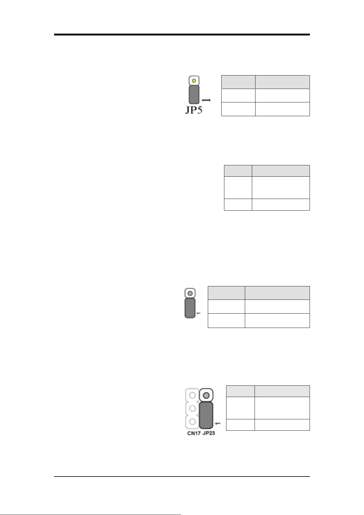
Chapter 2
клавишу [Y]
5.
В меню стандартной настройки CMOS (Standard CMOS Setup) настройте
и затем для продолжения нажмите клавишу [Enter].
конфигурацию системы.
JP5 (KB/MS Power On)
Питание этой системной платы
Клеммы Определение
может быть включено при помощи
клавиатуры PS / 2 (горячая клавиша).
Чтобы использовать эту функцию,
1-2 Отключено
2-3 Включено
выберите горячую клавишу по вашему
усмотрению в опции Hot (Запуск от PS/2) в подразделе Wake Up Events
(Запускающие события) на странице настройки BIOS: Power Management
Setup(Управление питанием). Чтобы использовать эту функцию, Вам также
следует установить эту перемычку на выводы [2-3].
JP6 (Power On by USB 2/3)
Эта системная плата может быть активизирована
посредством горячей клавиши USB или щелчком
мыши на USB. Чтобы воспользоваться этой
функцией, выберите на Ваше усмотрение горячую
клавишу для возобновления работы USB из
Клеммы Определение
Отключено
1-2
(по умолчанию)
2-3 Включено
варианта S3 в окне «Пробуждающие события» (Wake Up Events) на экране
BIOS «Управление включением питания» (Power On Management). Для
использования этой функции Вы также должны установить эту перемычку на
контакты 2-3.
JP6A/JP6D (Перемычка включения/отключения питания устройства
USB 4/5, 0/1)
JP6 USB 4/5 JP6A USB 0/1
Эта системная плата может быть
Клеммы Определение
активизирована посредством горячей
клавиши USB или щелчком мыши на
USB. Чтобы воспользоваться этой
функцией, выберите на Ваше усмотрение
1-2 Отключено
2-3 Включено
горячую клавишу для возобновления работы USB из варианта S3 в окне
«Пробуждающие события» (Wake Up Events) на экране BIOS «Управление
включением питания» (Power On Management). Для использования этой
функции Вы также должны установить эту перемычку на контакты 2-3.
JP23 (Светодиод зеленого свечения)
Эта перемычка предназначена для
настройки мигающего светодиода
зеленого свечения (дополнительно).
Вывод Определение
CHAINTECH
1-2
(по умолчанию)
2-3 OEM
59
Page 68
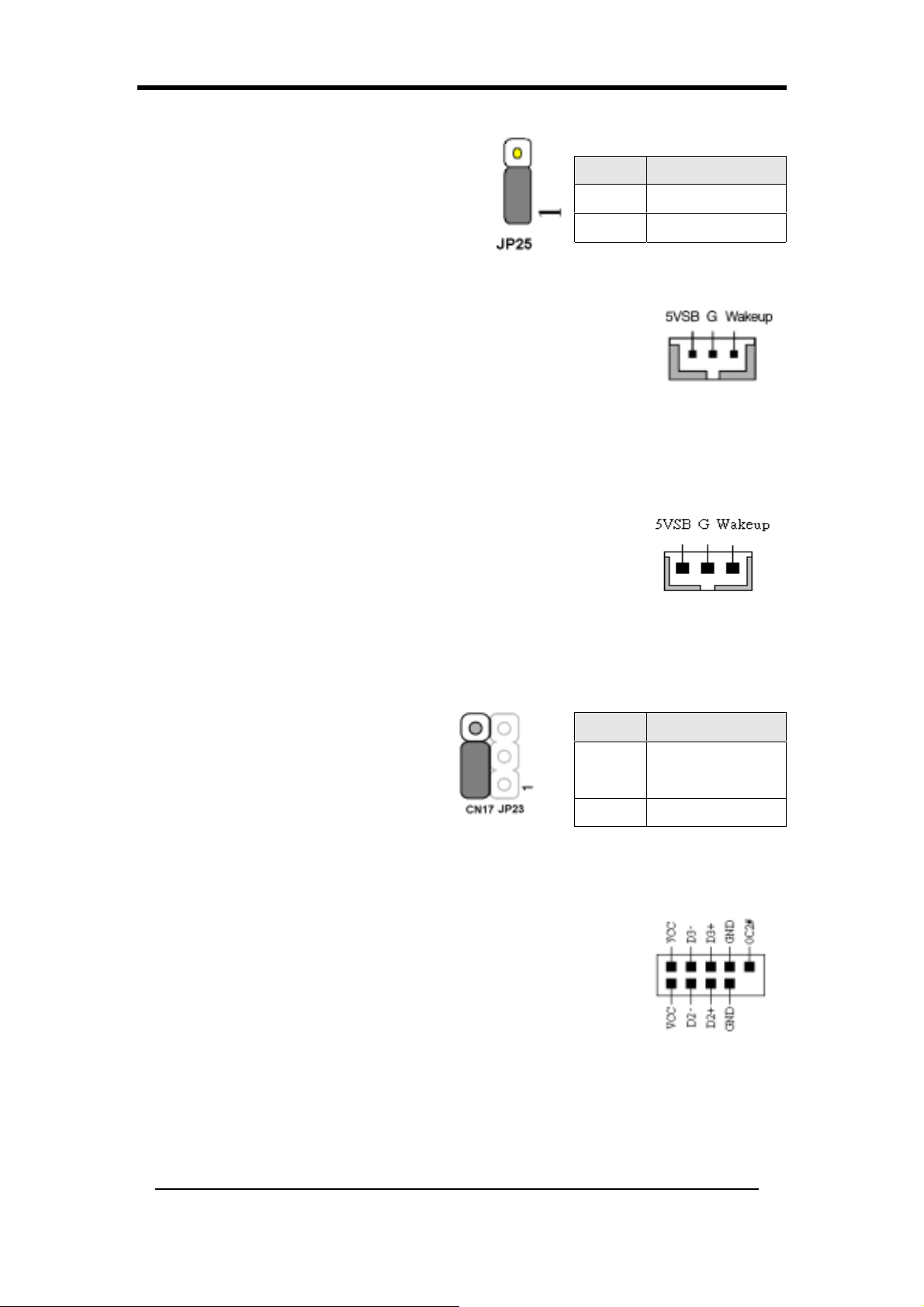
Chapter 2
JP25 (ROM Table Selct): Optional
Система переключается в режим User
Mode в процессе загрузки, если
джампер находится на контактах [1-2]. В
случае, если джампер находится на
контактах [2-3], система переходит в
Вывод Определение
1-2 User Mode
2-3 Safe Mode
Safe Mode.
CN5 [Соединитель WOL (пробуждение от сети LAN)]:
Активизируйте команду «Пробуждение от сети LAN» (Wake
Up On LAN) в меню BIOS «Управление питанием» (Power
Management). Возможность дистанционного управления
компьютерами по сетям – важный фактор снижения стоимости
оборудования и административных затрат. Для реализации
функции WOL у контроллера LAN разработана технология Magic Packet. Этот
разъем используется, чтобы подключить встраиваемое дополнительное
устройство NIC (Network Interface Card = сетевая интерфейсная карта),
позволяющее системной плате использовать функцию WOL.
CN5A [Соединитель WOM (пробуждение от
модема)]:
Активизируйте команду «Пробуждение от сети модема»
(Wake Up On Modem) ) в меню BIOS «Управление
питанием» (Power Management). Этот разъем
используется, чтобы подключить встраиваемую
дополнительную карту модема, позволяющую системной
плате использовать функцию WOM.
CN17 (Разъем светодиода синего свечения)
Функции этих индикаторов
аналогичны светодиоду наличия
питания, оба СИД показывают
состояние системного питания.
Отличие лишь в том, что один СИД
Вывод Определение
CHAINTECH
1-2
(по умолчанию)
синего свечения, а другой - красного.
2-3 OEM
CN23A/CN23B (Соединитель фронтального порта USB к панели для
USB 6/7 и 8/9): Optional
Порт USB 6/7 CN23A Порт USB 8/9 CN23B
Если Вы хотите использовать USB-клавиатуру, Вам
понадобится подключить функцию поддержки
USB-клавиатуры в меню BIOS «Интегрированные
периферийные устройства» (Integrated Peripherals) (См.
Раздел 3.4). Эта системная плата снабжена
хост-контроллером USB и разветвителем (root hub) с
двумя соединителями на устанавливаемом по заказу
адаптере USB (USB 6/7 и 8/9).
60
Page 69
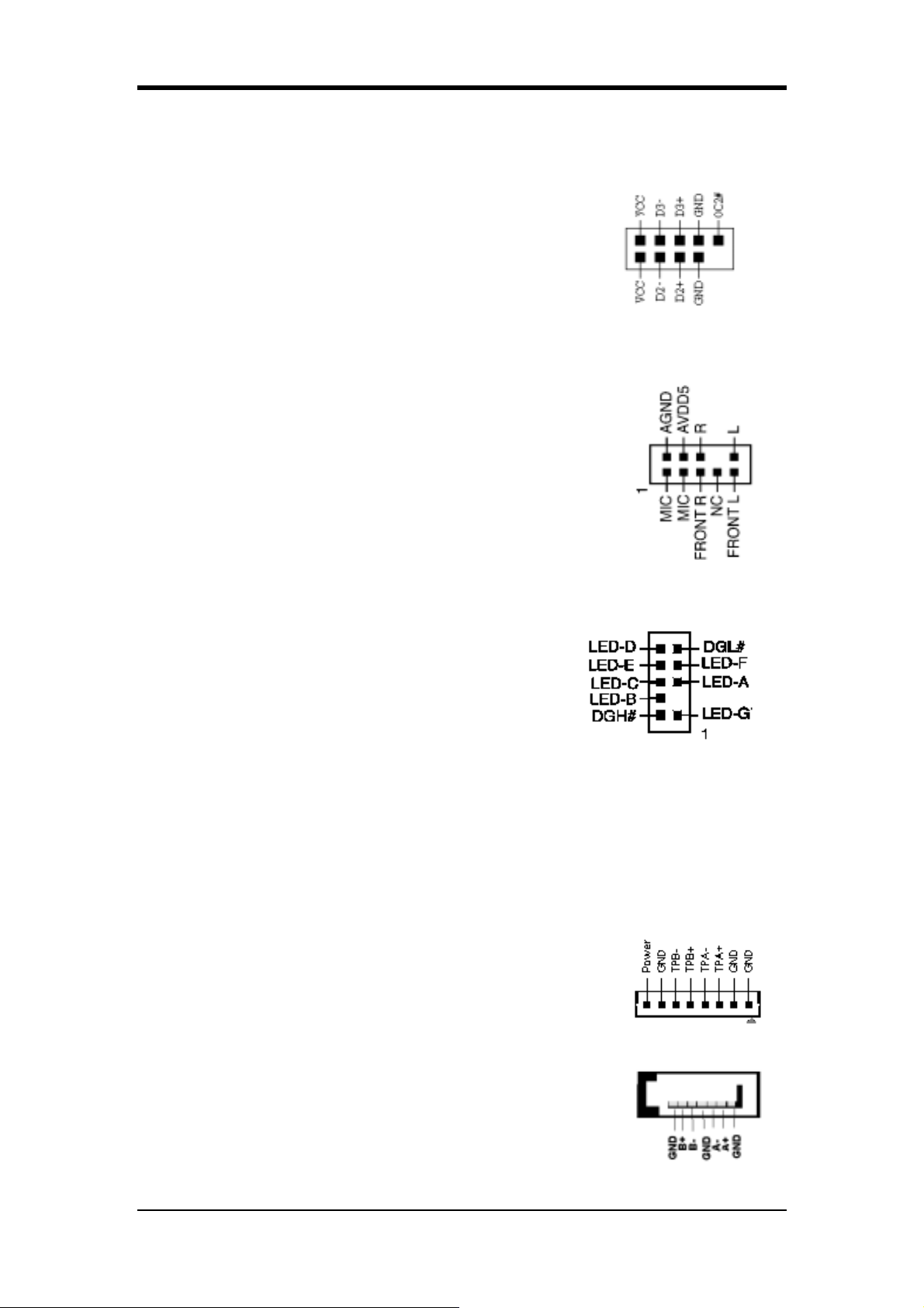
Chapter 2
CN23/CN23C (Соединитель фронтального порта USB к панели для USB
4/5 и 0/1):
Порт USB 4/5 CN23 Порт USB 6/7 CN23A
Если Вы хотите использовать USB-клавиатуру, Вам
понадобится подключить функцию поддержки
USB-клавиатуры в меню BIOS «Интегрированные
периферийные устройства» (Integrated Peripherals) (См.
Раздел 3.56). Эта системная плата снабжена
хост-контроллером USB и разветвителем (root hub) с
двумя соединителями на устанавливаемом по заказу
адаптере USB (USB 4/5 и 0/1).
CN24 (Разъем передней звуковой панели CBOX 3):
Этот соединитель предоставляет Вам возможность
подключения внешнего аудио-кабеля к фронтальному
разъему системного блока специального исполнения.
Просто удалите две перемычки с контактов [5-6] и [9-10],
затем подключите эти контакты к поставляемому по
заказу кабелю внешнего соединителя. По умолчанию
контакты [5-6] и [9-10] замкнуты накоротко, чтобы можно
было бы использовать аудио-панель сзади системного
блока.
CN25 (Соединитель дисплея диагностики DigiDoc панели CBOX™ 3):
Панель CBOX™ 3 включает усовершенствованный
диагностический дисплей DigiDoc фирмы
CHAINTECH, используемый для системного
мониторинга.
- 80-портовый дисплей диагностики для
показа процесса прохождения процедуры
POST при загрузке системы!
- Мониторинг температуры ЦП, Ваша система никогда не перегреется!
- DigiDoc – это врач для Вашей системы!
Более подробные сведения приведены в Приложении Digidoc 80-Port POST
Error Code List (Список кодов ошибок процедуры POST мониторинга
Digidoc).
CN26 (Соединитель порта контроллера IEEE 1394)
Подключите последовательный соединительный кабель
IEEE 1394 к разъему IEEE 1394 и к фронтальной панели
CBOX™ 3.
SATA 0/1/2/3 (Соединитель последовательного ATA):
Этот разъем позволяет подключить новое IDE-устройство;
поддерживается ATA 1 5 0 Мб/сек.
Пожалуйста, для получения дополнительных сведений
см.
61
Page 70
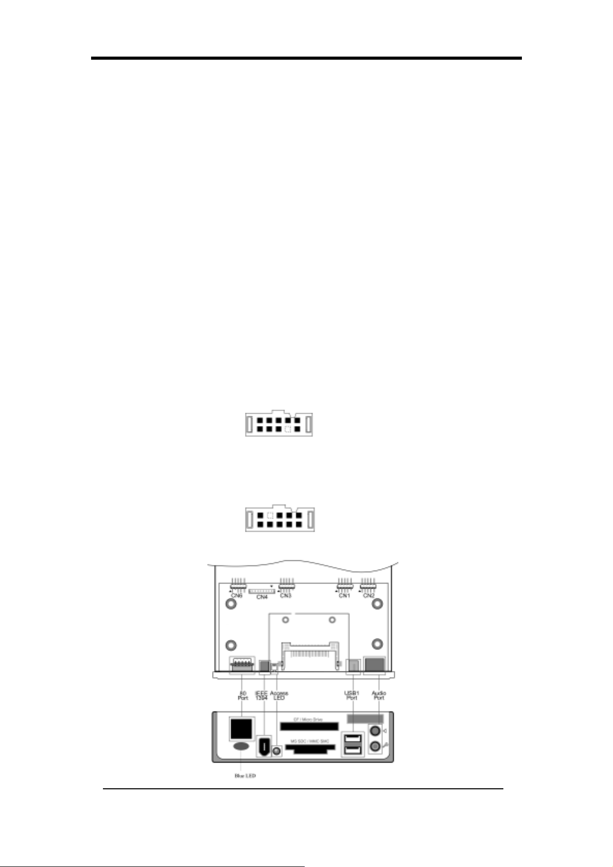
Chapter 2
2-29 Настройка панели CBOX™ 3
1.
Осторожно вставьте панель CBOX™ 3 в гнездо для обычного
флоппи-дисковода 5-1/4” в передней части системного блока и
надежно закрепите винтами по бокам.
2. Подсоедините системную плату к панели CBOX™ 3:
Функция Системная плата Панель CBOX™ 3
USB 4 & 5 CN23 CN1
USB 0 & 1 CN23C CN3
*Front Audio CN24 CN2
IEEE 1394 CN26 CN4
80 Port Display CN25 CN6
ВНИМАНИЕ: Для правильной работы CBOX3 пожалуйста совместите красную метку
аудио кабеля со стрелкой на разъёме CN2 и красную метку 80-штырькового кабеля
дисплея со стрелкой возле разъёма CN6.
* До установки удалите перемычки CN24 с контактов 5-6, 9-10 системной
платы.
Кабель USB (10 конт актов) x 2
Кабель фронтального аудио (10 контактов) x 1
IEEE-1394 Cable (8 контактов) x 1
Дисплей с портом 80 (10 контактов) x 1
62
Page 71
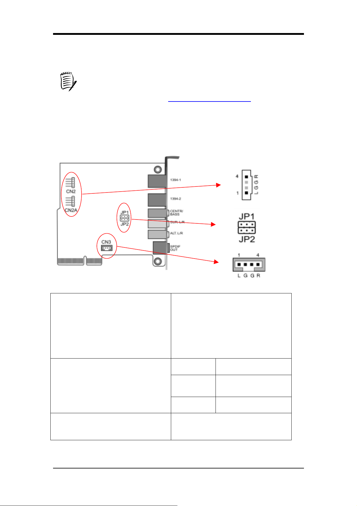
Если на дисплее CBOX2/CBOX3 после загрузки системы появляется код
ошибки “FF” – это НОРМАЛЬНО. Для того, чтобы на дисплее отображалась
температура процессора, пожалуйста, убедитесь в том, что APOGEE
Overclocking Utility или DigiDoc правильно установлена и выполняются.
Пожалуйста, обращайтесь на http://www.chaintech.com.tw
версиями APOGEE Overclocking Utility и DigiDoc.
2-30 Настройка CMC (Мультимедийная карта Chaintech)
Chapter 2
за последними
CN2/CN2A
(Соединитель встроенного аудио
CD-ROM)
JP1/JP2
(Подбор положений перемычек для
подключения Bass/Center)
CN3(Соединитель дополнительного
встроенного аудио устройства)
Используйте аудио кабель,
поставляемый с вашим приводом
CD-ROM, для подключения
CD-ROM к вашей системной плате.
Это позволит использовать звуковые
функции вашего CD-ROM.
Контакты Определение
1-2 Нормально
(по умолчанию)
2-3 Обмен
Этот соединитель предназначен для
аудио устройства AUX.
63
Page 72
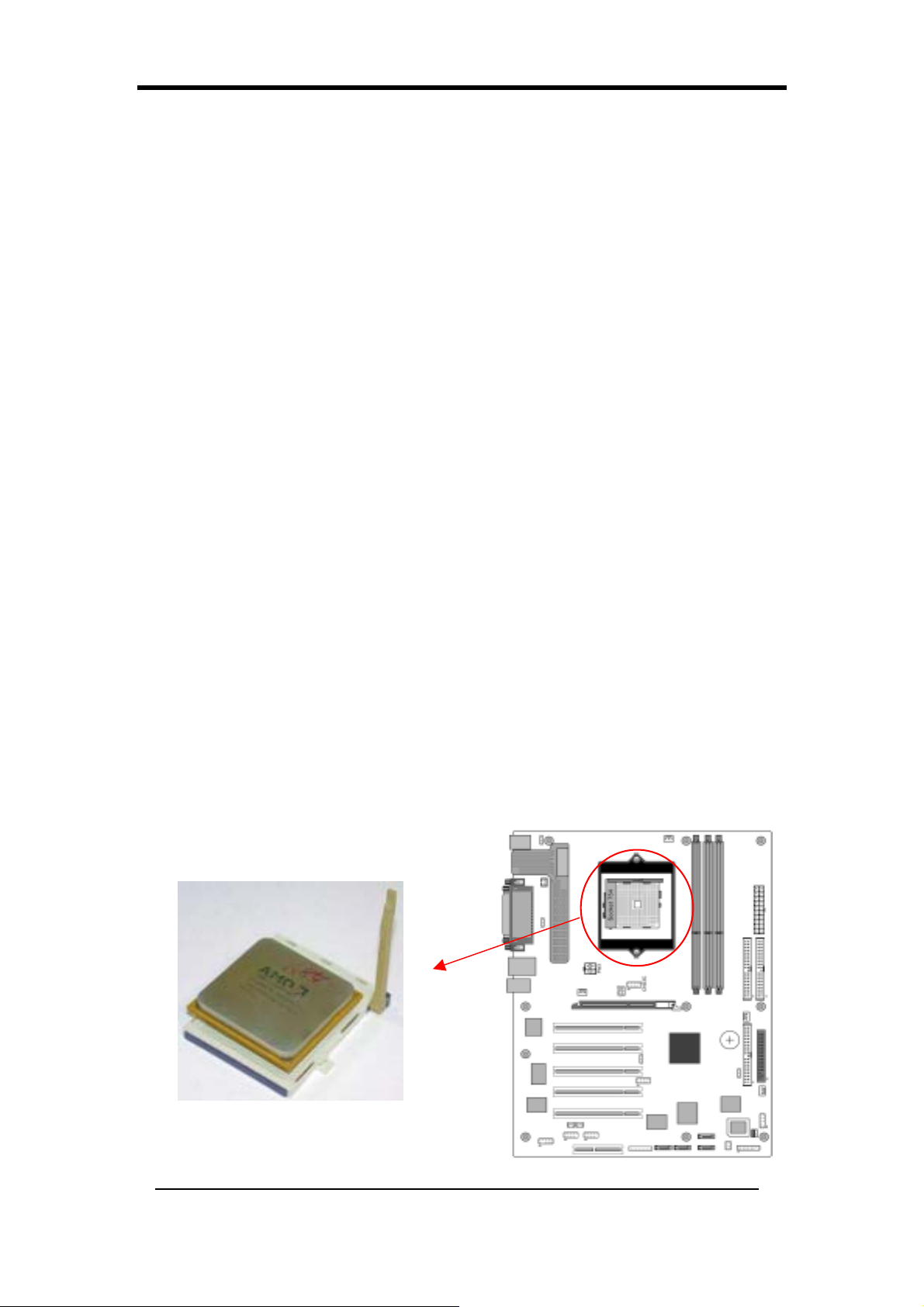
Chapter 2
하드웨어 설정 (Korean)
메인보드가 이미 인스톨되어 있더라도 시스템 하드웨어를 업그레이드 시키려면 이 장을
참고 하시면 됩니다. 메인보드는 정전기에 민감하므로 안전하고 적당한 보호수단 없이 메
인보드를 만지는 일이 없어야 하며 메인보드에 부속을 장착하기 전에 파워 케이블을 연결
하여서는 안됩니다. 이로 인해 제품에 전기적 쇼크가 발생할 수 있으니 주의 하시기 바랍
니다.
2-31 CPU 설정
AMD Athlon 754 프로세서를 위해 디자인된 Socket 754 는 표준 메인보드 사양에 맞춰 제작
된 것이며 CPU 를 Socket 754 에 장착하고자 한다면 아래와 같은 방법으로 장착해 주십시
오.
1. CPU 를 Socket 에 장착하기 전에 CPU 의 한쪽 모서리 부분의 잘려진 부분과 Socket 한쪽
모서리 부분의 잘려진 부분이 서로 일치하도록 장착하여야 합니다. 이렇게 잘려진 부분
은 CPU 의 1번 핀의 위치를 표시한 것입니다.
2. CPU 를 메인보드에 고정시키기 위해 Socket 754 의 옆에 달려있는 레버를 손으로 당겨
눌러주십시오. 이때 CPU 1 번 핀 옆에 위치한 레버 고정 홈에 레버가 물려 빠지지 않도
록 해야 합니다. 만약 제대로 홈에 완전히 물리지 않아 레버가 고정되지 않으면 CPU 에
치명적인 문제가 초래될 수도 있으니 주의하시기 바랍니다. 또한 AMD 가 공인한 쿨러
를 장착해 주셔야 하며 여기에 장착하는 쿨러는 CPU 에서 발생되는 열을 효과적으로
분산시켜 CPU 를 냉각시키기 위한 역할을 합니다. CPU 에 쿨러가 느슨하게 장착되거나
쿨러를 장착하지 않는다면 CPU 에 열이 과도하게 발생하여 CPU 가 열에 의해 탈 수도
있으니 주의하시기 바랍니다.
주의 : CPU 를 장착하기 전에 AC 파워 스위치를 꺼주십시오.
64
Page 73
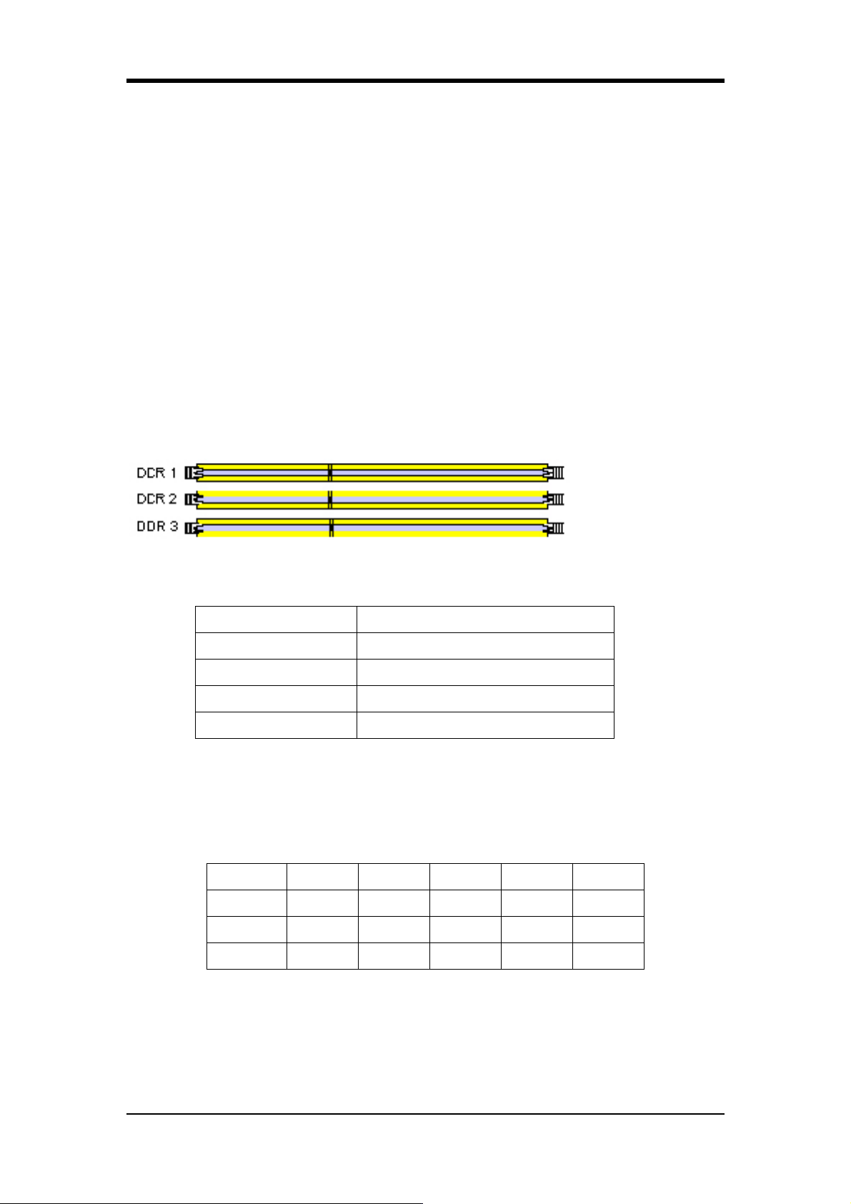
Chapter 2
2-32 CPU 점퍼 구성
CPU 의 FSB 에 따라 자동적으로 주파수가 설정됩니다.
2-33 주 메모리 구성
DDR SDRAM 메모리를 지원하는 3개의 램 슬롯을 지원합니다.
첫번째 램 슬롯에서는 최대 1GB 의 메모리를 지원하며, 또한 두번째, 세번째 램 슬롯
합하여 최대 1GB 의 메모리를 지원합니다. DRAM 사용시
DIMM1 + DIMM2 또는
DIMM1 +DIMM3 슬롯으로 구성하여 사용할 것을 권장합니다. DIMM2 + DIMM3
롯 사용시 시스템 안정성을 보장하지 못하며 권장하지 않습니다.
DDR SDRAM compatibility chart를
부록의
참고하십시오
.
DDR SDRAM 스펙
Memory Frequency Internal System BUS Frequency
100 MHz 200 MHz
133 MHz 266 MHz
166 MHz 333 MHz
슬
200 MHz 400 MHz
DIMM 타입 : 2.5V, 184 핀, 64/128/256/512 bit DDR SDRAM
모듈 크기 :
Single/double-sided 64/128/256/512MB/1GB
Parity : parity 이거나 non-parity 중 하나
DDR DRAM
Location 64 MB 128 MB 256 MB 512 MB 1.0 GB
DDR 1 X X X X X
DDR 2 X X X X X
DDR 3 X X X X X
지원에 대한 자세한 정보를 원하시면 첨부된 부록
(Appendix)을
참고하십시오
.
65
Page 74
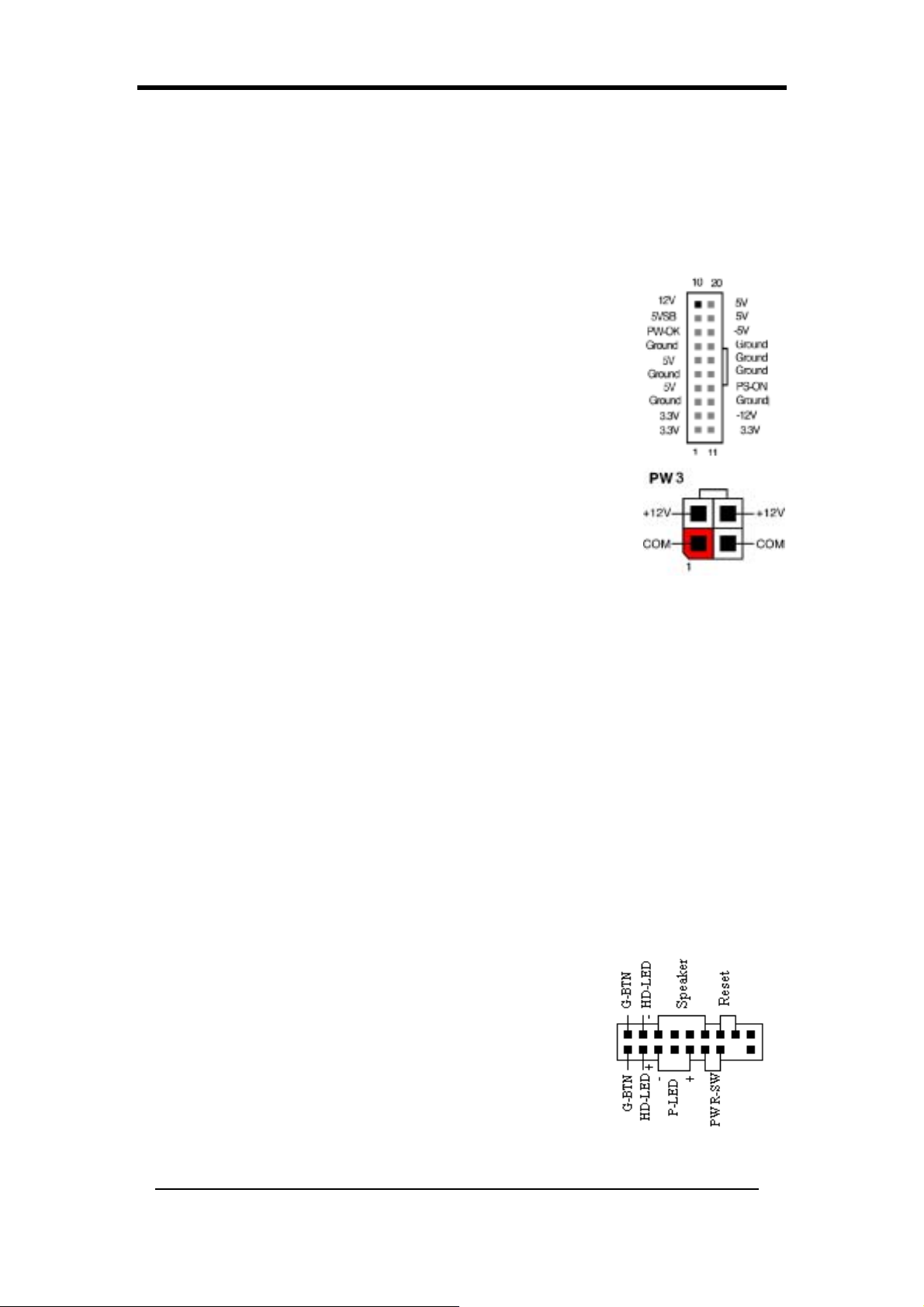
Chapter 2
2-34 커넥터 및 점퍼 셋팅
커넥터는 파워, 키보드 및 시스템 케이스 앞면의 여러 컨트롤러를 포함하여 시스템의 다른
부분과 함께 시스템 보드에 연결 됩니다.
PW 1 / 3 (ATX Power Supply Connector):
파워로부터 외부전원을 공급 받기 위한 파워코드는 시스템 조립을
할 때 제일 마지막에 연결해야 합니다. single 20 핀 커넥터 인터페이
스를 제공하는 AT X 파워는 기본 +/-5V, +/-12V, 추가 3.3V 및
Soft-Power 신호를 통합합니다. Soft-Power 신호 즉, a 5V 트릭클 공
급은 AC 파워가 이용 가능해질 때 지속적으로 공급되어 집니다.
시스템이 Soft-Off 모드에 있을 때 이 트릭클 공급은 최저 파워상태
에서 시스템을 유지합니다.
AT X 12 V 전원 공급 장치는 새로운 +12V (4-pin) 와 +5V/3.3V(6-pin) 의
예비 전원 커넥터를 가지고 있다. 메인보드에 추가적인 +12VDC 와
+5/3.3V VDC 전류를 공급 할 수 있다.
Power-On By Modem:
Soft-Off 상태에서 외부 모뎀에 신호가 발생되면 시스템이 구동됩니다. 사용자는 BIOS
Power Management Setup menu (3-70 참조)에서 이 기능을 활성화 시켜야 합니다.
대기모드에서 깜빡이는 LED
대기모드에서 사용자의 컴퓨터 프론트 패널 LED 는 깜박일 것이며, 대기모드는 Override
Power Button 을 누르거나 사용자의 ATX 케이스의 그린 버튼을 누름으로써 혹은 BIOS
Power Management menu(3-70 참조)의 대기모드 옵션과 Power Management 를 활성화 시킴으
로써 들어갈 수 있습니다
폴리퓨즈 과전류 방지
폴리퓨즈는 키보드나 USB 커넥터를 통하여 노출되어질 수 있는 시스템을 전압의 위험으
로부터 보호합니다. 그러한 노출의 경우 폴리퓨즈는 회로로부터 일반적인 퓨즈처럼 곧바
로 분리 될 것이며 일정시간 경과 후에 폴리퓨즈는 정상으로 돌아올 것입니 다. 그러면 키
보드나 USB 커넥터는 올바르게 다시 작동할 것입니다.
CN1A (Front Panel Connector)
PWR-SW (Over-ride Power Button 커넥터)
AT X 샤시에서 파워버튼은 Advanced Power Management
Suspend mode 를 촉진시키는 장치임과 동시에 표준 파워스위
치로도 이용됩니다. 이 모드는 컴퓨터를 장시간 사용하지 않
았을 때 전기를 절약하는데 이용됩니다. BIOS’s Power
Management Setup 메뉴에서 PWR-BTTN 기능에 의한
Soft-OFF 는 이 기능을 활성화하기 위해 [Delay 4Sec.] 로 설정
66
Page 75

Chapter 2
되어야 합니다.
PWR-BTTN 기능에 의한 Soft-OFF 가 가능해 질 때 파워버튼을 빠르게 누르면 대기모드로
시스템이 전환될 것입니다. 외부적인 어떤 물리적 활동, 즉 이를 테면 키보드의 키를 누르
거나 마우스를 움직이면 시스템은 다시 원 상태로 돌아올 것입니다. 또한 4 초 이상 풀 모
드에서 파워버튼을 누르고 있으면 시스템은 완전히 꺼지게 될 것입니다. Over-ride Power
Button Operation 도표를 참고하십시오.
P-LED (Power LED 커넥터)
파워 LED 는 시스템의 파워 상태를 보여줍니다. 핀과 케이블을 정확하게 맞추어 연결하는
것이 중요하며 이 두개의 커넥터 순서를 바꿔 연결하면 않되므로 주의를 요합니다
G-BTN (Green Button Switch)
대기모드로 시스템이 적용될 수 있도록 몇몇 AT X 케이스는 그린 버튼 스위치를 제공합니
다. 대기모드에서 시스템 파워는 전류의 흐름을 감소시키면 CPU 클럭은 멈추어지고 CPU
코어는 최저 파워 상태가 됩니다. 또한 시스템은 키보드나 마우스를 클릭하거나 움직이면
언제든지 깨어나게 됩니다. 시스템은 BIOS 에서 Power Management Setup 화면에 나와있는
바와 같이 다른 방법으로 회복되어 집니다.
RESET (System Reset Switch 커넥터)
이 커넥터는 시스템 케이스의 프론트 패널의 재부팅 스위치와 연결되어야 합니다. 재부팅
스위치는 전원 차단의 과정을 거치지 않고 시스템을 재 시작할 수 있습니다.
SPEAKER (Speaker Connector)
이 4핀 커넥터는 케이스에 설치된 스피커와 연결합니다.
HD-LED (IDE - Activity LED Connector)
IDE 는 IDE 디바이스에서 시스템을 읽거나 쓸 때 LED 가 켜짐으로써 활성화 됩니다.
FD1 (Floppy 커넥터)
이 메인보드는 표준 플로피 디스크 드라이버 연결(360K, 720K, 1.2M, 1.44M
and 2.88M floppy disk types)을 지원합니다. 이 커넥터는 34 핀 Floppy disk drive
에 연결하기 위한 것 입니다.
IDE 1/2/3 (IDE Hard-Disk 커넥터)
이 메인보드는 32-bit Enhanced PCI IDE 와 Ultra ATA66/100 제어(PIO mode
0~4, Bus Master, and Ultra ATA66/100) 기능을 지원합니다. 이 커넥터는 40 핀
ATA P I 디바이스를 연결하기 위한 것입니다.
IDE 1 은 두개의 IDE 디바이스와 연결합니다. (제 1 차 Master/Slave)
IDE 2 는 두개의 IDE 디바이스와 연결합니다. (제 2 차 Master/Slave)
IDE 3 는 두개의 IDE 디바이스와 연결합니다. (제 3 차 Master/Slave)
67
Page 76
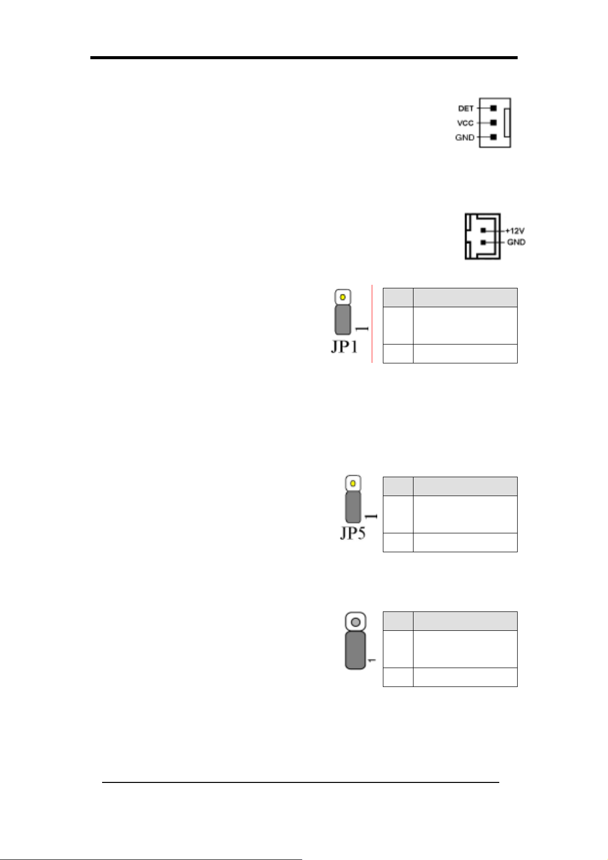
Chapter 2
FAN1/2/3/4 (CPU/System/ North Bridge Cooling Fan 커넥터)
보드의 관리확장 하드웨어는 CPU 와 시스템 팬의 RPM(Revolution Per
Minute) 속도를 발견할 수 있습니다. 배선 및 플러그는 제조사에 따라 틀립
니다. 표준 팬에서 빨강색은 +12V 이고 검정색은 접지이며 노랑색 배선은
회전 신호입니다. North Bridge 쿨링 팬의 배선 및 플러그는 제조사에 따라
틀립니다. 표준 팬에서 빨강색은 +12V 이고 검정색은 접지입니다.
FAN 5 (Heat-Pipe connector)
이 커넥터는 메인보드의 Heat-Pipe 에 이용되는 전원 커넥터입니다.
JP1 (CMOS Clear Jumper)
CMOS 항목을 클리어 하기 위해서는 아래의 방
법을 거쳐야 합니다.
1. 파워 전원을 차단합니다.
2. 점퍼 캡을 [2-3]에 놓고 5 초 정도 기다리
면 디폴트 상태가 됩니다.
Pin Definition
1-2
2-3 Clear CMOS Data
Normal
(default)
3. 시스템 파워를 연결하고 시스템을 시작합니다.
4. BIOS’s CMOS Setup Utility 에서 Load Setup Defaults 를 선택합니다. Type[Y] 로 설정하고
Enter 를 누릅니다.
5. Standard CMOS Setup 메뉴에서 시스템 구성을 설정합니다.
JP5 (KB/MS Power On)
이 보드는 PS/2 키보드(핫키)에 의해 켤 수 있습니
다. 이 기능을 이용하기 위해서는 BIOS’s Power
Pin Definition
Disable
1-2
Management Setup 화면에서 Wake Up 아래 PS2KB
Wakeup 옵션에서 핫키를 선택해야 합니다. 또한
이 기능을 위해서는 점퍼 캡을 [2-3]핀에 설정해야 합니다.
2-3 Enable
(default)
JP6 (Enable/Disable USB 2/3 Device Power ON Jumper)
USB 키보드 핫키 또는 USB 마우스 클릭으로 이
보드를 작동시킬 수 있습니다. 이 기능을 이용하기
위해서는 BIOS’s Power On Management 화면에서
Wake Up 아래 S3 옵션으로부터 USB Resume 의 핫
키를 선택해야 합니다. 또한 이 기능을 사용하기 위해서는 점
Pin Definition
Disable
1-2
(default)
2-3 Enable
퍼 캡을 2-3 번 핀에 설정해야 합니다.
68
Page 77
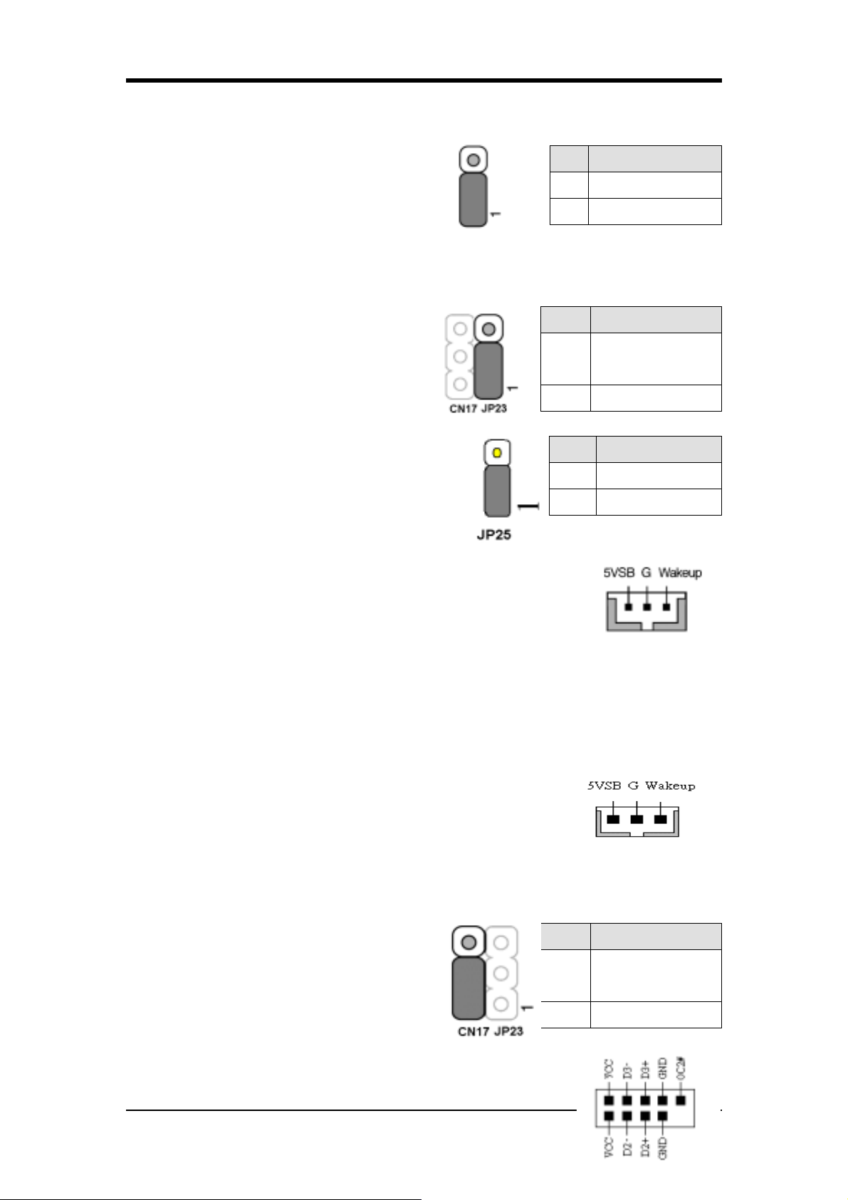
Chapter 2
JP6A/6D (Enable/Disable USB 4/5, 0/1 Device Power ON Jumper)
USB 키보드 핫키 또는 USB 마우스 클릭으로
이 보드를 작동시킬 수 있습니다. 이 기능을 이
용하기 위해서는 BIOS’s Power On Management
화면에서 Wake Up 아래 S3 옵션으로부터 USB
Resume 의 핫키를 선택해야 합니다. 또한 이 기능을 사용하기 위해서는 점퍼 캡을 2-3 번
핀에 설정해야 합니다.
Pin Definition
1-2 Disable
2-3 Enable
JP23 (그린 모드 LED)
캡은 그린 LED 플래쉬 모두를 설정하기 위
Pin Definition
Normal
1-2
한 것이다.(옵션)
2-3 Reserve
(default)
JP25 (ROM Table Selct): Optional
유저 모드로 시스템을 사용하기 위해서는 점퍼의
위치를 [1-2]로 설정해야 하며, 안전모드로 사용하
기 위해서는 점퍼를 [2-3]으로 설정해야 합니다.
Pin Definition
1-2 User Mode
2-3 Safe Mode
CN5 [WOL (Wake-on-LAN)]
이 기능을 이용하기 위해서는 BIOS’s Power Management 메뉴에서
Wake Up On LAN 을 선택 활성화해야 합니다. 네트웍크 상에서 PC 를
제어할 수 있는 기능은 관리와 소유비용을 감소시키는 중요한 요소
입니다. Magic Packet technology는 LAN 제어기에 WOL기능을 제공한다. 이 헤더는 메인보드
에서 WOL capability 를 제공하는 NIC(Network Interface Card)를 연결하는 데 이용되어 집니
다.
CN5A [WOM (Wake-on-Modem) 커넥터]
이 기능을 이용하기 위해서는 BIOS’s Power Management Menu 에서
Wake Up On Modem 을 선택 활성화 해야 합니다. 이 헤더는 메인보
드에서 WOM capability 를 제공하는 모뎀카드를 연결하는데 이용되
어 집니다.
CN17 (블루 LED 커넥터)
이들 특징은 전원표시기 LED 처럼 작동하며 시
스템의 전원상태를 보여 줍니다. 단지 하나는
파란색이고 다른 하나는 빨강색 LED 라는 점이
다릅니다.
CN23/CN23C (USB 4/5 와 0/1)
Pin Definition
Normal
1-2
(default)
2-3 Reserve
69
Page 78
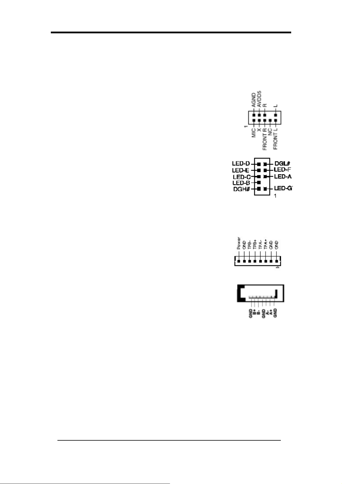
Chapter 2
USB Port 4/5 CN23 USB Port 0/1 CN23C
USB 키보드를 이용하고자 한다면 BIOS’s Integrated Peripherals 메뉴(3-69 장 참조)에서 USB
키보드 지원기능을 활성화시켜야 합니다. 이 보드는 USB 호스트 컨트롤러를 포함하며 추
가 USB 아답터를 위한 두개의 커넥터와 같이 루트허브를 포함합니다.
(USB 4/5 과 0/1).
CN24 (CBOX™ 3 Front Audio 커넥터)
이 커넥터는 시스템 케이스에 끼워진 프론트 패널 외부 오디오 잭 케이
블 옵션을 제공합니다. 두개의 점퍼 캡을 [5-6]번 핀과 [9-10]번 핀에 옮
겨 외부 케이블 커넥터(옵션)에 연결합니다. [5-6]핀과 [9-10]핀은 빽패널
오디오 기능을 활성화하면 디폴트 됩니다.
CN25 (CBOX™ 3 DigiDoc System Display 커넥터)
CBOX™ 3 의 특징 중에 포함되어 있는 CHAINTECH 의 DigiDoc 은
시스템을 진단하여 모니터 화면에서 보여줍니다.
80-PORT 는 시스템을 부팅할 때 POST 단계에서 진단내용을 보여
줍니다.
시스템이 항상 적정한 온도를 유지하도록 CPU 온도를 감시합니다.
DigiDoc 은 시스템을 위한 의사와 같습니다. (부록 Digidoc 80-Port POST Error Code List 를 참
고해 주십시오.)
CN26 (IEEE1394 커넥터)
CBOX™ 3 Front panel 과 IEEE1394 연결케이블로 연결하십시오.
SATA 0/1/2/3 (Serial ATA 커넥터)
이것은 새로운 IDE 디바이스에 연결할 수 있으며 ATA 150MB/sec
를 지원합니다.
70
Page 79
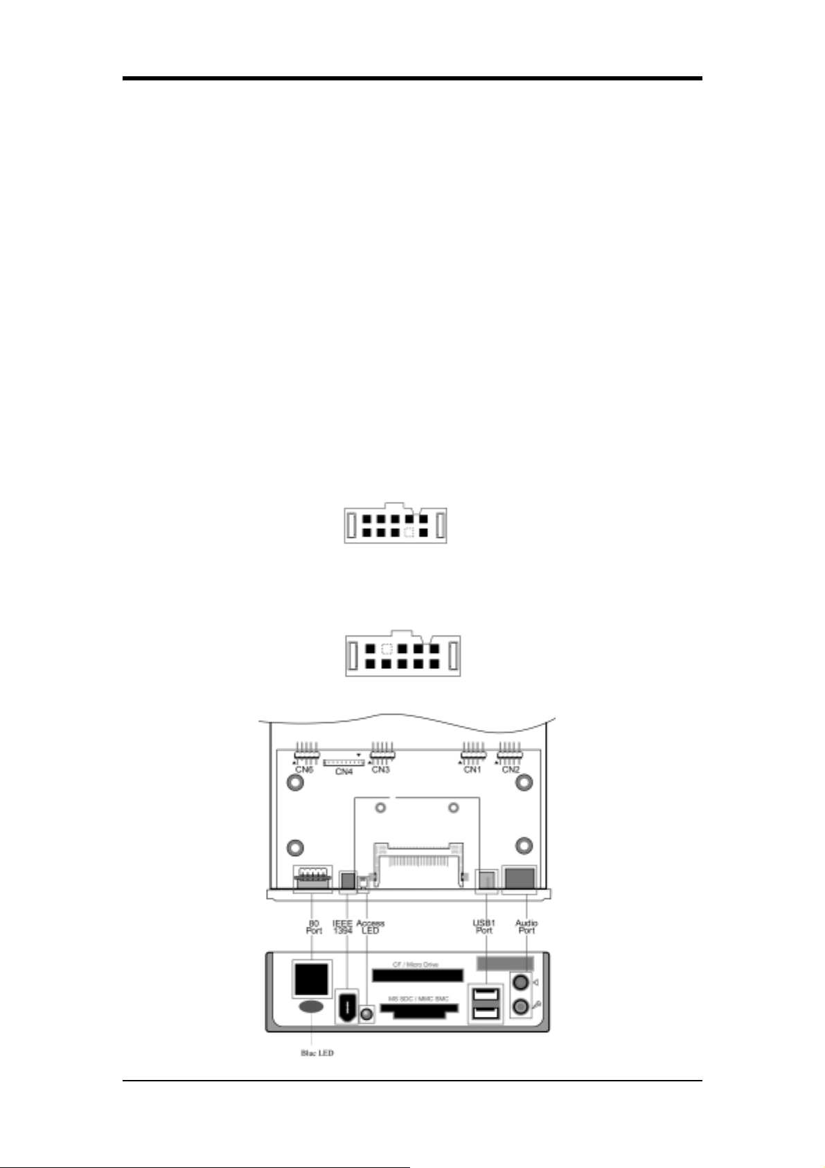
Chapter 2
2-35 CBOX™ 3 설정
CBOX™ 3 를 케이스 전면부 표준 5-1/4” drive bay 에 부드럽게 삽입하고 양 옆을 나사로
단단히 조여줍니다.
CBOX™ 3 와 메인보드를 다음과 같이 연결합니다.
Function Motherboard CBOX™ 3
USB 4 & 5 CN23 CN1
USB 0 & 1 CN23C CN3
*Front Audio CN24 CN2
IEEE 1394 CN26 CN4
80 Port Display CN25 CN6
: CBOX™ 3의
참조
Audio/80 port
* 연결 전에
올바른 설치를 위해
디스플레이 케이블들의 화살표 쪽을 일치하도록 연결해 주십시오
CN24 Jumper Caps (5-6, 9-10)
, 각 CN2와 CN6
을 제거 하십시요.
연결부의 화살표(굵은 선) 쪽과
USB Cable (10 pin) x 2
Front Audio Cable (10 pin) x 1
IEEE-1394 Cable (8 pin) x 1
80 Port Display (10 pin) x 1
.
71
Page 80
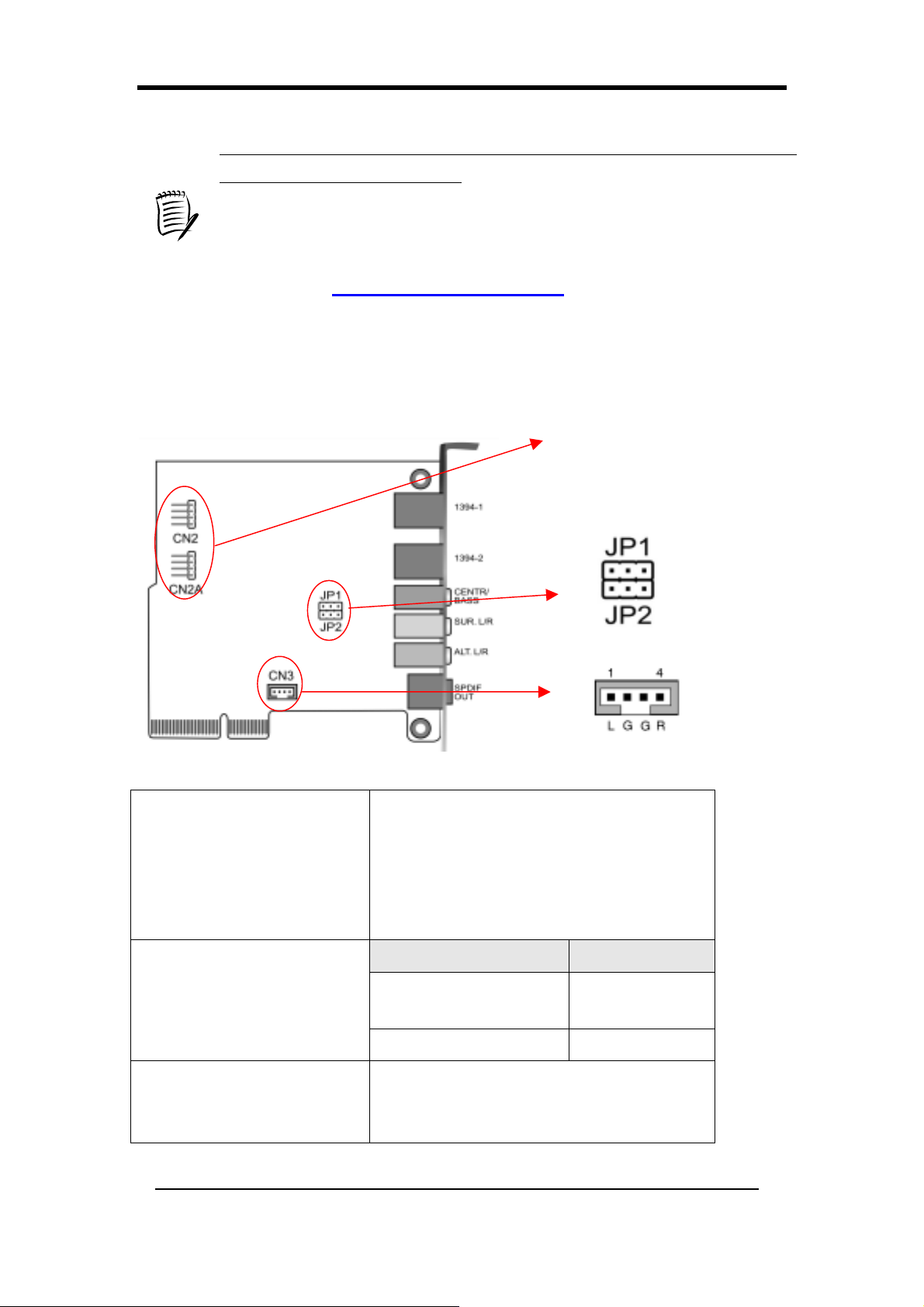
Chapter 2
컴퓨터가 부팅된 후
운영체제와 상관없이 정상입니다.
DigiDoc
나타낼 것 입니다.
최신 버젼의
본사 홈페이지
이 설치되어 동작할 때 만
Apogee Overclocking Utility
CBOX2, CBOX3 디스플레이 창에 “FF”라고 나오는 것은
다만 Apogee Overclocking Utillity 혹은
CBOX2, CBOX3
(http://www.chaintech.com.tw)
2-36 CMC (Chaintech Multimedia Card) 설정
가 현재의 CPU 온도를
DigiDoc
와
를 방문하여 주십시오.
을 원하시면 체인택
CN2/CN2A
(CD-ROM Audio-in 커넥
터)
JP1/JP2
(Bass/Center Select)
CN3
(Auxiliary Audio-In 커넥터)
메인보드에
CD-ROM 디스크 드라이브에 오디오 케이블이
연결되어야 합니다. 이것은
오 기능을 활성화 시 킬 것입니다.
CD-ROM
을 연결하기 위해서는
CD-ROM
의 오디
Pin Definition-
1-2 Normal
(Default)
2-3 Swap
이 커넥터는
입니다.
AUX Audio Device
를 위한 것
72
Page 81
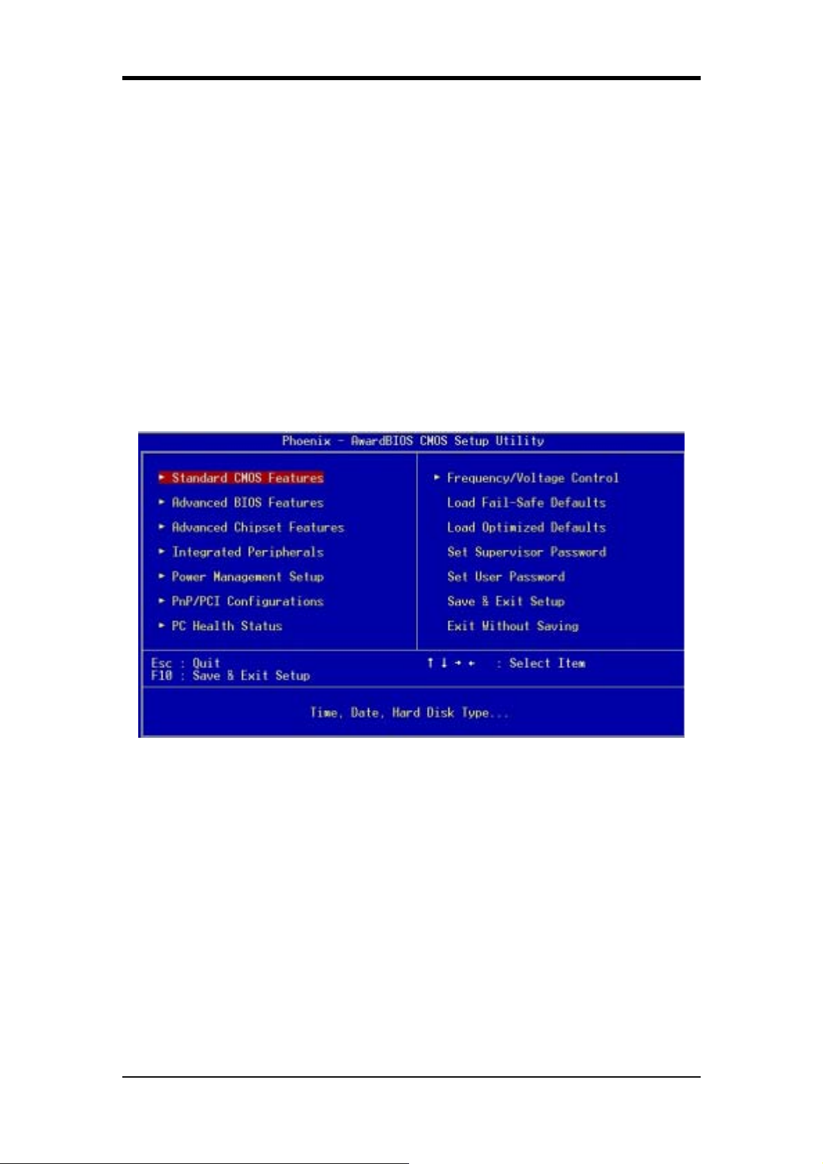
Chapter 3
Chapter 3 BIOS Setup Program
Phoenix-Award BIOS ROM has a built-in setup program that allows users to modify
the basic system configuration. This information is stored in CMOS RAM so that it
can retain the setup information even when the power is turned off.Press [Delete]
when you Power on or Reboot the computer system. (i.e. After Intel Pentium 4 logo
appears at the center of the screen, please press [Delete] to enter the BIOS setup
program).
The primary screen as shown in Figure 3-1 is a list of the menus and functions
available in the setup program. Select the desired item by using arrow keys and press
[Enter] to make the changes. Operating commands are located at the bottom of this
and all other BIOS screens. When a field is highlighted, on-line help information is
displayed on the right side of the screen.
Figure 3-1 Setup Program Initial Screen
73
Page 82
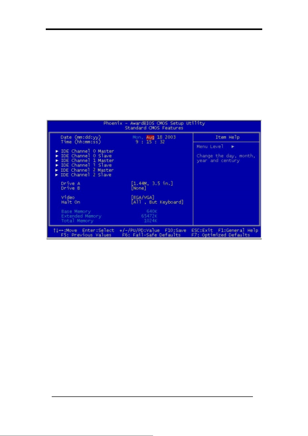
Chapter 3
3-1 Standard CMOS Setup
The Standard CMOS Setup allows users to configure system components such as
hard-disk drive, floppy-disk drive and video display as well as date, time and boot up
error signaling. This configuration menu should be changed when installing a
motherboard for the first time, or changing hardware such as HDD, FDD, and video
display in your system, or when the CMOS data was lost or corrupted. Choose the
Standard CMOS Setup option from the CMOS Setup Utility menu (Figure 3-1) to
display the following screen:
Figure 3-2 Standard CMOS Feature Screen
Date/Time:
Set the date and time of the system. Do not skip this function as all of your timed
events such as power management, saving files, etc are based on this timer.
IDE (Channel 0/1/2; Master/Slave):
This category identifies up to four IDE hard-disk drives that have been installed in the
computer. This section does not show information on other IDE devices such as
CD-ROM drives or other hard drive types such as SCSI drive.
Drive A/B:
Select different Floppy device Model. Available options are [None], [360K, 5-1/4 in],
[1.2M, 5-1/4 in], [720k, 3-1/2 in], [1.44M, 3-1/2 in], and [2.88M, 3-1/2 in].
Video:
Select the type of video adapter present in your system. You can ignore this setting if
you are using a VGA monitor; VGA BIOS will automatically configure this setting.
Halt On:
When the system is powered on, BIOS performs a series of diagnostic tests called
74
Page 83
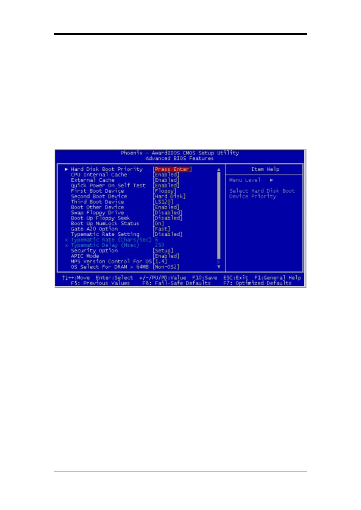
Chapter 3
POST (Power On Self Test). This function stops the computer if BIOS detects a
hardware error. You can tell BIOS to halt on all errors, no errors, or not to halt on
specific errors.
3-2 Advanced BIOS Features
By choosing the Advanced BIOS Features option from the CMOS Setup Utility menu
(Figure 3-1), the screen that lists the manufacturer's default values for the
motherboard is displayed below.
Figure 3-3 Advanced BIOS Feature Screen
Hard Disk Boot Priority:
Select priority of the hard disk boot-up device.
CPU Internal/External Cache :
Cache memory is much faster than conventional DRAM system memory. These fields
allow you to enable or disable the CPUs Level 1 built-in cache and Level 2 external
cache. Both settings are left as Enabled to significantly increase the performance of
your computer.
Quick Power On Self Test:
Enable this function to reduce the amount of time required to run the POST (Power
On Self Test). BIOS will save time by skipping some items during POST. It is
recommended that you disable this setting. Discovering a problem during boot up is
better than loosing data during your work.
75
Page 84

Chapter 3
First/Second/Third/Boot Other Device:
This option sets the sequence of drives BIOS attempts to boot from after POST
completes. BIOS will search these drives for an operating system.
Swap Floppy Drive:
Enabling this function will swap the floppy drive assignment so that drive A will
function as drive B, and drive B will function as drive A. Note that the boot sequence
assignment mentioned directly above does not include booting from floppy drive B.
This function is useful if floppy drives B and A are of different types of drives and
you want to boot from floppy drive B.
Boot up Floppy Seek:
This is a set up check for floppy power-on after starting the computer system.
Boot Up NumLock Status:
This function defines the keyboard's number pad as number keys or arrow keys. If it is
set at On the number keys will be activated, if it is set at Off the arrow keys will be
activated.
Gate A20 Option:
This allows you to set the Gate A20 status. When set to [Fast], Gate A20 is cont
rolled by chipset. When set to [Normal], Gate A20 is cont rolled by a specific pin
from the keyboard controller. Available options are [Fast] and [Normal].
Keyboard Interface:
1.Typematic Rate Setting
When enabled, you can set the following two-typematic control items. When
disabled, the keyboard controller determines keystrokes arbitrarily in your
system.
2.Typematic Rate (Chars/Sec)
The typematic rate sets the rate at which characters on the screen repeat when a
key is pressed and held down.
3.Typematic Delay (Msec)
The typematic delay sets how long after you press a key that a character begins
repeating.
Security Option:
The Supervisor and/or User Password functions shown in Figure 3-1 must be set to
take advantage of this function. See Section 3.11 for password setting information.
When the Security Option is set to System, a password must be entered to boot up the
system or enter the BIOS setup program. When the Security Option is set to Setup, a
76
Page 85

Chapter 3
password is required to enter the BIOS setup program.
APIC Mode:
In order to comply with PC2001 standard, the system is designed to run in APIC
(Advanced Programmable Interrupt Controller) mode. Enabling APIC mode will
increase the available IRQ resources for the system. Available options are [Enabled]
and [Disabled].
MPS Version Control For OS:
This item allows you to select which MPS (Multi-Processor Specification) version is
used for the operating system. You need to select the MPS version that is supported by
your operating system. To find out which version to use, consult the vendor of your
operating system. Available options are [1.4] and [1.1].
OS Select (For DRAM >64MB):
If your system's DRAM is larger than 64MB and you are running OS/2, select OS/2 as
the item value. Otherwise, set the item value to Non-OS/2 for all other operating
systems.
Small Logo (EPA) Show:
This setup allows photo that is EPA.Logo.
77
Page 86
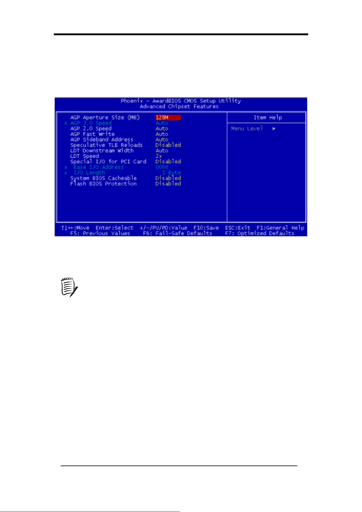
Chapter 3
3-3 Advanced Chipset Features
By choosing the [Advanced Chipset Features] option from the CMOS Setup Utility
menu (Figure 3-1), the screen that lists the manufacturer's default values for the
motherboard is displayed below.
Figure 3-4 Advanced Chipset Features
All of the above settings have been determined by the motherboard
manufacturer and should not be changed unless you are absolutely sure of
what you are doing. Explanations of the DRAM timing and chipset features
setup are lengthy, highly technical and beyond the scope of this manual. Below
are some brief descriptions of the functions in the Setup menu.
AGP Aperture Size (MB):
This function determines the amount of system memory that is given to the AGP card.
Available options ranges from 32MB to 512MB. This is a dynamic memory
allocation in that the AGP card will only use the amount of memory that it needs. The
remaining unused memory is also available for system usage. For example, if 16MB
is allocated to the AGP card and the card only needs 8MB, the remaining 8MB will be
available for system usage.
AGP 3.0 Speed:
This setting is enabled if AGP 3.0 is detected by the system.
AGP 2.0 Speed:
This is for setting the AGP bus speed.Avalible options [Auto], [1x], [1x2x], [1x2x4x].
78
Page 87
Chapter 3
AGP Fast Write:
Select [Auto] to allow Fast Write Protocol for 8x/4x AGP to function.
PS: Not all AGP cards support fast write.Availabe options: [Auto], [Disabled].
AGP Sideband Address:
This function determines the bus address between AGP card and CPU.
Availabe options: [Auto], [Disabled].
Speculative TLB Reloads:
It is recommended to leave it in [Auto] for a stable system operation.Select [Enabled]
increases the system performance but will cause the system to become unstable.
Availabe options: [Disabled], [Enabled].
LDT Downstream Width:
This function determines the downstream width of the LDT bus of which connects
CPU and CK8 chip. Availabe options: [8 bits], [Auto].
LDT Speed:
This function determines the speed of the LDT bus.Availabe options: [1x], [2x],
[2.5x], [3x], [4x].
Special I/O for PCI card:
This function allocates specific address for specific PCI cards.
Availabe options: [Enabled], [Disabled].
Overclockability:
This motherboard is designed to support overclocking ability.
However, please make sure your peripherals are able to tolerate such
abnormal setting, while CPU clock speed is overclocked. Any
attempt to operate beyond product specifications is not
recommended. We are not responsible for damages or risks caused
by inadequate operation or settings beyond product specifications
.
System BIOS Cacheable:
Enabling this function allows caching of the system BIOS ROM at F0000h-FFFFFh,
which results in better system performance. However, if any program writes to this
memory area, a system error may result. It is advisable to leave it in default setting.
Caching the system BIOS results in better performance than shadowing the system
BIOS.
Flash BIOS Protection:
The motherboard manufacturer developed BIOS protection technology that protects
79
Page 88
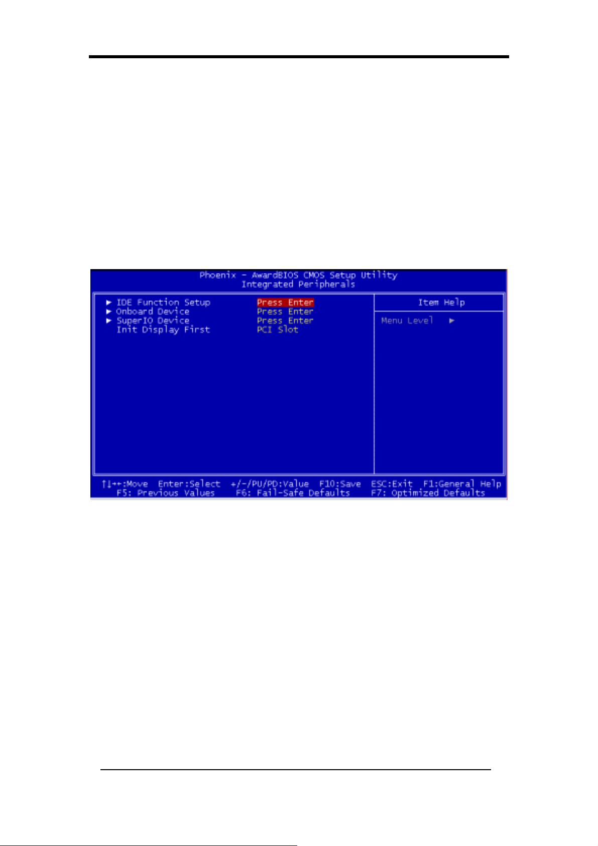
Chapter 3
the System BIOS from accidental corruption by unauthorized users or computer
viruses. When enabled, the BIOS data cannot be changed when attempting to update
BIOS with the FLASH utility. When disabled, the BIOS data can be updated by using
the FLASH utility.
3-4 Integrated Peripherals
This section provides information on setting up the peripheral devices. By choosing
the Integrated Peripherals option from the CMOS Setup Utility menu (Figure 3-1), the
screen that lists the manufacturer's default values for the motherboard is displayed
below.
Figure 3-5 Integrated Peripherals Screen
IDE Function Setup:
Press [Enter] to enter the sub-menu, which contains the following items for some
advanced control:
1. OnChip IDE channel 0/1
You can set this to disable the On Chip IDE controller if you are going to add
a higher performance IDE board.
2. Primary/Secondary Master/Slave PIO
The four IDE PIO (programmed Input/Output) fields let you set a PIO mode
(0-4) for each IDE device that the internal PCI IDE interface supports. Modes
0 through 4 provide successively increased performance. In Auto mode, the
system automatically determines the best mode for each device.
3. Primary/Secondary Master/Slave UDMA
Ultra DMA implementation is possible only if your IDE device supports it and
80
Page 89

Chapter 3
your operating environment contains a DMA driver. If both your hard drive
and software support Ultra DMA, select [Auto] to enable BIOS support.
4. Onchip IDE Channel 2
Avaliable Options: [Enabled], [Disabled].
5. IDE Prefetch Mode
The onboard IDE drive interfaces support prefetching for faster drive accesses.
Set to [Disabled] if this primary or secondary.
IDE DMA transfer access
6.
Avaliable Options: [Enabled], [Disabled].
7. IDE HDD Block Mode
Block mode is also called block transfer, multiple commands, or multiple
sector read/write. If your IDE hard-drive supports block mode, select Enabled
to auto-detect the optimal number of block read/writes per sector the drive can
support.
Onboard Device:
This section provides information for setting the on-board devices. Press [Enter] to
enter the sub-menu, which contains the following items for some advanced controls:
1. OnChip USB
Enable the on-board Universal Serial Bus (USB V1.1 or V2.0) controller if
you want to connect a USB device to your system. Note that if this setting is
disabled, you can still temporarily use a USB keyboard during boot up so that
you can enter BIOS and enable this setting. If you pass the boot up stage
without enabling this function, your USB keyboard will no longer work.
2. USB Keyboard Support
Select Enabled if your system uses an USB keyboard. If there is no USB
keyboard, select Disabled in this field.
Super IO Device:
This section provides information on setting the Super I/O devices. Press [Enter] to
enter the sub-menu, which contains the following items for some advanced controls:
1. Onboard FDC Controller
In order to use it select as Enabled if your system has a floppy-disk controller
(FDC) installed on the system board. If you install an add-in FDC or the
system has no floppy drive, choose Disabled in this field.
2. Onboard Serial Port 1/2
Select an address and corresponding interrupt for the first and second serial
ports. Available options are [3F8/IRQ4], [2E8/IRQ3], [3E8/IRQ4],
[2F8/IRQ3], [Disabled], and [Auto].
81
Page 90

Chapter 3
3. UART Mode Select
This function allows you to select an operating mode for the second serial port.
(Normal RS-232C serial port / IRDA / SCR / ASKIR 0.57-MB/sec infrared
port).
4. UR2 Duplex Mode
Available options: [Half] and [Full].
4. Onboard Parallel Port
Select a logical LPT port address and the corresponding interrupt for the
physical parallel port.
5. Parallel Port Mode
Select an operating mode for the onboard parallel (printer) port. Select SPP
unless you are certain that your hardware and software support one of the
other available modes.
6. ECP Mode Use DMA
This item automatically specifies DMA channel 1 or 3 for the parallel port
when it is set to [EPP] or [ECP+EPP] mode.
7. Game Port Address
This item disables or assigns the address of the Game port. Available options
are [201] and [209].
8. Midi Port Address
This item disables or assigns the address of the Midi port. Available options
are [300] and [330].
9. Midi Port IRQ
This item specifies an IRQ for the Midi port.
10. Init Display First
This function allows user to choose between [Onboard / AGP] or [PCI Slot]
to initialize Display first.
82
Page 91
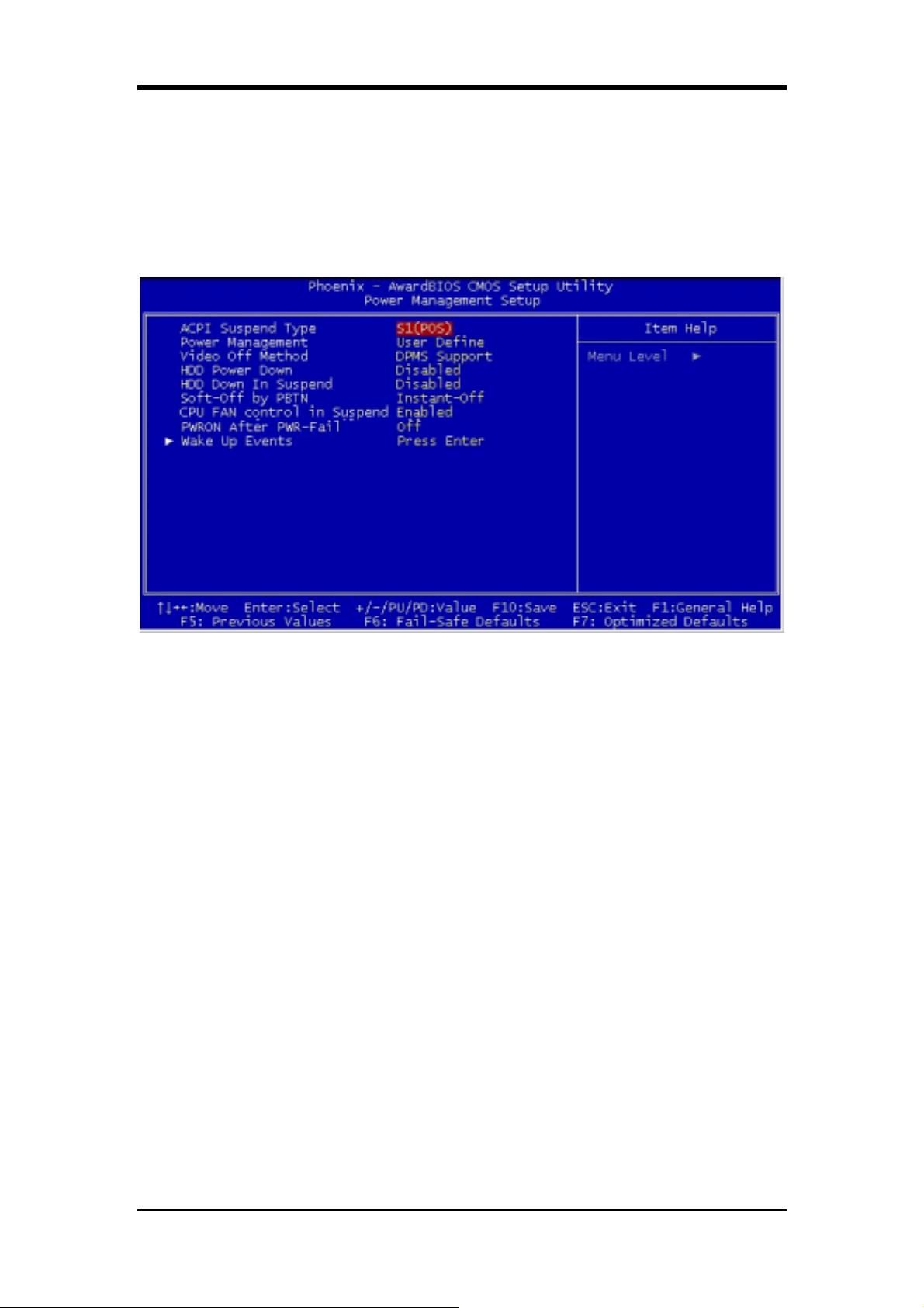
Chapter 3
3-5 Power Management Setup
This section provides information on the Green PC power management functions. By
choosing the Power Management Setup option from the CMOS Setup Utility menu
(Figure 3-1), the screen that lists the manufacturer's default values for the
motherboard is displayed below.
Figure 3-6 Power Management Setup
ACPI Suspend Type:
This item specifies the power saving modes for ACPI function. Available options are:
1. S1 (POS)
The S1 state is low power state. In this state, no system context (CPU or
Chipset) is lost and the hardware maintains all system contexts.
2. S3 (STR)
The S3 state is a lower power state, where the information of system
configuration and opened applications / files are saved to main memory. The
remaining power of other hardware components are turn off to save energy.
The information stored in memory will be used to restore the system when a
[wake up] event occurs.
3. S1 & S3
If S3 state is supported by the system, by default [S3] is automatically selected.
Otherwise [S1] is selected.
Power Management:
Power management saves electricity while the system is idle by entering
power-saving modes.
83
Page 92

Chapter 3
Video Off Method:
This function serves as both screen and power savers for the monitors. See the next
function, Video Off After, for setting the video timer.
1. Blank Screen - BIOS will switch the monitor screen to blank. The electricity
saved in this mode is negligible and this function is only used as a screen
saver to prevent screen damage while the screen is idle.
2. V/H SYNC+ Blank - The system turns off the vertical and horizontal
synchronization ports, writes blanks to the VGA buffer and the monitor's
electron gun turns off. This function requires monitors with Green features in
order to take advantage of the power-saving function. If you enable this
function and do not have a Green monitor, the result will be the same as if
you had selected Blank. This function serves as both screen and a power
saver.
3. DPMS - Select this option if your video card supports the Display Power
Management Signaling (DPMS) standard (i.e. if you have a monitor that
supports Green features). Use software supplied by your video subsystem to
set video power management options.
HDD Power Down:
It shuts down any IDE hard disk drives in the system after an idle period. This feature
does not affect SCSI hard drives.
HDD Down in Suspend:
In Suspend any IDE hard disk drives in the system after a period of inactivity as set in
this user configurable field. This feature does not affect SCSI hard drives.
Soft-Off by PWR-BTTN:
When set to Delay 4 Sec., this function allows the power button to put the system in
Suspend, a power saving mode. When set to Instant-Off the Soft-Off by PWR-BTN
function is disabled and the computer turns completely off when the power button is
pressed.
CPU FAN Control in Suspend:
Controls the CPU fan during suspend mode. Avaliable Options: [Enabled], [Disabled].
PWRON After PWR-Fail:
This allows you to set whether you want your system to reboot after the power has
been interrupted. [Off] leaves your system off and [On] reboots your system.
[Former-Sts] sets your system back to the state it is before the power interruption.
Configuration option: [Off], [On], [Former-Sts]
84
Page 93

Wake up Events;
1. Power On by PME / Onboard LAN
When enabled, the nVidia LAN, which is on Board, will be able to receive a
signal and wake up the system from soft off and suspend mode. You should
connect the LAN to the RJ45 port and turn on the resume event in suspend
mode.
2. Power On by Ring/WOL/WOM
When enabled, a Modem/LAN will be able to receive a signal and activate the
system from soft off and green mode. You should connect the modem to the
COM port and signal your PC to power on.
3. USB Resume from S3
Allows the activity of USB device to wake up the system from S3 power
saving modes. Settings are [Enabled] and [Disabled].
4. Power-on by Alarm
When enabled, this setting allows the system to turn back on at specified date
Chapter 3
of the month. User must designate date of month and time of day.
This function is only available when using an ATX power supply and the
Software Power-Off function to turn off the computer.
5. Power On By Button
This function gives PS/2 mouse and keyboard control to power on the system.
Avaliable Options: [Enabled], [Disabled].
6. Power On By Mouse
This function gives PS/2 mouse and keyboard control to power on the system.
Avaliable Options:], [Disabled].[Mouse Move], [Mouse Click].
7. Power On By Keyboard
This function gives PS/2 mouse and keyboard control to power on the system.
Available settings are [Disabled], [Password], [Hot KEY], [Any KEY],
[BUTTON ONLY].
8. KB Power ON Password
If POWER ON function is set to [Password], then you can seta password for
the PS/2 keyboard to power on the system.
9. Hot Key Power ON
If POWER ON function is set to [Hot Key], you can assign hot key
combinations from [Ctrl –F1] to [Ctrl-F12] for the PS/2 keyboard to power
on the system.
85
Page 94
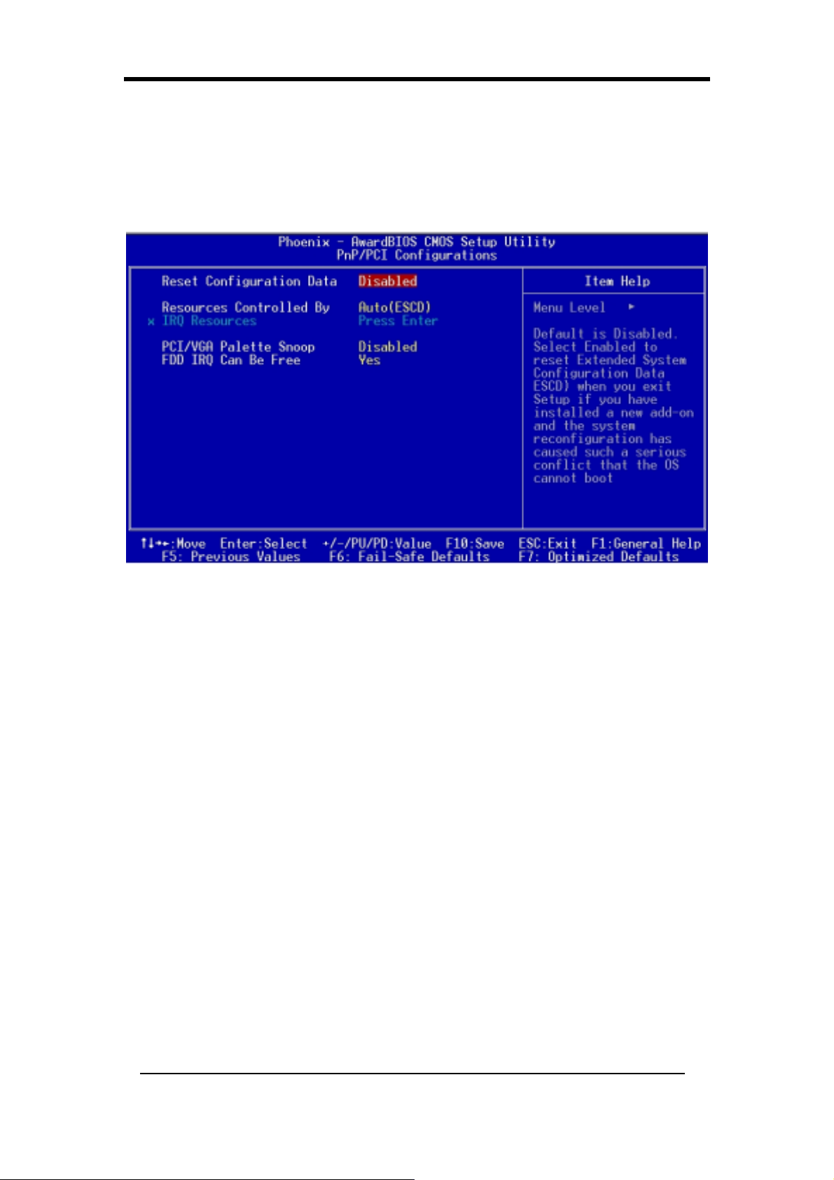
Chapter 3
3-6 PNP/PCI Configurations
This section provides IRQ and DMA setting information. By choosing the PNP/PCI
Configuration option from the CMOS Setup Utility menu (Figure 3-1), the screen that
lists the manufacturer's default values for the motherboard is displayed below.
Figure 3-7 PNP/PCI Configurations
Reset Configuration Data:
Default is [Disabled]. Select Enabled to reset Extended System Configuration Data
(ESCD) if you have installed a new add-on and the system reconfiguration has caused
such a serious conflict that the OS cannot boot.
Resources Controlled By:
When set to Manual the system BIOS will not refer to ESCD for IRQ & DMA
information. Instead, it will refer to the items in the setup menu for assigning IRQ &
DMA. When set to Auto the system BIOS will refer to ESCD for all legacy
information. ESCD (Extended System Configuration Data) provides a detailed
format of the configuration data structures stored in flash memory. Each data structure
defines the resources used by a device or a card in the system. This includes legacy
and PCI/ISA PnP devices.
PCI/VGA Palette Snoop:
When set to [Enabled], multiple VGA devices operating on different buses can
handle data from CPU to each set of palette registers of every video device. Bit 5 of
the command register in the PCI device configuration space is the VGA Palette Snoop
bit (0 is disabled). Available options are [Enabled] and [Disabled].
86
Page 95
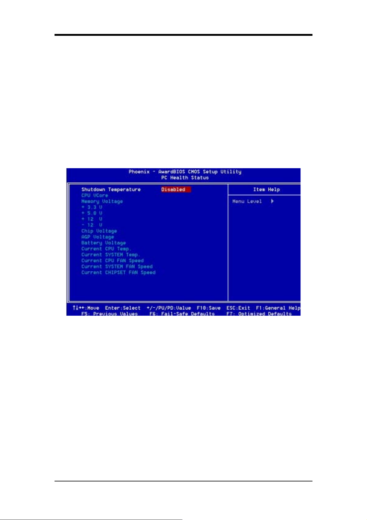
Chapter 3
FDD IRQ Can Be Free:
This function allows users to choose if the FDD IRQ can be freed up. The default
setting is [Ye s ].
3-7 PC Health Status
By choosing the PC Health Status option from the CMOS Setup Utility menu (Figure
3-1), the screen below is displayed. This field shows you the current system
temperature/external voltages input and the current CPU FAN and System FAN
operating speed.
Figure 3-8 PC Health Status
Shutdown Temperature:
This item allows you to set the shutdown temperature level for the processor. When
the processor reaches the temperature you set, the system will shutdown. This
function only works in ACPI-aware OS (such as Windows 98 / ME / 2000).
Available options are [70°C/158°F], [65°C/149°F] and [60°C/140°F]
87
Page 96
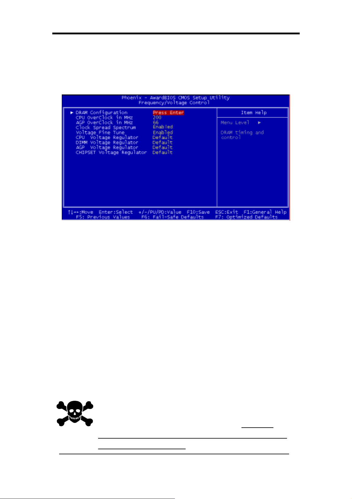
Chapter 3
3-8 Frequency/Voltage Control
By choosing the Frequency/Voltage Control option from the CMOS Setup Utility
menu (Figure 3-1), the screen that lists the manufacturer's default values for the
motherboard is displayed below.
Figure 3-9 Frequency/Voltage Control
DRAM Configuration:
1. DDR Timing Setting by
This function determines the memory speed. Available options: [Manual],
[Auto].
2. Max MemClock
This option is activated when DDR Timing Setting by is set to [Manual].When
DDR Timing Setting by is set to [Auto] this option is deactivated.
Available options: [100 MHz], [133 MHz], [166MHz], [200MHz].
CPU Overclock in MHz:
This function determines the CPU overclocking speed. Available options are from
[200 MHz] to [400MHZ].
AGP Overclock in MHz:
This function determines the AGP overclocking speed
Overclockability:
This motherboard is designed to support overclocking ability. However,
please make sure your peripherals are able to tolerate such abnormal
setting, while CPU clock speed is overclocked. Any attempt to operate
beyond product specifications is not recommended. We are not
responsible for damages caused by inadequate operation or settings
beyond product specifications.
88
Page 97
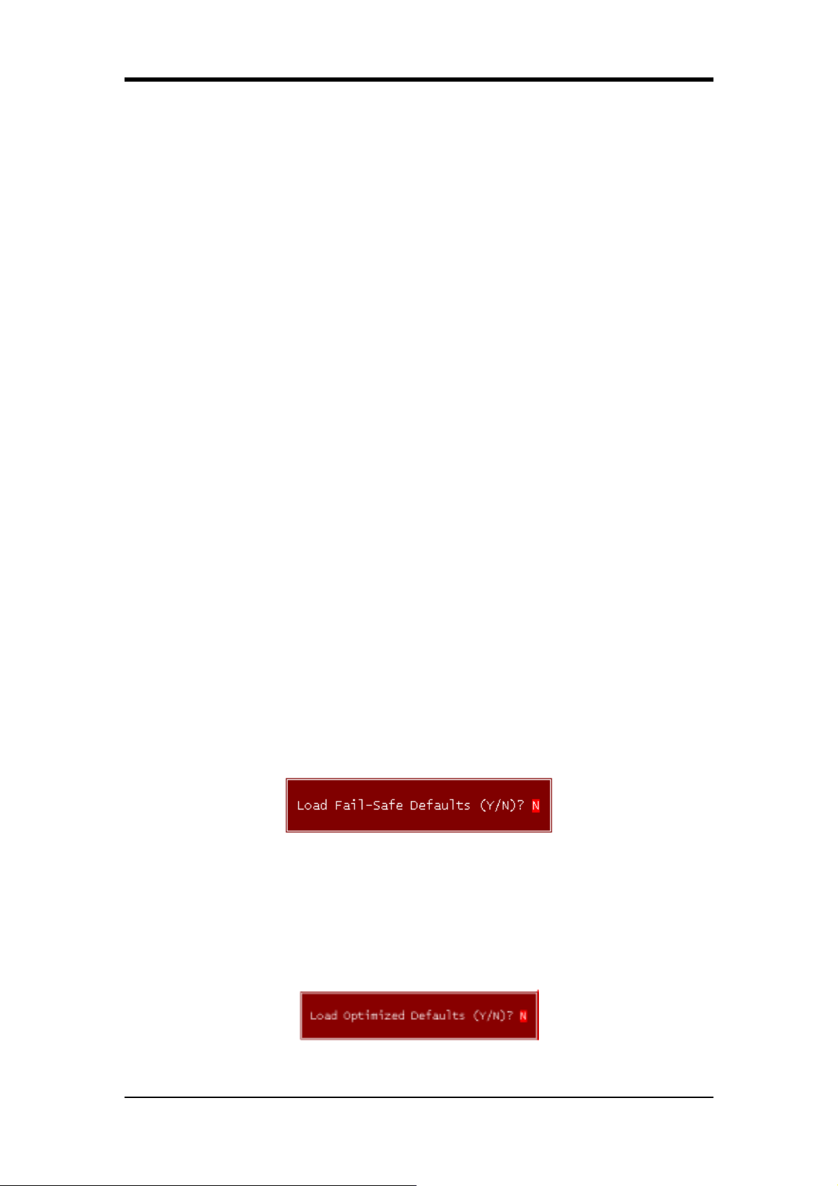
Chapter 3
Clock Spread Spectrum:
Avaliable Options: [Enabled], [Disabled].
Voltage Fine Tune:
When it is set to [Enabled], DIMM/AGP/CHIPSET/CPU Voltage Regulator options
are activated, and vice versa. Available options are [Enabled] and [Disabled].
CPU Voltage Regulator:
This feature determines the required voltage for the CPU. Available options are from
[1.450V] to [1.700V] & [Default].
DIMM Voltage Regulator:
This feature determines the required volatge for the system memory.
Available options are [2.7V] to [2.8V], [2.9V] & [Default].
AGP Voltage Regulator:
This feature determines the required volatge for the AGP bus. Available options are
[1.6V] to [2.2V] & [Default].
CHIPSET Voltage Regulator:
This feature determines the required voltage for the CHIPSET. Available options are
[1.7V], [1.8V], [1.9V] & [Default].
3-9 Load Fail-Safe Defaults
Load Fail-Safe Defaults loads the default BIOS values directly from the CMOS
Setup Utility menu (Figure3-1). If user-defined BIOS settings are corrupted and
therefore unusable, these defaults will be loaded automatically when you turn on the
computer.
3-10 Load Optimized Defaults
Load Optimized Defaults loads the default system values directly from the CMOS
Setup Utility menu (Figure3-1). If user-defined BIOS settings are corrupted and
therefore unusable, these defaults will be loaded automatically when you turn on the
computer.
89
Page 98
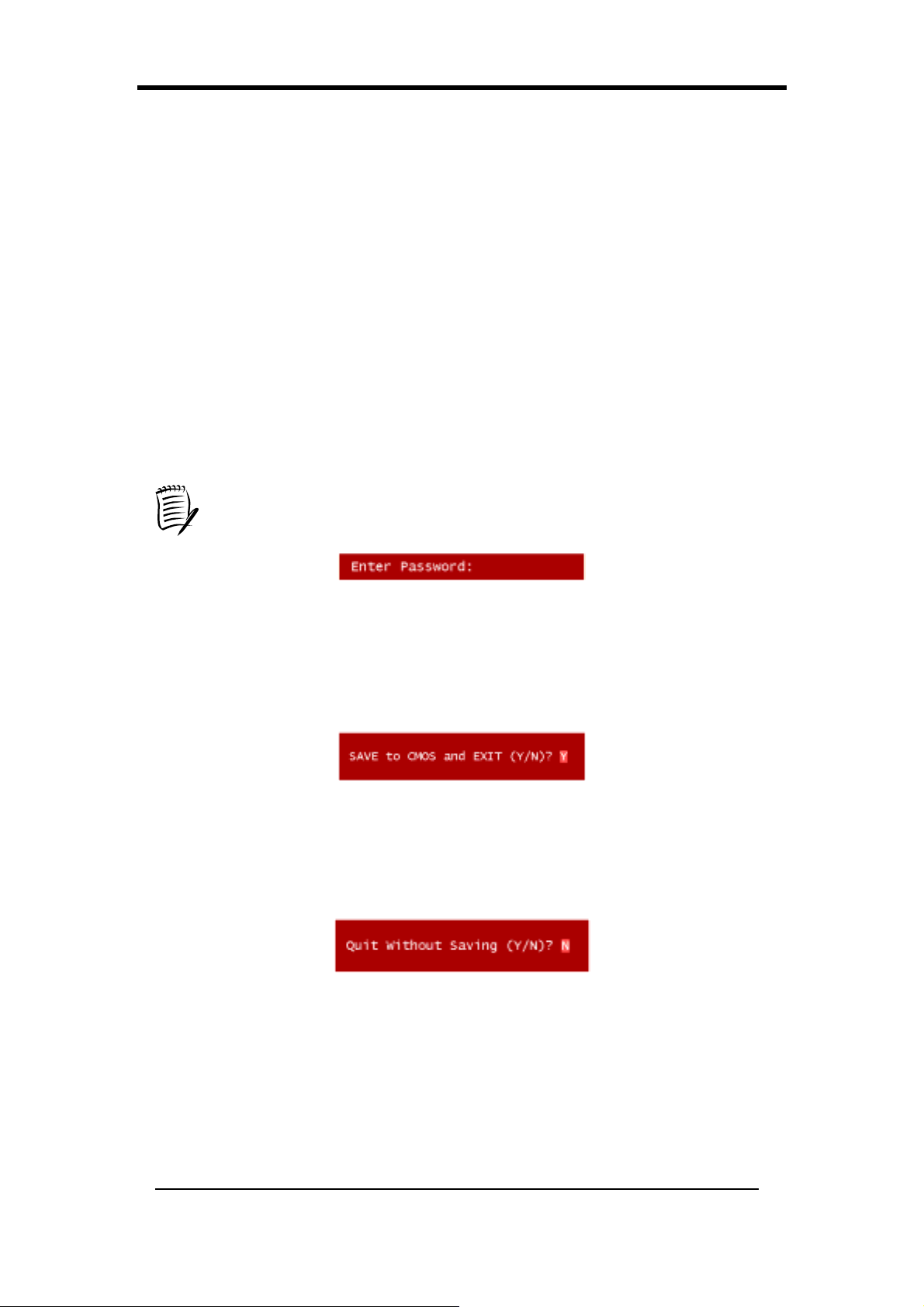
Chapter 3
3-11 Supervisor Password & User Password Setting
There are four different variables that control password settings. The first two are
located under the Security Option function in BIOS Features Setup Menu (Figure 3-1).
When the Security Option function is set to Setup, a password is required to enter
BIOS and change BIOS settings. When the Security Option function is set to
System, a password is required to enter both BIOS and computer's operating system
(For example, Windows 98) found on the boot drive.
The third and fourth variables are user password and supervisor password selected in
BIOS (Figure 3-1). The main purpose of separating users and supervisors is to allow
only the supervisor to have control over the BIOS settings. The user, on the other
hand, is only allowed to access computer's operating system and change the user
password in BIOS.
When there is no supervisor password being set, the user password controls
access to all BIOS settings.
3-12 Save and Exit Setup
If you select this and type [Y] followed by [Enter], the values entered in the setup
utilities will be recorded in the CMOS memory of the BIOS chip.
3-13 Exit Without Saving
Selecting this option and pressing [Y] followed by [Enter] lets you exit the Setup
program without recording any new values or changing old ones.
90
Page 99
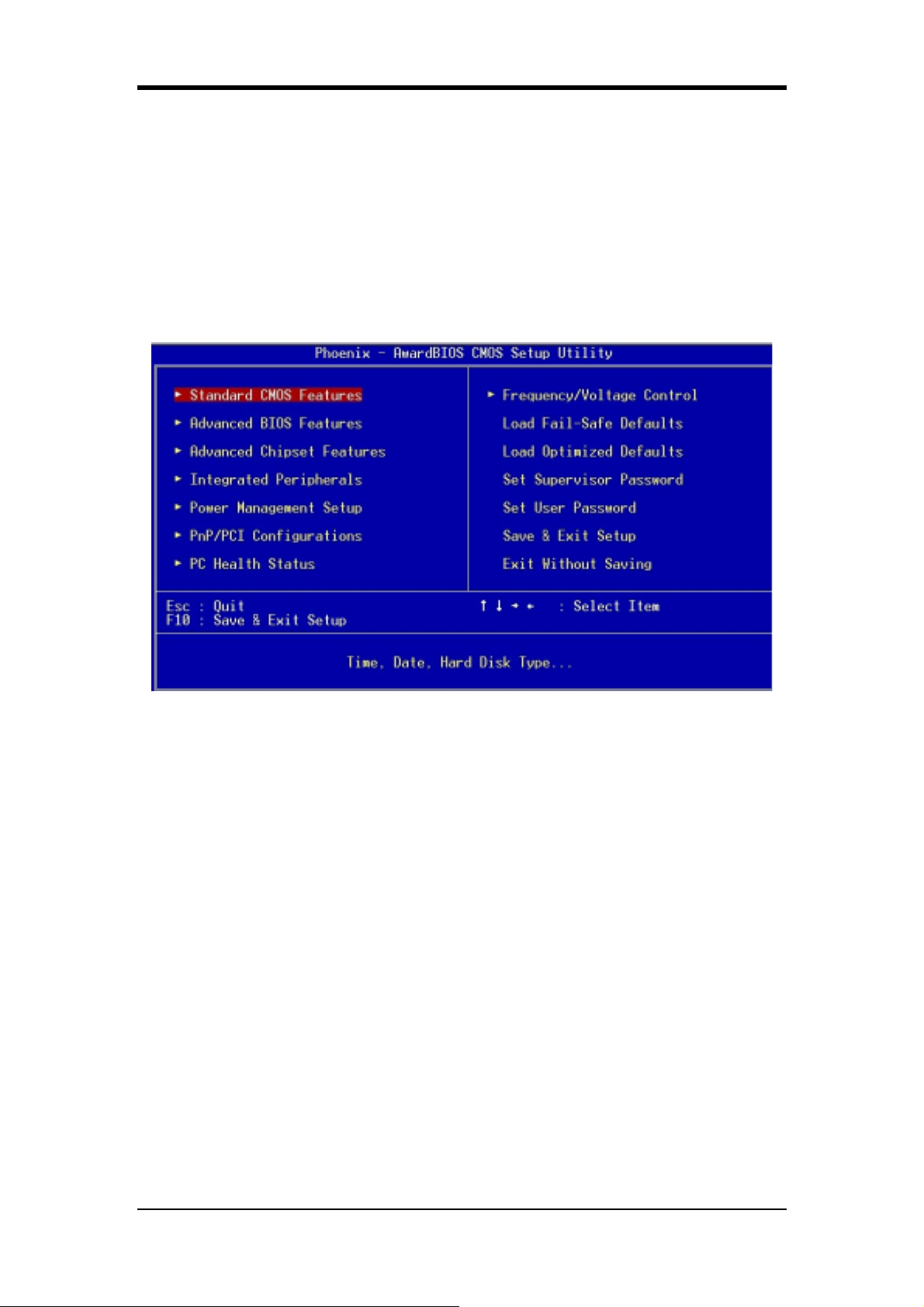
Chapter 3
BIOS 設定 (Chinese)
Phoenix-Award BIOS ROM 可讓使用者修改 BIOS 設定,並將所有設定的資料都
儲存在 CMOS ROM 裏面。
在您電腦開機時,請按 [Delete] 進入 Phoenix-Award BIOS 的設定項目。圖 3-10
是主畫面選單,以鍵盤選擇您要修改的項目並按下[Enter],就可進行更改。畫面
下方有畫面的操作指令。當您選擇較特殊的功能時,畫面右方會提供協助資訊供
您參考。
圖 3-10
91
Page 100
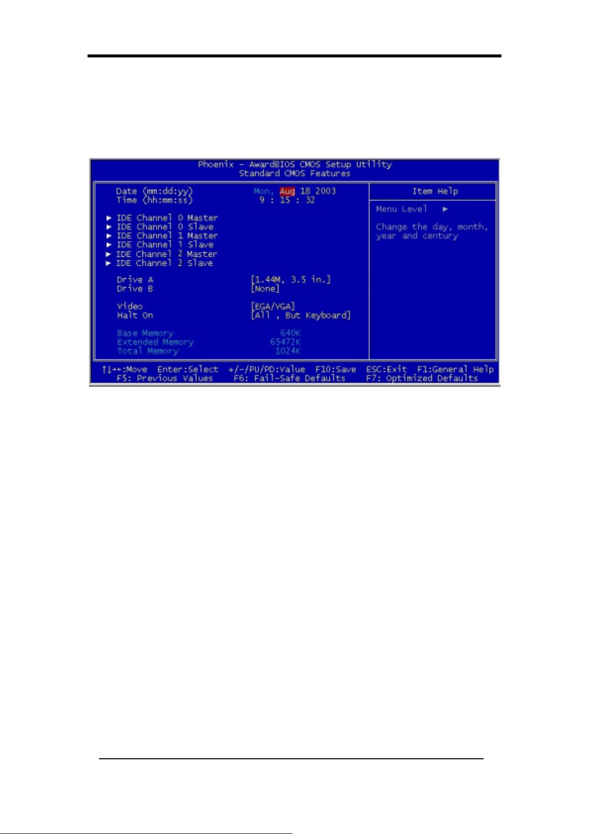
Chapter 3
3-14 基本 CMOS 設定
基本 CMOS 的設定,可讓使用者自行設定系統的各項硬體,如軟碟機、硬碟機、
顯示卡和日期、時間。當您第一次安裝主機板、更換硬體或當 CMOS 資料遺失時,
需要設定這些資料(如圖 3-11)。
圖 3-11
日期/時間
設定系統的日期和時間。
IDE 硬碟(Channel 0/1/2 之主要/次要裝置)
當硬碟正確地安裝硬碟於電腦系統時則可自動偵測出硬碟之容量大小。
設定軟碟機 A/B
此功能讓使用者可選擇不同的軟碟機的類型。可選擇的項目有[None],[360K,
5-1/4 in],[1.2M,5-1/4 in],[720k,3-1/2 in],[1.44M,3-1/2 in],和[2.88M,3-1/2
in]。
設定顯示卡
選擇您的系統影像。您可以不理會這項功能,只要您有安裝顯示卡,顯示卡之
BIOS 會自動幫您做最佳設定。
偵錯暫停設定
當您的系統開機時,BIOS 會執行系統的偵測。假如 BIOS 偵測到錯誤時,這個
功能將會暫停您的電腦運作。
92
 Loading...