


CHAINTECH
VNF4/Ultra
NVIDIA nForce4/Ultra
ATX Motherboard
User’s Guide

Declaration of Conformity
According to 47 CFR, Parts 2 and 15 of the FCC Rules
The following designated product:
EQUIPMENT: MAINBOARD
MODEL NO.: VNF4/Ultra
is a Class B digital device that complies with 47 CFR Parts 2 and 15 of the FCC
Rules. Operation is subject to the following two conditions:
1. This device may not cause harmful interference.
2. This device must accept any interference received, including interference that
may cause undesired operation.
This declaration is given to the manufacturer:
CHAINTECH AMERICA CORP.
4427 Enterprise St. Fremont, CA 94538, U.S.A.
http://www.chaintechusa.com
Chaintech President: Simon Ho
Signature:

Federal Communications Commission Statement
This device complies with FCC Rules Part 15. Operation is subject to the following two conditions:
* This device may not cause harmful interference.
* This device must accept any interference received, including interference that may cause undesired operation.
This equipment has been tested and found to comply with the limits for a Class B digital device, pursuant to
Part 15 of the FCC Rules. These limits are designed to provide reasonable protection against harmful interference
in a residential installation. This equipment generates, uses, and can radiate radio frequency energy. If this
equipment is not installed and used in accordance with the manufacturer's instructions, it may cause harmful
interference to radio communications. However, there is no guarantee that interference will not occur in a
particular installation. If this equipment does cause harmful interference to radio or television reception, which can
be determined by turning the equipment off and on, the user is encouraged to try to correct the interference by one
or more of the following measures:
* Reorient or relocate the receiving antenna.
* Increase the separation between the equipment and receiver.
* Connect the equipment to an outlet on a circuit different from that to which the receiver is connected.
* Consult the dealer or an experienced radio/TV technician for help.
The use of shielded cables for connection of the monitor to the graphics card is required to assure
compliance with FCC regulations. Changes or modifications to this unit not expressly approved by the party
responsible for compliance could void the user's authority to operate this equipment.
Canadian Department of Communications Statement
This digital apparatus does not exceed the Class B limits for audio noise emissions from digital apparatuses
set out in the Radio Interference Regulations of the Canadian Department of Communications.
Manufacturer's Disclaimer Statement
The information in this document is subject to change without notice and does not represent a commitment
on the part of the vendor. No warranty or representation, either expressed or implied, is made with respect to the
quality, accuracy or fitness for any particular purpose of this document. The manufacturer reserves the right to
make changes to the content of this document and/or the products associated with it at any time without obligation
to notify any person or organization of such changes. In no event will the manufacturer be liable for direct, indirect,
special, incidental or consequential damages arising out of the use or inability to use this product or documentation,
even if advised of the possibility of such damages. This document contains materials protected by copyright. All
rights are reserved. No part of this manual may be reproduced or transmitted in any form, by any means or for any
purpose without expressed written consent of it's authors. Product names appearing in this document are mentioned
for identification purposes only. All trademarks, product names or brand names appearing in this document are
registered property of their respective owners.
Printed in Taiwan.
Mar 2004
OST-CONSUMER
RECYCLED PAPER
100%

CHAPTER 1 INTRODUCTION......................................................................................................1
1-1 SPECIFICATIONS........................................................................................................................1
1-2 BENEFITS & FEATURES..............................................................................................................3
1-3 PACKAGE CONTENTS.................................................................................................................5
1-4 LAYOUT ...................................................................................................................................6
CHAPTER 2 HARDWARE..............................................................................................................7
2-1 PC D.I.Y. ASSEMBLY INSTRUCTIONS..........................................................................................7
2-2 JUMPERS ..................................................................................................................................9
2-3 CONNECTORS .........................................................................................................................10
CHAPTER 3 BIOS SETUP PROGRAM.......................................................................................18
3-1 STANDARD CMOS SETUP .......................................................................................................18
3-2 ADVANCED BIOS FEATURES ...................................................................................................19
3-3 ADVANCED CHIPSET FEATURES ...............................................................................................19
3-4 INTEGRATED PERIPHERALS......................................................................................................19
3-5 POWER MANAGEMENT SETUP .................................................................................................19
3-6 PNP/PCI CONFIGURATIONS.....................................................................................................19
3-7 PC HEALTH STATUS ................................................................................................................19
3-8 FREQUENCY/VOLTAGE CONTROL ............................................................................................19
3-9 LOAD FAIL-SAFE DEFAULTS....................................................................................................20
3-10 LOAD OPTIMIZED DEFAULTS.................................................................................................20
3-11 SUPERVISOR PASSWORD & USER PASSWORD SETTING ............................................................20
3-12 SAVE AND EXIT SETUP...........................................................................................................20
3-13 EXIT WITHOUT SAVING .........................................................................................................20
BIOS 設定 (CHINESE).................................................................................................................21
3-14 基本 CMOS 設定 ..............................................................................................................21
3-15 進階晶片組的設定.............................................................................................................21
3-16 內建周邊裝置設定.............................................................................................................22
3-17 電源管理設定................................................................................................................22
3-18 電腦狀態............................................................................................................................22
3-19 電壓頻率的控制 ............................................................................................................22
3-20 載入原始設定.....................................................................................................................22
3-21 載入快速設定................................................................................................................22
3-22 管理人密碼或使用者密碼設定..........................................................................................22
3-23 存檔或離開設定............................................................................................................23
3-24 離開不存檔.....................................................................................................................23
PROGRAMME SETUP DU BIOS (FRENCH).............................................................................24

3-25 STANDARD CMOS SETUP (SETUP DU CMOS STANDARD).......................................................24
3-26 ADVANCED BIOS FEATURES (FONCTIONNALITÉS AVANCÉES DU BIOS)...................................25
3-27 ADVANCED CHIPSET FEATURES (FONCTIONNALITÉS AVANCÉES DU CHIPSET)...........................25
3-28 INTEGRATED PERIPHERALS....................................................................................................25
3-29 POWER MANAGEMENT SETUP (PARAMÉTRAGE DE GESTION D’ALIMENTATION).......................25
3-30 PNP/PCI CONFIGURATIONS...................................................................................................25
3-31 PC HEALTH STATUS ..............................................................................................................26
3-32 FREQUENCY/VOLTAGE CONTROL...........................................................................................26
3-33 LOAD FAIL-SAFE DEFAULTS ..................................................................................................26
3-34 LOAD OPTIMIZED DEFAULTS (CHARGER LES VALEURS PAR DÉFAUTS OPTIMISÉES)..................26
3-35 SUPERVISOR PASSWORD & USER PASSWORD SETTING (PARAMÉTRAGE DE MOT DE PASSE
SUPERVISEUR & MOT DE PASSE UTILISATEUR)...............................................................................26
3-36 SAVE AND EXIT SETUP (ENREGISTRER ET QUITTER LE MENU SETUP).......................................27
3-37 EXIT WITHOUT SAVING (QUITTER SANS ENREGISTRER)..........................................................27
BIOS SETUP PROGRAM (GERMAN).........................................................................................28
3-38 STANDARD CMOS SETUP......................................................................................................28
3-39 ADVANCED BIOS FEATURES(ERWEITERTE BIOS FUNKTIONEN)..............................................29
3-40 ADVANCED CHIPSET FEATURES(ERWEITERTE CHIPSATZ FUNKTIONEN)....................................29
3-41 INTEGRATED PERIPHERALS(INTEGRIERTE PERIPHERIGERÄTEN)...............................................29
3-42 POWER MANAGEMENT SETUP(STROMFÜHRUNGSEINSTELLUNGEN).........................................29
3-43 PNP/PCI CONFIGURATIONS(PNP/PCI EINSTELLUNGEN)........................................................29
3-44 PC HEALTH STATUS(PC GESUNDHEITSZUSTAND)...................................................................30
3-45 FREQUENCY/VOLTAGE CONTROL(FREQUENZ/SPANNUNGS EINSTELLUNG)..............................30
3-46 LOAD FAIL-SAFE DEFAULTS(FEHL-SICHER STANDARTWERTE LADEN).....................................30
3-47 LOAD OPTIMIZED DEFAULTS(OPTIMIERTEN STANDARTWERTE LADEN)....................................30
3-48 SUPERVISOR PASSWORD & USER PASSWORD SETTING(SUPERVISOR- UND NUTZER -PAßWORT
EINSTELLUNGEN).........................................................................................................................30
3-49 SAVE AND EXIT SETUP(SPEICHERN UND SETUP VERLASSEN)...................................................31
3-50 EXIT WITHOUT SAVING(BEENDEN OHNE ZU SPEICHERN).........................................................31
ПРОГРАММА НАСТРОЙКИ BIOS (RUSSIAN)........................................................................32
3-51 РАЗДЕЛ STANDARD CMOS SETUP..........................................................................................32
3-52 ADVANCED BIOS FEATURES (РАСШИРЕННЫЕ ВОЗМОЖНОСТИ BIOS).....................................33
3-53 ADVANCED CHIPSET FEATURES (РАСШИРЕННЫЕ НАСТРОЙКИ НАБОРА МИКРОСХЕМ)...............33
3-54 INTEGRATED PERIPHERALS (ВСТРОЕННЫЕ ПЕРИФЕРИЙНЫЕ УСТРОЙСТВА).............................33
3-55 POWER MANAGEMENT SETUP (НАСТРОЙКА УПРАВЛЕНИЯ ПИТАНИЕМ)...................................33
3-56 PNP/PCI CONFIGURATIONS (КОНФИГУРАЦИИ PNP/PCI).......................................................33
3-57 PC HEALTH STATUS (СОСТОЯНИЕ ЗДОРОВЬЯ ПК)..................................................................34

3-58 FREQUENCY/VOLTAGE CONTROL (УПРАВЛЕНИЕ ЧАСТОТОЙ / НАПРЯЖЕНИЕМ)........................34
3-59 LOAD FAIL-SAFE DEFAULTS (ЗАГРУЗИТЬ БЕЗОПАСНЫЕ НАСТРОЙКИ ПО УМОЛЧАНИЮ)...........34
3-60 LOAD OPTIMIZED DEFAULTS (ЗАГРУЗИТЬ ОПТИМИЗИРОВАННЫЕ НАСТРОЙКИ ПО УМОЛЧАНИЮ)
....................................................................................................................................................34
3-61 SUPERVISOR PASSWORD & USER PASSWORD SETTING (УСТАНОВКА ПАРОЛЯ АДМИНИСТРАТОРА
И ПОЛЬЗОВАТЕЛЯ).........................................................................................................................34
3-62 SAVE AND EXIT SETUP (СОХРАНИТЬ И ВЫЙТИ).......................................................................35
3-63 EXIT WITHOUT SAVING (ВЫЙТИ БЕЗ СОХРАНЕНИЯ)................................................................35
BIOS 설정 프로그램 (KOREAN).................................................................................................36
3-64 기본 CMOS 설정 ..............................................................................................................36
3-65 BIOS 기능 설정 .................................................................................................................37
3-66 CHIPSET 기능설정...............................................................................................................37
3-67 주변기기 설정 ...................................................................................................................37
3-68 전원 관리 기능 설정.........................................................................................................37
3-69 PNP/PCI 구성 .....................................................................................................................37
3-70 PC HEALTH 상태 .................................................................................................................37
3-71 FREQUENCY/VOLTAGE 조정 .................................................................................................37
3-72 안정된 설정 불러오기 ......................................................................................................38
3-73 최적화된 설정 불러오기 ...................................................................................................38
3-74 관리자 PASSWORD 와 사용자 PASSWORD 설정..................................................................38
3-75 저장하고 나가기 설정.......................................................................................................38
3-76 저장하지 않고 나가기 설정..............................................................................................38
CHAPTER 4 SOFTWARE.............................................................................................................39
APPENDIX.....................................................................................................................................50
A-1 INSTALLING WINDOWS 2000/XP ON A SATA DRIVE .................................................................50
NOTE..............................................................................................................................................51
Revision History
Revision Description P/N
V.1_M Original Issue 9415257010
V.2_M Address update 9415257020

Chapter 1
1
Chapter 1 Introduction
1-1 Specifications
CPU
- Supports AMD Socket-939 Athlon 64 FX / Athlon 64
- Processor interface via 2000MT/s Hyper Transport bus
Chipset
- NVIDIA nForce4 (VNF4) / nForce4 Ultra (VNF4 Ultra)
Memory
- Four 184- pin DDR DIMMs up to 4GB
- Supports Dual Channel DDR266/333/400 memory
Expansion Slots
- One PCI Express x16 port for PCI Express graphics card
- Two PCI Express x1 ports
- Three 32-Bit PCI slots (v2.3 compliant)
7.1- Channel Audio
- Supports enhanced NVIDIA 7.1-channel audio
- Complies with AC’97 Rev 2.3 specifications
- Six audio jacks with automatic jack sensing
- Supports 48KHz coaxial S/PDIF output
- EAX/Direct Sound 3D/13DL2/A3D compatible
SATA
- Supports four native SATA 1.5Gb/s devices (VNF4)
- Supports four native SATA2 3.0Gb/s devices (VNF4 Ultra)
- Hot-swap capability, allowing disks to be changed without powering down
the system.
- Optimized for the high-performance NVIDIA RAID technology
- Supports SATA ATAPI devices
IDE
- Supports 2 UltraDMA-66/100/133 IDE ports
FDD
- One FDD connector supports up to 2.88MB
USB 2.0
- Supports total 10 USB 2.0 ports with High-Speed Device @ 480 Mb/s
Transfer Rates
NVIDIA Gigabit Ethernet
- Supports 10/100/1000Base-T Gigabit Ethernet with external PHY

Chapter 1
2
NVIDIA ActiveArmor (VNF4 Ultra)
- A dedicated secure networking engine enhances networking security while
reducing CPU overhead
- Specialized features defend against spyware intrusions and hacker attacks
- An intelligent application manager alerts you when unknown applications
attempt to access the network
- Supports the new Microsoft networking architecture for fast and secure
networking
Boot-Block Flash ROM
- Award system BIOS support PnP, APM, DMI, ACPI, & Multi-device booting
features
System Monitor
- Temperatures sensing for CPU and system
- Fan speed monitoring and control for CPU and system
Rear Panel I/O ports
- PS/2 Mouse and Keyboard port
- 25-pin D-Sub female Parallel port
- Two 9-pin D-Sub male Serial ports
- Four USB ports and one RJ45 connector
- 6-port Audio Jack for 7.1-Channel and S/PDIF output
Internal I/O connectors
- Four 3x1 pin fan connectors
- Three 5x2 pin USB connectors for additional 6USB ports
- 3x1 pin wake on LAN connector with housing
- 3x1 pin wake on Modem connector with housing
- Two 4x1 pin CD-in connectors with 2.54mm pitch housing
- 5x2 pin Front Audio connector
- 9x2 pin Front Panel connector
- 24 pin ATX Power connector
- 4 pin ATX 12V Power connector
Form Factor
- ATX Form Factor 305mm x 220mm

Chapter 1
3
1-2 Benefits & Features
NVIDIA nForce4/nForce4 Ultra chipset
l PCI Express Support
Designed to run perfectly with the next-generation PCI Express bus architecture.
This new bus doubles the bandwidth of the AGP 8X bus, delivering over 4 GB
per second in both upstream and downstream data transfers.
l NVIDIA nTune Performance Application
Enables the easiest, safest, and highest performing overclocking available for
NVIDIA nForce-based PCs. Performance wizards allow automatic tuning for
the best performance or the quietest operation. Previously known as the NVIDIA
System Utility.
l NVIDIA Firewall
A high-performance, hardware-optimized firewall, NVIDIA Firewall protects
your PC from intruders by filtering unauthorized traffic. Integrated into select
NVIDIA nForce MCPs (media communication processors) with NVIDIA Gigabit
Ethernet, it provides professional-grade traffic inspection capabilities, advanced
management features--remote access, configuration, and monitoring--and is easy
to use and setup via a user-friendly wizard.
l NVIDIA RAID
NVIDIA RAID technology implements standard RAID 0, RAID 1, and RAID
0+1 techniques to maximize storage assets. NVIDIA RAID technology
additionally introduces many innovations that simplify and optimize the
management of RAID features and disk resources.
l NVIDIA Native Gigabit Ethernet
The industry’s fastest Gigabit Ethernet performance, eliminates network
bottlenecks and improves overall system efficiency and performance.
l NVIDIA NVMixer Application
Completely control all aspects of the NVIDIA nForce audio
experience—including volume adjustment, recording options, and speaker
configuration—through easy-to-follow wizards.
l 64-Bit Architecture
NVIDIA nForce4 and NVIDIA nForce3 MCPs provide advanced processing
capabilities and system innovations for the 64-bit AMD processor architecture.
l Single-Chip Architecture
Revolutionary single-chip architecture enables higher-quality, full-featured
motherboards and delivers maximum performance with the lowest latency. The
single-chip design also means less power consumption and less heat dissipation.

Chapter 1
4
l Unified Driver Architecture (UDA)
Part of the NVIDIA Forceware unified software environment (USE). The
NVIDIA UDA guarantees forward and backward compatibility with software
drivers. Simplifies upgrading to a new NVIDIA product because all NVIDIA
products work with the same driver software.
l HyperTransport Technology
A state of the art I/O bus interface, delivering the highest continuous
throughput—800MB/s—between the nForce platform processors. Ensures data
and information are relayed through the system as quickly as possible.
l Serial ATA
Next-generation storage technology enables easy-to-install, high-performance,
low-power hard drives.
l NVIDIA nForce Networking
NVIDIA networking delivers the highest throughput for network transfers and
lower CPU utilization. The manageable and stable NVIDIA networking solution
results in better networking performance and a lower total cost of ownership.
l NVIDIA ForceWare Unified Software Environment (USE)
Ensures the best out-of-box experience for every user by delivering
industry-leading features for graphics, audio, video, communications, storage,
and security; one driver for all products; and continual performance and feature
updates over the life of the product.
l USB 2.0
A standard plug and play interface providing easy-to-use connectivity for USB
devices.
l NVIDIA ActiveArmor ( for NVIDIA nForce4 Ultra only)
Enhances network security while delivering the highest system performance by
offloading CPU-intensive packet filtering tasks in hardware, providing users with
a PC networking environment that is both fast and secure. Only supported in the
NVIDIA nForce4 SLI and Ultra MCPs.
l SATA 3Gb/s ( for NVIDIA nForce4 Ultra only)
Doubles bus bandwidth and provides blazingly high disk performance. Only
supported in the NVIDIA nForce4 SLI and Ultra MCPs.

Chapter 1
5
1-3 Package Contents
1. 1x IDE cable
2. 1x FDD cable
3. 2x SATA2 cable
4. 1x Power cable
5. 1x I/O shield
6. 1x Grease
7. 1x Manual
8. 1x Support driver CD
9. 1x Value Pack 2005
Note: If any of the foregoing objects is missing when you unpack the motherboard
package, please contact your retailer immediately.

Chapter 1
6
1-4 Layout

Chapter 2
7
Chapter 2 Hardware
2-1 PC D.I.Y. Assembly Instructions
1. Jumper Setting:
Set the CPU External Clock, Frequency Ratio and the CPU voltage according to the
instruction printed on the manual or silkscreen printed on the mainboard.
2. Installing FDD and IDE devices:
Aligned the red colored edge of the cable with the pin 1 of the drive connector on the
mainboard and gently attached it. Attach the other end of the cable by aligning the
colored edge to the pin 1 of the device connector. Make sure that all drives are
securely fastened.
3. Installing a CPU:
Locate a noticeable notch in the CPU’s corner. This marking indicate Pin 1 of the
CPU. Gently insert the CPU with Pin 1 at the same corner of the socket that contains
the end of the lever.
4. Installing System Memory:
Push module downward until side clips are properly secure to the module.

Chapter 2
8
Due to CPU specifications limitation, two DDR400 memory modules
inserted into DIMM1/3, three DDR400 into DIMM1/2/3, or four DDR400
into DIMM1/2/3/4 is not recommended.
5. Mounting a Mainboard into a Chassis:
Use standoffs and screws to securely mount the mainboard and make sure that all the
mounting holes are properly screwed.
6. Adding an expansion card:
Gently fasten the card to the proper slot.
7. Connecting I/O ports and device connectors:
Simply plug the cable into the respective device port or connector as shown in the
manual or silkscreen printed on the mainboard.
8. Connecting the Power Supply Cables:
Plug in the ATX power cable to the mainboard’s power connector and make sure the
cable is connected.
Note: It is strongly recommended using the ATX2.0 power supply with 24-pin and
4-pin plugs.
The use of certain power supplies such as AC BEL (API4PC01) is not
recommended.

Chapter 2
9
2-2 Jumpers
JP1 (CMOS Clear Jumper):
There is a CMOS RAM chip on board that has power
from external battery to retain the data and system
configuration. To clear the contents of the CMOS, please
follow the steps below.
1. Disconnect the system power supply from the
power source.
2. Set the jumper cap at location [2-3] for <5 seconds>, and then set it back to the
default position.
3. Connect the system's power and then start the system.
4. Enter BIOS's CMOS Setup Utility and choose Load Optimized Defaults. Type
[Y] and then press [Enter] to continue.
5. Set the system configuration in the Standard CMOS Setup menu.
JP5 (KB/MS Power On)
This motherboard can be turned on by the PS / 2 keyboard
(hot key). To use this function, select a hot key of your
choice at the Hot Key Power ON option under Wake Up
Events in the BIOS's Power Management Setup screen.
You must also set this jumper's cap to pins [2-3] to use
this function.
Pin
Definition
1-2 Normal (default)
2-3 Clear CMOS Data
Pin Definition
1-2 Disable
2-3 Enable

Chapter 2
10
JP6/6A (USB Power On)
A USB keyboard hot key or a USB mouse-click can
activate this motherboard. To use this function, select a
hot key of your choice at the USB Resume from S3
option under Wake Up Events in the BIOS's Power On
Management screen. You must also set this jumper's cap
to pins 2-3 to use this function.
2-3 Connectors
Rear Panel Connectors
1. PS/2 mouse port. The green 6-pin connector is used to connect your PS/2 mouse.
2. PS/2 keyboard port. The purple 6-pin connector is used to connect your PS/2
keyboard.
3. Parallel port. The 25-pin port is used to connect the parallel devices such as the
printer or scanner.
4. Serial ports. The 9-pin ports are used to connect the serial devices.
5. USB 2.0 ports. The 4-pin Universal Serial Bus (USB) ports are used to connect
the USB 2.0 devices.
6. RJ-45 port. The port can be used to connect the Local Area Network (LAN) via
the network devices.
7. Line-In port. The blue port is used to connect the audio devices such as the tape
player. The port also serves as the Digital Optical Output, which can connect the
optical fiber for the audio use.
Pin Definition
1-2 Disable
2-3 Enable
○
1
○
2
○
3
○
4
○
5
○
6
○
7
○
8
○
9
○
10
○
11
○
12

Chapter 2
11
8. Line-Out port. The green port is used to connect the audio devices such as the
headphone or speaker.
9. Microphone port. The pink port is used to connect the microphone.
10. Side Speaker-Out port. The black port is used to connect the side speakers in the
8-channel audio configuration
11. Rear Speaker-Out port. The gray port is used to connect the rear speakers in the
4-channel, 6- channel or 8-channel configuration.
12. Center/Subwoofer port. The yellow port is used to connect the center/subwoofer
speakers in the 6-channel or 8-channel audio configuration.
Internal Connectors
IDE 1/2 (IDE Hard-Disk Connector):
This motherboard has a 32-bit Enhanced PCI IDE and Ultra ATA66/100/133
controller that provides PIO mode 0~4, Bus Master, and Ultra ATA66/100/133
function. This connector is used for connecting ATAPI devices.
IDE 1 only connects two IDE devices. (Primary Master/Slave)
IDE 2 only connects two IDE devices. (Secondary Master/Slave)

Chapter 2
12
FD1 (Floppy Connector):
This motherboard provides a standard floppy disk drive connector that supports 360K,
720K, 1.2M, 1.44M and 2.88M floppy disk types. It is connected to a floppy disk
drive using 34 pins.
SATA 1/2/3/4 (Serial ATA Connector):
This motherboard comes with 4 Serial ATA connectors that can be connected to the
ATA 1.5GB/S (VNF4) or ATA2 3.0GB/S (VNF4 Ultra). In addition, they possess the
hot-swap capability that will allow you change SATA drives without powering down
the system. They also support Nvidia RAID0/1/0+1 for optimizing your system.
Chapter 2
13
FAN1/2/3/4 (CPU/System/ Case Fan /Chip Fan Connectors):
This motherboard's hardware management is able to detect the CPU and system fan
speed in rpm (revolutions per minute). The wiring and plugging may vary depending
on the manufacturer. On standard fans, the red is positive (+12V), the black is ground,
and the yellow wire is the rotation signal. Connect a 3rd part north-bridge cooling fan
to FAN4.
CN23A/23B/23C (USB Connector for USB 4/5,6/7 and 8/9):
If you want to use a USB Keyboard, you must enable the USB keyboard support
function in the BIOS's Integrated Peripherals menu. This motherboard contains a USB
Host controller and a root hub with two connectors.

Chapter 2
14
CN24 (Front Audio Connector):
This connector gives you the option of a front-panel audio-jack cable to be plugged
into a case supporting front panel audio.
Remove the two jumper caps at pins [5-6] and [9-10] then plug it into the (optional)
cable connector. Pins [5-6] and [9-10] are shorted (default) to enable back-panel
audio.
CN1A (Front Panel Connector):
1. PWR-SW (Over-ride Power Button Connector):
The power button on the ATX chassis can be used as a normal power switch as well
as a device to activate the Advanced Power Management Suspend mode. This is a
power-saving mode used for saving electricity when the computer is idle for long
periods of time. The Soft-OFF by PWR-BTTN function in BIOS's Power
Management Setup menu must be set to [Delay 4 Sec.] to activate this function.
When the Soft-OFF by PWR-BTTN function is enabled, pressing the power button
rapidly will switch the system to Suspend mode. Any occurrence of external
activities such as pressing any keys on the keyboard or moving the mouse will
bring the system back to Full-On. Pushing the button while in Full-On mode for
more than [4 seconds] will switch the system completely off. See Over-ride Power
Button Operation diagram.

Chapter 2
15
2. P-LED (Power LED Connector):
The power indicator LED shows the system's power status. It is important to pay
attention to the correct cable and pin orientation (i.e. Be careful not to reverse the
order of these two connectors.)
3. G-BTN (Green Button Switch):
Some ATX cases provide a Green button switch, which is used to put the system in
Suspend mode. While in Suspend mode, the power supply to the system is reduced
to a trickle, the CPU clock is stopped, and the CPU core is in its minimum power
state. The system is activated whenever the keyboard or mouse is touched. The
system will resume in various ways as defined by Power Management Setup screen
in BIOS.
4. RESET (System Reset Switch Connector):
This connector should be connected to the reset switch on the front panel of the
system case. The reset switch allows you to restart the system without turning the
power off.
5. SPEAKER (Speaker Connector):
This 4-pin connector connects to the case-mounted speakers.
6. HD-LED (IDE - Activity LED Connector):
The IDE- activity LED lights up whenever the system reads/writes to the IDE
devices.
CN2/2A (CD-IN):
These connectors are responsible for connecting the CD-ROM to receive sound
signals.
Chapter 2
16
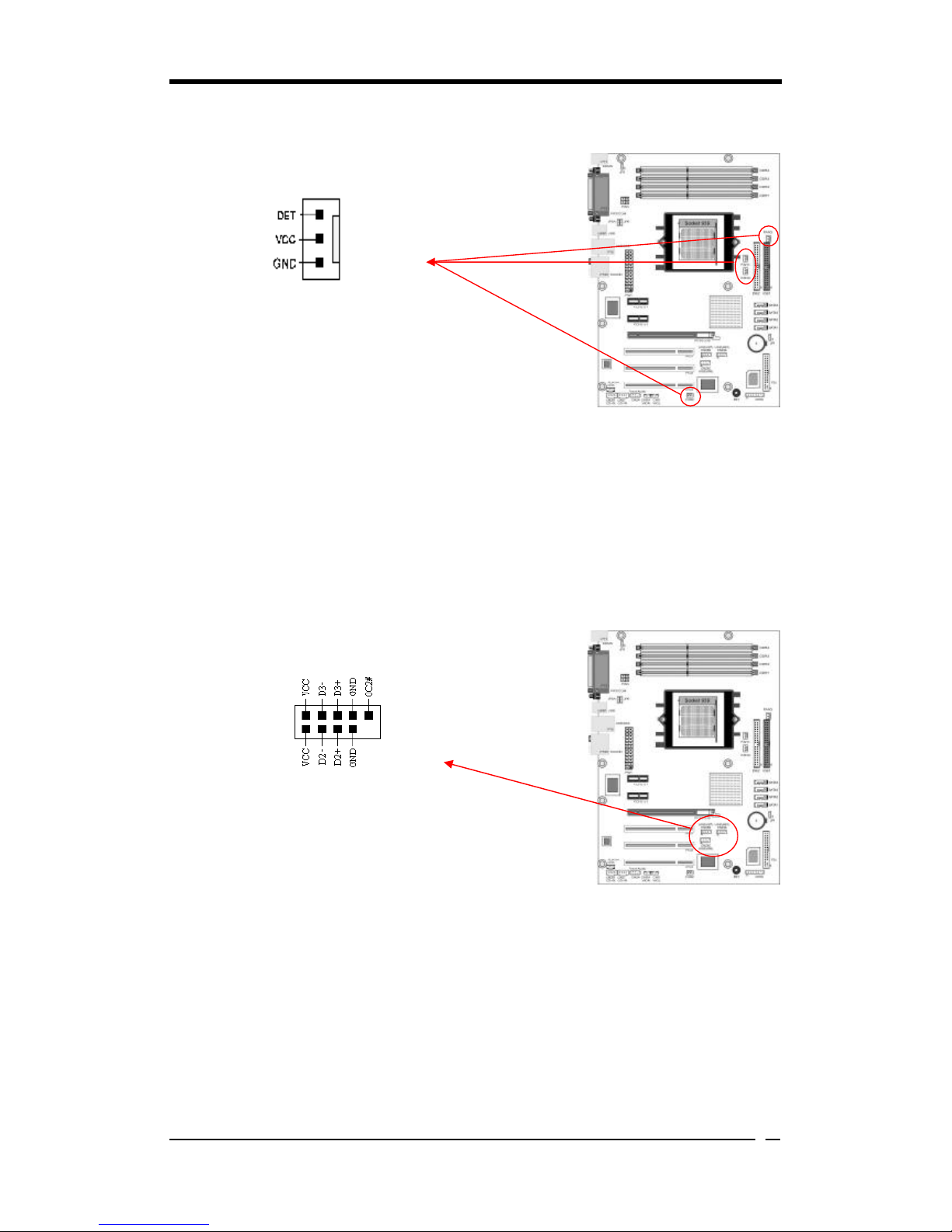
CN3 (AUX-IN):
The connector is responsible for connecting devices such
as the TV tuner, CD-ROM or MPEG card to receive
sound signals.
CN5 [WOL (Wake-on-LAN) Connector]:
Enable Wake On LAN in the BIOS's Power Management Menu to use this function.
The capability to remotely manage PCs over networks is a significant factor in
reducing administrative and ownership costs. Magic Packet technology is designed
with WOL ability to LAN controllers. This header is used to connect an add-in NIC
(Network Interface Card) that provides WOL function to the motherboard.

Chapter 2
17
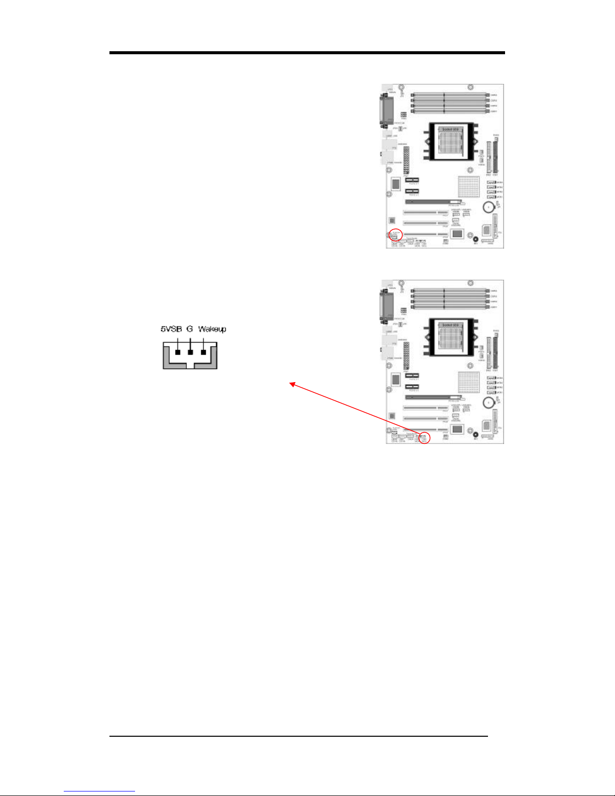
CN5A [WOM (Wake-on-Modem) Connector]:
Enable the Wake On Modem selection in the BIOS's Power Management Menu to
activate this function. This header is used to connect an add-in modem card, which
provides WOM function to the motherboard.
PCI-Express slots: PCI-E X16 & PCI-E1/ PCI-E2
PCI-E x16 slots are for installing PCI-Express graphics
cards. The PCI-E x1 slot is for expansion cards which fit
the PCI-E x1 slot.
Chapter 3
18
Chapter 3 BIOS Setup Program
Phoenix-Award BIOS ROM has a built-in setup program that allows users to modify
the basic system configuration. This information is stored in CMOS RAM so that it
can retain the setup information even when the power is turned off. Press [Delete]
when you Power on or Reboot the computer system. (i.e. After Intel Pentium 4 logo
appears at the center of the screen, please press [Delete] to enter the BIOS setup
program).
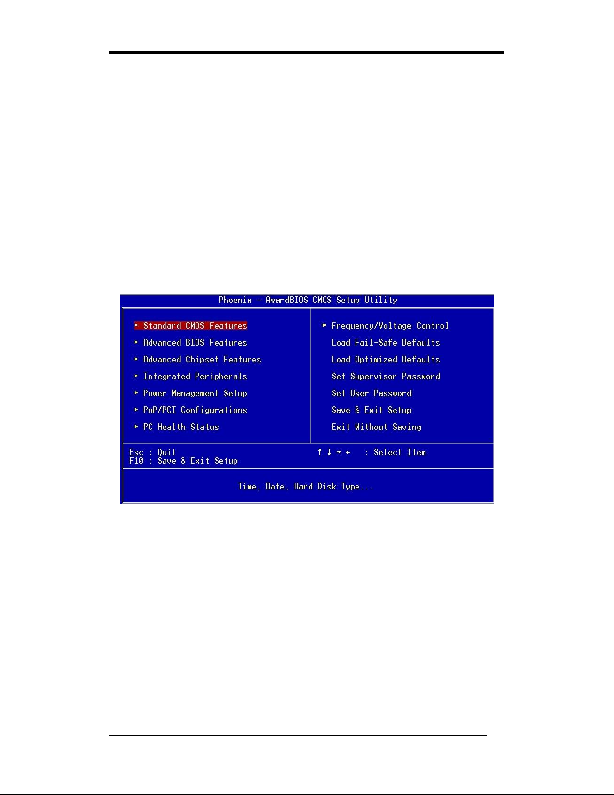
The primary screen as shown in Figure 3-1 is a list of the menus and functions
available in the setup program. Select the desired item by using arrow keys and press
[Enter] to make the changes. Operating commands are located at the bottom of this
and all other BIOS screens. When a field is highlighted, on-line help information is
displayed on the right side of the screen.
Figure 3-1 Setup Program Initial Screen
3-1 Standard CMOS Setup
The Standard CMOS Setup allows users to configure system components such as
hard-disk drive, floppy-disk drive and video display as well as date, time and boot up
error signaling. This configuration menu should be changed when installing a
motherboard for the first time, or changing hardware such as HDD, FDD, and video
display in your system, or when the CMOS data was lost or corrupted. Choose the
Standard CMOS Setup option from the CMOS Setup Utility menu (Figure 3-1) to
display the following screen:

Chapter 3
19
3-2 Advanced BIOS Features
The motherboard manufacturer determines all of these settings. The default values
should not be modified unless necessary.
3-3 Advanced Chipset Features
The motherboard manufacturer determines all of these settings. The default values
should not be modified unless necessary.
All of the above settings have been determined by the mother
board
manufacturer and should not be changed unless you are absolutely sure of
what you are do
ing. Explanations of the DRAM timing and chipset features
setup are lengthy, highly technical and beyond the scope of this manual. Below
are some brief descriptions of the functions in the Setup menu.
3-4 Integrated Peripherals
This section provides information on setting up the peripheral devices. The
motherboard manufacturer determines all of these settings. The default values should
not be modified unless necessary.
3-5 Power Management Setup
This section provides information on the Green PC power management functions. The
motherboard manufacturer determines all of these settings. The default values should
not be modified unless necessary.
3-6 PNP/PCI Configurations
This section provides IRQ and DMA setting information. The motherboard
manufacturer determines all of these settings. The default values should not be
modified unless necessary.
3-7 PC Health Status
The motherboard manufacturer determines all of these settings. The default values
should not be modified unless necessary. This field shows you the current system
temperature/external voltages input and the current CPU FAN and System FAN
operating speed.
3-8 Frequency/Voltage Control
The motherboard manufacturer determines all of these settings. The default values
should not be modified unless necessary.

Chapter 3
20
3-9 Load Fail-Safe Defaults
Load Fail-Safe Defaults loads the default BIOS values directly from the CMOS
Setup Utility menu (Figure3-1). If user-defined BIOS settings are corrupted and
therefore unusable, these defaults will be loaded automatically when you turn on the
computer.
3-10 Load Optimized Defaults
Load Optimized Defaults loads the default system values directly from the CMOS
Setup Utility menu (Figure3-1). If user-defined BIOS settings are corrupted and
therefore unusable, these defaults will be loaded automatically when you turn on the
computer.
3-11 Supervisor Password & User Password Setting
There are four different variables that control password settings. The first two are
located under the Security Option function in BIOS Features Setup Menu (Figure 3-1).
When the Security Option function is set to Setup, a password is required to enter
BIOS and change BIOS settings. When the Security Option function is set to
System, a password is required to enter both BIOS and computer's operating system
(For example, Windows 98) found on the boot drive. The third and fourth variables
are user password and supervisor password selected in BIOS (Figure 3-1). The main
purpose of separating users and supervisors is to allow only the supervisor to have
control over the BIOS settings. The user, on the other hand, is only allowed to access
computer's operating system and change the user password in BIOS.
When there is no supervisor password being set, the user password controls
access to all BIOS settings.
3-12 Save and Exit Setup
If you select this and type [Y] followed by [Enter], the values entered in the setup
utilities will be recorded in the CMOS memory of the BIOS chip.
3-13 Exit Without Saving
Selecting this option and pressing [Y] followed by [Enter] lets you exit the Setup
program without recording any new values or changing old ones.

Chapter 3
21
BIOS 設定 (Chinese)
Phoenix-Award BIOS ROM 可讓使用者修改 BIOS 設定,並將所有設定的資料都
儲存在 CMOS ROM 裏面。
在您電腦開機時,請按 [Delete] 進入 Phoenix-Award BIOS 的設定項目。圖 3-10
是主畫面選單,以鍵盤選擇您要修改的項目並按下[Enter],就可進行更改。畫面
下方有畫面的操作指令。當您選擇較特殊的功能時,畫面右方會提供協助資訊供
您參考。
圖 3-10
3-14 基本 CMOS 設定
基本 CMOS 的設定,可讓使用者自行設定系統的各項硬體,如軟碟機、硬碟機、
顯示卡和日期、時間。當您第一次安裝主機板、更換硬體或當 CMOS 資料遺失時,
需要設定這些資料。
3-15 進階晶片組的設定
從 CMOS 的設定清單中,選取[Advanced Chipset Features]。 這些選項功能由
製造商設定,除非必要,請維持在預設值。
全部的設定,須小心謹慎修改,並且確認修改無誤,否則請維持在預設值。有
關 DRAM 運作時間和晶片組的功能設定,是最煩瑣的,因此請照此使用手冊
做,以下是一些設定功能的簡單介紹。

Chapter 3
22
3-16 內建周邊裝置設定
這個章節提供周邊裝置設定的資訊。(在 CMOS 的主選單中,選取[Integrated
Peripherals]) 這些功能由製造商設定,除非必要,請維持在預設值。
3-17 電源管理設定
這個章節提供了電源管理的功能設定。在 CMOS 的主選單中,選取[Power
Management Setup]。這些功能由製造商設定,除非必要。請維持在預設值。
3-18 電腦狀態
CMOS 的主選單中,選取[PC Health Status]。提供目前系統溫度和電壓、CPU
的風扇轉速和系統風扇轉速的資訊。
3-19 電壓頻率的控制
CMOS 的主選單中,選取 [ Frequency/Voltage Control]。這些功能由製造商設定,
除非必要,請維持在預設值。
3-20 載入原始設定
CMOS 的主選單中,選取[Load Fail-Safe Defaults]。 若您的設定,造成錯誤,
或是無法開機的狀況時,您可選擇此功能,回復到最初的設定,電腦就可重新開
機。
3-21 載入快速設定
CMOS 的設定主清單中,選取[Load Optimized Defaults]。若您的設定,造成錯
誤,或是無法開機的狀況時,您可選擇此功能,回復到最佳的設定,以讓電腦可
重新開機。
3-22 管理人密碼或使用者密碼設定
控制此密碼有 4 種不同的設定。 第一 、 第二種的安全設定,可在 BIOS 的設
定清單中,直接選取。 這可自行設定安全密碼,但設定後,須再確認一次。 當
您設定安全密碼後,若要進入 BIOS,或是電腦的作業系統 (例如:Windows 98),
就必須輸入正確的密碼,才能進入 BIOS 或是電腦的作業系統。

Chapter 3
23
第三 、 第四種是系統管理者密碼和使用者密碼的安全設定,可在 BIOS 的設定
清單中,直接選取。此主要目地是爲了分隔使用者和系統管理者的許可權,只允
許系統管理者能進入所有的修改設定。而使用者只允許修改電腦的作業系統,和
修改自己設定的 BIOS 功能選項 。
若沒有設定系統管理人的密碼,則使用者密碼,就可設定全部的功能選項。
3-23 存檔或離開設定
若您在此選項中,選擇[Y] (即 Yes),然後再按 [Enter] 鍵,則會將您新的設定,
存入到 BIOS 中。
3-24 離開不存檔
若您在此選項中,選擇[Y] (即 Yes),然後再按 [Enter] 鍵,則會將您新的設定,
存入到 BIOS 中。

Chapter 3
24
Programme Setup du BIOS (French)
La ROM du BIOS Award Phoenix possède un programme d’installation intégré
permettant aux utilisateurs de modifier la configuration de base du système. Cette
information est stockée dans la RAM CMOS de sorte qu’elle peut conserver les
informations de paramétrage, même quand l’alimentation est coupée.
Pour entrer dans le programme d’installation du BIOS Award Phoenix appuyez sur
[Suppr] quand vous Allumez ou redémarrez le système de l’ordinateur. L’écran
principal, comme montré dans la Figure 3-19 est une liste des menus et des fonctions
disponibles dans le programme d’installation. Sélectionnez l’élément désiré à l’aide des
touches fléchées et appuyez sur entrée pour réaliser les modifications. Les commandes
d’exploitation sont situées au bas de celle-ci et sont présentes dans tous les écrans du
BIOS. Quand un champ est affiché en surbrillance, une information d’aide en ligne est
affichée sur la droite de l’écran.
Figure 3-19 Ecran de Départ du Programme Setup
3-25 Standard CMOS Setup (Setup du CMOS Standard)
Le “Standard CMOS Setup” permet aux utilisateurs de configurer les composants du
système tels que le disque dur, le lecteur de disquette et l’affichage vidéo ainsi que la
date, l’heure et la signalisation d’erreur de démarrage. Ce menu de configuration doit
être modifié lors de la première installation d’une carte mère, lors du changement de
matériels dans votre système tels que Disque Dur, Lecteur de Disquette, affichage vidéo,
ou quand les données CMPS ont été perdues ou corrompues. Choisissez l’option
“Standard CMOS Setup” dans le menu “CMOS Setup Utility” (Figure 3-19) pour
afficher l’écran suivant :

Chapter 3
25
3-26 Advanced BIOS Features (Fonctionnalités Avancées du BIOS)
En choisissant l’option “Advanced BIOS Features” dans le menu “CMOS Setup
Utility”, l’écran suivant s’affichera. Cet écran exemple contient les valeurs par défaut
du fabricant pour la carte mère.
3-27 Advanced Chipset Features (Fonctionnalités Avancées du
Chipset)
En choisissant l’option [Advanced Chipset Features] dans le menu “CMOS Setup
Utility”, l’écran suivant s’affichera. Cet écran exemple contient les valeurs par défaut
du fabricant pour la carte mère.
Tous les paramètres ci-
dessus ont été déterminés par le fabricant de la carte
mère et ne doivent pas être modifiés à moins d’êt
re absolument sûr de ce que
vous faites. Les explications sur le paramétrage de synchronisation DRAM et
des fonctionnalités du chipset sont longues, hautement techniques et dépassent
la porté de ce manuel. Vous trouverez ci-dessous quelques descriptions br
èves
des fonctions de ce menu de Paramétrage.
3-28 Integrated Peripherals
Cette section fournit des informations sur le paramétrage des périphériques. En
choisissant l’option “Integrated Peripherals” dans le menu “CMOS Setup Utility”,
l’écran suivant s’affichera. Cet écran exemple contient les valeurs par défaut du
fabricant pour la carte mère.
3-29 Power Management Setup (Paramétrage de Gestion
d’Alimentation)
Cette fonction fournit des informations sur les fonctions de gestion d’alimentation PC
Verte. En choisissant l’option “Power Management Setup” dans le menu “CMOS Setup
Utility”, l’écran suivant s’affichera. Cet écran exemple contient les valeurs par défaut
du fabricant pour la carte mère.
3-30 PNP/PCI Configurations
Cette section fournit des informations sur les paramètres IRQ et DMA. En choisissant
l’option “PNP/PCI Configuration” dans le menu “CMOS Setup Utility”, l’écran
suivant s’affichera. Cet écran contient les valeurs par défaut du fabricant de la carte
mère.

Chapter 3
26
3-31 PC Health Status
En choisissant l’option “PC Health Status” dans le menu “CMOS Setup Utility”,
l’écran suivant s’affichera. Ce champ vous montre l’entrée de température/ voltages
externes du système actuel et le VENTILATEUR DU CPU actuel et la vitesse de
fonctionnement du VENTILATEUR du système.
3-32 Frequency/Voltage Control
En choisissant l’option “Frequency/Voltage Control” dans le menu “CMOS Setup
Utility”, l’écran suivant s’affichera. Cet écran exemple contient les valeurs par défaut
du fabricant pour la carte mère.
3-33 Load Fail-Safe Defaults
"Load Fail-Safe Defaults" charge les valeurs du BIOS par défaut directement depuis
le menu "CMOS Setup Utility". Si l’enregistrement stocké créé par le programme
setup est endommagé et de ce fait inutilisable, ces valeurs par défaut seront chargées
automatiquement quand vous allumez l’ordinateur.
3-34 Load Optimized Defaults (Charger les Valeurs par Défauts
Optimisées)
"Load Optimized Defaults" charge les valeurs du système par défaut directement
depuis le menu "CMOS Setup Utility". Si l’enregistrement stocké créé par le
programme setup est endommagé et de ce fait inutilisable, ces valeurs par défaut seront
chargées automatiquement quand vous allumez l’ordinateur.
3-35 Supervisor Password & User Password Setting (Paramétrage de
Mot de Passe Superviseur & Mot de Passe Utilisateur)
Il existe quatre variables différentes contrôlant les paramètres de mot de passe. Les
deux premiers sont situés dans la fonction "Security Option" dans le Menu "BIOS
Features Setup". Quand la fonction "Security Option" est paramétrée sur "Setup", un
mot de passe est requis pour entrer dans le BIOS et modifier les paramètres du BIOS.
Quand la fonction "Security Option" est paramétrée sur "System", un mot de passe est
requis pour entrer dans le BIOS ainsi que dans le système d’exploitation de
l’ordinateur (par exemple Windows 98) trouvé dans le lecteur d’amorçage.
Les troisième et quatrième variables sont le mot de passe utilisateur et le mot de passe
superviseur sélectionnés dans le BIOS. Le but principal de séparer l’utilisateur et le
superviseur est de permettre uniquement au superviseur d’avoir le contrôle sur les

Chapter 3
27
paramètres du BIOS. L’utilisateur, d’un autre côté, est uniquement autorisé à
accéder au système d’exploitation de l’ordinateur et de modifier le mot de passe de
l’utilisateur dans le BIOS.
Remarque: quand il n’y a aucun mot de passe superviseur paramétré, le mot de passe
utilisateur contrôle l’accès à tous les paramètres du BIOS.
3-36 Save and Exit Setup (Enregistrer et Quitter le menu Setup)
Si vous sélectionnez cela tapez [Y] (pour Oui) suivi de la touche [Entrée], les valeurs
entrées dans les utilitaires de paramétrage seront enregistrées dans la mémoire CMOS
de la puce du BIOS.
3-37 Exit Without Saving (Quitter sans Enregistrer)
Le fait de sélectionner cette option et d’appuyer sur Y suivi de la touche [Entrée] vous
permet de quitter le programme Setup sans enregistrer de nouvelles valeurs ou d’en
modifier d’anciennes.

Chapter 3
28
BIOS Setup Program (German)
Phoenix-Award BIOS ROM verfügt über ein integriertes Setup-Programm, mit dem
Benutzer die grundlegende Systemkonfiguration ändern können. Diese Informationen
werden im CMOS RAM abgelegt, so dass die Setup-Informationen auch nach dem
Abschalten erhalten bleiben.
Um das Phoenix-Award BIOS Setup-Programm aufzurufen, drücken Sie [Delete]
nach dem Einschalten oder nach dem Neustart des Computersystems. Der
Hauptbildschirm in Abbildung 3-28 ist eine Liste der vorhandenen Menüs und
Funktionen des Setup-Programms. Wählen Sie mit den Pfeiltasten den gewünschten
Eintrag aus und drücken Sie Enter, um die Einstellung zu ändern. Bedienungsbefehle
werden in diesem und in anderen BIOS-Bildschirmen im unteren Bereich angegeben.
Wenn einer der Einträge markiert ist, werden auf der rechten Seite des Bildschirms
Online-Hilfsinformationen angezeigt.
Abbildung 3-28 Hauptfenster des Setup-Programms
3-38 Standard CMOS Setup
Diese Option ermöglicht es dem Benutzer, Systemkomponenten wie z.B.
Festplattenlaufwerk, Diskettenlaufwerk und Video-Display, sowie Datum, Uhrzeit und
Startfehlermeldungen zu konfigurieren. Dieses Konfigurationsmenü wird
normalerweise bei der Installation eines neuen Motherboards oder bei der Ersetzung
von Hardware-Komponenten im System, wie z.B. HDD, FDD, Video-Display, oder
wenn die CMOS-Daten beschädigt oder verloren wurden, geändert. Wenn Sie die
Standard CMOS-Setupoption aus dem CMOS Setup Utility-Menü (Abbildung 3-28)
wählen, wird der nachstehend gezeigte Bildschirm angezeigt.

Chapter 3
29
3-39 Advanced BIOS Features(Erweiterte BIOS Funktionen)
Wenn Sie die Advanced BIOS Features-Option aus dem CMOS Setup Utility-Menü
wählen, wird der nachstehend gezeigte Bildschirm angezeigt. Dieser
Beispielbildschirm zeigt die Standardangaben des Herstellers zum Mainboard.
3-40 Advanced Chipset Features(Erweiterte Chipsatz Funktionen)
Wenn Sie die [Advanced Chipset Features]-Option aus dem CMOS Setup
Utility-Menü wählen, wird der nachstehend gezeigte Bildschirm angezeigt. Dieser
Beispielbildschirm zeigt die Standardangaben des Herstellers zum Mainboard.
Alle hier angegebenen Einstellungen wurden vom Motherboard-
Hersteller
festgelegt und sollten niemals geändert werden, außer Sie kennen sich sehr gut
damit aus.
Die Erläuterung von DRAM Timing und Chipset Features ist sehr
lang, sehr technisch und ist nicht im umfang dieses Handbuchs enthalten.
Nachfolgend werden einige kurze Beschreibungen der Funktionen im
Setup-Menü aufgeführt.
3-41 Integrated Peripherals(Integrierte Peripherigeräten)
Dieser Abschnitt bietet Informationen zu der Einstellung von Peripheriegeräten. Wenn
Sie die Integrated Peripherals-Option aus dem CMOS Setup Utility-Menü wählen,
wird der nachstehend gezeigte Bildschirm angezeigt. Dieser Beispielbildschirm zeigt
die Standardangaben des Herstellers zum Mainboard.
3-42 Power Management Setup(Stromführungseinstellungen)
Dieser Abschnitt liefert Informationen über die Green PC-Power
Management-Funktionen. Wenn Sie die Power Management-Setupoption aus dem
CMOS Setup Utility-Menü wählen, wird der nachstehend gezeigte Bildschirm
angezeigt. Dieser Beispielbildschirm zeigt die Standardangaben des Herstellers zum
Mainboard.
3-43 PNP/PCI Configurations(PNP/PCI Einstellungen)
Dieser Abschnitt bietet IRQ- und DMA-Einstellungsinformationen. Wenn Sie die
PNP/PCI Configuration-Option aus dem CMOS Setup Utility-Menü wählen, wird der
nachstehend gezeigte Bildschirm angezeigt. Dieser Bildschirm zeigt die
Standardangaben des Herstellers zum Mainboard.

Chapter 3
30
3-44 PC Health Status(PC Gesundheitszustand)
Wenn Sie die PC Health Status-Option aus dem CMOS Setup Utility-Menü wählen,
wird der nachstehend gezeigte Bildschirm angezeigt. Dieser Bildschirm zeigt Ihnen die
aktuellen Systemtemperaturen / externen Spannungen und die aktuellen
Geschwindigkeiten von CPU FAN und System FAN.
3-45 Frequency/Voltage Control(Frequenz/Spannungs Einstellung)
Wenn Sie die Frequency/Voltage Control-Option aus dem CMOS Setup Utility-Menü
wählen, wird der nachstehend gezeigte Bildschirm angezeigt. Dieser
Beispielbildschirm zeigt die Standardangaben des Herstellers zum Mainboard.
3-46 Load Fail-Safe Defaults(Fehl-Sicher Standartwerte laden)
Mit der Funktion Load Fail-Safe Defaults werden die Standardwerte für das BIOS
direkt aus dem Utility-Menü des CMOS-Setup geladen. Wenn der vom
Setup-Programm erstellte Datensatz beschädigt und damit unbenutzbar wird, werden
diese Standardwerte automatisch beim Einschalten des Computers geladen.
3-47 Load Optimized Defaults(Optimierten Standartwerte laden)
Mit der Funktion Load Optimized Defaults werden die Standardwerte für das System
direkt aus dem Utility-Menü des CMOS-Setup geladen. Wenn der vom
Setup-Programm erstellte Datensatz beschädigt und damit unbenutzbar wird, werden
diese Standardwerte automatisch beim Einschalten des Computers geladen.
3-48 Supervisor Password & User Password Setting(Supervisor- und
Nutzer -Paßwort Einstellungen)
Es gibt vier verschiedene Variablen, die die Paßwort-Einstellungen steuern. Die
ersten zwei befinden sich bei der Funktion Security Option im BIOS-Menü Features
Setup. Wenn die Funktion Security Option auf Setup eingestellt ist, ist das Paßwort
für den Zugriff auf das BIOS und zum Ändern der BIOS-Einstellungen notwendig.
Wenn die Funktion Security Option auf System eingestellt ist, ist ein Paßwort sowohl
für den Zugriff auf das BIOS als auch auf das Betriebssystem des Computers (z.B.
Windows 98) notwendig, das sich im Bootlaufwerk befindet.
Die dritte und vierte Möglichkeit sind Paßwörter für Nutzer und Supervisor, die im
BIOS eingestellt werden . Nur der Supervisor soll die Möglichkeit haben, die

Chapter 3
31
Einstellungen im BIOS zu ändern. Der Nutzer hat nur Zugriff auf das
Betriebssystem des Computers, und er kann das Nutzer-Paßwort im BIOS ändern.
Hinweis: Wenn kein Supervisor-Paßwort eingerichtet wurde, ermöglicht auch das
Nutzer-Paßwort den Zugriff auf alle BIOS-Einstellungen.
3-49 Save and Exit Setup(Speichern und Setup verlassen)
Wenn Sie diese Option wählen, [Y] (Ja) eingeben und mit [Enter] bestätigen, werden
die in den Setup-Utilitys eingegebenen Werte im CMOS-Speicher des BIOS-Chips
gespeichert.
3-50 Exit Without Saving(Beenden ohne zu speichern)
Wenn Sie diese Option wählen, Y eingeben und mit [Enter] bestätigen, wird das
Setup-Programm beendet, ohne die neuen Einstellungen zu speichern oder die alten
Einstellungen zu löschen.

Chapter 3
32
Программа настройки BIOS (Russian)
Phoenix-Award BIOS ROM имеет встроенную программу настройки, которая
позволяет пользователям вносить изменения в базовую конфигурацию системы.
Эта информация записывается в CMOS RAM таким образом, что данные
настройки сохраняются даже при отключении питания.
Для входа в программу настройки Phoenix-Award BIOS нажмите на клавишу
[Delete], включаете питание (Power on) или перезагружаете (reboot) компьютер.
Первичный экран, как показано на Рис. 3-37, - это перечень меню и функций,
доступных в программе настройки. Посредством клавишей со стрелками
выберите нужный пункт и нажмите клавишу ввода для выполнения изменений.
Действующие команды расположены в нижней части этого и всех других
экранов BIOS. Когда поле выделено, оперативная справочная информация
выводится в правой части экрана.
Рис. 3-37 Первичный экран программы настройки
3-51 Раздел Standard CMOS Setup
Стандартная настройка CMOS (Standard CMOS) позволяет пользователям
конфигурировать такие компоненты системы, как привод жесткого диска,
флоппи-дисковод и дисплей, а также дату, время и сообщения об ошибках в
процессе загрузки. В это меню конфигурации следует вносить изменения при
установке впервые системной платы или при замене аппаратных устройств:
жесткий диск, флоппи-дисковод, дисплей, либо когда данные в CMOS
испорчены или потеряны. Выберите раздел «Standard CMOS Setup» из меню
«CMOS Setup Utility» (Утилиты настройки CMOS) (Рис. 3-37), чтобы вывести
следующий экран:

Chapter 3
33
3-52 Advanced BIOS Features (Расширенные возможности BIOS)
При выборе раздела «Advanced BIOS Features» из меню «CMOS Setup Utility»
(Утилиты настройки CMOS), появляется нижеприведенный экран. Этот пример
экрана содержит настройки производителя по умолчанию для системной платы.
3-53 Advanced Chipset Features (Расширенные настройки набора
микросхем)
При выборе раздела [Advanced Chipset Features] из меню Утилиты настройки
CMOS (CMOS Setup Utility) появляется следующий экран. Этот пример экрана
содержит настройки производителя по умолчанию для системной платы.
Все вышеприведенные настройки были установлены производит
елем
системной платы и не должны изменяться за исключением случая, когда
Вы полностью уверены в том, что Вы делаете. Объяснения настроек
временных параметров DRAM
характеристик набора микросхем
многословны, узко специальные и выходят за пределы этого руков
одства.
Ниже приводятся некоторые краткие пояснения функций меню
настройки.
3-54 Integrated Peripherals (Встроенные периферийные
устройства)
Этот раздел содержит информацию по настройке периферийных устройств. При
выборе раздела «Integrated Peripherals» из меню Утилиты настройки CMOS
(CMOS Setup Utility), появляется следующий экран. Этот пример экрана
содержит настройки производителя по умолчанию для системной платы.
3-55 Power Management Setup (Настройка управления питанием)
Этот раздел содержит информацию о функциях управления питанием «зеленого
ПК» (Green PC – с низким потреблением энергии). При выборе раздела «Power
Management Setup» из меню Утилиты настройки CMOS (CMOS Setup Utility),
появляется следующий экран. Этот пример экрана содержит настройки
производителя по умолчанию для системной платы.
3-56 PNP/PCI Configurations (Конфигурации PNP/PCI)
Этот раздел содержит информацию по настройке IRQ и DMA. При выборе
раздела «PNP/PCI Configuration» из меню Утилиты настройки CMOS (CMOS
Setup Utility) появляется следующий экран. Этот пример экрана содержит
настройки производителя по умолчанию для системной платы.

Chapter 3
34
3-57 PC Health Status (Состояние здоровья ПК)
При выборе раздела «PC Health Status» из меню Утилиты настройки CMOS
(CMOS Setup Utility) , появляется следующий экран. Это поле показывает Вам
текущие системные температуру/напряжения питания, текущие скорости
вращения вентиляторов ЦП и системного блока.
3-58 Frequency/Voltage Control (Управление частотой /
напряжением)
При выборе раздела «Frequency/Voltage Control» из меню Утилиты настройки
CMOS (CMOS Setup Utility) появляется следующий экран. Этот пример экрана
содержит настройки производителя по умолчанию для системной платы.
3-59 Load Fail-Safe Defaults (Загрузить безопасные настройки по
умолчанию)
Эта функция производит загрузку настроек BIOS по умолчанию
непосредственно из меню «CMOS Setup Utility». Если данные, созданные
программой настройки оказались испорченными и, таким образом, негодными,
значения по умолчанию будут автоматически загружены при включении
компьютера.
3-60 Load Optimized Defaults (Загрузить оптимизированные
настройки по умолчанию)
Эта функция производит загрузку оптимальных системных настроек по
умолчанию непосредственно из меню «CMOS Setup Utility» . Если данные,
созданные программой настройки оказались испорченными и, таким образом,
негодными, значения по умолчанию будут автоматически загружены при
включении компьютера.
3-61 Supervisor Password & User Password Setting (Установка
пароля администратора и пользователя)
Имеется четыре различных переменных, управляющих настройкой пароля.
Первые две находятся в варианте функции Security (защиты) в меню «BIOS
Features Setup» (настройка параметров BIOS). Когда функция «Security»
установлена на Setup (настройка), пароль будет нужен для доступа к BIOS и
изменения настроек BIOS. Когда функция «Security» установлена на System
(система), пароль будет нужен для доступа, как к BIOS, так и к операционной
системе компьютера (например: Windows 98), находящейся на загрузочном

Chapter 3
35
диске.Третья и четвертая переменные - это пароль пользователя и пароль
супервизора, установленные в BIOS (Рис. 2-1). Главная цель разделения
пользователя и супервизора заключается в предоставлении только супервизору
контроля над всеми настройками BIOS. С другой стороны, пользователю
разрешается лишь доступ к операционной системе компьютера и к изменению
пароля пользователя в BIOS.
Примечание: это значит, что при отсутствии введенного пароля супервизора, пароль пользователя обеспечивает
доступ ко всем настройкам BIOS.
3-62 Save and Exit Setup (Сохранить и выйти)
Если Вы выбрали этот вариант и нажали клавишу [Y] (то есть «Да») и далее
клавишу [Enter], введенные в утилитах настройки значения будут записаны в
память CMOS микросхемы BIOS.
3-63 Exit Without saving (Выйти без сохранения)
Выбор этого варианта с нажатием клавиши Y и далее клавиши [Enter] позволит
Вам выйти из программы настройки без сохранения новых значений или
изменения прежних настроек.

Chapter 3
36
BIOS 설정 프로그램 (Korean)
Phoenix-Award BIOS ROM 은 내장 설정 프로그램을 가지고 있어 사용자로 하여금
기본 시스템 환경 설정을 수정할 수 있게 합니다. 이 정보는 CMOS RAM 에 저장되어
전원이 꺼졌을 때도 설정 정보를 유지할 수 있도록 합니다.
사용자가 시스템 전원을 켜거나 재 시작할 때, [Delete key] 키를 눌러서
Phoenix-Award BIOS 설정 프로그램으로 들어갈 수 있습니다. Figure 3-46 의 주 화면은
설정 프로그램에서 사용 가능한 메뉴와 기능들의 목록이다. 원하는 목록을 선택하고
설정을 바꾸기 위해 엔터를 칩니다. 필드가 하이라이트 될 때, 온라인 도움 정보가
화면의 왼쪽 하단에 나타납니다.
Figure 3-46 Setup Program Initial Screen
3-64 기본 CMOS 설정
Standard CMOS Setup 은 사용자가 날짜,시간,부트 업 에러 신호뿐만 아니라, 하드
디스크 드라이브, 플로피 디스크 드라이브, 비디오 디스플레이 같은 시스템 구성원의
환경 설정을 할 수 있도록 해줍니다. 이 환경 설정 메뉴를 바꿔줘야 하는 경우는
메인보드를 처음 설치하거나, HDD, FDD, 비디오 디스플레이 같은 시스템상의
하드웨어를 바꾸거나, CMOS 데이터가 없어지거나 손상을 입을 경우입니다. CMOS
Setup Utility menu(Figure 3-46)에서 Standard CMOS Setup option 를 선택하면
아래와 같은 화면이 나타납니다. 하나의 필드가 하이라이트 될 때, 온 라인 도움말
정보가 화면의 왼쪽 하단에 나타납니다

Chapter 3
37
3-65 BIOS 기능 설정
Standard CMOS Features menus 에서 Advanced BIOS Features 를 선택하면,아래
화면이 나타납니다. 아래의 샘플 화면에는 메인보드 제조회사의 기본 값을 담고
있습니다.
3-66 Chipset 기능설정
Standard CMOS Features Menu 에서 [Advanced Chipset Features] 옵션을 선택하면
아래와 같은 화면이 나타납니다. 이 샘플 그림은 메인보드에 대한 제조회사의 기본 값을
표시합니다.
3-67 주변기기 설정
이 장에서는 주변 기기 디바이스 설정에 관한 정보를 제공합니다. Standard CMOS
Features Menu 에서 Integrated Peripherals 항목을 선택하면 아래와 같은 화면이
나타납니다. 이 샘플 화면은 메인보드 제조사의 기본 값을 담고 있습니다.
3-68 전원 관리 기능 설정
이 장은 Green PC 전원 관리 기능들에 대한 정보를 제공합니다. Standard CMOS
Features Menu (Figure 3-65)에서 Power Management Setup 항목을 선택하면 아래의
화면이 나타납니다. 이 샘플 화면은 메인보드 제조사의 기본 값을 담고 있습니다.
3-69 PNP/PCI 구성
이 장에서는 IRQ 와 DMA 설정 정보를 제공합니다. Standard CMOS Features menu
에서 PNP/PCI Configuration 을 선택하면 아래의 화면이 나타납니다. 이 샘플 화면은
메인보드에 대한 제조회사의 기본 값을 담고 있습니다.
주의: IRQ 충돌이 일어날 경우 스템에서 몇몇 하드웨어가 검출되지 않을 수 있습니다.
3-70 PC Health 상태
CMOS Setup Utility menu 에서 PC Health Status 항목을 선택하면 아래와 같은 화면이
나타납니다. 이 부분은 사용자에게 현재 시스템 온도/외부 전압 입력과 현재 CPU FAN
그리고 System FAN 동작 속도를 보여준다.
3-71 Frequency/Voltage 조정
CMOS Setup Utility menu 에서 Load Fail-Safe Defaults 는 기본 바이오스 값을
직접적으로 로드합니다. 설정 프로그램에 의해 만들어진 저장된 기록이 변조되고 따라서
사용불가능 하게 되면, 컴퓨터를 켰을 때 이런 기본 값이 자동으로 로드됩니다

Chapter 3
38
3-72 안정된 설정 불러오기
CMOS Setup Utility menu 에서 Load Fail-Safe Defaults 는 기본 바이오스 값을 직접적으로
로드합니다. 설정 프로그램에 의해 만들어진 저장된 기록이 변조되고 따라서 사용불가능
하게 되면, 컴퓨터를 켰을 때 이런 기본 값이 자동으로 로드됩니다.
3-73 최적화된 설정 불러오기
CMOS Setup Utility menu 에서 Load Optimized Defaults 는 기본 시스템 값을 직접적으로
로드합니다. 설정 프로그램에 의해 만들어진 저장된 기록이 변조되고 따라서
사용불가능하게 되면, 컴퓨터를 켰을 때 이런 기본 값이 자동으로 로드됩니다.
3-74 관리자 Password 와 사용자 Password 설정
패스워드 설정을 제어하는 데는 서로 다른 4 개의 변수가 있습니다. 앞의 2 가지는 BIOS
Features Setup Menu 에 있는 Security Option 기능 아래에 위치하고 있습니다. Security
Option 기능이 Setup 으로 설정되면, 바이오스로 들어가서 바이오스 설정을 변경하기
위해 패스워드가 필요합니다. Security Option 기능이 System 으로 설정되면 바이오스와
부트 드라이브상에서 발견되는 컴퓨터의 운영 시스템(예를 들어 윈도우 98) 둘 다에
들어가기 위한 패스워드가 필요합니다.
3 번, 4 번째 변수는 사용자 패스워드와 바이오스에서 선택된 관리자(supervisor)
패스워드입니다 사용자와 관리자를 구분하는 주목적은 오직 관리자만 바이오스내의
설정에 대한 제어가 가능하도록 하기 위함입니다. 반면 사용자는 컴퓨터의 운영체제에
접근하고 바이오스 내의 사용자 패스워드를 변경할 때만 접근을 허용하도록 되어
있습니다.
어떠한 관리자 패스워드도 설정되어 있지 않을 때 사용자 패스워드가 모든
바이오스 설정에 대한 접근을 제어함을 유의하십시오.
3-75 저장하고 나가기 설정
이 항목을 선택하고 Y(Yes 를 의미)를 입력하고 [Enter]를 치면, 설정 유틸리티에서
설정한 값들이 바이오스 칩의 CMOS 메모리에 저장됩니다.
3-76 저장하지 않고 나가기 설정
이 항목을 선택하고 Y 를 입력 후 [Enter]를 치면 어떠한 새로운 값을 기록하거나 이전의
값의 변경없이 Setup 프로그램을 빠져 나오게 됩니다.

Chapter 4
39
Chapter 4 Software
The support driver CD that comes with the motherboard provides you with certain
powerful drivers and certain remarkable software, such as the latest NV Firewall, to
enhance the functions of your system.
To start to install the driver CD, please do the following instructions.
How it works
1. Power on your computer and load the driver CD into the CD-ROM.
2. It takes about a few seconds to rip the CD and the Autorun screen shall show up,
as shown in the figure below.
3. If the screen above does not automatically appear, please double-click My
Computer, locate the Nvidia_V36 icon and double-click it, then the desired screen
shall show up.
Nvidia Chipset Driver
The item is responsible for installing 4 drivers, including NVIDIA SMBus Driver,
NVIDIA Ethernet Driver and NVIDIA IDE Driver.

Chapter 4
40
How it works
1.Click Nvidia Chipset Driver in the figure above then the figure below shall pop up
and click Next>.
2.Installing all of the three drivers is recommended, then click Next>.

Chapter 4
41
3.The figure below illustrates Nvidia IDE SW driver. Click Next> after your study.
4.Clicking Yes is recommended.
5.Clicking Yes is recommended.

Chapter 4
42
6.Click Next> to install Nvidia ForceWare Network Access Manager.
7.Choose which type of setup you want to install, then click Next>.
Chapter 4
43
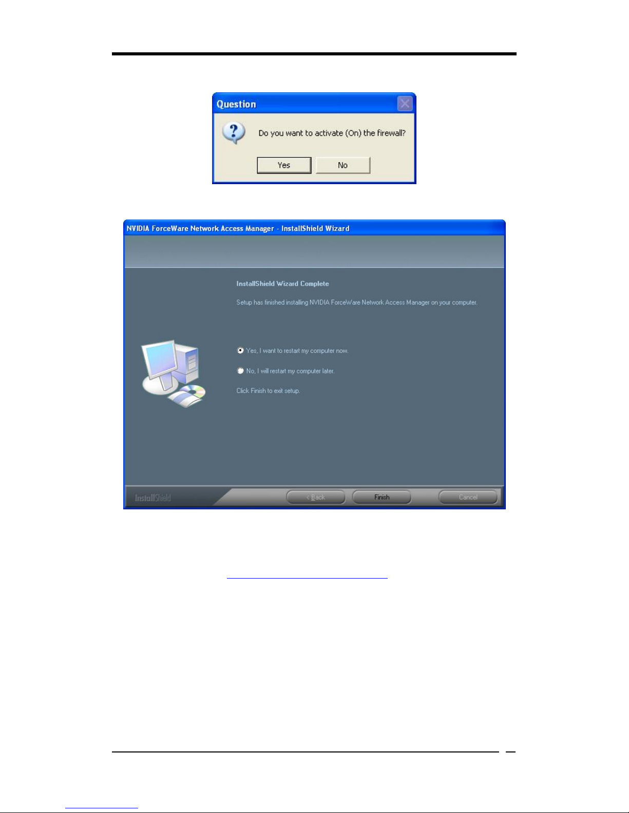
8.Clicking Yes is recommended.
9.Click Finish to restart your computer.
10.Once you restart the computer, the NVIDIA Firewall window as shown below
shall automatically show up. To learn how to use it to secure the network security,
please visit the website: http://www.nvidia.com/page/home for more detailed
intelligence.

Chapter 4
44
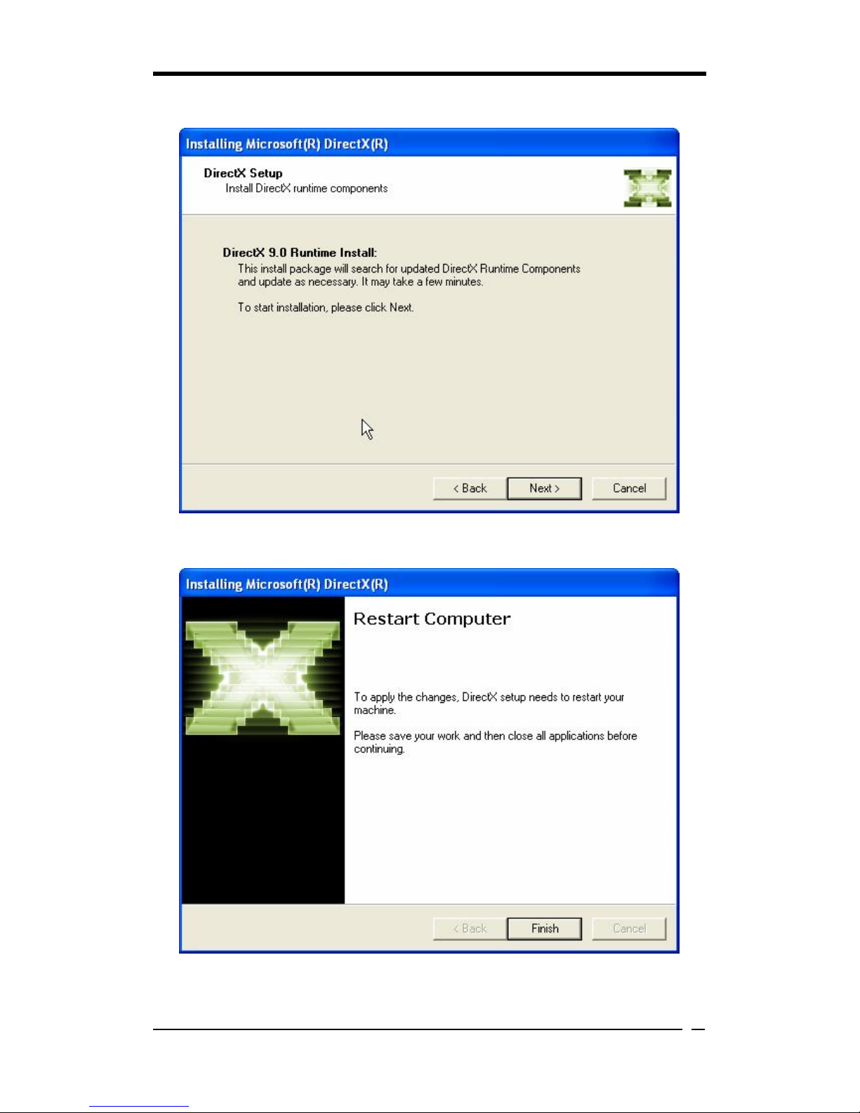
DirecX 9.0c Install
To install DireX 9.0c Install, please follow the instructions below.
How it works
1.Click DirecX 9.0c Install to enter the figure below, select I accept the agreement
after your study of license agreement, then click Next>.
Chapter 4
45
2.Click Next> to proceed.
3.Click Finish to restart computer.
Chapter 4
46
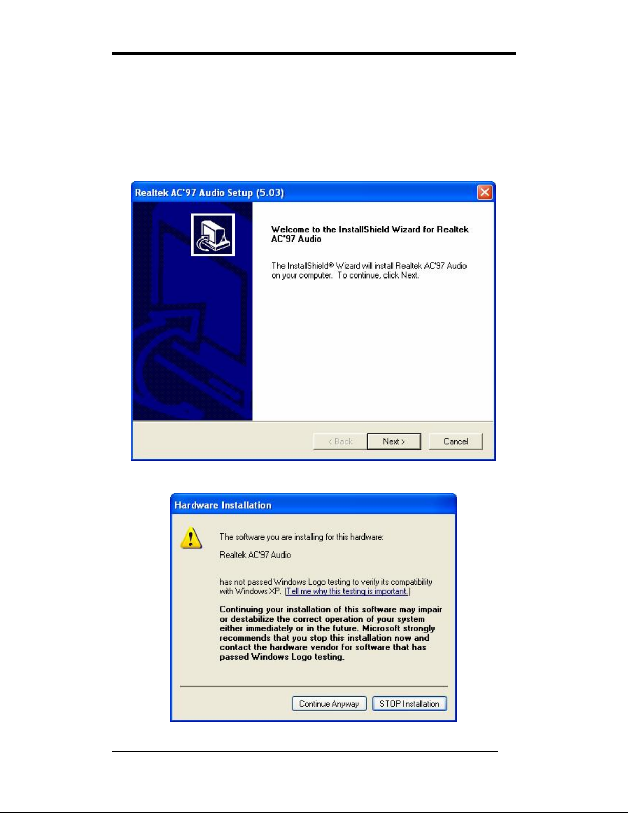
Realtek Codec Audio Driver
The item is responsible for installing Realtek Codec Audio controller and application.
To install this, please follow the instructions below.
How it works
1.Click Realtek Codec Audio Driver to enter the figure below, then click Next> to
continue.
2.Ignore the figure below then click Continue Anyway.
Chapter 4
47
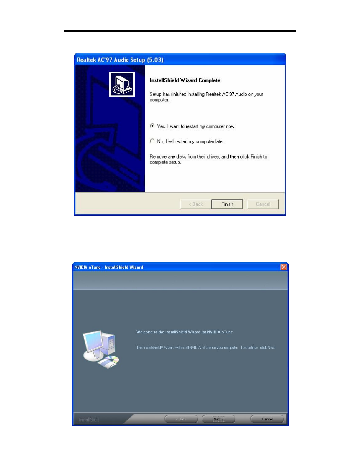
3.Select Yes, I want to restart my computer now then click Finish.
nTune Utility
To install this, please follow the instructions below.
How it works
1.Click Next> to proceed.
Chapter 4
48
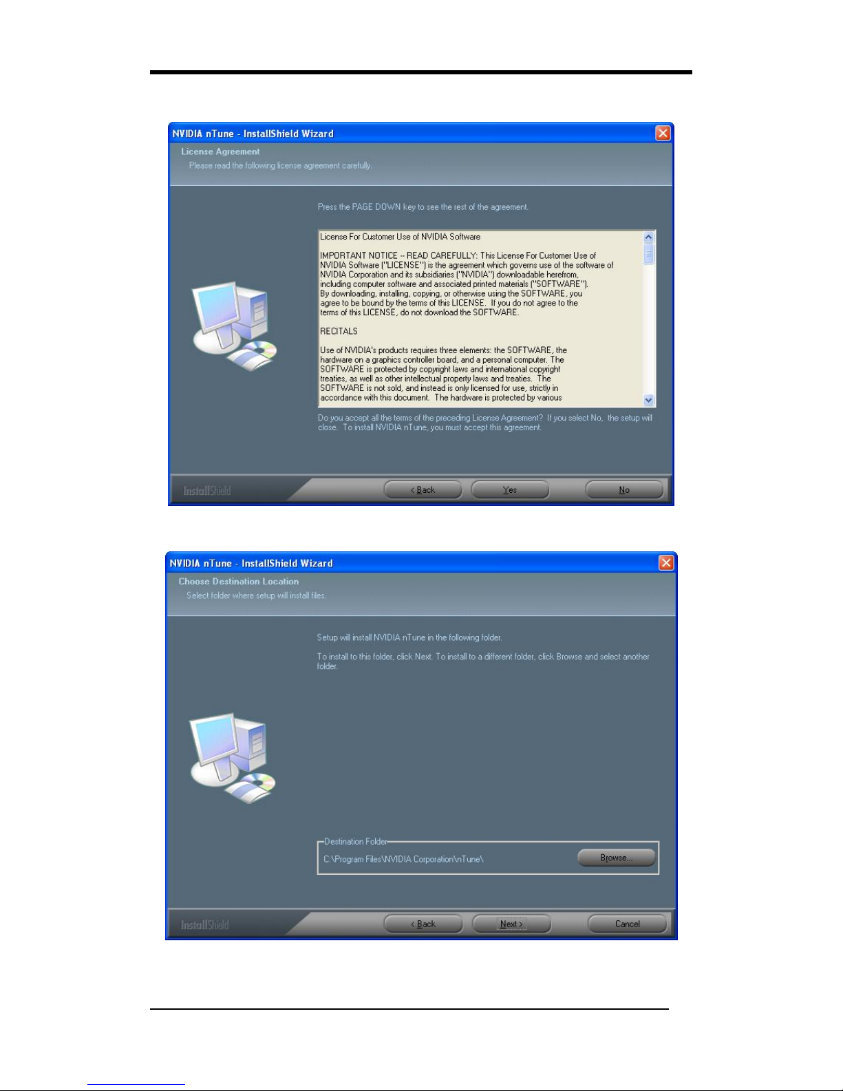
2.Click Yes after your study of license agreement.
3.Click Next> to proceed.

Chapter 4
49
4.Click Finish to complete the process.

Appendix
50
Appendix
A-1 Installing Windows 2000/XP on a SATA drive
Windows 2000:
(for the version 3.6 of driver)
1. Copy the SATA drivers from the driver CD. (CDROM:
Chipset\Nvidia\Nf4\Win2k_xp\Ide\Win2k→copy all the files except for the
Directory "raidtool") into a floppy disk
2. When the message "Press F6 if you need to install a third party SCSI or RAID
driver" shows up during Win2000/XP installation, press "F6"
3. Put the floppy disk in and wait for a little while.
4. Press "S" to install other drivers when next screen pops up.
5. Then the installation program will detect two drivers: "nVidia Raid class
driver(required)" and "nVidia nforce storage controller(required)"
6. First select "nVidia Raid class driver(required)" and press ENTER
7. Then select "nVidia nforce storage controller(required)" and press ENTER
8. Windows XP will ask you again whether to specify additional device, just press
ENTER
Windows XP:
(for the version 3.6 of driver)
1. Copy the SATA drivers from the driver CD. (CDROM:
Chipset\Nvidia\Nf4\Win2k_xp\Ide\Winxp→copy all the files except for the
Directory "raidtool") into a floppy disk
2. When the message "Press F6 if you need to install a third party SCSI or RAID
driver" shows up during Win2000/XP installation, press "F6"
3. Put the floppy disk in and wait for a little while.
4. Press "S" to install other drivers when next screen pops up.
5. Then the installation program will detect two drivers: "nVidia Raid class
driver(required)" and "nVidia nforce storage controller(required)"
6. First select "nVidia Raid class driver(required)" and press ENTER
7. Then select "nVidia nforce storage controller(required)" and press ENTER
8. Windows XP will ask you again whether to specify additional device, just press
ENTER

Note
51
NOTE
All rights are reserved for the products and corporate names/logos that appear in this manual
to their original owners.
WE reserve all rights to change this manual. All information is subject to change without
notice.

How To Contact CHAINTECH
52
How To Contact CHAINTECH
Please do not hesitate to contact us if you have any problem about our products. Any
opinion will be appreciated.
<Headquarter>
For Asia, Africa, Australia and Pacific
Island:
CHAINTECH COMPUTER CO., LTD
4F.-5, No.16, Jian 8th Rd., Zhonghe City,
Taipei County 235, Taiwan
Tel: +886-2-8226-8188
Fax: +886-2-8226-8199
URL: http://www.chaintech.com.tw
E-mail: sales@chaintech.com.tw
For France, Europe:
AELT COMPUTER
5 rue de Rome 93561 Rosny Sous Bois
Cedex France
Tel: +33-1-4855-5940
Fax: +33-1-4855-5942
URL: http://www.chaintech-france.com
E-mail: infos@chaintech-france.com
RMA: rma@chaintech-france.com
Technical Support:
support@chaintech-france.com
For Australia: (VGA only)
Protac International Computers Australia
Sydney Headquarters:
95 Derby St. Silverwater, NSW 2128
Tel: +61- 2-8748-8888
Fax: +61-2-8748-8801
http://www.protac.com.au
Melbourne:
Unit 7, 2 Sarton Rd, Clayton VIC 3168
Tel: +61-3-9560-7188
Fax: +61-3-9560-7288
For America:
CHAINTECH AMERICA CORP.
4427 Enterprise St. Fremont CA 94538, U.S.A.
Tel: +1-510-656-3648
Fax: +1-510-656-2297
URL: http://www.chaintechusa.com
E-mail (Sales): sales@chaintechusa.com
Technical Support:
Tel: +1-510-656-3607
Email:support@chaintechusa.com
For Korea:
CHAINTECH KOREA CO., LTD.
14F, Mi-Won B/D, Yeouido-Dong 43,
Youngdeunpo-Gu, Seoul, Korea
Tel: +82-2-6332-3377
Fax: +82-2-6332-3379
URL: http://www.chaintechkorea.com
E-Mail: sales@chaintechkorea.com
For China:
CHAINTECH, SHENZHEN
Room 301, Nanguang Building, No.1004,
Huafu Rd, Futian District,Shenzhen, China
518041
Tel: +86-755-8368-9072
Fax: +86-755-8368-9053
CHAINTECH, BEIJING
Room 3A05, 4 Floor, Unit No. B1, Longrange
World Office Building 2, No.18 Suzhou Street,
Haidian District, Beijing, China 100080
Tel: +86-10-6265-0087
Fax: +86-10-6262-0267
URL: http://www.chaintech.com.cn;
http://www.chaintech.cn
E-MAIL: service@chaintech.com.cn
 Loading...