


MPM800/MPT800
VIA PM800/VIA PT800 + VT8235
u-ATX Motherboard
User’s Guide
1

Chapter 1
2

Declaration of Conformity
According to 47 CFR, Parts 2 and 15 of the FCC Rules
The following designated product:
EQUIPMENT: MAINBOARD
is a Class B digital device that complies with 47 CFR Parts 2 and 15 of the FCC
Rules. Operation is subject to the following two conditions:
1. This device may not cause harmful interference.
2. This device must accept any interference received, including interference that
may cause undesired operation.
This declaration is given to the manufacturer:
CHAINTECH-EXCEL COMPUTER INC.
4427 Enterprise St. Fremont, CA 94538, U.S.A.
http://www.chaintechusa.com
Chaintech President: Simon Ho
Signature:
3

Chapter 1
100%
Federal Communications Commission Statement
This device complies with FCC Rules Part 15. Operation is subject to the following two conditions:
* This device may not cause harmful interference.
* This device must accept any interference received, including interference that may cause undesired operation.
This equipment has been tested and found to comply with the limits for a Class B digital device, pursuant to
Part 15 of the FCC Rules. These limits are designed to provide reasonable protection against harmful interference
in a residential installation. This equipment generates, uses, and can radiate radio frequency energy. If this
equipment is not installed and used in accordance with the manufacturer's instructions, it may cause harmful
interference to radio communications. However, there is no guarantee that interference will not occur in a
particular installation. If this equipment does cause harmful interference to radio or television reception, which can
be determined by turning the equipment off and on, the user is encouraged to try to correct the interference by one
or more of the following measures:
* Reorient or relocate the receiving antenna.
* Increase the separation between the equipment and receiver.
* Connect the equipment to an outlet on a circuit different from that to which the receiver is connected.
* Consult the dealer or an experienced radio/TV technician for help.
The use of shielded cables for connection of the monitor to the graphics card is required to assure
compliance with FCC regulations. Changes or modifications to this unit not expressly approved by the party
responsible for compliance could void the user's authority to operate this equipment.
Canadian Department of Communications Statement
This digital apparatus does not exceed the Class B limits for audio noise emissions from digital apparatuses
set out in the Radio Interference Regulations of the Canadian Department of Communications.
Manufacturer's Disclaimer Statement
The information in this document is subject to change without notice and does not represent a commitment
on the part of the vendor. No warranty or representation, either expressed or implied, is made with respect to the
quality, accuracy or fitness for any particular purpose of this document. The manufacturer reserves the right to
make changes to the content of this document and/or the products associated with it at any time without obligation
to notify any person or organization of such changes. In no event will the manufacturer be liable for direct, indirect,
special, incidental or consequential damages arising out of the use or inability to use this product or documentation,
even if advised of the possibility of such damages. This document contains materials protected by copyright. All
rights are reserved. No part of this manual may be reproduced or transmitted in any form, by any means or for any
purpose without expressed written consent of it's authors. Product names appearing in this document are mentioned
for identification purposes only. All trademarks, product names or brand names appearing in this document are
registered property of their respective owners.
Printed in Taiwan.
Jan 2004
OST-CONSUMER
RECYCLED PAPER
4

TABLE OF CONTENTS
Chapter 1 Introduction..............................................................6
1-1 Product Specifications..................................................................................6
1-2 Package Contents.........................................................................................7
1-3 Bakc Panel...................................................................................................7
1-4 Motherboard Layout.....................................................................................8
Chapter 2 Hardware Setup.....................................................9
2-1 PC D.I.Y. Assembly Instructions...................................................................9
2-2 自行組裝電腦之作業指導重點................................................................11
2-3 Français Instructions de montage du PC D.I.Y............................................13
2-4 Deutsch PC D.I.Y.-Montageanleitung.........................................................15
2-5 Самостоятельная сборка ПК ....................................................................17
2-6 PC D. I. Y. 조립 설명...............................................................................19
2-7 Connector and Jumper Settings...................................................................21
Chapter 3 BIOS Setup Program...........................................25
3-1 Standard CMOS Setup................................................................................25
3-2 Advanced BIOS Features............................................................................25
3-3 Advanced Chipset Features.........................................................................26
3-4 Integrated Peripherals.................................................................................26
3-5 Power Management Setup..........................................................................26
3-6 PNP/PCI Configurations.............................................................................26
3-7 Frequency/Voltage Control.........................................................................26
3-8 Load Fail-Safe Defaults..............................................................................26
3-9 Load Optimized Defaults............................................................................26
3-10 Supervisor Password & User Password Setting.........................................27
3-11 Save and Exit Setup..................................................................................27
3-12 Exit Without Saving.................................................................................27
Chapter 4 Driver Setup..........................................................28
4-1 VIA Driver Setup.......................................................................................28
4-2 Video Application......................................................................................28
4-3 DirectX 9.0.................................................................................................28
4-4 Audio Driver Setup....................................................................................28
4-5 LAN Driver Setup......................................................................................29
4-6 USB 2.0 Driver...........................................................................................29
5

Chapter 1
Chapter 1 Introduction
1-1 Product Specifications
CPU
- Supports Intel Socket 478 CPU with Hyper-Threading Technology
- Supports Intel Pentium 4 / Celeron system bus at 400/533/800 MHz
- Supports Intel Socket 478 Prescott CPU at 533/800 MHz
The use of the Intel® Pentium® 4 processor with 3.0 GHz core frequency, 1 MB
L2 cache and 800 MHz FSB (sSpec number SL7E4) is not recommended.
Chipset
- VIA PM800 + VT8235 (MPM800), VIA PT800 + VT8235 (MPT800)
supports Hyper-Threading Technology
Memory
- Two 184- pin DDR DIMMs up to 2GB
- Supports DDR266/333/400 memory
Expansion Slots
- One AGP slot for 8X/4X AGP
- Three 32-Bit PCI slots (v2.2 compatible)
Video Subsystem (MPM800)
- Integrated 128-bit UniChrome 2 GFX 2D/3D graphics accelerator
- Full frame DVD audio and video playback
- Shared system memory up to 64MB
5.1 Channel Audio
- With external high quality 5.1-channel AC’97 Codec
- Complete software driver supports for Windows OS
- Supports S/PDIF out
IDE
- Build-in VT8235 supports 2 UltraDMA-33/66/100/133 IDE Ports
FDD
- One FDD connector supports up to 2.88 MB
IEEE 1394(Optional)
- On-board VIA VT6307S IEEE 1394 Host Controller supports 2 IEEE1394
ports with Serial bus data rates of 100,200 and 400Mbps
- IEEE P1394a compliant and IEEE Std.1394-1995
6

USB 2.0
- Build-in VT8235 supports total 6 USB 2.0/1.1 ports
- Supports USB 2.0 High-Speed Device @480 Mb/s Transfer Rates
Fast Ethernet
- Supports 10/100Mb Fast Ethernet with external VIA VT6103 PHY
1-2 Package Contents
This product comes with the following components:
1. Motherboard x 1
2. 40-Pin UDMA-100 IDE Cable x 1
Blue to motherboard, Gray to Master and Black to Slave
3. 34-Pin floppy Disk Drive Cable x 1
Chapter 1
4. User’s Guide x 1
5. Driver CD x 1
1-3 Bakc Panel
a) MPM800
b) MPT800
7

Chapter 1
1-4 Motherboard Layout
8
Chapter 2
Chapter 2 Hardware Setup
2-1 PC D.I.Y. Assembly Instructions
1. Jumper Setting:
Set the CPU External Clock, Frequency Ratio and the CPU voltage according to the
instruction printed on the manual or silkscreen printed on the mainboard.
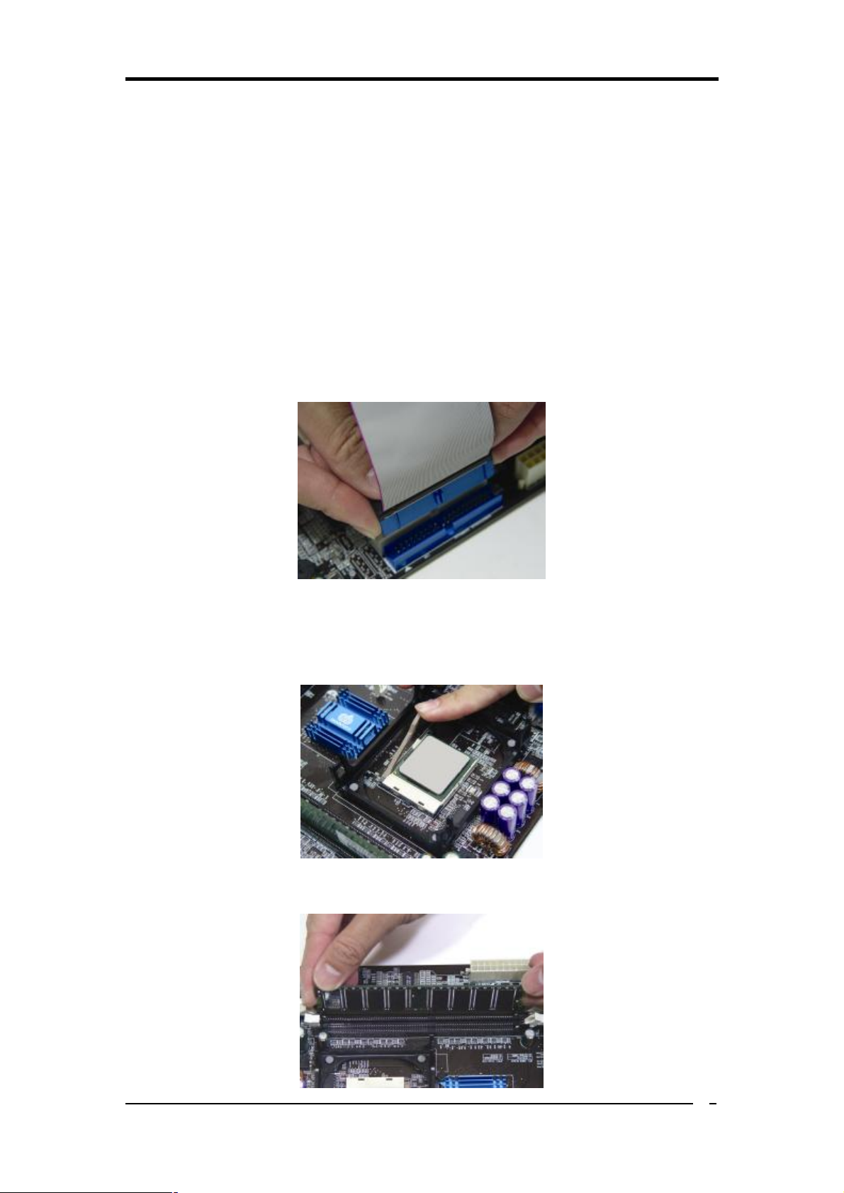
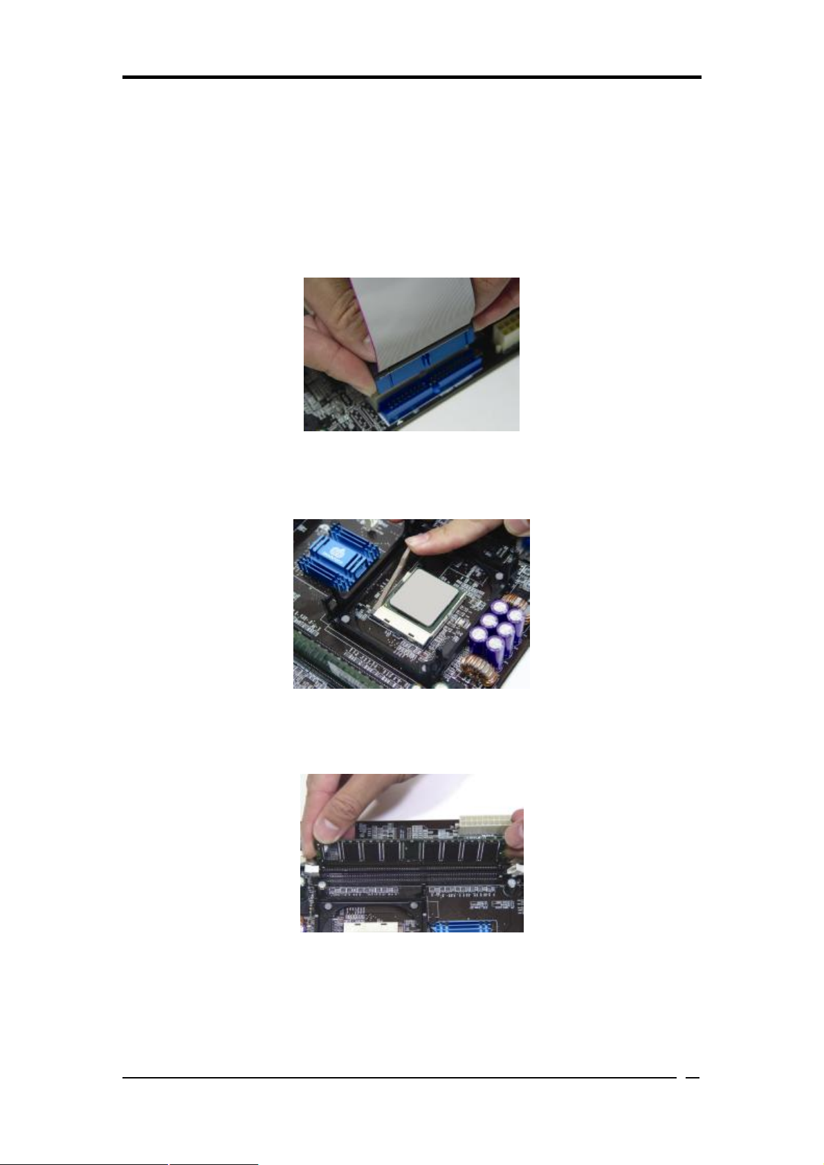
2. Installing FDD and IDE devices:
Aligned the red colored edge of the cable with the pin 1 of the drive connector on the
mainboard and gently attached it. Attach the other end of the cable by aligning the
colored edge to the pin 1 of the device connector. Make sure that all drives are
securely fastened.
3. Installing a CPU:
Socket 478-> Locate a noticeable notch in the CPU’s corner. This marking indicate
Pin 1 of the CPU. Gently insert the CPU with Pin 1 at the same corner of the socket
that contains the end of the lever.
4. Installing System Memory:
Push module downward until side clips are properly secure to the module.
9

Chapter 1
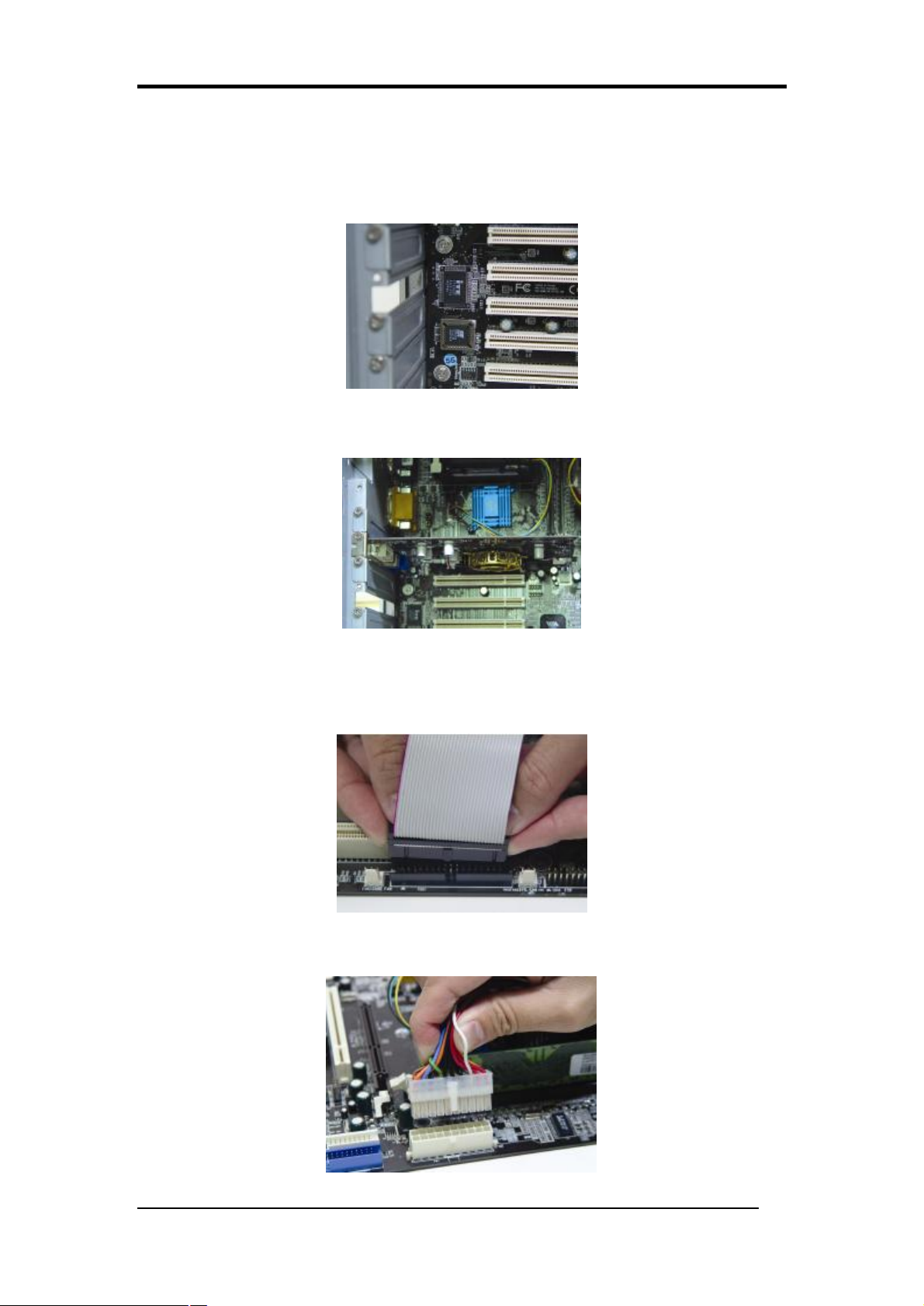
5. Mounting a Mainboard into a Chassis:
Use standoffs and screws to securely mount the mainboard and make sure that all the
mounting holes are properly screwed.
6. Adding an expansion card:
Gently fasten the card to the proper slot.
7. Connecting I/O ports and device connectors:
Simply plug the cable into the respective device port or connector as shown in the
manual or silkscreen printed on the mainboard.
8. Connecting the Power Supply Cables:
Plug in the ATX power cable to the mainboard power connector and make sure of the
cable latches.
10

Chapter 2
2-2 自行組裝電腦之作業指導重點
1. 主機板硬體組態設定:
依據使用手冊上面的指令或印刷在主機板上的文字來設定 CPU 外頻,倍頻及電
壓或其它設定。
2. 安裝 FDD 和 IDE 裝置:
將排線較長一端的排線插入主機板 IDE 插槽並且紅色線對準插槽的第一針腳
(Pin 1),檢視排線接頭是否完全插入插槽,同時排線較短的一端也依序插入軟碟
機,硬碟機等儲存裝置。
3. 安裝 CPU:
Socket 478 -> 將 CPU 的缺角對準 CPU 腳座的缺角並小心地將 CPU 插在腳座
上,按下旁邊的固定桿以固定 CPU。
4. 安裝系統記憶體:
先確定記憶體模組金手指的方向,慢慢插入記憶體插槽並小心地將記憶體模組往
下壓,直到插槽的固定卡榫卡住記憶體模組兩端的缺口。
11

Chapter 1
5. 主機板固定:
用銅柱及螺絲將主機板安裝在機殼底座並確定每個孔洞均已被鎖上,尤其注意主
機板底下不可有多餘的銅柱以避免造成短路。
6. 增加介面卡:
將介面卡(例 : 網路卡,音效卡等)插在適當的介面卡擴充插槽,並將卡上的鐵片
鎖緊在機殼上。
7. 連接 I/O 埠和其他設備的接頭:
適當地將排線插入各設備的插槽,記得必須將排線與插座的第一針腳互相對準,
請參照使用者手冊的主機板平面圖。
8. 連接電源供應器:
將電源接頭與主機板上之插座對準插入,並確定卡榫已緊扣。
12

Chapter 2
2-3 Français Instructions de montage du PC D.I.Y
1. Positionnement des cavaliers (jumpers)
Positionnez les cavaliers de la fréquence d’horloge externe du microprocesseur, du
rapport de fréquence et de la tension d’alimentation du microprocesseur, suivant les
instructions qui figurent dans le manuel ou qui sont sérigraphiées sur la carte mère.
2. Installation du disque dur et des périphériques IDE
Alignez le côté coloré en rouge du câble avec la broche n°1 du connecteur de la carte
mère, et fixez le câble en douceur. Raccordez l’autre extrémité du câble en alignant le
côté coloré en rouge du câble avec la broche n°1 du connecteur du périphérique.
Vérifiez que tous les périphériques sont correctement fixés.
3. Installation d’un microprocesseur
Microprocesseur sur support Socket 478 ou A
Repérez l’encoche qui se trouve dans l’un des coins du microprocesseur. Cette
encoche indique la broche n°1 du microprocesseur. Insérez en douceur le
microprocesseur dans son support, en plaçant la broche n°1 du côté du support où se
trouve l’extrémité du levier de blocage.
4. Installation de la mémoire vive
Poussez la barrette dans son logement jusqu’à ce que les deux clips latéraux soient
correctement bloqués par le support module.
13

Chapter 1
5. Montage d’une carte mère dans son châssis
A l’aide des jauges d’espacement et des vis fournies, fixez fermement la carte mère
dans son emplacement, et vérifiez que tous les trous destinés à la fixation sont utilisés
et les vis sont correctement serrées.
6. Ajout d’une carte d’extension
Fixez avec précaution la carte dans le logement adapté.
7. Raccordement des ports d’E/S et des connecteurs des périphériques
Branchez simplement le câble dans le port ou le connecteur du périphérique concerné,
suivant les instructions qui figurent dans le manuel ou qui sont sérigraphiées sur la
carte mère.
8. Raccordement des câbles de l’alimentation électrique
Raccordez le câble d’alimentation ATX au connecteur d’alimentation de la carte mère,
et vérifiez qu’ils sont bien verrouillés en place.
14

2-4 Deutsch PC D.I.Y.-Montageanleitung
1. Steckbrücken Konfigureren
Die Anweisungen zum Einstellen des externen Prozessortakts, der Taktfrequenz
und der Prozesorspannung finden Sie im Hand buch oder direct auf dem
Motherboard.
2. Disketten- und Festplattenlaufwerke Installieren
Schließen Sie die rot markierte Kabelseite an Stift 1 des Laufweksanschlußes auf
dem Motherboard an. Bringen Sie das andere Kabelende am GeräteanSchluß.
Richten Sie dabei die rot markierte Kabelseite mit Stift 1 aus.
Überprüfen Sie den stabilen Sitz aller Laufwerke Kabel.
Chapter 2
3. Prozessor Installieren
Socket 478 ->Der Prozessor ist an einer Stelle eingekerbt. Mit diesser Kerbe wird
Stift 1 des Prozessors gekennzeichnet. Setzen Sie den Prozessor vorsichtig in den
Sockel ein, und richten Sie dabei Stift 1 mit dem Hebelende aus.
4. Arbeitsspeicher einsetzen
Drücken Sie das Modul nach unten, bis die seitlichen Steckplatzhalterungernim
Modul eiratsen.
15

Chapter 1
5. Motherboard im Gehäuse montieren
Verwenden Sie das modul nach Schraubenund Abstandhalter, um das Motherboard stabil
im Gehäuse zu montieren. Achten Sie darauf, daß sämtliche Montagöffnungen korrekt
miet einer Schraube versekhen werden.
6. Steckkarte einbauen
Führen Sie die Karte vorsichtig in einen geeingneten Steckplatz ein.
7. Vo- und Geräteanschluße verbinden
Verbinden Sie das Kabel mit dem ensprechenden Geräteanschluß. Folgen Sie
dabei den Anweisungen im Handbuch oder direkt auf dem Motherboard.
8. Netzkabel anschließen
Verbinden Sie das ATX-Netzkabel korrekt mit dem Netzanschluß auf dem
Motherboard.
16

2-5 Самостоятельная сборка ПК
1. Установка перемычек
Установите параметры Вашего таймера ЦПУ, значение частоты и
напряжение ЦПУ согласно инструкциям, приведенным в руководстве, или
надписям на системной плате.
2. Установка Накопителя на гибких дисках и IDE устройств
Совместите кромку красного цвета кабеля и PIN1 разъема накопителя на
системной плате, затем аккуратно соедините их. Присоедините другой конец
кабеля к разъему накопителя, совместив кромку красного цвета с PIN1
накопителя. Убедитесь, что все накопители правильно подсоединены.
Chapter 2
3. Установка ЦПУ
Процессоры Socket 478
Найдите отметку у одного из углов. Данная маркировка указывает на PIN1
процессора. Аккуратно вставьте ЦПУ, совместив PIN1 процессора с
соответствующим углом гнезда, расположенным у окончания рычага.
4. Установка системной памяти
С небольшим нажатием вставьте модули в банки до момента надежного
закрепления модулей зажимами.
17

Chapter 1
5. Монтаж системной платы на шасси
Для надежного монтажа системной платы используйте крепления и винты.
Убедитесь, что все монтажные отверстия закреплены винтами.
6. Установка карт расширения
Аккуратно установите карту в соответствующий слот
7. Подсоединение портов ввода/вывода и разъемов устройств
Подсоедините кабель к соотве5тствующему порту или разъему согласно
инструкциям, приведенным в руководстве или напечатанным на системной
плате.
8. Подсоединение кабелей источника питания
Подсоедините кабель питания ATX к разъему питания системной платы и
убедитесь в надежности крепления
18
Chapter 2
2-6 PC D. I. Y. 조립 설명
1.점퍼설정
매뉴얼이나 메인보드에 나와있는 설정방법을 참고하여 CPU 의 외부클럭,
주파수, 전압 등을 설정합니다.
2. 메인보드 장착
드라이버를 이용하여 케이스에 정확하게 메인보드를 장착합니다.
3. CPU 장착
CPU 의 모서리를 보면 표시가 되어있습니다. 이 부분이 1번 핀입니다. 이
부분을 메인보드의 CPU 소켓에 맞추어 CPU 를 장착합니다.
4. 메모리 장착
메모리의 금색부분이 보이지 않을 때까지 메모리 슬롯에 메모리를
꼽습니다. 완벽하게 꽂히면 슬롯 옆에 있는 고정핀이 자동으로 올라옵니다.
19
Chapter 1
5. 플로피 디스크, 하드디스크 케이블 연결
케이블의 1번선은 빨간색입니다. 이 선을 기준으로 하여 메인보드의
1 번핀에 정확하게 장착합니다. 커넥터가 확실하게 연결될 수 있도록
하십시오.
6. 외부 카드의 장착
비디오카드 및 다른 외부 장착용 카드를 장착합니다.
7. I/O 포트, 기타장치 연결
매뉴얼이나 메인보드에 나와있는 설정방법을 참고하여 I/O 장치와
기타장치를 연결합니다.
8. 파워 써플라이 케이블 연결
ATX 파워케이블을 메인보드에 연결합니다. 감사합니다.
20

Chapter 2
2-7 Connector and Jumper Settings
Connectors are used to link the system board with other parts of the system, including
power supply, keyboard, and the various controllers on the front panel of the system
case.
The power supply connector is the last connection to be made while
installing a motherboard. Before connecting the power supply, please
make sure it is not connected to the power source.
All cables come with a security-proof.
PW 1 / 3 (ATX Power Supply Connector):
The power cord leading from the system's power supply to the
external power source must be the very last part connected when
assembling a system. The ATX power supply provides a single
20-pin connector interface, which incorporates standard +/-5V,
+/-12V, optional 3.3V and Soft-power signals. The Soft
power signal, a 5V trickle supply is continuously supplied
when AC power is available. When the system is in
Soft-Off mode, this trickle supply maintains the system in
its minimum power state.
The ATX 12V power supply has a new +12V (4-pin) and
+5V / 3.3V (6-pin) auxiliary power connector to enable the delivery of more +12
VDC and + 5/ 3.3V VDC current to the motherboard.
Power-On By Modem:
While in Soft-Off state, if an external modem ring-up signal is detected, the system
will be activated and therefore can be remotely accessed. You may enable this
function in BIOS's Power Management Setup menu. (See section 3. 5)
Blinking LED in Suspend Mode:
While in Suspend mode, the LED light on the front panel of your computer will flash.
Suspend mode is entered by pressing the Green Override Power Button on your ATX
case, or by enabling the Power Management and Suspend Mode options in BIOS's
Power Management menu. (See section 3.5)
Poly-fuse Over Current Protection:
The poly-fuse protects the system from dangerous voltages that the system might be
21
Chapter 1
exposed to via keyboards or USB connectors. In case of such an exposure, the
poly-fuse will immediately be disconnected from the circuit just like a normal fuse.
After being disconnected for a certain period of time, the poly-fuse will return to its
normal state and the keyboard or USB connector can function properly again. Unlike
conventional fuses, the poly-fuse will not need to be replaced, relieving users from
such inconveniences.
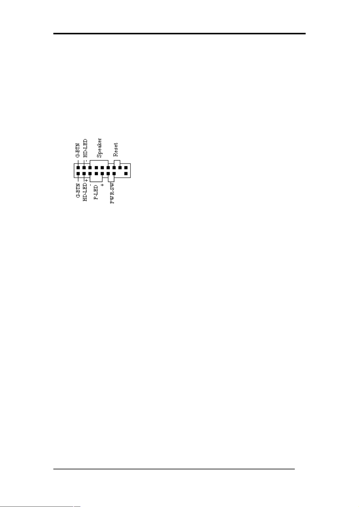
CN1A (Front Panel Connector):
PWR-SW (Over-ride Power Button Connector):
The power button on the ATX chassis can be used as a
normal power switch as well as a device to activate the
Advanced Power Management Suspend mode. This is
a power-saving mode used for saving electricity when
the computer is idle for long periods of time. The
Soft-OFF by PWR-BTTN function in BIOS’s Power
Management Setup menu must be set to [Delay 4 Sec.]
to activate this function.
When the Soft-OFF by PWR-BTTN function is enabled, pressing the power
button rapidly will switch the system to Suspend mode. Any occurrence of
external activities such as pressing any keys on the keyboard or moving the
mouse will bring the system back to Full-On. Pushing the button while in
Full-On mode for more than [4 seconds] will switch the system completely off.
See Over-ride Power Button Operation diagram.
1. P-LED (Power LED Connector):
The power indicator LED shows the system's power status. It is important to
pay attention to the correct cable and pin orientation (i.e. Be careful not to
reverse the order of these two connectors.)
2. G-BTN (Green Button Switch):
Some ATX cases provide a Green button switch, which is used to put the
system in Suspend mode. While in Suspend mode, the power supply to the
system is reduced to a trickle, the CPU clock is stopped, and the CPU core is
in its minimum power state. The system is activated whenever the keyboard or
mouse is touched. The system will resume in various ways as defined by
Power Management Setup screen in BIOS.
3. RESET (System Reset Switch Connector):
This connector should be connected to the reset switch on the front panel of
the system case. The reset switch allows you to restart the system without
turning the power off.
4. SPEAKER (Speaker Connector):
22
Chapter 2
This 4-pin connector connects to the case-mounted speakers.
5. HD-LED (IDE - Activity LED Connector):
The IDE- activity LED lights up whenever the system reads/writes to the IDE
devices.
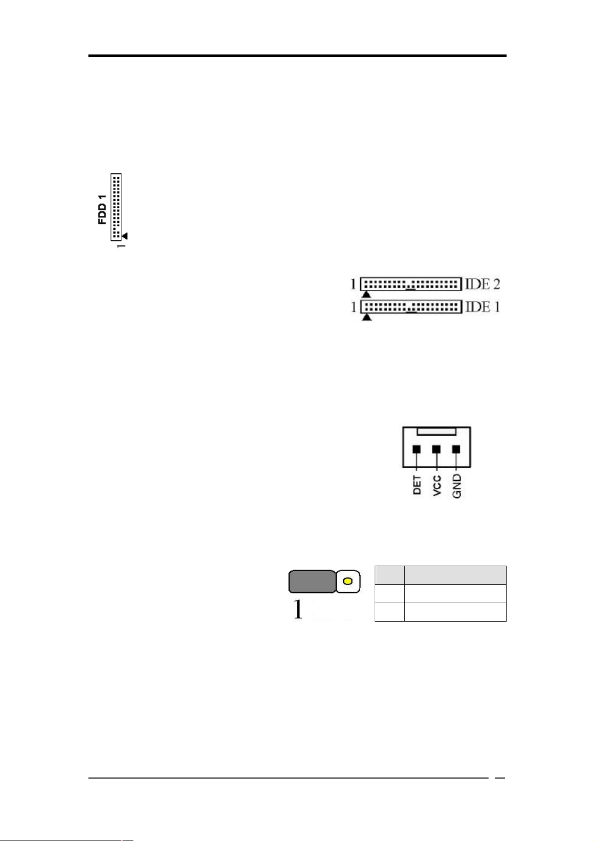
FDD1 (Floppy Connector):
The motherboard provides a standard floppy disk drive connector that
supports 360K, 720K, 1.2M, 1.44M and 2.88M floppy disk types. It is
connected to a floppy disk drive of 34 pins.
IDE 1/2 (IDE Hard-Disk Connector):
The motherboard has a 32-bit Enhanced PCI IDE
and Ultra ATA66/100/133 controller that provides
PIO mode 0~4, Bus Master, and Ultra
ATA66/100/133 function. This connector is used for connecting 40 pins of ATAPI
devices.
IDE 1 only connects two IDE devices. (Primary Master/Slave)
IDE 2 only connects two IDE devices. (Secondary Master/Slave)
FAN1/2/3 (CPU/System/ North bridge Connectors):
The board's hardware management is able to detect the CPU
and system fan speed in rpm (revolutions per minute). The
wiring and plugging may vary depending on the manufacturer.
On standard fans, the red is positive (+12V), the black is
ground, and the yellow wire is the rotation signal. Connect the
north-bridge cooling fan to FAN4.
JP1 (CMOS Clear Jumper):
There is a CMOS RAM on board
Pin
that has a power supply from
external battery to keep the data and
system configuration. To clear the
1-2 Normal (default)
2-3 Clear CMOS Data
contents of the CMOS, please follow the steps below.
Definition
1. Disconnect the system power supply from the power source.
2. Set the jumper cap at location [2-3] for <5 seconds>, and then set it back to the
default position.
3. Connect the system's power and then start the system.
4. Enter BIOS's CMOS Setup Utility and choose Load Optimized Defaults.
Type [Y] and then press [Enter] to continue.
23
Chapter 1
5. Set the system configuration in the Standard CMOS Setup menu.
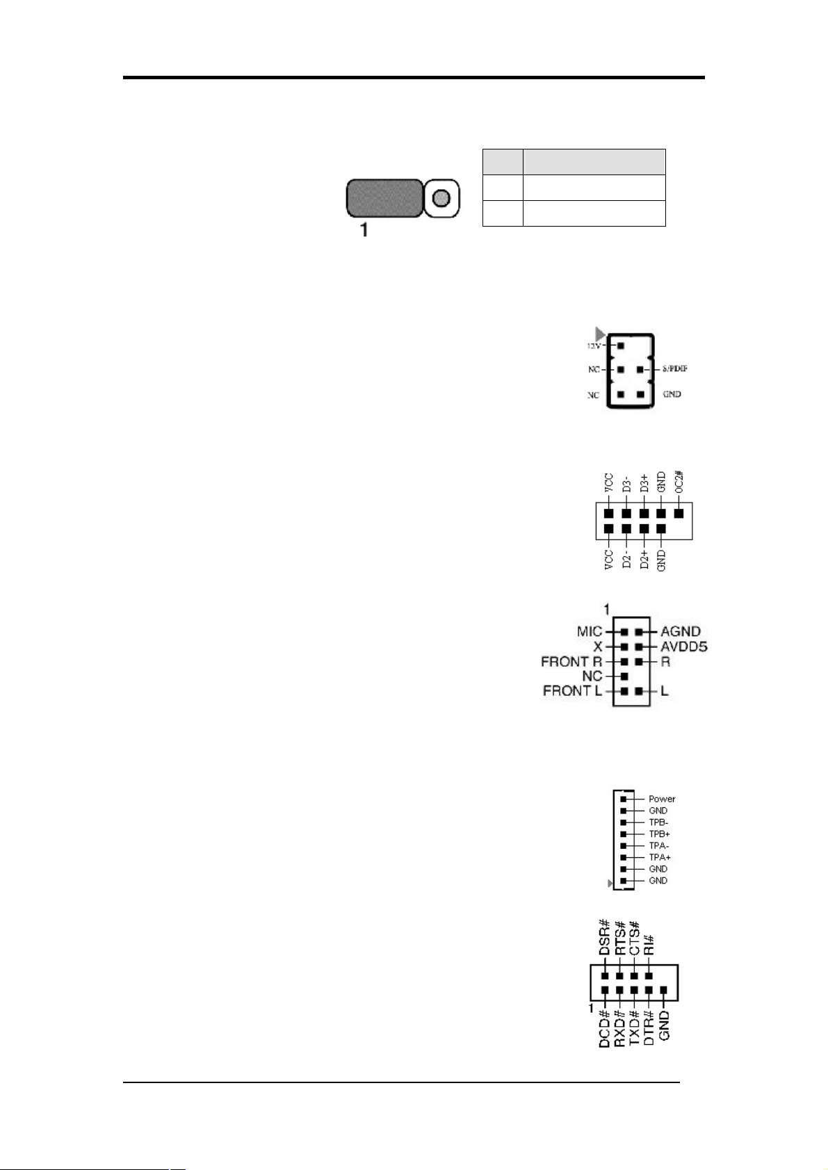
JP6 (Power On by USB 2/3):
Pin
Definition
JP6 -> USB 2/3
An USB keyboard hot key or
an USB mouse-click can
1-2 Disable (default)
2-3
Enable
activate this board. To use this function, select a hot key of your
choice at the USB Resume from S3 option under Wake Up Events in the BIOS's
Power On Management screen. You must also set this jumper's cap to pins 2-3 to use
this function.
CN13 (S/PDIF Connector)
To enable the S/PDIF function this connector must be
connected to a S/PDIF bracket.
CN23A / 23B (USB Connector for USB 4/5 and 6/7):
USB Port 4/5 à CN23A USB Port 6/7 à CN23B
If you want to use a USB Keyboard, you must enable the USB
keyboard support function in BIOS's Integrated Peripherals menu
(See Section 3.4). This board contains a USB Host controller and
a root hub with two connectors is also included for an optional
USB Adaptor (USB 4/5 and 6/7).
CN24 (Front Audio Connector):
This connector gives you the option of a front-panel
audio-jack cable ext. to be plugged into a special
custom-designed system case.
Simply remove the two jumper caps at pins [5-6] and [9-10]
then plug it into the (optional) cable ext. connector. Pins [5-6] and [9-10] are shorted
(default) to enable the back-panel audio function.
CN26/26A (IEEE1394 Connector)
Attach the IEEE 1394 serial connector cable to the IEEE 1394
bracket.
COM 2 (Serial port / COM Headers)( MPM800 only)
This 9-pin connector is used for connecting a serial-port ribbon
cable to an additional COM port.
24
Chapter 3
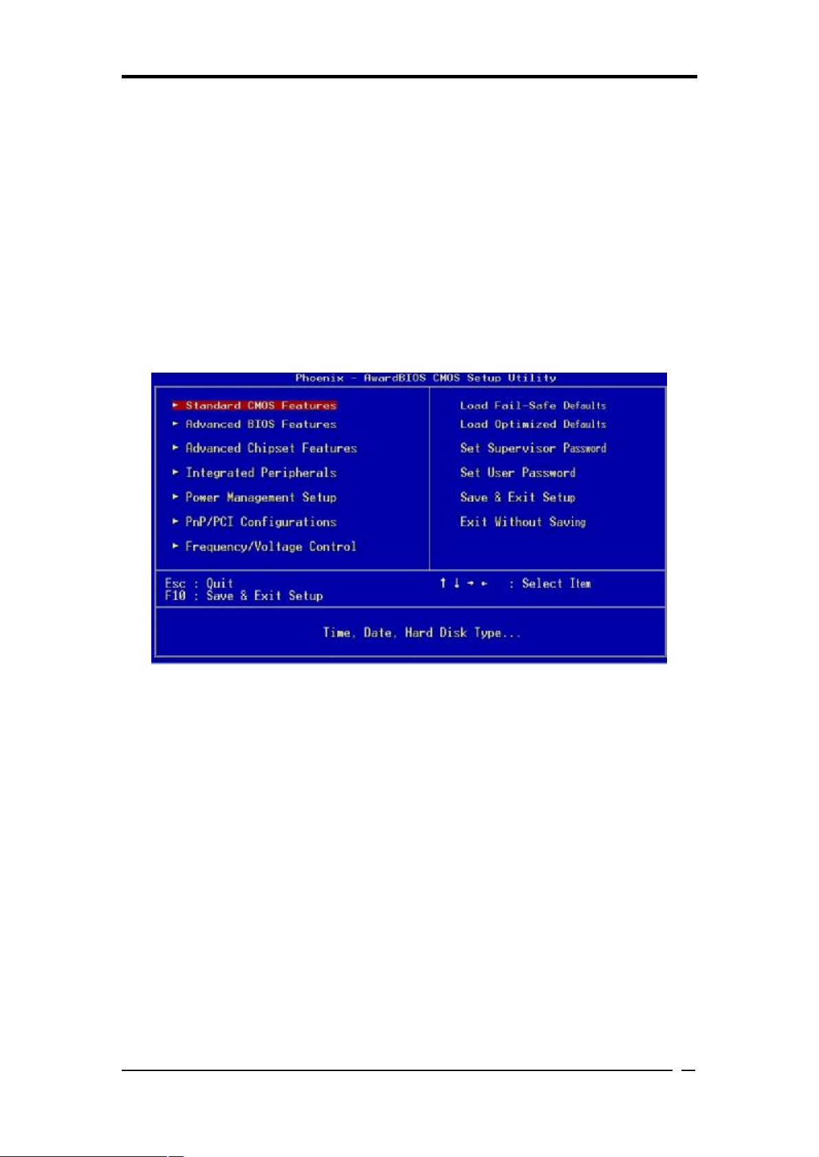
Chapter 3 BIOS Setup Program
Phoenix-Award BIOS ROM has a built-in setup program that allows users to modify
the basic system configuration. This information is stored in CMOS RAM so that it
can retain the setup information even when the power is turned off. Press [Delete]
when you Power on or Reboot the computer system..The primary screen as shown in
Figure 3-1 is a list of the menus and functions available in the setup program. Select
the desired item by using arrow keys and press [Enter] to make the changes.
Operating commands are located at the bottom of this and all other BIOS screens.
When a field is highlighted, on-line help information is displayed on the right side of
the screen.
Figure 3-1 Setup Program Initial Screen
3-1 Standard CMOS Setup
The Standard CMOS Setup allows users to configure system components such as
hard-disk drive, floppy-disk drive and video display as well as date, time and boot up
error signaling. This configuration menu should be changed when installing a
motherboard for the first time, or changing hardware such as HDD, FDD, and video
display in your system, or when the CMOS data was lost or corrupted.
3-2 Advanced BIOS Features
By choosing the Advanced BIOS Features option from the CMOS Setup Utility menu
(Figure 3-1), the screen that lists the manufacturer's default values for the
motherboard is displayed.
25

Chapter 3
3-3 Advanced Chipset Features
In this section a list of advanced chipset functions are provided to users. By choosing
the [Advanced Chipset Features] option from the CMOS Setup Utility menu (Figure
3-1), the screen below is displayed. This sample screen contains the manufacturer's
default values for the motherboard.
3-4 Integrated Peripherals
This section provides information on setting up the peripheral devices.
3-5 Power Management Setup
This section provides information on the Green PC power management functions.
3-6 PNP/PCI Configurations
This section provides IRQ and DMA settings information.
3-7 Frequency/Voltage Control
This section allows users to adjust the frequency/voltage control of the motherboard.
3-8 Load Fail-Safe Defaults
Load Fail-Safe Defaults loads the default BIOS values directly from the CMOS
Setup Utility menu (Figure 3-1). If user-defined BIOS settings are corrupted and
therefore unusable, these defaults will be loaded automatically when you turn on the
computer.
3-9 Load Optimized Defaults
Load Optimized Defaults loads the default system values directly from the CMOS
Setup Utility menu (Figure 3-1). If user-defined BIOS settings are corrupted and
therefore unusable, these defaults will be loaded automatically when you turn on the
computer.
26

Chapter 3
g set, the user password
3-10 Supervisor Password & User Password Setting
There are four different variables that control password settings. The first two are
located under the Security Option function in BIOS Features Setup Menu (Figure 3-3).
When the Security Option function is set to Setup, a password is required to enter
BIOS and change BIOS settings. When the Security Option function is set to System,
a password is required to enter both BIOS and computer's operating system (For
example, Windows 98) found on the boot drive.
The third and fourth variables are user password and supervisor password selected in
COMS Setup Utility (Figure 3-1). The main purpose of separating users and
supervisors is to allow only the supervisor to have control over the BIOS settings. The
user, on the other hand, is only allowed to access computer's operating system and
change the user password in BIOS.
When there is no supervisor password bein
controls access to all BIOS settings.
3-11 Save and Exit Setup
If you select this and type [Y] followed by [Enter], the values entered in the setup
utilities will be recorded in the CMOS memory of the BIOS chip.
3-12 Exit Without Saving
Selecting this option and pressing [Y] followed by [Enter] lets you exit the Setup
program without recording any new values or changing old ones.
27

Chapter 4
Chapter 4 Driver Setup
Insert the support CD that come with your motherboard into your CD-ROM driver
or double-click the CD drive icon in [My computer] to enter the setup screen.
4-1 VIA Driver Setup
1. Click [VIA Service Pack].
2. Click [Next >] to start software installation.
3. Click [Yes >] to continue.
4. Select either Normal or Quick Installation and click [Next >] to continue.
5. Select the driver types and click [Next >] to continue.
6. Select [Install VIA PCI IDE Bus Driver] and click [Next >] to proceed.
7. Install AGP driver and click [Next >] to continue.
8. Select [Yes, I want to restart my computer now] or [No, I will restart my
computer later] and then click [OK] to complete the setup process.
4-2 Video Application
1. Click [Video Application].
2. Click [Next >] to begin the installation process.
3. Click [Next >] to continue.
4. Select [Yes, I want to restart my computer now] or [No, I will restart my
computer later] and then click [OK] to complete the setup process.
4-3 DirectX 9.0
1. Click [DirectX 9.0].
2. Accept the license agreement and click [Next >] to proceed.
3. Click [Next >] to continue.
4. Click [Finish >] to complete the setup process.
4-4 Audio Driver Setup
This section provides information on installing audio devices by choosing
[Audio Driver] from the Setup Driver menu.
1. Select [Audio driver] to begin the software installation
2. Click [Next >] to begin the installation process.
3. Click [Next >] to continue.
4. Please select a folder where the program will be installed and click [Next >]
28

to proceed.
5. Please select one folder from existing list of folders and click on [Next >] to
proceed.
6. Click [Next >] to proceed.
7. Select [Yes, I want to restart my computer now] or [No, I will restart my
computer later] and then click [OK] to complete the setup process.
4-5 LAN Driver Setup
1. Click [LAN Driver]
2. Click [Next >] to begin the installation process.
3. Click [Finish] to complete the setup process.
4-6 USB 2.0 Driver
Chapter 4
1. Click [USB 2.0 Driver] to start the installation.
2. Click [Next >] to begin the installation.
3. Select [Install USB Driver] and click [Next >] to proceed.
4. Click [Yes] to accept the license agreement.
5. Click [OK] to proceed.
6. Select [Print to File] and click [Next >] to continue.
7. Click [OK] to continue.
8. Select [Yes, I want to restart my computer now] or [No, I will restart my
computer later] and then click [OK] to complete the setup process.
29

Note
NOTE
All rights are reserved for the products and corporate names/logos that
appear in this manual to their original owners.
CHAINTECH reserves all the rights to change this manual. All
information is subject to change without notice.
30

How to Contact CHAINTECH
How To Contact CHAINTECH
Please do not hesitate to contact us if you have any problem about our products. Any
opinion will be appreciated.
For Asia, Africa, Australia and Pacific
Island:
CHAINTECH COMPUTER CO., LTD
No. 7-1, Chung Shin Rd., Tu Cheng,
Taipei Hsien, Taiwan, ROC.
Tel: +886-2-2268-9998
Fax: +886-2-2269-7510
URL: http://www.chaintech.com.tw
E-mail: sales@chaintech.com.tw
For France:
AELT COMPUTER
5 rue de Rome 93561 Rosny Sous Bois
Cedex France
Tel: 33-1-4855-5940
Fax: 33-1-4855-5942
URL: http://www.chaintech-france.com
E-mail: infos@chaintech-france.com
For Australia: (VGA only)
Protac International Computers Australia
Sydney Headquarters:
95 Derby St. Silverwater, NSW 2128
Tel: 61- 2-8748-8888
Fax: 61-2-8748-8801
http://www.protac.com.au
Melbourne:
Unit 7, 2 Sarton Rd, Clayton VIC 3168
Tel: 61-3-9560-7188
Fax: 61-3-9560-7288
For Image It/ Promagic 6.0 software
information and technical support:
Wasay Software Technology
5F, No 323, Sec 1,Fushing South Rd.,
Taipei, Taiwan 106 R.O.C
Tel : + 886-2-2705-7599
Fax : +886-2-2705-9555
Email : service@wasay.com
URL: http://www.wasay.com
For Italy and Greece:
CELT Computer s.r.l.
Via Private Mulino N.3-20090
Buccinasco, Milano,Italy
Tel: +39-02-4510-1355
Fax: +39-02-4510-1354
URL: http://www.chaintech.com.tw
E-MAIL: celt@libero.it
For Europe:
CHAINTECH EUROPE B.V.
Coenecoop 620 2741 PV WADDINXVEEN,
THE NETHERLANDS
Tel: +31-182-623-960
Fax: +31-182-623-969
URL: http://www.chaintech.nl
Technical support
E-mail: support@chaintech.nl
For America:
CHAINTECH AMERICA CORP.
4427 Enterprise St. Fremont CA 94538,
U.S.A.
Tel: +1-510-656-3648
Fax: +1-510-656-2297
URL: http://www.chaintechusa.com
E-mail (Sales): sales@chaintechusa.com
Technical Support:
Tel: +1-510-656-3607
E-mail:support@chaintechusa.com
For China
CHAINTECH, SHENZHEN
Room 301, Nanguang Building, No.1004,
Huafu Rd, Futian District,Shenzhen, China
518041
Tel: +86-755-8368-9072
Fax: +86-755-8368-9053
CHAINTECH, BEIJING
403, Building A, No.118, Zhichun Rd,
Haidian District, Beijing, China 100086
Tel: +86-10-6265-0087
Fax: +86-10-6262-0267
URL: http://www.chaintech.com.cn;
http://www.chaintech.cn
E-MAIL: service@chaintech.com.cn
For Korea:
CHAINTECH KOREA CO., LTD.
14F, Mi-Won B/D, Yeouido-Dong 43,
Youngdeunpo-Gu, Seoul, Korea
Tel: +82-2-6332-3377
Fax: +82-2-6332-3379
URL: http:// www.chaintechkorea.com
E-Mail: sales@chaintechkorea.com
31
 Loading...