


Declaration of Conformity
According to 47 CFR, Parts 2 and 15 of the FCC Rules
The following designated product:
EQUIPMENT: MAINBOARD
is a Class B digital device that complies with 47 CFR Parts 2 and 15 of the FCC
Rules. Operation is subject to the following two conditions:
1. This device may not cause harmful interference.
2. This device must accept any interference received, including interference that
may cause undesired operation.
This declaration is given to the manufacturer:
CHAINTECH AMERICA CORP.
4427 Enterprise St. Fremont, CA 94538, U.S.A.
http://www.chaintech.com.tw
Chaintech President: Simon Ho
Signature:

VIA K8T890 + VT8237R
u-ATX Motherboard
User’s Guide

Federal Communications Commission Statement
1 0 0 %
This device complies with FCC Rules Part 15. Operation is subject to the following two conditions:
* This device may not cause harmful interference.
* This device must accept any interference received, including interference that may cause undesired operation.
This equipment has been tested and found to comply with the limits for a Class B digital device, pursuant
to Part 15 of the FCC Rules. These limits are designed to provide reasonable protection against harmful
interference in a residential installation. This equipment generates, uses, and can radiate radio frequency energy.
If this equipment is not installed and used in accordance with the manufacturer's instructions, it may cause
harmful interference to radio communications. However, there is no guarantee that interference will not occur in
a particular installation. If this equipment does cause harmful interference to radio or television reception, which
can be determined by turning the equipment off and on, the user is encouraged to try to correct the interference
by one or more of the following measures:
* Reorient or relocate the receiving antenna.
* Increase the separation between the equipment and receiver.
* Connect the equipment to an outlet on a circuit different from that to which the receiver is connected.
* Consult the dealer or an experienced radio/TV technician for help.
The use of shielded cables for connection of the monitor to the graphics card is required to assure
compliance with FCC regulations. Changes or modifications to this unit not expressly approved by the party
responsible for compliance could void the user's authority to operate this equipment.
Canadian Department of Communications Statement
This digital apparatus does not exceed the Class B limits for audio noise emissions from digital
apparatuses set out in the Radio Interference Regulations of the Canadian Department of Communications.
Manufacturer's Disclaimer Statement
The information in this document is subject to change without notice and does not represent a
commitment on the part of the vendor. No warranty or representation, either expressed or implied, is made with
respect to the quality, accuracy or fitness for any particular purpose of this document. The manufacturer reserves
the right to make changes to the content of this document and/or the products associated with it at any time
without obligation to notify any person or organization of such changes. In no event will the manufacturer be
liable for direct, indirect, special, incidental or consequential damages arising out of the use or inability to use
this product or documentation, even if advised of the possibility of such damages. This document contains
materials protected by copyright. All rights are reserved. No part of this manual may be reproduced or
transmitted in any form, by any means or for any purpose without expressed written consent of its authors.
Product names appearing in this document are mentioned for identification purposes only. All trademarks,
product names or brand names appearing in this document are registered property of their respective owners.
Printed in Taiwan.
JAN 2004
OST-CONSUMER
RECYCLED PAPER

Content Table
Chapter 1 Introduction................................................................................................1
1-1 Specifications...................................................................................................1
1-2 Package Contents.............................................................................................2
1-3 Motherboard Layout ........................................................................................3
1-4 Rear Panel I/O ports Layout ............................................................................ 5
Chapter 2 Hardware Installation ...............................................................................7
2-1 PC D.I.Y. Assembly Instructions.....................................................................7
2-2 Connector and Jumper Settings ....................................................................... 9
Chapter 3 Phoenix-Award BIOS CMOS Setup Utility...........................................15
3-1 Entering Phoenix-Award BIOS CMOS Setup Utility ...................................15
3-2 Standard CMOS Features .............................................................................. 15
3-3 Advanced BIOS Features............................................................................... 16
3-4 Advanced Chipset Features ...........................................................................20
3-5 Integrated Peripherals ....................................................................................22
3-6 Power Management Setup .............................................................................24
3-7 PnP/PCI Configurations ................................................................................27
3-8 Frequency/Voltage Control............................................................................28
3-9 Load Fail-Safe Defaults.................................................................................30
3-10 Load Optimized Defaults.............................................................................30
3-11 Set Supervisor Password..............................................................................30
3-12 Set User Password .......................................................................................30
3-13 Save & Exit Setup........................................................................................30
3-14 Exit Without Saving.....................................................................................30
Chapter 4 Driver Setup .............................................................................................31
4-1 VIA Service Pack........................................................................................... 31
4-2 DirectX 9.0c Install........................................................................................31
4-3 VIA Codec Audio Driver ..............................................................................32
4-4 LAN Driver....................................................................................................32
4-5 Raid Driver ....................................................................................................32
Appendix..................................................................................................................... 33
NOTE ..........................................................................................................................34

Introduction
Chapter 1 Introduction
MK8T890 motherboard, supporting the latest AMD Socket-754 Athlon 64 / Sempron
processor, is based on the VIA K8T890 chipset. MK8T890 is a state-of-the-art design with
competitive price on heightening the performance for the computer. It is an ideal
motherboard solution for home, office and SOHO users.
1-1 Specifications
CPU Supports AMD Socket-754 Athlon 64 / Sempron
processor
FSB Processor interface via 1600MT/s HyperTransport bus
Chipset VIA K8T890 + VT8237R
Memory Two 184-pin DDR DIMMs up to 2GB
Supports DDR266/333/400 memory
Expansion Slots One PCI Express x16 port for PCI Express graphics card
Two 32-Bit PCI slots (v2.3 compliant)
SATA Build-in VT8237R supports 2 Serial ATA devices for the
highest data transfer rates (1.5Gbps burst) with RAID 0/1
solution
IDE Supports 2 UltraDMA-66/100/133 IDE ports
Floppy One FDD connector supports up to 2.88MB
LAN Supports 10/100Mb Fast Ethernet with external VIA
VT6103L PHY
Audio With external high quality 5.1-Channel AC'97 Codec
Complete software driver supports for Windows OS
Rear Panel I/O ports One PS/2 Mouse and Keyboard port
Two USB ports and one RJ45 connector
Two 9-pin D-Sub male Serial ports
One 25-pin D-Sub female Parallel port
Three Audio I/O jacks (Line-in, Line-out and Mic-in)
One 15-pin D-SUB female Game/MIDI port
Internal I/O connectors Three 3x1 pin fan connectors
Two 5x2 pin USB connectors for additional 4 USB ports
Two 5x2 pin IEEE1394 connectors (Optional)
One 4x1 pin CD-in connector
One 9x2 pin front panel connector
One 5x2 pin front side audio connector
One 20 pin ATX Power connector
One 4 pin ATX 12V Power connector
Boot-Block Flash ROM Phoenix-Award system BIOS supports PnP, APM, DMI,
ACPI, & Multi-device booting features
Form Factor Micro-ATX Form Factor 244mm x 220mm
1

Introduction
1-2 Package Contents
This product comes with the following components:
1. MK8T890 Motherboard x 1
2. 40-Pin IDE Cable x 1
(Blue to motherboard, Gray to Master and Black to Slave)
3. 34-Pin floppy Disk Drive Cable x 1
4. SATA Cable x 1
5. User’s Manual x 1
6. Support Driver CD x 1
7. Value Pack 2005 x 1
2

1-3 Motherboard Layout
Introduction
3

Introduction
No. Item Function Description
1 PW1/3
2 FDD1
IDE1 &
3
IDE2
SATA1 &
4
SATA2
5 CN1A
6 CN2
CN23/
7
CN23A
ATX.Power Supply Connector
(PW1: 20 Pin, PW3: 4 pin)
Floppy Disk Drive Connector
(34-1 pin)
IDE Connectors (40-1 pin)
Serial ATA Connectors
Front Panel Connector
(18-1 pin)
Internal Audio Connector
(4-pin CD-IN)
USB Port Connectors
(10-1 pin)
These two connectors are used to connect
the power by power cables.
The floppy disk drive can be hooked up
here via the FDD signal cable.
IDE1 and IDE2 connectors are used to
connect IDE HDD(s) via the IDE cables.
These connectors are used to connect the
Serial ATA HDD(s) via the Serial ATA
signal cable.
This connect is used to control the
functions of power, power Led indicator,
reset, speaker, HDD Led indicator.
This connector is used to receive the stereo
audio input from sound sources, such as the
CD-ROM, TV tuner, MPEG card, etc.
These connectors are used to connect the
USB module(s) via the USB signal cable.
8 CN24
CN26/
9
CN26A
10 FAN1/2/3
11 JP1 CMOS Clear Jumper
12 JP6
Front Audio Connector 10-1
pin
IEEE 1394a port connectors
(10-1 pin WAFER1394)
CPU, System and Case Fan
connectors (3-pin)
Enable/Disable USB0/1 Device
Wake-Up Jumper
This connector offers you the option of a
front-panel audio-jack cable ext. to be
plugged into a special custom-designed
system case.
These connectors are used to connect the
IEEE1394 module(s) via the IEEE1394
signal cable. (Optional)
These connectors are used to connect the
CPU, Power and Case Fan to cool down the
temperature.
The CMOS Clear Jumper allows you to
reset your CMOS configurations.
An USB keyboard hot key and an USB
mouse-click can be used to wake up the
system.
4
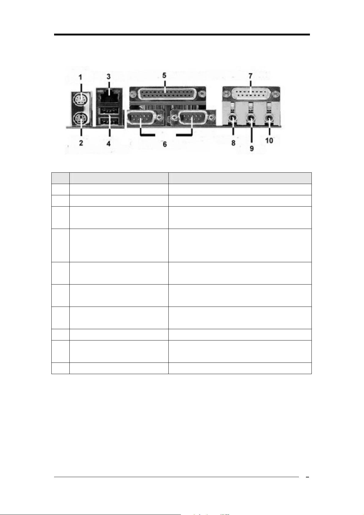
1-4 Rear Panel I/O ports Layout
No. Name Function
1 Green PS/2 mouse port The PS/2 mouse can be hooked up here
2 Purple PS/2 keyboard port The PS/2 keyboard can be hooked up here
Introduction
3 LAN (RJ-45) port
The Twisted-Pair Wire can be hooked up here to
form the so-called Local Area Network (LAN)
The USB 2.0 devices, such as the digital cameras,
4 USB 2.0
camcorders, portable hard disc drive, MP3 player,
etc. can all be hooked up here
The parallel printer, scanner or other devices can
5 Female Parallel Printer port
be hooked up here
The devices such as the modem, old-fashioned
6 Male Serial port (COM1, COM2)
mouse, etc. can be hooked up here
The joystick, game pad or MIDI devices can be
7 GAME/MIDI port
hooked up here
8 Lime Line out port The headphone or speaker can be hooked up here
The tape, CD, DVD player or other audio sources
9 Light blue Line In port
can be hooked up here
10 Pink Microphone port The microphone can be hooked up here
5


Hardware Installation
Chapter 2 Hardware Installation
2-1 PC D.I.Y. Assembly Instructions
1. Installing FDD and IDE devices:
Aligned the red colored edge of the cable with the pin 1 of the drive connector on the
motherboard and gently attached it. Attach the other end of the cable by aligning the colored
edge to the pin 1 of the device connector. Make sure that all drives are securely fastened.
2. Installing a CPU:
Locate a noticeable notch in the CPU’s corner. This marking indicate Pin 1 of the CPU.
Gently insert the CPU with Pin 1 at the same corner of the socket that contains the end of
the lever.
3. Installing System Memory:
Push module downward until side clips are properly secure to the module.
4. Mounting a Motherboard into a Chassis:
Use standoffs and screws to securely mount the motherboard and make sure that all the
mounting holes are properly screwed.
7
Hardware Installation
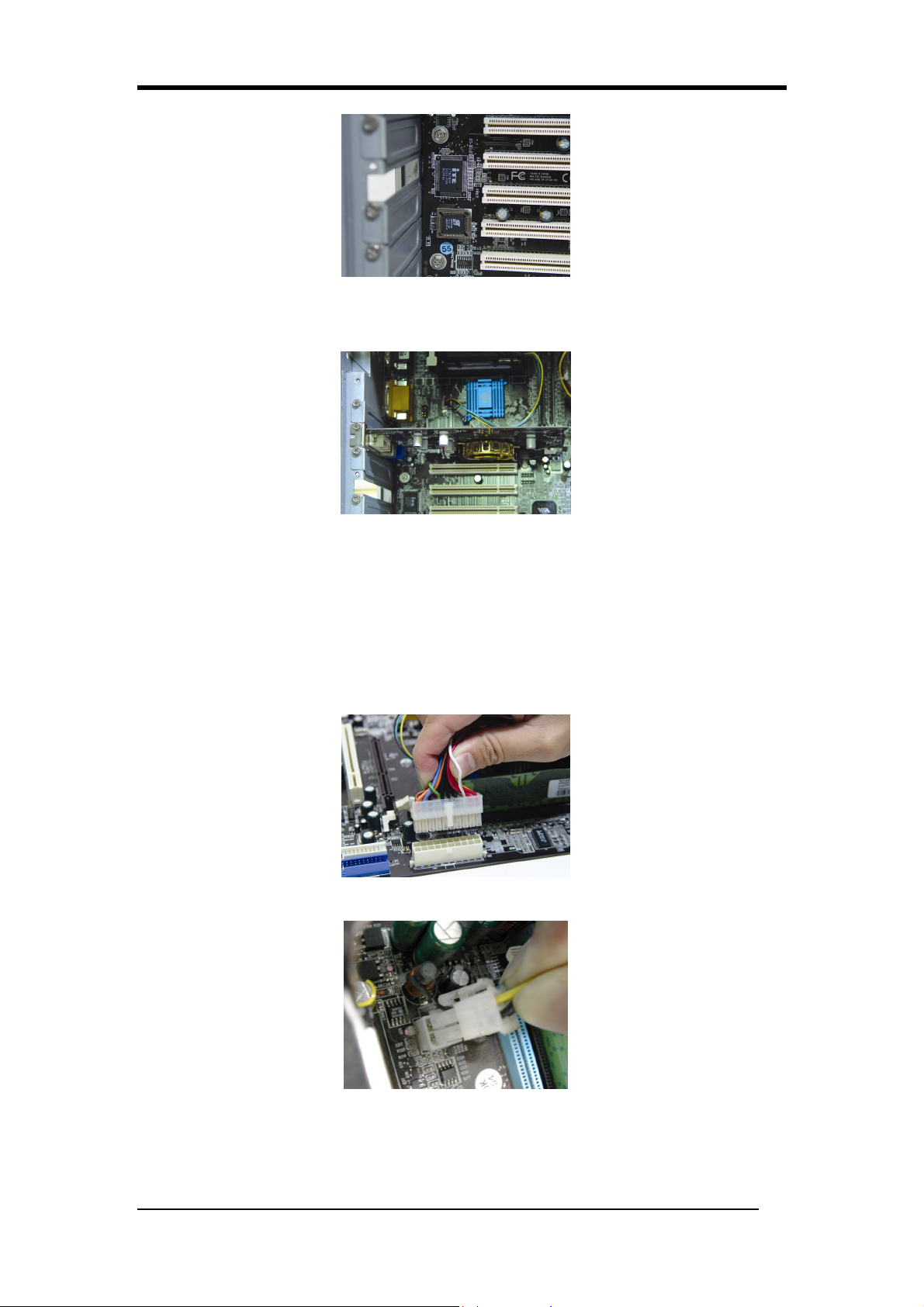
5. Adding an expansion card:
Gently fasten the card to the proper slot.
6. Connecting I/O ports and device connectors:
Simply plug the cable into the respective device port or connector as shown in the manual or
silkscreen printed on the motherboard.
7. Connecting the Power Supply Cables:
Plug in the ATX power cable to the motherboard’s power connector and make sure the cable
is connected.
8
Hardware Installation
The power supply connector is the last connection to be made while installing
please make sure it is not
2-2 Connector and Jumper Settings
Connectors are used to link the system board with other parts of the system, including
power supply, keyboard, and the various controllers on the front panel of the system case.
a motherboard. Before connecting the power supply,
connected to the power source.
All cables come with a security-proof.
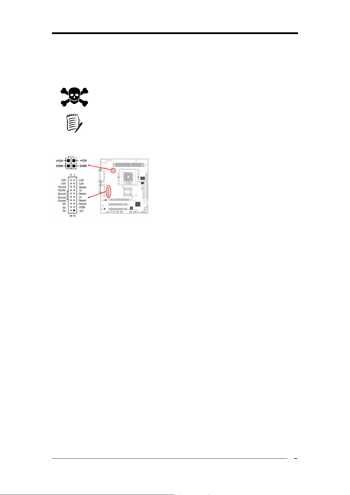
1. PW 1 / 3 (ATX Power Supply Connector):
The power cord leading from the system’s power
supply to the external power source must be the
very last part connected when assembling a system.
The ATX power supply provides a single 20-pin
connector interface, which incorporates standard
+/-5V, +/-12V, optional 3.3V and Soft-power
signals. The Soft power signal, a 5V trickle supply
is continuously supplied when AC power is available. When the system is in Soft-Off mode,
this trickle supply maintains the system in its minimum power state.
The ATX 12V power supply has a new +12V (4-pin) and +5V / 3.3V (6-pin) auxiliary power
connector to enable the delivery of more +12 VDC and + 5/ 3.3V VDC current to the
motherboard.
Power-On By Modem:
While in Soft-Off state, if an external modem ring-up signal is detected, the system will be
activated and therefore can be remotely accessed. You may enable this function in BIOS's
Power Management Setup menu. (See section 3. 6)
Blinking LED in Suspend Mode:
While in Suspend mode, the LED light on the front panel of your computer will flash.
Suspend mode is entered by pressing the Green Override Power Button on your ATX case,
or by enabling the Power Management and Suspend Mode options in BIOS's Power
Management menu. (See section 3.6)
Poly-fuse Over Current Protection:
The poly-fuse protects the system from dangerous voltages that the system might be
exposed to via keyboards or USB connectors. In case of such an exposure, the poly-fuse will
immediately be disconnected from the circuit just like a normal fuse. After being
disconnected for a certain period of time, the poly-fuse will return to its normal state and the
keyboard or USB connector can function properly again. Unlike conventional fuses, the
9

Hardware Installation
poly-fuse will not need to be replaced, relieving users from such inconveniences.
2. Internal connectors
FD1: Floppy Disk Drive Connector (34-1 pin)
To install the FDD, please connect one end of the FDD
signal cable to the connector and the other end to the rear of
the FDD.
IDE1 & IDE2: IDE Connectors (40-1 pin)
This motherboard comes with 2 IDE (Integrated Device
Electronics) connectors, which can connect up to 4 PATA
hard disk drives via the Ultra DMA 133/100/66 signal
cables. If the user attempts to install more than 2 HDDs, he
must configure the master/slave mechanism by setting the
corresponding jumpers on the HDDs. For more details,
please refer to the related information that usually lies on the surface of the HDDs.
SATA1 & SATA2: Serial ATA Connectors (7-pin)
These connectors are used to connect the Serial ATA
Hard Disk Drive(s) via the Serial ATA signal cable. Once
the SATA HDD(s) is(are) installed, remember to connect
the SATA power cable to the rear of it or them and the
power plug of the power supply unit.
CN2: Internal Audio Connector (4-pin CD-IN)
Use the audio cable enclosed with your CD-ROM disk
drive to connect the CD-ROM to your motherboard. This
will enable your CD-ROM’s audio function.
CN23/CN23A: USB Port Connectors (10-1 pin)
These USB connectors comply with USB 2.0
specification that supports up to 480 Mbps transfer
rate. The USB/GAME module(s) can be hooked up
here via the USB/GAME cable(s).
10

CN24: (Front Audio Connector 10-1 pin)
This connector gives you option of a front-panel
audio-jack cable ext. to be plugged into a special
custom-designed system case. Simply remove the
two jumper caps at pins [5-6] and [9-10] then plug it
into the (optional) cable ext. connector. Pins [5-6] and
[9-10] are shorted (default) to enable the back-panel
audio function.
CN26/CN26A: IEEE 1394a port connectors (10-1 pin WAFER1394)
(Optional)
The IEEE 1394 module(s) can be hooked up here via
the IEEE 1394 module cable(s).
Hardware Installation
FAN 1/2/3: CPU, System and Case Fan connectors (3-pin)
These connectors connect the cooling fans via the fan
cables.
JP1: CMOS Clear Jumper
There is a CMOS RAM on board that has a power
supply from external battery to keep the data and
system configuration. To clear the contents of the
CMOS, please follow the steps below.
1. Disconnect the system power supply from the
power source.
2. Set the jumper cap at location [2-3] for <5 seconds>, and then set it back to the default
position.
3. Connect the system's power and then start the system.
4. Enter BIOS's CMOS Setup Utility and choose Load Optimized Defaults.
5. Type [Y] and then press [Enter] to continue.
6. Set the system configuration in the Standard CMOS Setup men
u.
11

Hardware Installation
JP6: Enable/Disable USB 0/1 Device Wake-Up Jumper:
An USB keyboard hot key or an USB mouse-click
can activate this board. To use this function, select a
hot key of your choice at the USB Resume from S3
option under Wake Up Events in the BIOS's Power
On Management screen. You must also set this
jumper's cap to pins 2-3 to use this function.
3. CN1A: Front Panel Connector (18-1 pin)
PWR-SW (Over-ride Power Button Connector):
The power button on the ATX chassis can be
used as a normal power switch as well as a
device to activate the Advanced Power
Management Suspend mode. This is a
power-saving mode used for saving electricity
when the computer is idle for long periods of
time. The Soft-OFF by PWR-BTTN function in BIOS's Power Management Setup menu
must be set to [Delay 4 Sec.] to activate this function.
When the Soft-OFF by PWR-BTTN function is enabled, pressing the power button
rapidly will switch the system to Suspend mode. Any occurrence of external activities
such as pressing any keys on the keyboard or moving the mouse will bring the system
back to Full-On. Pushing the button while in Full-On mode for more than [4 seconds]
will switch the system completely off. See Over-ride Power Button Operation diagram.
P-LED (Power LED Connector):
The power indicator LED shows the system's power status. It is important to pay
attention to the correct cable and pin orientation (i.e. Be careful not to reverse the order of
these two connectors.)
G-BTN (Green Button Switch):
Some ATX cases provide a Green button switch, which is used to put the system in
Suspend mode. While in Suspend mode, the power supply to the system is reduced to a
trickle, the CPU clock is stopped, and the CPU core is in its minimum power state. The
system is activated whenever the keyboard or mouse is touched. The system will resume
in various ways as defined by Power Management Setup screen in BIOS.
RESET (System Reset Switch Connector):
This connector should be connected to the reset switch on the front panel of the system
case. The reset switch allows you to restart the system without turning the power off.
SPEAKER (Speaker Connector):
This 4-pin connector connects to the case-mounted speakers.
12

Hardware Installation
HD-LED (IDE - Activity LED Connector):
The IDE- activity LED lights up whenever the system reads/writes to the IDE devices.
Front Audio Connector (10-1 pin CN24 Front Audio)
This connector give you the option of a front panel audio jack cable ext. to be plug into a
special custom designed system case. Simply remove the two jumper caps at pin [5-6]
and [9-10] then plug it into the (optional) cable ext. connector. Pin [5-6] and [9-10] are
shorted (default) to enable the back panel audio function.
ATX Power Connectors (20-pin ATXPWR & 4-pin ATX 12V)
The plugs of the ATX power supply go here.
Suggestion: Please use the power supply which can support over 350W.
13


Phoenix-Award BIOS CMOS Setup Utility
Chapter 3 Phoenix-Award BIOS CMOS Setup Utility
3-1 Entering Phoenix-Award BIOS CMOS Setup Utility
The Phoenix-Award BIOS CMOS Setup Utility can be entered by pressing {Delete} during
the booting process; accurately speaking, it is during the POST ( Power-On Self Test), one
of major tasks performed by the BIOS when the system is turned on to make certain every
hardware of the system is present and works properly.
3-2 Standard CMOS Features
Date (mm:dd:yy)
Allows users to set the system date. Once set up, the system date will be based on this.
Time (hh:mm:ss)
Allows users to set the system time. Once set up, the system time will be based on this
.
IDE Channel 0~3 Master/Slave
Each of these items shows the name of the IDE devices currently connected to the
motherboard. Select the item desired by using arrow keys then press {Enter} to enter the
sub-menu.
IDE HDD Auto-Detection
The item allows BIOS to auto-detect the IDE devices currently connected to the
motherboard and to show the related information, including Capacity, Cylinder, Head,
Precomp, Landing Zone as well as Sector.
IDE Channel 0~3 Master/Slave
These items allow users to set the status of the IDE devices. [Auto] is recommended.
Available options: [None], [Auto] and [Manual].
Drive A/B
Allows users to choose the type of the floppy disk drive currently used. Available options:
None, 360K, 5.25 in., 1.2M, 5.25in., 720K, 3.5in., 1.44M, 3.5in., 2.88M, 3.5in.
.
Video
Allows users to choose the specification of the monitor currently connected to the
motherboar
d.
Halt On
The item allows users to determine under what condition the system should halt during the
boot process.
If All Errors is selected, the booting process will halt when the system detects any errors on
15

Phoenix-Award BIOS CMOS Setup Utility
hardware during the POST.
If No Errors is selected, the boot process will not halt even though the system detects an
error on hardware during the POST.
If All, But Keyboard is selected, the booting process will halt when the system detects any
errors on hardware except for the keyboard.
If All, But Diskette is selected, the booting process will halt when the system detects any
errors on hardware except for the hard disk drive.
If All, But Disk/Key is selected, the booting process will halt when the system detects any
errors on hardware except for the hard disk drive & keyboard.
3-3 Advanced BIOS Features
Hard Disk Boot Priority
One of the major tasks for the BIOS is to help the CPU load the operating system from the
hard disk drive into the system memory. This feature allows users to set the sequence by
which the BIOS will search for an operating system. Set the hard disk drive that contains the
operating system as the first place for the fastest booting process.
Virus Warning
This feature provides the fundamental anti-virus protection by monitoring writes to the boot
sector and partition table. If enabled, the BIOS will halt the system and flash the warning
message whenever it detects an attempt to write to the boot sector or partition table.
CPU Internal/External Cache
This feature controls the functionality of the CPU’s internal & external cache. If enabled,
the CPU’s internal & external cache will be allowed to work. The CPU performance thus
will largely increase.
CPU L2 Cache ECC Checking
This BIOS feature enables or disables the L2 (Level 2 or Secondary) cache's ECC (Error
Checking and Correction) function, if available.
Enabling this feature is recommended because it will detect and correct single-bit errors in
data stored in the L2 cache. As most data reads are satisfied by the L2 cache, the L2 cache's
ECC function should catch and correct almost all single-bit errors in the memory subsystem.
It will also detect double-bit errors although it cannot correct them. But this isn't such a big
deal since double-bit errors are extremely rare. For all practical purposes, the ECC check
should be able to catch virtually all data errors. This is especially useful at overclocked
speeds when errors are most likely to creep in.
So, for most intents and purposes, I recommend that you enable this feature for greater
system stability and reliability.
Please note that the presence of this feature in the BIOS does not necessarily mean that your
16

Phoenix-Award BIOS CMOS Setup Utility
processor's L2 cache actually supports ECC checking. Many processors do not ship with
ECC-capable L2 cache. In such cases, you can still enable this feature in the BIOS but it
will have no effect.
Quick Power On Self Test
This feature allows you to reduce the time it takes to boot up the system. If enabled, the
BIOS will shorten the booting process by skipping certain some tests and shorten others. It
is recommended that you disable this feature when you boot up the system for the first time
or whenever you install a new piece of hardware. Doing this will allow the BIOS to execute
the complete diagnostic tests to detect the potential problems with the hardware.
First Boot Device
This feature allows users to determine from which device the BIOS will attempt to load the
operating system first. If users want to install the operating system such as Windows XP,
they will need to set the First Boot Device as the CD-ROM to install the operating system
into the Hard Disk Drive (HDD).
Second Boot Device
This feature allows users to determine the Second Boot Device from which the BIOS will
attempt to load the operating system.
Third Boot Device
This feature allows users to determine the Third Boot Device from which the BIOS will
attempt to load the operating system.
Boot Other Device
This feature allows users to determine whether the BIOS will attempt to load the operating
system from the Second Boot Device or the Third Boot Device if it fails to load it from the
First Boot Device.
Swap Floppy Drive
This BIOS feature is used to logically swap the mapping of drives A: and B:. Therefore, it is
only useful if you have two floppy drives.
Normally, the sequence by which you connect the floppy drives to the cable determines
which is drive A: and which is drive B:. If you attach the floppy drives the wrong way and
obtain a drive mapping that is not to your satisfaction, the usual way of correcting this is to
physically swap the floppy cable connectors.
This feature allows you to swap the logical arrangement of the floppy drives without the
need to open up the case and physically swap the connectors.
When this BIOS feature is enabled, the floppy drive that originally was mapped to drive A:
will be remapped to drive B: and vice versa for the drive that was originally
set as drive B:.
17

Phoenix-Award BIOS CMOS Setup Utility
When this BIOS feature is disabled, the floppy drive mapping will remain as that set by the
drive connector arrangement.
Although this appears to be nothing more than a feature of convenience, it can be quite
important if you are using two floppy drives of different form factors (3.5" and 5.25") and
you need to boot from the second drive. Because the BIOS can only boot from drive A:, you
will have to physically swap the drive connections or use BIOS this feature to do it
logically.
If your floppy drive mapping is correct or if you only have a single floppy drive, there is no
need to enable this feature. Leave it at the default setting of disabled.
Boot Up Floppy Seek
If enabled, the BIOS will attempt to detect and initialize the floppy disk drive (FDD) during
the booting process. It will show an error message on the screen when the FDD is not
detected. Nevertheless, the users still can continue the booting process. Enabling this feature
is actually pointless and takes more time to boot up the system. It is recommended that the
users disable it.
Boot Up NumLock Status
There are two input modes for the numeric keypad—numeric & cursor control mode. This
feature allows you to select the mode the keypad will adopt. On represents the numeric
mode and Off, cursor control mode.
Typematic Rate Setting
The feature allows you to control the keystroke repeat feature.
If enabled, you can manually adjust the two following:
Typematic Rate
Typematic Rate Delay
If disabled, the foregoing features will be disabled and greened out. The keyboard
controller will then use the default Typematic Rate & Typematic Rate Delay.
Typematic Rate (Chars/Sec)
You can use this feature only when the Typematic Rate Setting is enabled. The feature
allows users to determine at what rate the keyboard will repeat the keystroke when you
press it continuously. The higher the typematic rate is, the faster the keyboard will repeat the
keystroke.
Typematic Rate Delay (Msec)
This BIOS setting will only work if the Typematic Rate Setting feature has been enabled.
This feature determines how long, in milliseconds (thousandths of a second), the keyboard
controller will wait before it starts repeating the keystroke that you have pressed
continuously. The longer the delay, the longer the keyboard controller will wait before it
18

Phoenix-Award BIOS CMOS Setup Utility
starts repeating the keystroke.
Generally, using a short delay is useful for people who type quickly and don't like to wait
long for a keystroke to be repeated. On the other hand, a long delay is useful for users who
tend to press the keys longer while typing. This prevents the keyboard controller from
unnecessarily repeating keystrokes with such users.
Security Option
This BIOS feature controls the application of the BIOS' password protection. It will only
work once you have created a password through the Password Setting option in the main
BIOS screen.
Selecting the System option will force the BIOS to ask for the password every time the
system boots up.
If you choose Setup, then the password is only required for access to the BIOS. This option
is useful for system administrators or computer resellers who need to keep novice users
from messing around with the BIOS
APIC Mode
By enabling this option, “MPS version control for OS” can be configured.
MPS Version Control For OS
The 1.1 version is the older version that supports 8 more IRQs in the Windows NT
environment. Choose the new 1.4 version for Windows 2000 and Windows XP.
OS Select for Dream >64MB
If your system’s DRAM is larger than 64MB and you are running OS/2, select OS/2 as the
item value. Otherwise, set the item value to Non-OS/2 for all other operating systems.
HDD S.M.A.R.T. Capability
S.M.A.R.T. or Self-Monitoring, Analysis, and Reporting Technology enables a drive’s
internal status to be monitored through diagnostic commands. Both your hard drive must
support this capability and this function must be enabled in order to take advantage of this
function. See your hard drive literature for more information.
Video BIOS Shadow
These fields allow you enable/disable the shadow feature for the Video BIOS and the
appropriate memory segment.
Small Logo (EPA) Show
This function allows you to show or hide the small Logo EPA. If Enabled, the EPA Logo
shows up on the screen when you boot up the system.
19

Phoenix-Award BIOS CMOS Setup Utility
Show POST CODE
Enabling this function can show POST error code on the screen before proceeding to
system’s operating system.
3-4 Advanced Chipset Features
DRAM Configuration
Press Enter to enter the submenu.
Current FSB Frequency
This feature shows the current FSB frequency.
Current DRAM Frequency
This feature shows the current DRAM frequency.
Max Memclock (Mhz)
This feature allows you to select the memory clock. When it set to “Auto”, the system will
automatically detect the memory clock.
CAS# latency (Tcl)
The feature controls the latency between the SDRAM read command and the time the data
really becomes available. In other words, the lower the CAS Latency Time is, the faster the
memory reads or writes can occur. Note that not every memory module is capable of dealing
with the lower CAS Latency Time and may lose date for this. Therefore, you shall increase
it as the system becomes unstable.
LDT & PCI Bus Control
Upstream LDT Bus Width
This function determines the upstream width of the LDT bus of which connects CPU and
MK8T890 chip. Please leave the default setting [16 bit] for a stable system operation.
Downstream LDT Bus Width
This function determines the downstream width of the LDT bus of which connects CPU and
MK8T890 chip. Please leave the default setting [16 bit] for a stable system operation.
PCI1/PCI2 Master 0 WS Write
When enabled, allows a zero-wait-state-cycle delay when the PCI master drive writes data
to DRAM.
PCI1/2 Post Write
Enabling this function will enhance the system efficiency.
PCI Delay Transaction
Enable it to abort the current PCI master cycle and accept a new PCI master request, it
reaccepts the original PCI master, returns PCI date phase to the original PCI master.
Memory Hole
This feature enables users to determine whether the 15th~16th (1MB) block of memory will
be reserved for the ISA cards or not. If enabled, 1MB of memory will be reserved
20

Phoenix-Award BIOS CMOS Setup Utility
exclusively for the ISA cards. Thus the total amount of memory the operating system uses
will decrease. If disabled, the 15th MB of RAM will not be reserved for the ISA cards and
there will be a full range of memory available to the operating system. Since the ISA cards
are a thing of the past, it is highly recommended that you disable this feature.
VLink Mode Selection
Enable this setting to utilize the 16X mode (twice as fast as 8X) offered by advanced PCIE
cards. Your PCIE card must support 16X mode in order to take advantage of the faster
speed.
Init Display First
This BIOS feature allows users to select whether to boot the system using the PCIE
graphics card or the PCI graphics card. This is particularly important if you have PCIE and
PCI graphics cards but only one monitor.
If you are only using a single graphics card, then the BIOS will detect it as such and boot it
up, irrespective of what you set the feature to. However, there may be a slight reduction in
the time taken to detect and initialize the card if you select the proper setting for this BIOS
feature. For example, if you only use a PCIE graphics card, then setting Init Display First to
PCIE may speed up your system's booting-up process.
Therefore, if you are only using a single graphics card, it is recommended that you set the
Init Display First feature to the proper setting for your system (PCIE for a single PCIE card
and PCI for a single PCI card).
But if you are using multiple graphics cards, it is up to you which card you want to use as
your primary display card. It is recommended that you select the fastest graphics card as the
primary display card.
System BIOS Cacheable
This feature enables users to determine whether the BIOS in the flash ROM will be cached
by the processor’s L2 cache or not. If enabled, the access to the BIOS will speed up.
Nevertheless, the modern operating systems, such as Microsoft Windows XP, are designed
to communicate with the hardware via the drivers instead of the BIOS. Thus it will be a
waste for the L2 cache to store the BIOS. In addition, enabling this feature often results in
the system crash. Disabled is recommended.
Flash BIOS Protection
The Flash BIOS Protection feature is a software toggle that controls write access to the
BIOS. When it is enabled, the BIOS code is write-protected and cannot be changed. This
protects it from any attempt to modify it, including BIOS updates and virus attacks.
Therefore, if you intend to update the BIOS, you'll need to disable this feature first.
It is highly recommended that you enable this feature at all times. You should only disable it
21

Phoenix-Award BIOS CMOS Setup Utility
when you intend to update the BIOS. After updating the BIOS, you should immediately
re-enable it to protect the BIOS against viruses.
3-5 Integrated Peripherals
VIA OnChip IDE Device
OnChip SATA
Allows you to enable or disable the SATA device(s).
SATA Mode
Allows you to select the SATA mode.
IDE DMA transfer access
Allows you to set IDE transfer mode to Direct Memory Access (DMA) mode.
OnChip IDE Channel0
Allows you to enable or disable the IDE channel0.
OnChip IDE Channel1
Allows you to enable or disable the IDE channel1.
IDE Prefetch Mode
The onboard IDE drive interfaces support Prefetching for faster drive accesses. Set to
Disabled if this primary or secondary.
Primary Master PIO
This feature allows you to set the PIO (Programmable Input/Output) mode for the IDE
Primary Master drive attached to the IDE1 connector. Auto is recommended.
Primary Slave PIO
This feature allows you to set the PIO (Programmable Input/Output) mode for the IDE
Primary Slave drive attached to the IDE1 connector. Auto is recommended.
Secondary Master PIO
This feature allows users to set the PIO (Programmable Input/Output) mode for the IDE
Secondary Master drive attached to the IDE2 connector. Auto is recommended.
Secondary Slave PIO
This feature allows users to set the PIO (Programmable Input/Output) mode for the IDE
Secondary slave drive attached to the IDE2 connector. Auto is recommended
Primary Master UDMA
This feature allows users to set the Ultra Direct Memory Access (UDMA) mode for the IDE
Primary Master drive attached to the IDE1 connector. Auto is recommended.
Primary Slave UDMA
This feature allows users to set the Ultra Direct Memory Access (UDMA) mode for the IDE
Primary Slave drive attached to the IDE1 connector. Auto is recommended.
Secondary Master UDMA
This feature allows users to set the Ultra Direct Memory Access (UDMA) mode for the IDE
Secondary Master drive attached to the IDE2 connector. Auto is recommended.
22

Phoenix-Award BIOS CMOS Setup Utility
Secondary Slave UDMA
This feature allows users to set the Ultra Direct Memory Access (UDMA) mode for the IDE
Secondary Slave drive attached to the IDE2 connector. Auto is recommended.
IDE HDD Block Mode
This feature enables users to speed up the hard disk access by transferring the data in the
block mode. Enabled is recommended.
VIA OnChip PCI Device
VIA-3058 AC97 Audio
This feature allows you to set the status of VIA-3058 AC97 Audio.
VIA-3043 OnChip LAN
This feature allows you to enable or disable the VIA-3043 OnChip LAN.
Onboard Lan Boot ROM
This feature allows you to enable or disable the Onboard Lan Boot ROM.
OnChip USB Controller
This feature allows you to enable or disable the OnChip USB Controller.
OnChip EHCI Controller
This feature allows you to enable or disable the OnChip EHCI Controller.
USB Emulation
Option Description
OFF Do not support any USB device on DOS
KB/MS Support USB legacy keyboard & mouse. No support USB storage
ON Support USB legacy keyboard, mouse & storage
USB Keyboard Support
This feature allows users to determine whether the USB keyboard is supported by the BIOS
or the operating system. If users’operating system supports the USB keyboard, such as
Windows XP, they shall disable this feature. If not, this feature shall be enabled. But this
only provides the basic functions for the USB keyboard.
USB Mouse Support
Select Enabled if your system has a USB mouse installed on the system board. If your
system has no USB mouse, select Disabled in this field.
SuperIO Device
Onboard FDC Controller
Allows you to enable or disable the Onboard FDC Controller.
Onboard Serial Port 1
This feature allows users to select the I/O address and IRQ for the first serial port. Auto is
recommended. Nevertheless, you can manually choose another I/O port or IRQ if a certain
I/O port or IRQ is needed. Disabling this feature can free up the I/O port and IRQ resources
23

Phoenix-Award BIOS CMOS Setup Utility
for other devices
Onboard Serial Port 2
This feature allows users to select the I/O address and IRQ for the second serial port. Auto
is recommended. Nevertheless, you can manually choose another I/O port or IRQ if a
certain I/O port or IRQ is needed. Disabling this feature can free up the I/O port and IRQ
resources for other devices.
Onboard Parallel Port
This feature allows users to select the I/O address and IRQ for the onboard parallel port.
Auto is recommended. Nevertheless, you can manually choose another I/O port or IRQ if a
certain I/O port or IRQ is needed. Disabling this feature can free up the I/O port and IRQ
resources for other devices.
Parallel Port Mode
This feature allows users to select the transfer protocol for the parallel port.
Normal (SPP) stands for the Standard Parallel Port, which is the original transfer
protocol for the parallel port. Therefore, it works fine with all the parallel port devices.
ECP (Extended Capabilities Port) is a transfer mode that uses the DMA protocol to
reach data transfer rate of up to 2MB/s and provides symmetric bidirectional
.
communication.
EPP (Enhanced Parallel Port) is also referred to as IEEE 1284. It uses the existing
parallel port signal to reach data transfer rate of up to 2MB/s and provides asymmetric
communication bidirectional communication.
Some parallel port devices designate certain transfer protocol. Please refer to the
documentation that comes with them. If users are not sure what transfer protocol shall be
selected, they can use ECP+EPP so that the BIOS will automatically determine the transfer
mode suitable for the device.
ECP Mode Use DMA
If the ECP or ECP+EPP mode in the above feature is selected, this feature will become
selectable to enable users to choose the DMA channel 1 or 3.
Game Port Address
This feature allows users to select the I/O address for the Game port.
Midi port Address
This feature allows users to select the I/O address for the Midi port.
Midi Port IRQ
This feature allows users to select the IRQ for the Midi port.
3-6 Power Management Setup
ACPI Suspend Type
This feature allows users to select the ACPI suspend type. You can select S1(POS) for
Power On Suspend under ACPI mode, or S3 (STR) for Suspending To RAM.
24

Phoenix-Award BIOS CMOS Setup Utility
Power Management Option
To select the type (or degree) of power saving for Doze, Standby, and Suspend modes.
HDD Power Down
Allows automatic power down of IDE drives after a specified period of inactivity, but 15
minutes is a suggested minimum, to avoid undue wear and tear on the drive.
Suspend Mode
Allows the system to go to Suspend State after a period of inactivity. If the system runs in
Standby mode and the Suspend timer expires, all devices regulated by power management
will shut off and the CPU speed will be 0 MHz.
Video off option
This setting allows you to select the power-saving modes during which the monitor goes
blank.
Blank – BIOS will only blank the monitor’s screen. The electricity saved in this mode
is negligible and this function is only used as a screen saver to prevent screen damage
while the screen is on but not in use.
V/H SYNC=Blank – The system turns off the vertical and horizontal synchronization
ports writes blanks to the VGA buffer and the monitor’s electron gun turns off. This
function serves as both a screen saver and a power saver.
DPMS Supported – Select this option if your video card supports the Display Power
Management Signaling (DPMS) standard (i.e., you have a monitor that supports Green
features). Use software supplied by your video subsystem to set video power
management options.
Video off method
This function serves as both a screen saver and power saver for monitors. See the next
function, Video Off After, for setting the video timer.
MODEM Use IRQ
If your computer has a modem use this function to assign BISO which IRQ is being
occupied by the modem card. When the system in Green mode, the modem requires an IRQ
assignment to wake up the system and perform tasks. This is compliant with APM 1.2
operating systems.
Soft-off by RWRBTN
When set to Delay 4 Sec., this function allows the power button to put the system in
Suspend, a power saving mode. When set to Instant-Off the Soft-Off by PWR-BTN function
is disabled and the computer turns completely off when the power button is pressed.
25

Phoenix-Award BIOS CMOS Setup Utility
Run VGABIOS if S3 Resume
Available options: Auto, Yes, No.
Ac Loss Auto Restart
Available options: [Former-Sts], [On], [Off]. Please leave the default setting [Off] for a
stable system operation.
AMD K8 Cool n Quiet Control
When set to “Auto”, the system will auto control the CPU voltage and frequency depends
the loading of system.
IRQ/Event Activity Detect
PS2KB Wakeup Select
When enabled, a PS2 keyboard can turn on the system.
PS2KB Wakeup From S3/S4/S5
This function allows the keyboard to activate the system from S3/S4/S5 power saving
modes. Available opinions: Ctrl+F1 through Ctrl+F12, Power, Wake and Any Key.
USB Resume from S3
When enabled, the system is able to resume from S3 mode by a USB keyboard hot key or
mouse click.
VGA
VGA function is activated when option On is selected. Available options: On, Off. If your
motherboard doesn’t offer AGP slot, this function wouldn’t work.
LPT & COM
Both LPT and COM ports are activated when LPT/COM is selected. Available options:
None, LPT, COM, LPT/COM.
HDD & FDD
Both HDD and FDD are activated when it is set to On. Available options: On, Off.
PCI Master
This options control the activation of PCI slots. Available options: On, Off.
PowerOn by PME/Onboard LAN
When enabled, the Vidia LAN, which is on Board, will be able to receive a signal and wake
up the system from soft off and suspend mode. You should connect the LAN to the RJ45
port and turn on the resume event in suspend mode.
PowerOn by Ring/WOL
When enabled, a Modem/LAN will be able to receive a signal and activate the system from
soft off and green mode. You should connect the modem to the COM port and signal your
PC to power on.
26

Phoenix-Award BIOS CMOS Setup Utility
RTC Alarm Resume
Enabled allows the user to set the time the system will be turned on from the system
power-off status.
Date (of Month)
This feature allows the user to set the day of the alarm starts when the RTC Alarm Resume
From Soft Off is set to be Enabled.
Resume Time (hh:mm:ss)
If an ATX power supply is installed and when RTC Alarm Resume is Enabled, this feature
allows you to set the time of the alarm starts when the RTC Alarm Resume From Soft Off is
set to be Enabled.
IRQs Activity Monitoring
Primary INTR
If set at On, the Primary interrupt will make the power management wake up the system.
IRQ3~15
After the time period which you set, the system advances from doze mode to suspend mode
in which the CPU clock stops and the screen display is off. At this moment, if the IRQ
activity occurs, the system goes back to full on mode directly.
3-7 PnP/PCI Configurations
PnP OS installed
If all your operating systems support Plug & Play (PnP0, select Yes so that they can take
over the management of device resources. If you are using a non-PnP-aware OS or not all of
the operating systems you are using support PnP, select No to let the BIOS handle it instead.
Some say that it is best to leave this option set to No regardless of whether your OS is
PNP-capable or not. The reason is that when it is set to No, the BISO will attempt to
resolve any resource conflicts. If it is set to Yes, even if a conflict is detected, the BIOS
will ignore it. So, setting it to Yes provide a bit of a safety net, and it will not affect the
ability of the OS to perform PNP on its own.
Reset Configuration Data
ESCD (Extended System Configuration Data) is a feature of the Plug & Play BIOS that
stores the IRQ, DMA, I/O and memory configuration of all the ISA, PCI and PCIE cards in
the system (PnP or otherwise). Normally, you should leave the setting as Disabled. If you
encounter serious problems with the installation of a new PCI card, this setting can help bail
you out. Such a conflict would be serious enough that the OS may not start. If this happens,
you can go into the BIOS and enable this option. Next time the PC boots, the BISO will go
and re-configure the settings for all PnP cards. The BIOS will automatically reset this setting
to DISABLED next time you boot.
27

Phoenix-Award BIOS CMOS Setup Utility
Resources Controlled By
When set to Manual the system BIOS will not refer to the ESCD for IQR & DMA
information. Instead, it will refer to the items in the setup menu for assigning IRQ & DMA.
When set to Auto the system BIOS will refer to the ESCD for all legacy information. ESCD
(Extended System Configuration Data) provides a detailed format of the configuration data
structures stored in flash memory. Each data structure defines the resources used by a device
or a card in the system. This includes legacy and PCI/ISA PnP devices.
PCI/VGA Palette Snoop
This option is only useful if you use an MPEG card and an add-on card that make use of the
graphics card’s Feature Connector. It corrects incorrect color reproduction by “snooping”
into the graphics card’s framebuffer memory and modifying (synchronizing) the information
delivered from the graphics card’s Feature Connector to the MPEG or add-on card. It will
also solve the problem of display inversion to a black screen after using the MPEG card.
Assign IRQ for VGA
Many high-end graphics accelerator cards now require and IRQ to function properly.
Disabling this feature with such cards will cause improper operation and/or poor
performance. Thus, it’s best to make sure you enable this feature if you are having problems
with your graphics accelerator card. If your motherboard doesn’t offer AGP slot, this
function wouldn’t work.
Assign IRQ for USB
Assigns and IRQ to the USB controller. It enables or disables IRQ allocation for the USB
(Universal Serial Bus). If you are using PCIE, this should be enabled. If you are not, you
disable this to free up an IRQ.
FDD IRQ Can Be Free
This function allows user to choose if the FDD IRQ can be free up. The default setting is
Yes and this does not allow the IRQ to be free.
Maximum Payload Size
This function can be used to set maximum TLP payload size for the PCI Express devices.
The unit of payload size is byte.
3-8 Frequency/Voltage Control
Auto Detect PCI Clk
This feature allows users to determine whether the BIOS will automatically reduce the EMI
(Electromagnetic Interface) and the power consumption by shutting down the unoccupied or
inactive expansion slots. If enabled, the BIOS will monitor the PCI slots and will turn off
the clock signal to all the unoccupied or inactive PCI slots. If disabled, the BIOS will not do
28

Phoenix-Award BIOS CMOS Setup Utility
the thing mentioned above. It is recommended that users enable this feature to save power
and reduce EMI.
Spread Spectrum
This BIOS feature allows you to reduce the EMI of your motherboard by modulating the
signals it generates so that the spikes are reduced to flatter curves. It achieves this by
varying the frequency slightly so that the signal does not use any particular frequency for
more than a moment.
The BIOS usually offers two levels of modulation - 0.25% or 0.5%. The greater the
modulation, the greater the reduction of EMI is. Therefore, if you need to significantly
reduce your motherboard's EMI, a modulation of 0.5% is recommended.
In most conditions, frequency modulation via this feature should not cause any problems.
However, system stability may be slightly compromised in certain situations.
Spread Spectrum can also cause problems with overclocked systems, especially those that
have been taken to extremes. Even a slight modulation of frequency may cause the
processor or any other overclocked components of the system to fail, leading to very
predictable consequences.
Therefore, it is recommended that you disable this feature if you are overclocking your
system. The risk of crashing your system is not worth the reduction in EMI. Of course, if
EMI reduction is important to you, enable this feature by all means. But you should reduce
the clock speed a little to provide a margin of safety.
Some BIOSes also offer a Smart Clock option. Instead of modulating the frequency of
signals over time, Smart Clock turns off the PCIE, PCI and SDRAM clock signals that are
not in use. Therefore, EMI can be reduced without compromising system stability. As a
bonus, using Smart Clock also helps reduce power consumption. The degree of EMI and
power reduction will depend on the number of empty PCIE, PCI and SDRAM slots. But
generally, Smart Clock won't be able to reduce EMI as effectively as simple frequency
modulation.
With that said, it is recommended that you enable Smart Clock, instead of the 0.25% or 5%
option, if the option is available to you. It allows you to reduce some EMI without any risk
of compromising your computer's stability.
CPU Host/PCIEX/ AGP/PCI
Allows you to set the frequency of CPU, PCI and PCIE. Options: Default, 202/101/67/34
MHz, 206/103/68/34 MHz, 210/105/69/35 MHz and 215/107/71/35 MHz, 220/110/73/36
MHz.
Shutdown By LM90
This item allows you to set the shutdown temperature level for the processor. When the
processor reaches the temperature you set, the system will shutdown. The defaulted option
29

Phoenix-Award BIOS CMOS Setup Utility
is [95℃/203℉]. Available options are [95℃/203℉], [85℃/185℉] and [75℃/167℉].
LM90 Temp
CPU temperature can be detected and shown by the LM90.
3-9 Load Fail-Safe Defaults
If you made changes to the BIOS and your system becomes unstable as a result, you can
change it back to default. However if you made many changes and don't know which one is
causing the problem, your best bet is to choose the option "Load Fail Safe Mode Defaults"
from the BIOS menu. This uses a minimal performance setting, but the system would run in
a stable way. From the dialog box Choose "Y" followed by enter to load Fail-Safe Defaults.
3-10 Load Optimized Defaults
Like the Fail-Safe mode above, this option loads the BIOS default settings, but runs the
system at optimal performance. From the dialog box Choose "Y" followed by enter to load
Optimized Defaults
.
3-11 Set Supervisor Password
Select this option to set the supervisor password. The supervisor password is the higher
level password of the two normally present on the system. On most systems, when the
supervisor password has been set, it must be entered in order to access the BIOS setup
program, or to change the user password.
3-12 Set User Password
Select this option to set the user password. The user password is the lower level password of
the two normally present on the system. The user password usually allows the system to be
booted, but does not allow access to the BIOS setup program. The supervisor password must
be used to enter the BIOS setup program.
Note: On some systems, either the supervisor or user passwords will allow access to the
BIOS setup program. In this case the existence of two passwords may be to allow a single
password to be set up for an administrator, which will work for multiple machines, while the
user password is individual for each machine.
3-13 Save & Exit Setup
Save all configuration changes to CMOS (memory) and exit setup. A confirmation message
will be displayed before proceeding.
3-14 Exit Without Saving
If you don't want to save changes made to the BIOS, choose "N" from the dialog box.
30
Driver Setup
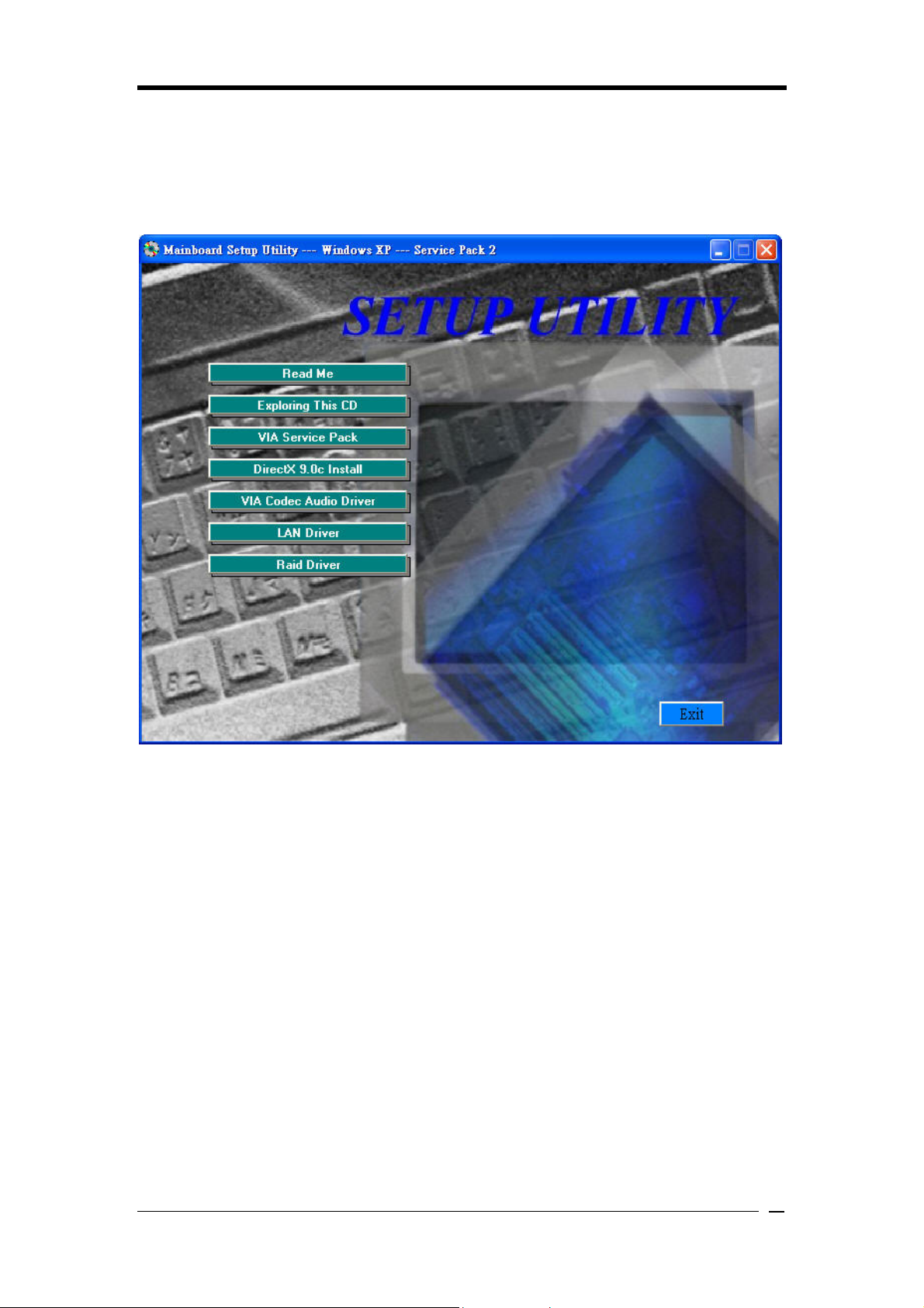
Chapter 4 Driver Setup
Insert the support CD that come with your motherboard into your CD-ROM driver or
double-click the CD drive icon in [My computer] to enter the setup screen.
4-1 VIA Service Pack
1. Click [VIA Service Pack].
2. Click [Next] to start software installation.
3. Click [Yes] to continue.
4. Select either Normal or Quick Installation and click [Next] to continue.
5. Select the driver types and click [Next] to continue.
6. Select [Install VIA PCI IDE Bus Driver] and click [Next] to proceed.
7. Select enable DMA Mode then click [Next].
8. Install AGP driver and click [Next] to continue.
Select [Yes, I want to restart my computer now] or [No, I will restart my computer later]
and then click [Finish] to complete the setup process.
4-2 DirectX 9.0c Install
This section provides information on installed DirectX devices by choosing [DirectX] from
the Setup Driver menu.
31

Driver Setup
1. Please select [I accept the agreement].
2. Please select [Next].
3. Please select [Next].
4. Please select [Finish] to complete.
4-3 VIA Codec Audio Driver
1. Select [Audio driver] to begin the software installation
2. Click [Next]
3. Select Install driver then click [Next].
4. Select [Yes, I want to restart my computer now] or [No, I will restart my computer
later] and then click [Finish] to complete the setup process.
4-4 LAN Driver
1. Click [LAN Driver]
2. Click [Yes] to restart the system.
4-5 Raid Driver
1. Click [VIA Raid Driver].
2. Click [Next] to begin the installation process.
3. Click [I agree] to accept the license agreement, and click [Next] to continue.
4. Select the installation items, and then click [Next] to continue.
5. Click [Next] to continue.
6. Select [Yes, I want to restart my computer now] or [No, I will restart my computer
later] and then click [Finish] to complete the setup process.
32

Appendix
Appendix
For Windows 2000/XP Server SATA setup instruction
After you unpack driver, please copy files & subdirectories under directory
D:\Raid\Via\DriverDisk (assuming your optical drive is D) to the root directory of floppy
diskette (called driver diskette).
Therefore, in root directory of floppy diskette you will see:
(1) Files "txtsetup.oem",
(2) Directory "RAID", “PIDE"and related driver files in each directory.
1. Booting from CD-ROM, when the Windows XP Setup blue screen appear and prompt
user to Press F6 if you need to install third party SCSI or RAID driver, please press F6
key.
2. The setup program will continue, later when the setup program prompts user to specify
additional adapters, please press S Key.
3. Then the setup program will prompt user to insert the driver diskette. Please insert the
driver diskette, then press ENTER to continue.
4. The follow-up window will list out the installation choices, please SCROLL down the
list to select "VIA RAID Combo Driver Diskette" for Windows 2000/XP and press
ENTER to continue.
5. If users want to install other devices, please operate at this time. If all devices have
been successfully installed, please go to next step.
6. Press ENTER to continue Windows 2000/XP setup.
33

Note
NOTE
All rights are reserved for the products and corporate names/logos that appear in this
manual to their original owners.
WE reserve all rights to change this manual. All information is subject to change without
notice.
34

How To Contact CHAINTECH
Please do not hesitate to contact us if you have any problem about our products. Any opinion
will be appreciated.
<Headquarters>
For Asia, Africa, Australia and Pacific
Island:
CHAINTECH COMPUTER CO., LTD
4F.-5, No.16, Jian 8th Rd., Zhonghe City,
Taipei County 235, Taiwan
Tel: +886-2-8226-8188
Fax: +886-2-8226-8199
URL: http://www.chaintech.com.tw
E-mail: sales@chaintech.com.tw
For Australia: (VGA only)
Protac International Computers Australia
Sydney Headquarters:
95 Derby St. Silverwater, NSW 2128
Tel: +61- 2-8748-8888
Fax: +61-2-8748-8801
http://www.protac.com.au
Melbourne:
Unit 7, 2 Sarton Rd, Clayton VIC 3168
Tel: +61-3-9560-7188
Fax: +61-3-9560-7288
For Korea:
CHAINTECH KOREA CO., LTD.
14F, Mi-Won B/D, Yeouido-Dong 43,
Youngdeunpo-Gu, Seoul, Korea
Tel: +82-2-6332-3377
Fax: +82-2-6332-3379
URL: http://www.chaintechkorea.com
E-Mail: sales@chaintechkorea.com
For France, Europe:
AELT COMPUTER
5 rue de Rome 93561 Rosny Sous Bois
Cedex France
Tel: +33-1-4855-5940
Fax: +33-1-4855-5942
URL: http://www.chaintech-france.com
E-mail: infos@chaintech-france.com
RMA:
rma@chaintech-france.com
Technical Support:
support@chaintech-france.com
For America:
CHAINTECH AMERICA CORP.
4427 Enterprise St. Fremont CA 94538, U.S.A.
Tel: +1-510-656-3648
Fax: +1-510-656-2297
URL: http://www.chaintechusa.com
E-mail (Sales): sales@chaintechusa.com
Technical Support:
Tel: +1-510-656-3607
Email:support@chaintechusa.com
For China:
CHAINTECH, SHENZHEN
Room 301, Nanguang Building, No.1004,
Huafu Rd, Futian District,Shenzhen, China
518041
Tel: +86-755-8368-9072
Fax: +86-755-8368-9053
CHAINTECH, BEIJING
Room 3A05, 4 Floor, Unit No. B1, Longrange
World Office Building 2, No.18 Suzhou Street,
Haidian District, Beijing, China 100080
Tel: +86-10-6265-0087
Fax: +86-10-6262-0267
URL: http://www.chaintech.com.cn;
http://www.chaintech.cn
E-MAIL: service@chaintech.com.cn
 Loading...