


CHAINTECH
9PJL
Intel® Socket 478
Intel® 865PE + ICH5
ATX Motherboard
User’s Guide
Version 1.0

Declaration of Conformity
According to 47 CFR, Parts 2 and 15 of the FCC Rules
The following designated product:
EQUIPMENT: MAINBOARD
MODEL NO.: CT-9PJL
is a Class B digital device that complies with 47 CFR Parts 2 and 15 of the FCC
Rules. Operation is subject to the following two conditions:
1. This device may not cause harmful interference.
2. This device must accept any interference received, including interference that
may cause undesired operation.
This declaration is given to the manufacturer:
CHAINTECH-EXCEL COMPUTER INC.
4427 Enterprise St. Fremont, CA 94538, U.S.A.
http://www.chaintechusa.com
Chaintech President: Simon Ho
Signature:

Federal Communications Commission Statement
This device complies with FCC Rules Part 15. Operation is subject to the following two conditions:
* This device may not cause harmful interference.
* This device must accept any interference received, including interference that may cause undesired operation.
This equipment has been tested and found to comply with the limits for a Class B digital device, pursuant to
Part 15 of the FCC Rules. These limits are designed to provide reasonable protection against harmful interference
in a residential installation. This equipment generates, uses, and can radiate radio frequency energy. If this
equipment is not installed and used in accordance with the manufacturer's instructions, it may cause harmful
interference to radio communications. However, there is no guarantee that interference will not occur in a
particular installation. If this equipment does cause harmful interference to radio or television reception, which can
be determined by turning the equipment off and on, the user is encouraged to try to correct the interference by one
or more of the following measures:
* Reorient or relocate the receiving antenna.
* Increase the separation between the equipment and receiver.
* Connect the equipment to an outlet on a circuit different from that to which the receiver is connected.
* Consult the dealer or an experienced radio/TV technician for help.
The use of shielded cables for connection of the monitor to the graphics card is required to assure
compliance with FCC regulations. Changes or modifications to this unit not expressly approved by the party
responsible for compliance could void the user's authority to operate this equipment.
Canadian Department of Communications Statement
This digital apparatus does not exceed the Class B limits for audio noise emissions from digital apparatuses
set out in the Radio Interference Regulations of the Canadian Department of Communications.
Manufacturer's Disclaimer Statement
The information in this document is subject to change without notice and does not represent a commitment
on the part of the vendor. No warranty or representation, either expressed or implied, is made with respect to the
quality, accuracy or fitness for any particular purpose of this document. The manufacturer reserves the right to
make changes to the content of this document and/or the products associated with it at any time without obligation
to notify any person or organization of such changes. In no event will the manufacturer be liable for direct, indirect,
special, incidental or consequential damages arising out of the use or inability to use this product or documentation,
even if advised of the possibility of such damages. This document contains materials protected by copyright. All
rights are reserved. No part of this manual may be reproduced or transmitted in any form, by any means or for any
purpose without expressed written consent of it's authors. Product names appearing in this document are mentioned
for identification purposes only. All trademarks, product names or brand names appearing in this document are
registered property of their respective owners.
Printed in Taiwan.
Apr 2003
100%
OST-CONSUMER
RECYCLED PAPER

TABLE OF CONTENTS
Chapter 1
Introduction............................................................... 1
1-1 Product Specifications .....................................................................................1
1-2 Package Contents............................................................................................. 3
1-3 CHAINTECH’s Special Features:...................................................................4
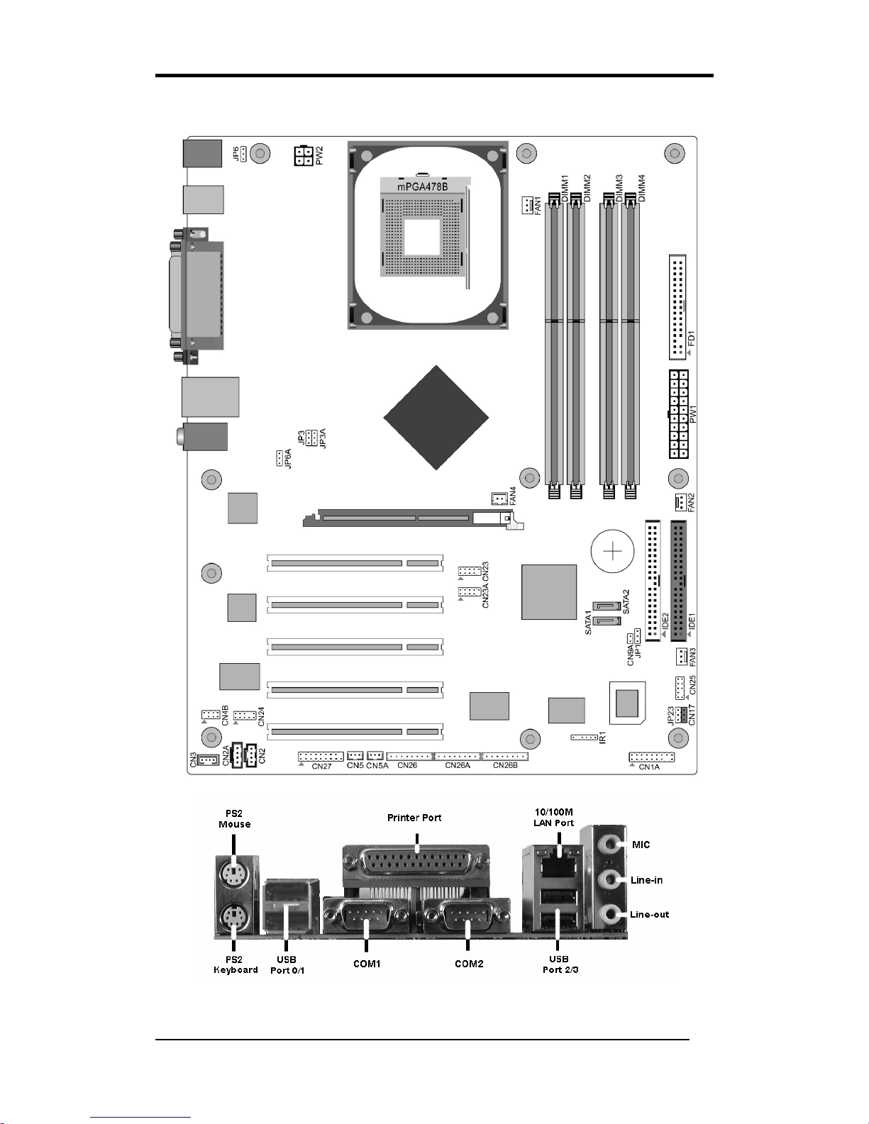
1-4 9PJL Motherboard Diagram ............................................................................5
1-5 9PJL Motherboard Layout...............................................................................6
Chapter 2
Hardware Setup........................................................ 7
2-1 Installing a CPU Processor for Socket 478 .....................................................7
2-2 Setting your CPU’s Parameters .......................................................................8
2-3 Main Memory Configuration......................................................................... 11
2-4 Connector and Jumper Reference Chart........................................................15
2-5 Connector and Jumper Settings .....................................................................16
2-6 Serial ATA and Parallel ATA .........................................................................29
2-7 CBOX™ 2 and 6GFKIT Setup......................................................................31
Chapter 3
BIOS Setup Program.............................................. 32
3-1 Standard CMOS Setup...................................................................................33
3-2 Advanced BIOS Features ..............................................................................34
3-3 Advanced Chipset Features ........................................................................... 37
3-4 Integrated Peripherals ....................................................................................39
3-5 Power Management Setup.............................................................................43
3-6 PNP/PCI Configurations................................................................................46
3-7 PC Health Status............................................................................................47
3-8 Frequency/Voltage Control............................................................................48
3-9 Load Fail-Safe Defaults.................................................................................49
3-10 Load Optimized Defaults.............................................................................49
3-11 Supervisor Password & User Password Setting
...................................................49
3-12 Save and Exit Setup.....................................................................................49
3-13 Exit Without Saving ....................................................................................50
Chapter 4
DRIVER Setup........................................................ 51
4-1 Intel® IDE Bus Mastering Drivers Setup......................................................51
4-2 C-Media Sound Driver Setup ........................................................................ 53
4-3 Intel® LAN Driver Setup ..............................................................................57

4-4 USB 2.0 Driver ..............................................................................................58
Chapter 5 Audio Device Application
............................................ 59
5-1 Audio Rack ....................................................................................................59
5-2 Multi-Channel Demo.....................................................................................68
Appendix.................................................................................. 69
Digidoc 80-Port POST Error Code List...............................................................69
How To Contact CHAINTECH............................................. 74


Chapter 1
Chapter 1
Introduction
1-1 Product Specifications
Processor
- Supports Intel® Socket 478 CPU with Hyper-Threading Technology
- Supports Intel® Pentium 4/ Celeron system bus at 400/533/800MHz
Chipset
- Intel® 865PE + ICH5, supports Hyper-Threading Technology
Main Memory
- Supports four 184 pin DDR DIMMs up to 4GB
- Supports Dual-Channel DDR266/333/400 memory
Expansion Slots
- One 1.5V AGP slot for 8X/4X AGP
- Five 32-Bit PCI slots (v2.2 compatible)
On-board audio CMedia 8738
- Full-duplex operation for simultaneous recording and playback
- 6 Channel speaker audio supports
- Embedded 32ohm 5w earphone amplifier
- Supports MIDI and dual game ports
- 32 Voice HRTF 3D positional audio, CRL 3D supports MS Direct
- Sound3D, Aureal A3D and Creative EAX APIs
Two UltraDMA-66/100 IDE Ports
- Supports PIO Mode 4 up to 16.6MBps, Multi-Word DMA Mode 2 and Ultra DMA
Mode 5 up to 100MB/s with Bus Mastering
- Bus-Mastering software drivers for all common multi-tasking operating systems
On-board SATA Controller
- Build-in ICH5 supports 2 Serial ATA devices for the highest data transfer rates (1.5
Gbps burst)
On-board VIA VT6306 IEEE1394 Host Controller
- Serial bus data rates of 100, 200 and 400 Mbps
- IEEE P1394a compliant and IEEE Std 1394-1995
- Programmable ATA/ATAPI interface supporting PIO modes 0-4, DMA modes 0-2
and Ultra DMA modes 0-4
1

Chapter 1
Embedded USB 2.0 Host Controller
- One EHCI USB 2.0 and four UHCI USB 1.1 Controllers support total 8 USB 2.0/1.1
Ports
- Support USB 2.0 High-Speed Device @480 Mb/s Transfer Rates
- Optional USB adapters for additional USB 2.0/1.1 ports
Fast Ethernet/Home Networking Controller
- On-board LAN chip RTL8101L supports 10/100 Mb Fast Ethernet
On board Super I/O Controller
- ITE 8712 LPC I/O with system monitors hardware
- Two UARTs support serial ports and IR function (up to 115.2Kbps) for HPSIR and
ASKIR
- One SPP/ECP/EPP parallel port
- One floppy disk drive connector supports up to 2.88MB
Boot-Block Flash ROM
- Award system BIOS support PnP, APM, DMI, ACPI, & Multi-device booting
features
Embedded system monitoring
- 8 external voltage inputs
- 2 temperatures sensing for CPU and system
- 3 Fan speed (CPU, system and Case) monitoring
2

Chapter 1
1-2 Package Contents
This product comes with the following components:
1. Motherboard x 1
2. I / O Shield x 1
3. Round Cable
Include:
- IDE Cable x 2
- Floppy Cable x 1
4. Serial ATA cable x 2
5. Serial ATA Power cable x 1
6. Audio KIT:
Include:
- 6GFKIT x 1
7. CBOX™2 Package
Include:
- 5-1/4” CBOX™2 x 1
- USB 10-pin Cable x 2
- Front Audio 10-pin Cable x 1
- 80-Port 10-pin Cable x 1
- IEEE-1394 Cable x 1
8. Manual
Include:
- User’s Guide x 1
- EZ Manual x 1
- Driver CD x 1
- Value-pack 2003 x 1
9. Thermal grease pack x 1
3

Chapter 1
1-3 CHAINTECH’s Special Features:
CBOX™ 2
1. CBOX™ 2, Chaintech’s exclusive front panel.
- Fits in any 5-1/4” drive bay
- “DigiDoc” displays CPU’s temperature and 80-port Post Code during POST
at boot up
- Organized ports including USB 2.0, IEEE1394, headphone, microphone and
more
Include:
1. USB (1.1 / 2.0 compliant) Ext. ports x 4
2. Earphone (∅ 3.5mm) phone jack x 1
3. MIC – in (∅ 3.5mm) phone jack x 1
4. IEEE-1394 Ext. port x 1
5. DigiDoc System Monitoring Display x 1
6. Green LED Display x 1
6GFKIT
Chaintech 6GFKIT integrates most multimedia functions
within one daughter board, including two IEEE1394 ports,
two Audio jacks for 5.1 channel surround and one 15-pin
D-SUB female Game/MIDI port.
4

Chapter 1
1-4 9PJL Motherboard Diagram
5
Chapter 1
1-5 9PJL Motherboard Layout
6
Chapter 2
Chapter 2
Hardware Setup
If your motherboard has already been installed in your computer you may still need
to refer to this chapter if you plan to upgrade your system's hardware.
This motherboard is electrostatic sensitive. Do not touch without
wearing proper safety gadget and make sure to disconnect the power
cable from the power source before performing any work on your
motherboard. Not doing so may result in electrical shock!
2-1 Installing a CPU Processor for Socket 478
The Intel® Socket 478, designed for the Pentium 4 processor, has been incorporated
as a standard motherboard specification. This motherboard will support Intel®
Pentium 4 CPUs with its embedded Hyper-Threading technology. To insert your
CPU into Socket 478 please follow the steps below:
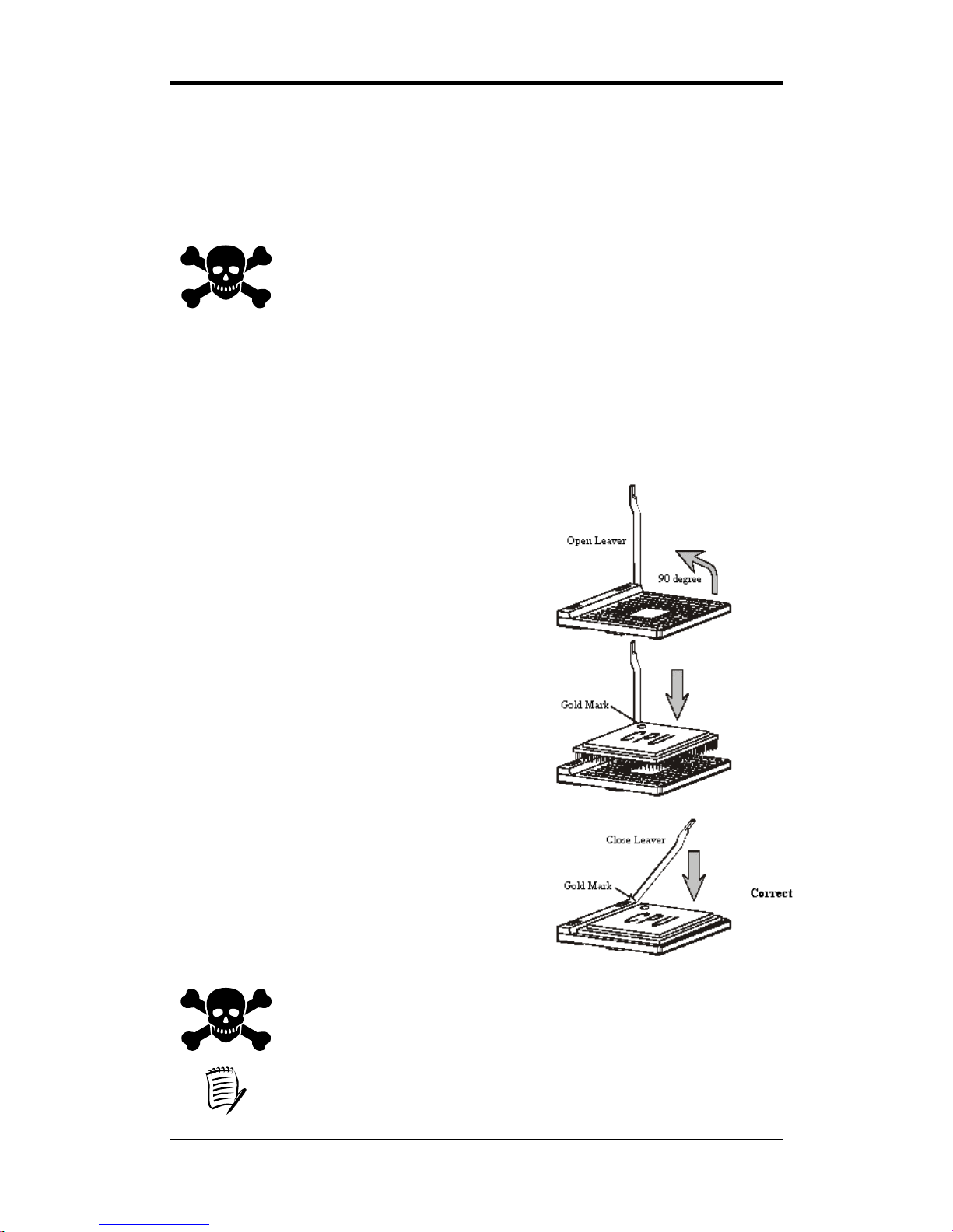
1. Locate the 478-pin CPU socket on the motherboard.
2. Unlock the socket by pressing the lever sideways, and
then open it up to a 90-degree angle.
3. Locate a Gold Mark on the top surface of the CPU,
which is close to one of the CPU corners. The same
corner will also be cut off, leaving a noticeable notch
in the CPU's corner. These markings indicate Pin 1 on
the CPU.
4. Gently insert the CPU with Gold Mark/Pin 1 at the
same corner of Socket 478, which is located close to
the end of the lever. Allow the weight of the CPU to
push itself into place. Do not apply extra pressure as
doing so may result in damaging your CPU.
5. When the CPU is correctly inserted, close the lever
with your finger on to of the CPU to make sure the
CPU is properly embedded into the socket.
6. Insert an appropriate heat sink and fan for proper Heat
dispatch.
Installing a standard Intel® specified heat sink with cooling fan is
necessary for proper heat dissipation from your CPU. Failing to install
these items may result in overheating and possible burnout of your CPU.
In order to boot up with a newly installed CPU, AC Power must be
switched off before installation.
7

Chapter 3
2-2 Setting your CPU’s Parameters
Intel Hyper-Threading Technology
Basic requirements for Intel’s Hyper-Threading Technology:
CPU: An Intel® Pentium® 4 Processor with HT Technology;
Chipset: An Intel® Chipset that supports HT Technology;
BIOS: A BIOS that supports HT Technology and has it enabled; and
OS: An operating system that supports HT Technology.
Electrical/Power Requirements for the Intel Celeron Processor
Specifications for Celeron 400 MHz FSB
- See the latest Celeron Processor EMTS for specifications on other speeds
Frequency VID (V)
Max
ICC Max
(A)
TDP (W) Tcase Min(C) Tcase Max(C)
2.30 GHz
(1,3)
1.525 49.2 58.3 5 70
2.40 GHz
(1,3)
1.525 50.7 59.8 5 71
FMB1 (1,3)
1.525 60 64 5 70
FMB2 (2,3)
1.525 70 82 5 70
1. This processor will ship under multiple VIDs of 1.475,1.500, and 1.525 with 1.525
being the max voltage.
2. This processor will ship under multiple VIDs of 1.475,1.500,1.525, and 1.550 with
1.550 being the max voltage.
3. ICC, TDP, and Tcase are specified for highest VID only.
Refer to the Intel Celeron Processor with 128 KB L2 Cache on 0.13 Micron Process
EMTS Addendum: 400 MHz System Bus Specifications for details.
8

Chapter 3
Boxed Processor FSB Chipset Support
800 MHz FSB processors require a new chipset
Willamette (0.18) processors are not supported on 875/865 chipsets
Processor FSB HTT Supporting
Chipsets
Non-Supporting
Chipsets
Intel Pentium 4 Processor
800 MHz Yes 875P, 865G/PE 865P, 850E,
845(all)
Intel Pentium 4 Processor
533 MHz Yes 865G/PE/P, 850E,
845(all)
845GL
Intel Pentium 4 Processor
(1.6AGHz, 1.8AGHz,
2.0AGHz and above)
Intel Celeron Processor
(2.0GHz and above)
533 MHz& 400
MHz
No 865G/PE/P, 850E,
845(all)
N/A
Intel Pentium 4 Processor
(2.0GHz, 1.8 GHz,
1.6GHz and below)
Intel Celeron Processor
(1.8GHz and below)
400 MHz No 850E, 845(all) 865 (all), 875P
Frequency Configuration:
With the latest technology this motherboard enables users to setup main board’s
CPU parameters through an easy-to-use BIOS setup procedure. Now it is no longer
necessary to change the various jumper settings as on conventional motherboard.
After installing all your hardware into your PC system, you can manually configure
your CPU clock ratio and CPU clock according to your processor’s specifications:
After turning on your system’s power, enable the CMOS Setup Utility by pressing
[Delete] when your BIOS identification screen appears. Then go to Frequency/
Voltage control option and select your CPU clock ratio and CPU clock speed (please
refer to Chapter 3 for more details).
If you install a CPU on this motherboard, you must set the [External Clock
Frequency] JP3/JP3A according to your processor types (See Section 2.4).
9

Chapter 3
How to Derive your CPU Core Speed?
CPU Core Speed = CPU Clock * Core/Bus Ratio
You do not need to change voltage settings because this board will
automatically set your CPU voltage.
Overclockability:
This motherboard is designed to support overclocking ability. However,
please make sure your peripherals are able to tolerate such abnormal
settings while CPU clock speed is overclocked. Any attempt to operate
beyond product specifications is not recommended. We are not
responsible for damages caused by inadequate operation or settings
beyond product specifications.
10

Chapter 3
2-3 Main Memory Configuration
This motherboard provides four 184pin Double Data Rate (DDR) Dual-In-line
Memory Modules (DIMM) slots, which supports PC2100/2700/3200 DDR SDRAM
modules up to 4GB. Install at least one DIMM module on the slots. Memory
modules can be installed on the slots in any order. You can install either single- or
double-sided modules to meet your own needs.
To install your DDR Modules please follow these steps below:
1. Unlock a DIMM socket by pressing the retaining clips outward. The DDR Modules
has only one notch at the center of module. The DDR module will only fit in the right
position.
2. Insert the DDR Module vertically into the DIMM slot, with the correct alignment.
Then push it in until the golden finger on the memory module is deeply inserted into
the socket.
3. The plastic clip on each side of the DIMM slot will automatically close to hold the
DDR Modules in place.
11

Chapter 3
Memory Channel Modes
Single Channel /
Virtual Single Channel
Dual Channel
DIMM Population
No restrictions Matching DIMM pairs
Rank (Row) Size
Size of one side of the
DIMM populated in the
channel
(64MB – 512MB)
2x the size of one side of
the DIMM populated in the
channel (A or B)
(128MB – 1GB)
Number of Ranks (Rows)
8 maximum 4 maximum
Channel Size
64 bits 128 bits
Page Size
Size read from DIMM
(4KB, 8KB, 16KB)
2 x Size read from DIMM
(8KB, 16KB, 32KB)
Burst Length
4 or 8 4
Single Channel Mode
Single Channel (SC) mode is also referred to as Virtual Single Channel (VSC)
mode.
Dual Channel Mode
Memory Channel DIMM Slot Number
DIMM 1
Channel A
DIMM 2
DIMM 3
Channel B
DIMM 4
12

Chapter 3
The following conditions must be met:
–Matched DIMM configuration in each channel
•Same Density (128MB, 256MB, 512MB, etc.)
•Same DRAM technology (128Mb, 256Mb, or 512Mb)
•Same DRAM bus width (x8 or x16)
•Both either single-sided or dual-sided
–Matched in both Channel A and Channel B memory channels
•Populate symmetrical memory slots (Slot 0 or Slot 1)
The following conditions do not
need to be met:
–Same brand
–Same timing specifications
–Same DDR speed
Symmetrical DIMMs must
be identical for optimal performance
–Same DIMM density, eg 128MB, 256MB, 512MB, etc.
–Same DRAM Technology, eg 128M-bit, 256M-bit, etc.
–Same DRAM bus width, eg x8 or x16
–Single Sided or Dual Sided
Note: Memory interface speed will be set to lowest speed of memory populated
Memory Characteristics
Optimize performance for single or dual channel is obtained with matched DIMM
population
Table below shows DIMMs with same Organization and Density, but are non-matching as
bus width, technology and/or external banks are different
–Mixing these DIMMs will put platform into single channel mode
13

Chapter 3
Maximizing Performance
Optimal configurations for highest performance:
–Matched, DDR400, Double-sided DIMMs
–Dual Channel Mode (Symmetrical DIMM population)
–Matched, DDR400, Dual Channel Mode
When not using DDR400, highest performing configuration:
–Symmetrical DIMM population with matched double-sided DIMMs
–Lightly loaded memory population aids in higher performance
–x8 Bus Width and lower DIMM cache latency also assists in higher performance
Dual Channel memory configuration provides higher performance than Single
Channel configurations
Matched DIMMs need to have identical density, DRAM technology, DRAM bus
width, and equal number of memory banks
Optimal platform performance with Dual Channel, DDR400, matched DIMMs
– Fully loaded configurations can be single or double- sided DIMMs
– Lightly loaded configurations need to be double-sided DIMMs
When not using DDR400, best performance obtained with
– Symmetrical DIMM population and matched double-sided DIMMs
– Lightly loaded configuration
14

Chapter 3
2-4 Connector and Jumper Reference Chart
Jump Connector Function Page
PW1 / 2 ATX Power Supply Connector 16
CN1A Front Panel (Power / Rest / SPK…etc.) Connector 17
FD1 Floppy Connector 18
IDE1 / 2 IDE Hard-Disk Connector 19
JP1 CMOS Clear Jumper 19
JP6 / 6A
Disable/Enable USB 0/1, 2/3 Device Power ON
Jumper
20
FAN 1 / 2 / 3 / 4
CPU / System / Case/ North Bridge Cooling Fan
Connector (12V)
20
CN5 / 5A Wake on LAN / Modem Connector 21
CN17 Blue LED Connector (5V) 22
CN23 / 23A CBOX™2 Front USB Connector 22
CN24 CBOX™2 Front Audio Connector 23
CN25 CBOX™2 DigiDoc System Display Connector 23
IR1 IR Connector 24
CN26/26A/26B IEEE1394 Connector 24
JP3 / 3A CPU Front Side Bus setting 25
SATA1 / 2 Serial ATA 25
JP23 Green LED Mode Jumper 26
CN2/2A CD-ROM Audio-in Connector 26
CN3 Auxiliary Audio-in Connector 27
CN4B 6 Channel KIT Connector 27
CN9A Chassis Open Alarm Connector 28
CN27 Game Port 28
15

Chapter 3
2-5 Connector and Jumper Settings
Connectors are used to link the system board with other parts of the system,
including power supply, keyboard, and the various controllers on the front panel of
the system case.
The power supply connector is the last connection to be made while
installing a motherboard. Before connecting the power supply, please
make sure it is not connected to the power source.
All cables that provided by CHAINTECH come with a security-proof.
PW 1 / 2 (ATX Power Supply Connector):
The power cord leading from the system's power supply to the external power
source must be the very last part connected when assembling a system. The ATX
power supply provides a single 20-pin connector interface, which incorporates
standard +/-5V, +/-12V, optional 3.3V and Soft-power signals. The Soft power signal,
a 5V trickle supply is continuously supplied when AC power is available. When the
system is in Soft-Off mode, this trickle supply maintains the system in its minimum
power state.
The ATX 12V power supply has a new +12V (4-pin) and +5V / 3.3V (6-pin)
auxiliary power connector to enable the delivery of more +12 VDC and + 5/ 3.3V
VDC current to the motherboard.
Power-On By Modem:
While in Soft-Off state, if an external modem ring-up signal is detected, the system
will be activated and therefore can be remotely accessed. You may enable this
function in BIOS's Power Management Setup menu. (See section 3. 5)
16

Chapter 3
Blinking LED in Suspend Mode:
While in Suspend mode, the LED light on the front panel of your computer will
flash. Suspend mode is entered by pressing the Green Override Power Button
on
your ATX case, or by enabling the Power Management and Suspend Mode options
in BIOS's Power Management menu. (See section 3.5)
Poly-fuse Over Current Protection:
The poly-fuse protects the system from dangerous voltages that the system might be
exposed to via keyboards or USB connectors. In case of such an exposure, the
poly-fuse will immediately be disconnected from the circuit just like a normal fuse.
After being disconnected for a certain period of time, the poly-fuse will return to its
normal state and the keyboard or USB connector can function properly again.
Unlike conventional fuses, the poly-fuse will not need to be replaced, relieving users
from such inconveniences.
CN1A (Front Panel Connector):
1. PWR-SW (Over-ride Power Button Connector):
The power button on the ATX chassis can be used as a normal power switch as
well as a device to activate the Advanced Power Management Suspend mode. This
is a power-saving mode used for saving electricity when the computer is idle for
long periods of time. The Soft-OFF by PWR-BTTN function in BIOS's Power
Management Setup menu must be set to [Delay 4 Sec.] to activate this function.
When the Soft-OFF by PWR-BTTN function is enabled, pressing the power button
rapidly will switch the system to Suspend mode. Any occurrence of external
activities such as pressing any keys on the keyboard or moving the mouse will
bring the system back to Full-On. Pushing the button while in Full-On mode for
more than [4 seconds] will switch the system completely off. See Over-ride Power
Button Operation diagram.
17

Chapter 3
2. P-LED (Power LED Connector):
The power indicator LED shows the system's power status. It is important to pay
attention to the correct cable and pin orientation (i.e. Be careful not to reverse the
order of these two connectors.)
3. G-BTN/G-LED (Green Button Switch/LED Connector):
Some ATX cases provide a Green button switch, which is used to put the system in
Suspend mode. While in Suspend mode, the power supply to the system is reduced
to a trickle, the CPU clock is stopped, and the CPU core is in its minimum power
state. The system is activated whenever the keyboard or mouse is touched. The
system will resume in various ways as defined by Power Management Setup screen
in BIOS.
For Green LED connector please refer to Section 2.7 CBOX™ 2
4. RESET (System Reset Switch Connector):
This connector should be connected to the reset switch on the front panel of the
system case. The reset switch allows you to restart the system without turning the
power off.
5. SPEAKER (Speaker Connector):
This 4-pin connector connects to the case-mounted speakers.
6. HD-LED (IDE - Activity LED Connector):
The IDE- activity LED lights up whenever the system reads/writes to the IDE
devices.
FD1 (Floppy Connector)
The motherboard provides a standard floppy disk drive connector that supports
360K, 720K, 1.2M, 1.44M and 2.88M floppy disk types. It is connected to a floppy
disk drive of 34 pins .
18
Chapter 3
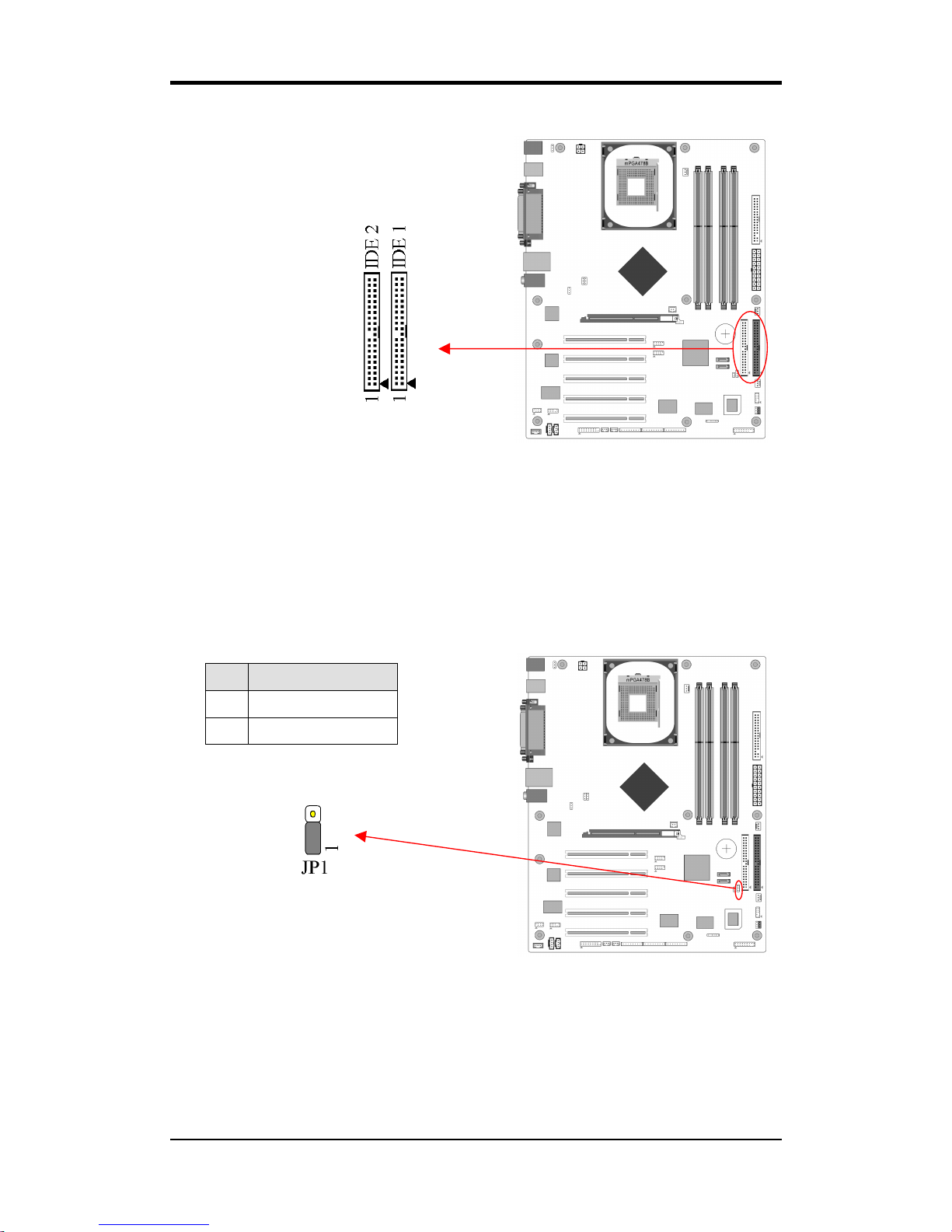
IDE 1/2 (IDE Hard-Disk Connector)
The motherboard has a 32-bit Enhanced PCI IDE and Ultra ATA66/100 controller
that provides PIO mode 0~4, Bus Master, and Ultra ATA66/100 function. This
connector is used for connecting 40 pins of ATAPI devices.
IDE 1 only connects two IDE devices. (Primary Master/Slave)
IDE 2 only connects two IDE devices. (Secondary Master/Slave)
Please refer to Section 2-6 Serial ATA and Parallel ATA for details.
JP1 (CMOS Clear Jumper):
Pin Definition
1-2 Normal (default)
2-3 Clear CMOS Data
There is a CMOS RAM on board that has a power supply from external battery to
keep the data and system configuration. To clear the contents of the CMOS, please
follow the steps below.
1. Disconnect the system power supply from the power source.
2. Set the jumper cap at location [2-3] for <5 seconds>, and then set it back to the
default position.
19

Chapter 3
3. Connect the system's power and then start the system.
4. Enter BIOS's CMOS Setup Utility and choose Load Setup Defaults. Type [Y] and
then press [Enter] to continue.
5. Set the system configuration in the Standard CMOS Setup menu.
JP6/JP6A (Enable/Disable USB 0/1, 2/3 Device Power ON Jumper)
Pin Definition
1-2 Disable (default)
2-3 Enable
JP6 USB 0/1 JP6A USB 2/3
An USB keyboard hot key or an USB mouse-click can activate this board. To use
this function, select a hot key of your choice at the USB Resume from S3 option
under Wake Up Events in the BIOS's Power On Management screen. You must also
set this jumper's cap to pins 2-3 to use this function.
FAN1/2/3/4 (CPU/System/ North Bridge Cooling Fan Connectors):
20

Chapter 3
The board's hardware management is able to detect the CPU and system fan speed in
rpm (revolutions per minute). The wiring and plugging may vary depending on the
manufacturer. On standard fans, the red is positive (+12V), the black is ground, and
the yellow wire is the rotation signal. Connect the north-bridge cooling fan to FAN3.
CN5 [WOL (Wake-on-LAN) Connector]:
Enable the Wake Up On LAN selection in BIOS's Power Management Menu to use
this function. The capability to remotely manage PCs over networks is a significant
factor in reducing administrative and ownership costs. Magic Packet technology is
designed with WOL ability to LAN controllers. This header is used to connect an
add-in NIC (Network Interface Card) that provides WOL function to the
motherboard.
CN5A [WOM (Wake-on-Modem) Connector]:
21
Chapter 3
Enable the Wake Up On Modem selection in BIOS's Power Management Menu to
activate this function. This header is used to connect an add-in modem card, which
provides WOM function to the motherboard.
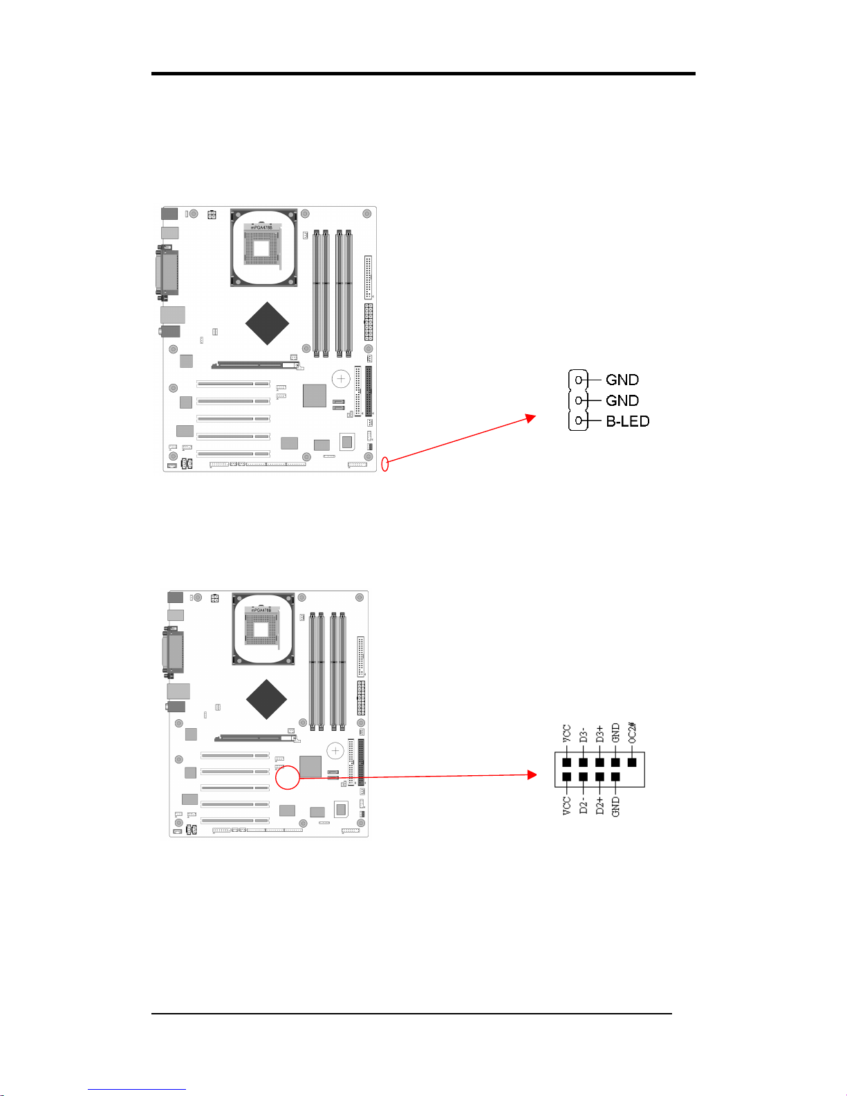
CN17 (Blue LED Connector)
This feature works exactly the same as the power indicator LED, of which both
indicate the system’s power status. The only difference is that this one is blue while
the other one is red.
CN23/CN23A (CBOX™ 2 Front USB Connector for USB 4/5 and 6/7):
USB Port 4/5 CN23 USB Port 6/7 CN23A
If you want to use a USB Keyboard, you must enable the USB keyboard support
function in BIOS's Integrated Peripherals menu (See Section 3.4). This board
contains a USB Host controller and a root hub with two connectors is also included
for an optional USB Adaptor (USB 4/5 and 6/7).
22

Chapter 3
CN24 (CBOX™ 2 Front Audio Connector):
This connector gives you the option of a front-panel audio-jack cable ext. to be
plugged into a special custom-designed system case.
Simply remove the two jumper caps at pins [5-6] and [9-10] then plug it into the
(optional) cable ext. connector. Pins [5-6] and [9-10] are shorted (default) to enable
the back-panel audio function.
CN25 (CBOX™ 2 DigiDoc System Display Connector):
CBOX™ 2 features CHAINTECH’s exclusive DigiDoc, the most advanced system
diagnostic monitoring display.
80-PORT diagnostic display during POST at system boot up!
CPU temperature monitoring, your system stays cool always!
DigiDoc is the doctor for your system!
Refer to Appendix Digidoc 80-Port POST Error Code List for its details.
23

Chapter 3
IR 1 (IR Connector):
Select the UART port used in UART Mode from BIOS's Integrated Peripherals
menu to support IR function. (See section 3.4 Super I/O Device of Integrated
Peripherals)
CN26/26A/26B (IEEE1394 Connector)
Attach the IEEE 1394 serial connector cable to 6GFKIT and CBOX™ 2 Front
panel.
24

Chapter 3
JP3 / 3A (CPU Front Side Bus setting)
EXT. Clock JP3 JP3A
Default 1-2 1-2
100MHz 2-3 2-3
133MHz OPEN 2-3
166MHz OPEN OPEN
200MHz 2-3 OPEN
This function allows you to set the CPU’s FSB. The default setting is at pins [1-2],
and your CPU’s FSB will be automatically detected.
It is recommended that you leave the default settings to prevent any burnout
on your CPU.
SATA1/2 (Serial ATA Connector):
This can connect to new IDE device; it supports ATA 150MB/sec.
Please refer to Section 2-6 Serial ATA and Parallel ATA for details.
25

Chapter 3
JP23 (Green LED Mode Jumper)
Pin Definition
1-2 Normal (default)
2-3 Reserve
This is for setting up Green LED flash mode. (Optional)
CN2/CN2A (CD-ROM Audio-in Connector)
Use the audio cable enclosed with your CD-ROM disk drive to connect the
CD-ROM to your motherboard. This will enable your CD-ROM's audio function.
26

Chapter 3
CN3 (Auxiliary Audio-in Connector) (Optional)
This connector is for Auxiliary Audio-in Device.
CN4B (AC3 Center / Surround + Bass Connector)
This connector must be connected to 6GFKIT.
27

Chapter 3
CN9A (Chassis Open Alarm Connector)
This connector provides a buzzer sound when an attempt to open the chassis occurs.
Note: Only certain chassis provides this function.
CN27 Game Port Connector
This connector must be connected to 6GFKIT.
28

Chapter 3
2-6 Serial ATA and Parallel ATA
SATA & PATA configurations
1. Compatible mode -
Older OSs don’t support switch to native mode (DOS, Win2K, Win98/ME…)
should set SATA and PATA to Compatible Mode.
Maximum 4 ATA devices
Combine mode and Non-Combine mode
2. Enhanced mode –
New OS that support switch to native mode (WinXP, Windows.NET Server)
can set SATA and PATA to Enhanced Mode.
Comprehend both legacy and /or native modes
Maximum 6 ATA devices (4 for PATA, 2 for SATA)
Proper support: BIOS provide a BIOS setup option for Enhanced mode or
Compatible mode user selection.
SATA- Compatible mode
Option 1 – Non-Combined Mode
P-ATA devices only
Maximum of 4
Option 2 – Non-Combined Mode
S-ATA devices only
Maximum of 2
29

Chapter 3
Option 3 – Combined Mode
S-ATA devices
P-ATA devices
Maximum of 2 Each
(3a) (3b)
(3c) (3d)
Enhanced Mode
Enable S-ATA & P-ATA
Max 6 ATA (4 P-ATA + 2 S-ATA)
30

Chapter 3
2-7 CBOX™ 2 and 6GFKIT Setup
1. Gently insert CBOX™ 2 into the regular 5-1/4” drive bay at the front of system
chassis and securely tighten the side screws.
2. Connect Motherboard to CBOX™ 2:
Function Motherboard CBOX™2 6GFKIT
USB 4 & 5 CN23 CN1
USB 6 & 7 CN23A CN2
*Front Audio CN24 CN3
IEEE 1394 CN26/26A/26B CN4 CN28/CN29
80 Port Display CN25 CN6
6 channel Kit connector CN4B CN4B
Game Port CN27 CN27
Remove CN24 Jumper Caps on motherboard 5-6, 9-10 before installation.
USB Cable (10 pin) x 2
Front Audio Cable (10 pin) x 1
IEEE-1394 Cable (8 pin) x 1
80 Port Display (10 pin) x 1
All cables that provided by CHAINTECH come with a security-proof.
31
Chapter 3
Chapter 3
BIOS Setup Program
Phoenix-Award BIOS ROM has a built-in setup program that allows users to modify
the basic system configuration. This information is stored in CMOS RAM so that it
can retain the setup information even when the power is turned off.
To enter the Phoenix-Award BIOS setup program:
1. Press [Delete] when you Power on or Reboot the computer system. (i.e. After
the Intel Pentium 4 logo appears at the center of the screen, please press [Delete]
to enter the BIOS setup program).
2. Press [Tab] to enter the POST (Power On Self Test) screen that has a small logo
at the top right side of the screen, and then press [Delete] to enter the BIOS
setup program.
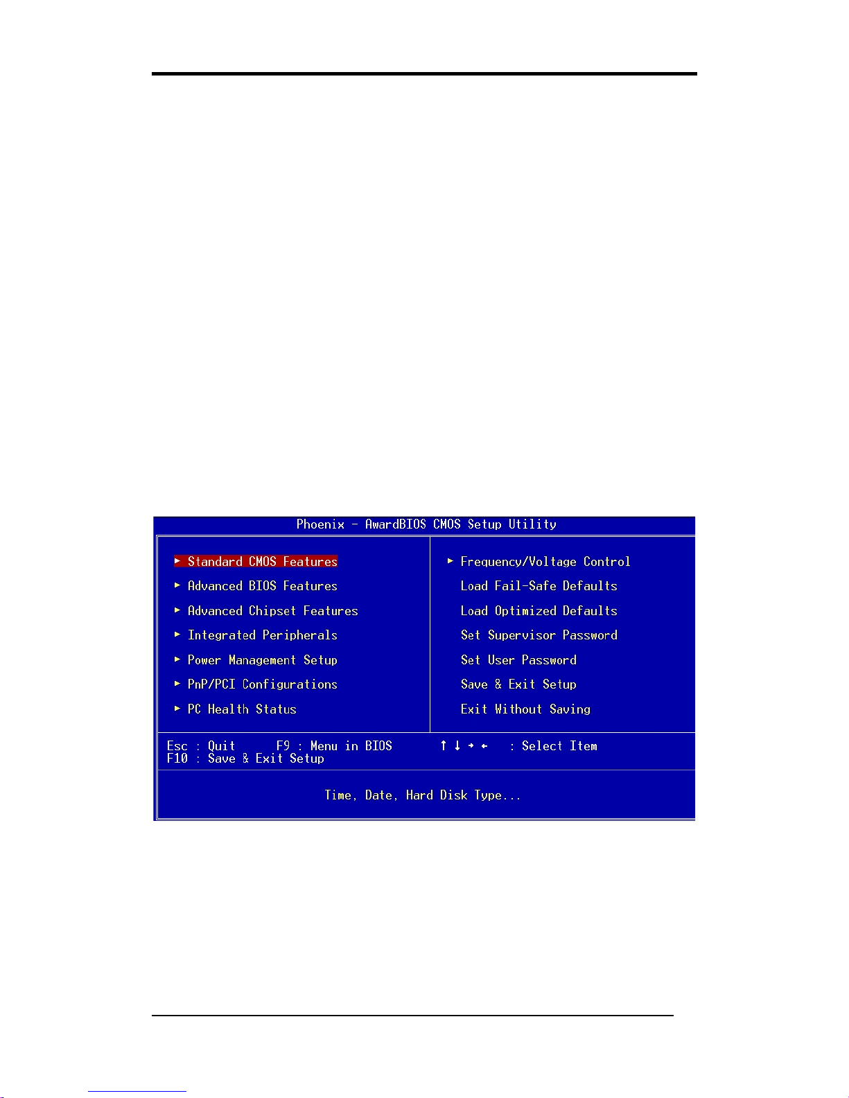
The primary screen as shown in Figure 3-1 is a list of the menus and functions
available in the setup program. Select the desired item by using arrow keys and
press [Enter] to make the changes. Operating commands are located at the bottom
of this and all other BIOS screens. When a field is highlighted, on-line help
information is displayed on the right side of the screen.
Figure 3-1 Setup Program Initial Screen
32
Chapter 3
3-1 Standard CMOS Setup
The Standard CMOS Setup allows users to configure system components such as
hard-disk drive, floppy-disk drive and video display as well as date, time and boot
up error signaling. This configuration menu should be changed when installing a
motherboard for the first time, or changing hardware such as HDD, FDD, and video
display in your system, or when the CMOS data was lost or corrupted. Choose the
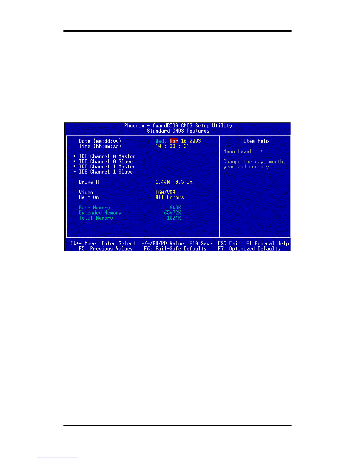
Standard CMOS Setup option from the CMOS Setup Utility menu (Figure 3-1) to
display the following screen:
Figure 3-2 Standard CMOS Feature Screen
Date/Time:
Set the date and time of the system. Do not skip this function as all of your timed
events such as power management, saving files, etc are based on this timer.
IDE (Channel 0/1; Master/Slave):
This category identifies up to four IDE hard-disk drives that have been installed in
the computer. This section does not show information on other IDE devices such as
CD-ROM drives or other hard drive types such as SCSI drive.
Drive A:
Select different Floppy device Model. Available options are [None], [360K, 5-1/4
in], [1.2M, 5-1/4 in], [720k, 3-1/2 in], [1.44M, 3-1/2 in], and [2.88M, 3-1/2 in].
Video:
Select the type of video adapter present in your system. You can ignore this setting if
you are using a VGA monitor; VGA BIOS will automatically configure this setting.
Halt On:
When the system is powered on, BIOS performs a series of diagnostic tests called
33

Chapter 3
POST (Power On Self Test). This function stops the computer if BIOS detects a
hardware error. You can tell BIOS to halt on all errors, no errors, or not to halt on
specific errors.
3-2 Advanced BIOS Features
By choosing the Advanced BIOS Features option from the CMOS Setup Utility
menu (Figure 3-1), the screen that lists the manufacturer's default values for the
motherboard is displayed below.
Figure 3-3 Advanced BIOS Feature Screen
Hard Disk Boot Priority:
Select priority of the hard disk boot device.
Virus Warning:
When you set it as enabled, you receive a warning message if a program
(specifically, a virus) attempts to write to the boot sector or the partition table of the
hard-disk drive.
Many disk diagnostic programs that access the boot sector table can trigger the
virus-warning message. If you plan to run such a program, we recommend that
you first disable the virus warning.
CPU L1 & L2 Cache:
Cache memory is much faster than conventional DRAM system memory. These
fields allow you to enable or disable the CPUs Level 1 built-in cache and Level 2
external cache. Both settings are left as Enabled to significantly increase the
34

Chapter 3
performance of your computer.
Hyper-Threading Technology
Available options are [Enabled] and [Disabled]. Select [Enable] to support
Hyper-Threading Technology and vice versa.
Quick Power On Self Test:
Enable this function to reduce the amount of time required to run the POST (Power
On Self Test). BIOS will save time by skipping some items during POST. It is
recommended that you disable this setting. Discovering a problem during boot up is
better than loosing data during your work.
First/Second/Third/Boot Other Device:
This option sets the sequence of drives BIOS attempts to boot from after POST
completes. BIOS will search these drives for an operating system.
Boot up Floppy Seek:
This is a set up check for floppy power-on after starting the computer system.
Boot Up NumLock Status:
This function defines the keyboard's number pad as number keys or arrow keys. If it
is set at On the number keys will be activated, if it is set at Off the arrow keys will
be activated.
Gate A20 Option:
This allows you to set the Gate A20 status. When set to [Fast], Gate A20 is cont
rolled by chipset. When set to [Normal], Gate A20 is cont rolled by a specific pin
from the keyboard controller. Available options are [Fast] and [Normal].
Keyboard Interface:
1. Typematic Rate Setting
When enabled, you can set the following two-typematic control items. When
disabled, the keyboard controller determines keystrokes arbitrarily in your system.
2. Typematic Rate (Chars/Sec)
The typematic rate sets the rate at which characters on the screen repeat when a key
is pressed and held down.
3. Typematic Delay (Msec)
The typematic delay sets how long after you press a key that a character begins
repeating.
Security Option:
The Supervisor and/or User Password functions shown in Figure 3-1 must be set to
35

Chapter 3
take advantage of this function. See Section 3.11 for password setting information.
When the Security Option is set to System, a password must be entered to boot up
the system or enter the BIOS setup program. When the Security Option is set to
Setup, a password is required to enter the BIOS setup program.
APIC Mode
In order to comply with PC2001 standard, the system is designed to run in APIC
(Advanced Programmable Interrupt Controller) mode. Enabling APIC mode
will increase the available IRQ resources for the system. Available options are
[Enabled] and [Disabled].
MPS Version Control For OS
This item allows you to select which MPS (Multi-Processor Specification) version
is used for the operating system. You need to select the MPS version that is
supported by your operating system. To find out which version to use, consult the
vendor of your operating system. Available options are [1.4] and [1.1].
OS Select (For DRAM >64MB):
If your system's DRAM is larger than 64MB and you are running OS/2, select OS/2
as the item value. Otherwise, set the item value to Non-OS/2 for all other operating
systems.
Small Logo (EPA) Show
This setup allows photo that is EPA. Logo.
36

Chapter 3
3-3 Advanced Chipset Features
By choosing the [Advanced Chipset Features] option from the CMOS Setup
Utility menu (Figure 3-1), the screen that lists the manufacturer's default values for
the motherboard is displayed below.
Figure 3-4 Advanced Chipset Features
All of the above settings have been determined by the motherboard
manufacturer and should not be changed unless you are absolutely sure of
what you are doing. Explanations of the DRAM timing and chipset features
setup are lengthy, highly technical and beyond the scope of this manual. Below
are some brief descriptions of the functions in the Setup menu.
DRAM Timing Selectable
The function allows you to enable or disable the DRAM timing by SPD. It is
recommended to keep the default setting for a stable system operation.
CAS Latency Time
This item controls the latency between DRAM read command and the time the data
actually becomes available.
Active to Precharge Delay
This item controls the number of DRAM clocks used for DRAM parameters.
DRAM RAS# to CAS# Delay
This item controls the latency between DRAM active command and read/write
command.
37

Chapter 3
DRAM RAS# Precharge
This item controls the idle clocks after issuing Precharge command to the DRAM.
Memory Frequency For
Please leave the default system setting as [Auto] for a stable system operation.
WARNING
Overclockability:
This motherboard is designed to support overclocking ability.
However, please make sure your peripherals are able to
tolerate such abnormal setting, while CPU clock speed is
overclocked. Any attempt to operate beyond product
specifications is not recommended. We are not responsible for
damages or risks caused by inadequate operation or settings
beyond product specifications
.
System BIOS cacheable
Enabling this function allows caching of the system BIOS ROM at F0000h-FFFFFh,
which results in better system performance. However, if any program writes to this
memory area, a system error may result. It is advisable to leave it in default setting.
Caching the system BIOS results in better performance than shadowing the system
BIOS.
Video BIOS Cacheable
Enabling this function will allows caching of the video BIOS, resulting in better
system performance. However, if any programs write to this memory area, a system
error may occur.
Memory Hole at 15M-16M
Enabling this function will reserve the memory address space between 15MB and
16MB for ISA expansion cards. However, it will also result in not allowing the
system to have access to memory above 16MB. Please note that some expansion cards
require this setting to be enabled. The default setting is Disabled. If Auto
Configuration is enabled, you must set the DRAM timing function to 60ns or 70ns,
depending on the type of DRAM you install.
Delay Prior to Thermal
Available options are 4, 8, 16 and 32 min.
AGP Aperture Size (MB):
This function determines the amount of system memory that is given to the AGP
card. Available options ranges from 4MB to 256MB. This is a dynamic memory
38
Chapter 3
allocation in that the AGP card will only use the amount of memory that it needs.
The remaining unused memory is also available for system usage. For example, if
16MB is allocated to the AGP card and the card only needs 8MB, the remaining
8MB will be available for system usage.
Init Display First
This function allows users to choose between AGP and PCI slots to initialize
monitor display.
3-4 Integrated Peripherals
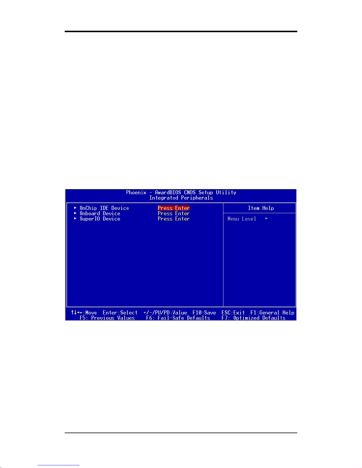
This section provides information on setting up the peripheral devices. By choosing
the Integrated Peripherals option from the CMOS Setup Utility menu (Figure 3-1),
the screen that lists the manufacturer's default values for the motherboard is
displayed below.
Figure 3-5 Integrated Peripherals Screen
OnChip IDE Device:
Press [Enter] to enter the sub-menu, which contains the following items for some
advanced control:
1. IDE HDD Block Mode
Block mode is also called block transfer, multiple commands, or multiple sector
read/write. If your IDE hard-drive supports block mode, select Enabled to
auto-detect the optimal number of block read/writes per sector the drive can
39

Chapter 3
support.
2. On-Chip Primary/Secondary PCI IDE
You can set this to disable the On Chip IDE controller if you are going to add a
higher performance IDE board.
3. IDE Primary/Secondary Master/Slave PIO:
The four IDE PIO (programmed Input/Output) fields let you set a PIO mode (0-4)
for each IDE device that the internal PCI IDE interface supports. Modes 0 through
4 provide successively increased performance. In Auto mode, the system
automatically determines the best mode for each device.
4. IDE Primary/Secondary Master/Slave UDMA:
Ultra DMA implementation is possible only if your IDE device supports it and
your operating environment contains a DMA driver. If both your hard drive and
software support Ultra DMA, select [Auto] to enable BIOS support.
5. SATA Mode
Available options are [IDE] and [RAID].
6. On-Chip Serial ATA
Available options are [Disabled], [Auto], [Combined Mode], [Enhanced Mode],
[SATA Only].
Disabled: Disabled Serial ATA controller.
Auto: Auto arrange by BIOS.
Combined Mode: Parallel ATA and serial ATA are combined. Maximum of
two IDE drives are supported.
Enhanced Mode: Enable both serial ATA and parallel ATA. Max of six
IDE drives is supported.
SATA Only: Serial ATA is operating in legacy mode.
7. Serial ATA Port 0 Mode
Please leave the default value as [Primary Master] for a stable system operation.
Onboard Device:
This section provides information for setting the on-board devices. Press [Enter] to
enter the sub-menu, which contains the following items for some advanced controls:
1. USB controller:
Enable the on-board Universal Serial Bus (USB V1.1 or V2.0) controller if you
want to connect a USB device to your system. Note that if this setting is disabled,
you can still temporarily use a USB keyboard during boot up so that you can enter
BIOS and enable this setting. If you pass the boot up stage without enabling this
function, your PS/2 keyboard will no longer work.
40

Chapter 3
2. USB 2.0 controller
This entry is for disable/enable EHCI controller only. This BIOS itself may/may
not have high speed USB support. If the BIOS has high speed USB support built in,
the support will automatically be turned on when high speed device were attached.
3. USB Keyboard Support
Select Enabled if your system uses an USB keyboard. If there is no USB keyboard,
select Disabled in this field.
4. USB Mouse Support
Select Enabled if your system uses an USB mouse. If there is no USB mouse,
select Disabled in this field.
5. CMedia Audio
By default is [6 Channels].
6. Onbd 1394
Select Enabled if your system uses an on-board IEEE1394. If there is no on-board
IEEE1394, select Disabled in this field.
7. Onbd PCI Audio
Select Enabled if your system uses an on-board PCI Audio card. If there is no
on-board PCI Audio card, select Disabled in this field.
8. Realtek LAN
Select Enabled if your system uses an on-board Realtek Lan. If there is no
on-board Realtek Lan, select Disabled in this field.
Super IO Device:
This section provides information on setting the Super I/O devices. Press [Enter] to
enter the sub-menu, which contains the following items for some advanced controls:
1. Onboard FDC Controller:
In order to use it select as Enabled if your system has a floppy-disk controller
(FDC) installed on the system board. If you install an add-in FDC or the system
has no floppy drive, choose Disabled in this field.
2. Onboard Serial Port 1/2:
Select an address and corresponding interrupt for the first and second serial ports.
Available options are [3F8/IRQ4], [2E8/IRQ3], [3E8/IRQ4], [2F8/IRQ3],
[Disabled], and [Auto].
3. UART Mode Select:
This function allows you to select an operating mode for the second serial port.
(Normal RS-232C serial port / IRDA / SCR / ASKIR 0.57-MB/sec infrared port).
41

Chapter 3
4. UR2 Duplex Mode:
Available options: [Half] and [Full].
5. Onboard Parallel Port:
Select a logical LPT port address and the corresponding interrupt for the physical
parallel port.
6. Parallel Port Mode:
Select an operating mode for the onboard parallel (printer) port. Select SPP unless
you are certain that your hardware and software support one of the other available
modes.
7. ECP Mode Use DMA:
This item automatically specifies DMA channel 1 or 3 for the parallel port when it
is set to [EPP] or [ECP+EPP] mode.
42

Chapter 3
3-5 Power Management Setup
This section provides information on the Green PC power management functions.
By choosing the Power Management Setup option from the CMOS Setup Utility
menu (Figure 3-1), the screen that lists the manufacturer's default values for the
motherboard is displayed below.
Figure 3-6 Power Management Setup
ACPI Suspend Type:
This feature allows users to select a suspend type for the operating system to turn off
unused peripheral devices such as CD-ROM player.
Run VGABIOS if S3 Resume
Available options are [Auto], [Ye s], [No].
Power Management:
Power management saves electricity while the system is idle by entering
power-saving modes.
Video Off Method:
This function serves as both screen and power savers for the monitors. See the next
function, Video Off After, for setting the video timer.
1. Blank Screen - BIOS will switch the monitor screen to blank. The electricity
saved in this mode is negligible and this function is only used as a screen saver
to prevent screen damage while the screen is idle.
2. V/H SYNC+ Blank - The system turns off the vertical and horizontal
43

Chapter 3
synchronization ports, writes blanks to the VGA buffer and the monitor's
electron gun turns off. This function requires monitors with Green features in
order to take advantage of the power-saving function. If you enable this function
and do not have a Green monitor, the result will be the same as if you had
selected Blank. This function serves as both a screen saver and a power saver.
3. DPMS - Select this option if your video card supports the Display Power
Management Signaling (DPMS) standard (i.e. if you have a monitor that
supports Green features). Use software supplied by your video subsystem to set
video power management options.
Video off in Suspend:
If it is set to [Ye s] the monitor enters power saving mode. The Power Management
function must be enabled to use this function.
Suspend Type
Available options are [Stop Grant] and [PwrOn Suspend].
MODEM Use IRQ:
If your computer has a built-in modem use this function to inform BIOS the IRQ
value occupied by the modem card. When the system is in Green mode, the modem
requires an IRQ assignment to activate the system to perform tasks. This assignment
is complaint with the APM 1.2 compliant operating systems.
Suspend Mode:
The Power Management function is set as [Enabled] to activate this function. If the
system runs in Standby mode and the Suspend timer expires, all devices regulated
by power management will shut down and the CPU speed will be 0 MHz.
HDD Power Down:
It shuts down any IDE hard disk drives in the system after an idle period. This
feature does not affect SCSI hard drives.
Soft-Off by PWR-BTTN:
When set to Delay 4 Sec., this function allows the power button to put the system in
Suspend, a power saving mode. When set to Instant-Off the Soft-Off by PWR-BTN
function is disabled and the computer turns completely off when the power button is
pressed.
Wake up Events
1. Power On by PCI / Onbd LAN:
When enabled, a PCI interface that receives a signal will activate the system from
soft off and green mode.
44

Chapter 3
2. Power On by Ring:
When enabled, a Modem will be able to receive a signal and activate the system
from soft off and green mode. You should connect the modem to the COM port and
signal your PC to power on.
3. Wake up on LAN:
When enabled, a LAN that receives a signal will activate the system from soft off
and green mode.
4. USB KB Wake –up From S3:
Allows the USB devices to activate the system from S3 power-saving modes.
Settings are [Enabled] and [Disabled].
5. Resume by Alarm:
When enabled, this setting allows the system to turn back on at specified date of
the month. User must designate date of month and time of day.
This function is only available when using an ATX power supply and the Software
Power-Off function to turn off the computer.
6. POWER ON Function:
This function gives PS/2 mouse and keyboard control to power on the system.
Available settings are [Password], [Hot KEY], [Mouse Move], [Mouse Click],
[Any KEY], [BUTTON ONLY] and [Keyboard 98].
7. KB Power ON Password:
If POWER ON function is set to [Password], then you can seta password for the
PS/2 keyboard to power on the system.
8. Hot Key Power ON:
If POWER ON function is set to [Hot Key], you can assign hot key combinations
from [Ctrl –F1] to [Ctrl-F12] for the PS/2 keyboard to power on the system.
9. PWRON after PWR-Fail
By Default is [Off].
45

Chapter 3
3-6 PNP/PCI Configurations
This section provides IRQ and DMA setting information. By choosing the PNP/PCI
Configuration option from the CMOS Setup Utility menu (Figure 3-1), the screen
that lists the manufacturer's default values for the motherboard is displayed below.
Figure 3-7 PNP/PCI Configurations
Reset Configuration Data:
Default is [Disabled]. Select Enabled to reset Extended System Configuration Data
(ESCD) if you have installed a new add-on and the system reconfiguration has
caused such a serious conflict that the OS cannot boot.
Resources Controlled By:
When set to Manual the system BIOS will not refer to ESCD for IRQ & DMA
information. Instead, it will refer to the items in the setup menu for assigning IRQ &
DMA. When set to Auto the system BIOS will refer to ESCD for all legacy
information. ESCD (Extended System Configuration Data) provides a detailed
format of the configuration data structures stored in flash memory. Each data
structure defines the resources used by a device or a card in the system. This
includes legacy and PCI/ISA PnP devices.
PCI/VGA Palette Snoop:
When set to [Enabled], multiple VGA devices operating on different buses can
handle data from CPU to each set of palette registers of every video device. Bit 5 of
the command register in the PCI device configuration space is the VGA Palette
Snoop bit (0 is disabled). Available options are [Enabled] and [Disabled].
46

Chapter 3
FDD IRQ Can Be Free:
This function allows users to choose if the FDD IRQ can be freed up. The default
setting is [Ye s ].
3-7 PC Health Status
By choosing the PC Health Status option from the CMOS Setup Utility menu
(Figure 3-1), the screen below is displayed. This field shows you the current system
temperature/external voltages input and the current CPU FAN and System FAN
operating speed.
Figure 3-8 PC Health Status
Shutdown Temperature:
This item allows you to set the shutdown temperature level for the processor. When
the processor reaches the temperature you set, the system will shutdown. This
function only works in ACPI-aware OS (such as Windows 98 / ME / 2000).
Available options are [70°C/158°F], [65°C/149°F] and [60°C/140°F]
47

Chapter 3
3-8 Frequency/Voltage Control
By choosing the Frequency/Voltage Control option from the CMOS Setup Utility
menu (Figure 3-1), the screen that lists the manufacturer's default values for the
motherboard is displayed below.
Figure 3-9 Frequency/Voltage Control
Auto Detect PCI Clk
Available options are [Enabled] and [Disabled].
Spread Spectrum
Available options are [+/- 0.35 %], [+/- 0.50%], [+/- 0.75%], [+ /- 1.00%] and
[Disabled].
CPU Clock:
This feature allows the system memory to run at specified CPU clock speed. The
default setting is at 100Mhz.
Note: This motherboard can support an overclocking of CPU clock speed up to 353
MHz, provided that the CPU clock must be set to run at 133 MHz FSB.
Overclockability:
This motherboard is designed to support overclocking ability. However,
please make sure your peripherals are able to tolerate such abnormal
setting, while CPU clock speed is overclocked. Any attempt to operate
beyond product specifications is not recommended. We are not
responsible for damages caused by inadequate operation or settings
beyond product specifications.
48

Chapter 3
Voltage Fine Tune
Please leave the default setting as [Disable] for a stable system operation. Available
options are [Enabled] and [Disabled].
3-9 Load Fail-Safe Defaults
Load Fail-Safe Defaults loads the default BIOS values directly from the CMOS
Setup Utility menu (Figure3-1). If user-defined BIOS settings are corrupted and
therefore unusable, these defaults will be loaded automatically when you turn on the
computer.
3-10 Load Optimized Defaults
Load Optimized Defaults loads the default system values directly from the CMOS
Setup Utility menu (Figure3-1). If user-defined BIOS settings are corrupted and
therefore unusable, these defaults will be loaded automatically when you turn on the
computer.
3-11
Supervisor Password & User Password Setting
There are four different variables that control password settings. The first two are
located under the Security Option function in BIOS Features Setup Menu (Figure
3-1). When the Security Option function is set to Setup, a password is required to
enter BIOS and change BIOS settings. When the Security Option function is set to
System, a password is required to enter both BIOS and computer's operating system
(For example, Windows 98) found on the boot drive.
The third and fourth variables are user password and supervisor password selected in
BIOS (Figure 3-1). The main purpose of separating users and supervisors is to allow
only the supervisor to have control over the BIOS settings. The user, on the other
hand, is only allowed to access computer's operating system and change the user
password in BIOS.
When there is no supervisor password being set, the user password controls
access to all BIOS settings.
3-12 Save and Exit Setup
If you select this and type [Y] followed by [Enter], the values entered in the setup
49

Chapter 3
utilities will be recorded in the CMOS memory of the BIOS chip.
3-13 Exit Without Saving
Selecting this option and pressing [Y] followed by [Enter] lets you exit the Setup
program without recording any new values or changing old ones.
50

Chapter 4
Chapter 4
DRIVER Setup
Insert the support CD that come with your motherboard into your CD-ROM driver or
double-click the CD drive icon in [My computer] to enter the setup screen.
4-1 Intel® IDE Bus Mastering Drivers Setup
1. Click [Intel® IDE Bus Mastering Drivers]
2. Click [Next] to start software installation.
51

Chapter 4
3. Click [Yes] to accept the license agreement
4. Select [Next] to continue.
52

Chapter 4
5. Please select [Yes] to restart computer now or [No] to restart later, and then click
on [Finish] to complete the installation.
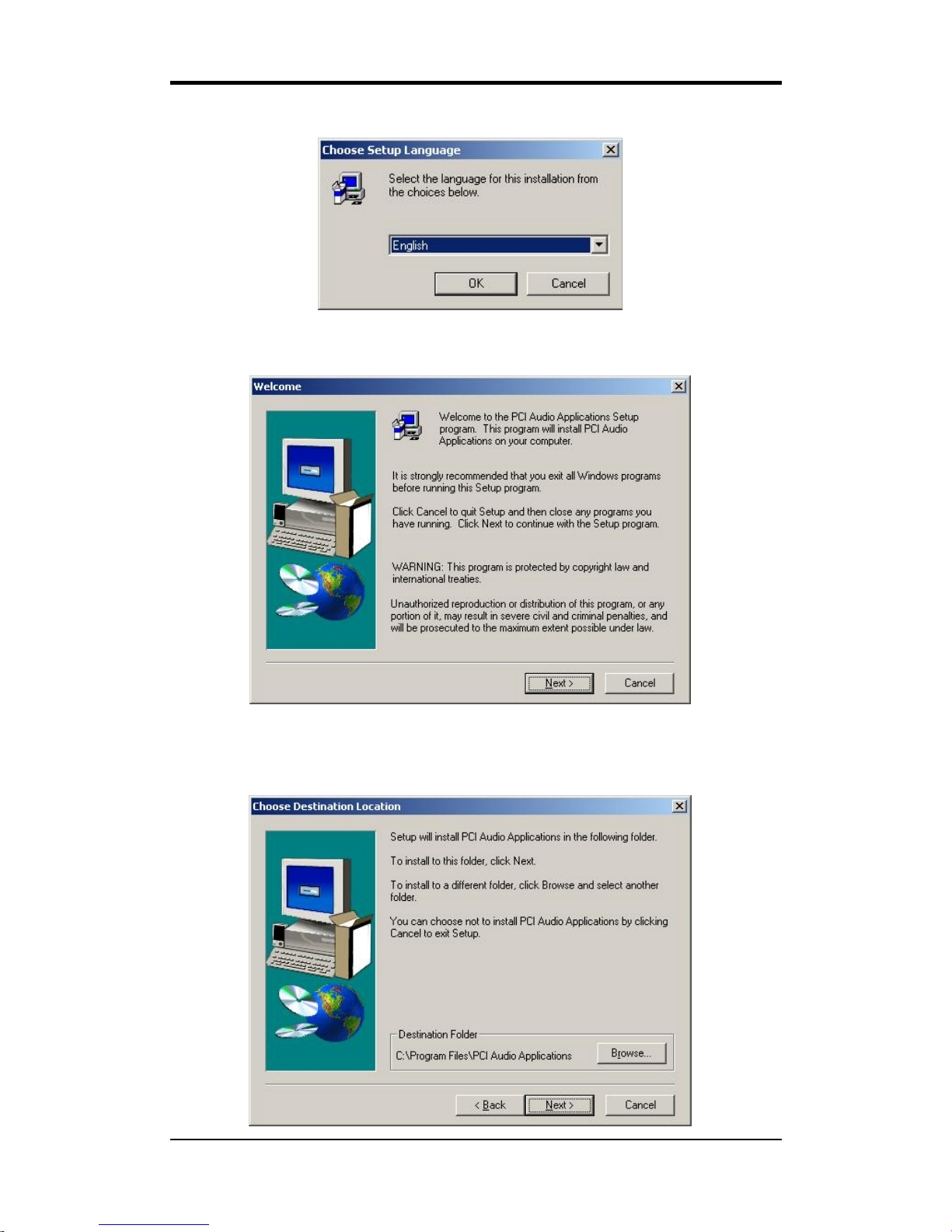
4-2 C-Media Sound Driver Setup
This section provides information on installing audio devices by choosing
[Audio Driver] from the Setup Driver menu.
1. Select [Audio driver]
53

Chapter 4
2. Select [Audio Drivers] to begin the software installation
3. Select [Install Device Driver and Applications].
54
Chapter 4
4. Select the setup language and click [OK] to continue.
5. Click [Next] to proceed.
6. Please select a folder where the program will be installed and click on [Next >] to
proceed.
55

Chapter 4
7. Please select one folder from existing list of folders and click on [Next >] to
proceed.
8. Please select [Yes] to restart computer now or [No] to restart later, and then click
[OK] to complete the installation.
56

Chapter 4
4-3 Intel® LAN Driver Setup
1. Click [LAN Driver]
2. Click [Next >] to continue.
57

Chapter 4
3. Click [Finish] to complete setup
4-4 USB 2.0 Driver
Open Device Manager and open the properties for the USB 2.0 host controller.
Select 'Update Driver'. Point the installer to the folder with the USB 2.0 drivers.
It should select the CD-ROM:\intel\usb2\win2k_XP\ich5usb2_win2k (for Win 2000
/XP or CD-ROM:\intel\usb2\win98&me (for 98se / ME) and then install the system
files. The host controller should be installed correctly when Device Manager is
updated after the install.
58

Chapter 4
Chapter 5 Audio Device Application
This sound card supports Windows 95/98/ME/NT4.0/2000 operating systems. To
start the Audio Application Program simply select from menu [Start]→[Program
Files]→[PCI Audio Applications]→[Audio Rack].
It includes the following options:
a) Audio Rack:
Which includes Audio Rack, CD Player, MIDI Player, Mixer and MP3 Player.
b) Multi-Channel Audio Demo:
(Windows NT4.0 is not supported)
Demonstrations of Multi-Channel Audio.
c) Uninstall Applications:
Which uninstalls the driver and all application programs for the Sound card.
5-1 Audio Rack
Audio Rack includes 4 control panels:
C-Media Mixer Volume
CD Player
MIDI Player
MP3 WAVE Player
You can start the Audio Rack by selecting from【Start】→【Program】→
【PCI Audio Applications】→【Audio Rack】
CD Player Outpu
t
Configuration
MIDI Player Outpu
t
Configuration
MP3 WAVE Playe
r
Configuration
Mixer Setup
59

Appendix
1. C-Media Mixer Volume
a) Volume Control
You can simply double-click the icon located at button right corner of
Windows to open the C-Media Mixer volume control.
This control panel includes Master Volume, CD Audio, Microphone, WAVE,
SW Synth, A/V (AUX) In, MONO IN, and LINE IN.
b) Mixer Recording Control
This control panel includes CD Audio, Microphone, WAVE, Stereo Mix,
A/V (AUX IN), and LINE IN.
c) Help
60

Appendix
d) Mixer Advance Setting:
1) SPDIF:
a) Output:
S/PDIF Playback:
It activates SPDIF OUT. (SPDIF Out only applies to earphone
and 2 speakers.)
Sampling Rate:
Transfer the Wave file from computer to any digital media
devices through optical fiber, e.g. MD or DAT Advanced media
devices. (SPDIF-out only supports 44.1 kHz and 48 kHz High
frequency rates.)
b) Input:
Loop back (to digital out):
Transfer the Wave file from the computer to any digital media
devices through optical fiber, e.g. MD or DAT Advanced media
devices. (SPDIF-out only supports 44.1 kHz and 48 kHz High
frequency rates.)
Monitoring (to analog out):
Monitors the SPDIF IN signal (Digital SPDIF signals use the analog
output through LINE OUT to make sound.)
Validity Detection:
Select this option to detect and check the validity of the fiber signal.
61

Appendix
Format: Select between Normal and Reverse.
Device: For device features select from S/PDIF #1 and S/PDIF
#2.
Copyright Protection: Audio files have copyrights. Please
select this option to prevent pirate copies.
2) Speakers:
Headset & 2 channel speaker setup
4 channel speaker setup
62

Appendix
6 channel speaker setup
User 4ch XeaR mode setup
User 6ch XeaR mode setup
63

Appendix
3) Volume:
4) Sound Effect:
5) Option:
【Enable Hot-Key Setting】
This provides Hot-Keys settings of Volume control, Mute, and Display.
【Enable Microphone Booster】
Enable the microphone’s electrical circuit to increases the sensitivity of the
microphone. When designing the audio chip, it limits the type of
microphones that are available. The audio chip only supports Active or
Capacitive types of Microphone. These microphones are those standard
microphones we get on the market, or those earphones that come with a
64

Appendix
microphone. The one that Karaoke uses does not work on this chip.
【Load Mixer Defaults】
This loads the original default setting of Sound Effects. (It restores Volume,
Wave, and MIDI.)
2. CD Player Output Configuration:
Setup:
•
Enabled to choose the Audio CD drive of your system.
•
Enabled to activate SPDIF signal output (only supports optical fiber
under Windows 95/98).
[Help]
3. MIDI Player Output Configuration:
65

Appendix
Setup:
a) Under Win 95 / 98
3 options are available for the Output device: [Default MidiOut Device],
[Roland MPU-401], [Microsoft GS Wavetable SW Synth].
b) Under Windows NT4.0
Only CMPCI MIDI device is available.
c) Under Windows 2000 / ME / XP
3 options are available for Output device: [Default MidiOut Device],
[Microsoft GS Wavetable SW Synth], [Roland MPU-401].
[Help]
4. MP3 WAVE Player Configuration:
Sound Effecter Setting Button:
a) Reverberation:
This is for setting up the echoing effect of the sound environment.
b) Equalizer:
This is for setting up the high /low pitches of the sound frequency output.
66

Appendix
c) Surround:
This is for setting up the speaker output mode.
d) Playback Mode:
This is for selecting the music playback mode.
Configuration:
Playback:
Plays back delay time for mini- disk recordings. Please use the default
setting.
Recording Configuration:
Recording Format:
Quality:
a) Name:
This is to setup the recording format. There are 3 selections: CD, Radio
and Telephone Quality. The default setting is CD Quality.
b) Format:
Only PCM format is available while recording with audio card.
c) Attributes:
Enables to setup recording quality. The default is set at 44.100 kHz
16Bit Stereo 172 kb/sec
d) File Name:
Enable to setup the recording source. Type in the file name you plan to
record or click on the [Browse] icon and select the desired file-saving
destination.
[Help]
67

Appendix
5-2 Multi-Channel Demo
Select from menu [ Start ] → [ Program ] → [ PCI Audio Applications ] →
[ Multi-Channel Demo ]
Click on the TV screen at the center to enter the [Advanced] screen.
1. Set speaker function for demo mode:
2. Set EAX function for demo mode:
In Advance mode, here you can configure according to your system
hardware or personal preferences.
68

Appendix
Appendix
Digidoc 80-Port POST Error Code List
POST (hex) Description
CF
Test CMOS R/W functionality.
C0
Early chipset initialization:
-Disable shadow RAM
-Disable L2 cache (socket 7 or below)
-Program basic chipset registers.
C1
Detect memory:
-Auto-detection of DRAM size, type and ECC.
-Auto-detection of L2 cache (socket 7 or below)
C3
Expand compressed BIOS code to DRAM.
C5
Call chipset hook to copy BIOS back to E000 & F000 shadow RAM.
01
Expand the Xgroup codes locating in physical address 1000:0
03
Initial Superio_Early_Init switch.
05
Blank out screen.
Clear CMOS error flag.
07
Clear 8042 interface.
Initialize 8042 self-test.
08
Test special keyboard controller for Winbond 977 series Super I/O
chips.
Enable keyboard interface.
0A
Disable PS/2 mouse interface (optional).
Auto detects ports for keyboard & mouse followed by a port & interface
swap (optional).
Reset keyboard for Winbond 977 series Super I/O chips.
0E
Test F000h segment shadow to see whether it is R/W-able or not. If test
fails, keep beeping the speaker.
10
Auto detect flash type to load appropriate flash R/W codes into the run
time area in F000 for ESCD & DMI support.
12
Use walking 1’s algorithm to check out interface in CMOS circuitry.
Also set real-time clock power status, and then check for override.
14
Program chipset default values into chipset. Chipset default values are
MODBINable by OEM customers.
69

Appendix
16
Initial Early_Init_Onboard_Generator switch.
18
Detect CPU information including brand, SMI type (Cyrix or Intel®)
and CPU level (586 or 686).
1B
Initial interrupts vector table. If no special specified, all
H/W interrupts are directed to SPURIOUS_INT_HDLR & S/W
interrupts to SPURIOUS_soft_HDLR.
1D
Initial EARLY_PM_INIT switch.
1F
Load keyboard matrix (notebook platform).
21
HPM initialization (notebook platform)
23
1. Check validity of RTC value: e.g. a value of 5Ah is an invalid
value for RTC minute.
2. Load CMOS settings into BIOS stack. If CMOS checksum fails,
use default value instead.
3. Prepare BIOS resource map for PCI & PnP use. If ESCD is
valid, take into consideration of the ESCD’s legacy information.
4. Onboard clock generator initialization. Disable respective clock
resource to empty PCI & DIMM slots.
5. Early PCI initialization:
- Enumerate PCI bus number.
- Assign memory & I/O resource.
- Search for a valid VGA device & VGA BIOS, and put it into C000:0.
27
Initialize INT 09 buffer.
29
1. Program CPU internal MTRR (P6 & PII) for 0-640K memory
address.
2. Initialize the APIC for Pentium class CPU.
3. Program early chipset according to CMOS setup. Example:
onboard IDE controller.
4. Measure CPU speed.
5. Invoke video BIOS.
2D
1. Initialize multi-language.
2. Put information on screen display, including Award title, CPU
type, and CPU speed.
33
Reset keyboard except Winbond 977 series Super I/O chips.
3C
Test 8254
3E
Test 8259 interrupt mask bits for channel 1.
70

Appendix
40
Test 8259 interrupt mask bits for channel 2.
43
Test 8259 functionality.
47
Initialize EISA slot
49
1. Calculate total memory by testing the last double word of each
64K page.
2. Program writes allocation for AMD K5 CPU.
4E
1. Program MTRR of M1 CPU
2. Initialize L2 cache for P6 class CPU & program CPU with
proper cacheable range.
3. Initialize the APIC for P6 class CPU.
4. On MP platform, adjust the cacheable range to smaller one in
case the cacheable ranges between each CPU are not identical.
50
Initialize USB
52
Test all memory (clear all extended memory to 0)
55
Display number of processors (multi-processor platform)
57
1. Display PnP logo.
2. Early ISA PnP initialization
- Assign CSN to every ISA PnP device.
59
Initialize the combined Trend Anti-Virus code.
5B
(Optional Feature) Show message for entering AwdFlash.EXE from
FDD (optional)
5D
1. Initialize Init_Onboard_Super_IO switch.
2. Initialize Init_Onbaord_AUDIO switch.
60
Okay to enter Setup utility; i.e. not until this POST stage can users
enter the CMOS setup utility.
65
Initialize PS/2 Mouse
67
Prepare memory size information for function call: INT 15h ax=E820h
69
Turn on L2 cache
6B
Program chipset registers according to items described in Setup &
Auto-configuration table.
6D
1. Assign resources to all ISA PnP devices.
2. Auto assign ports to onboard COM ports if the corresponding
item in Setup is set to “AUTO”.
6F
1. Initialize floppy controller.
71

Appendix
2. Set up floppy related fields in 40:hardware.
73
(Optional Feature) Enter AWDFLASH.EXE if:
- AwdFlash is found in floppy drive.
- ALT+F2 is pressed.
75
Detect & install all IDE devices: HDD, LS120, ZIP, CDROM
77
Detect serial ports & parallel ports.
7A
Detect & install co-processor
7F
1. Switch back to text mode if full screen logo is supported
- If errors occur, report errors & wait for keys.
- If no errors occur or F1 key is pressed to continue: w/Clear
EPA or customization logo.
82
1. Call chipset power management hook.
2. Recover the text fond used by EPA logo (not for full screen
logo)
3. If password is set, ask for password.
83
Save all data in stack back to CMOS
84
Initialize ISA PnP boot devices.
85
1. USB final Initialization.
2. NET PC: Build SYSID structure.
3. Switch screen back to text mode
4. Set up ACPI table at top of memory.
5. Invoke ISA adapter ROMs.
6. Assign IRQs to PCI devices
7. Initialize APM
8. Clear noise of IRQs.
93
Read HDD boot sector information for Trend Anti-Virus code
94
1. Enable L2 cache
2. Program boot up speed
3. Chipset final initialization.
4. Power management final initialization.
5. Clear screen & display summary table.
6. Program K6 write allocation.
7. Program P6 class write combining.
95
1. Program daylight saving.
2. Update keyboard LED & typematic rate.
72

Appendix
96
1. Build MP table
2. Build & update ESCD.
3. Set CMOS century to 20h or 19h
4. Load CMOS time into DOS timer tick.
5. Build MSIRQ routing table.
FF
Boot attempt (INT 19h)
73

How to contact CHAINTECH
How To Contact CHAINTECH
Please do not hesitate to contact us if you have any problem about our products. Any
opinion will be appreciated.
For UK:
CHAINTECH UK., LTD.
7200 The Quorum, Oxford Business Park North
Oxford, OX42JZ, UK
Te l: 44-1865-487-165
Fax: 44-1865-481-482
E-Mail: phil@chaintech.nl
For Asia, Africa, Australia and Pacific Island:
CHAINTECH COMPUTER CO., LTD
No. 7-1, Chung Shin Rd., Tu Cheng,
Taipei Hsien, Taiwan, ROC.
Te l: +886-2-2268-9998
Fax: +886-2-2269-7510
URL: http://www.chaintech.com.tw
E-mail: sales@chaintech.com.tw
For America:
CHAINTECH AMERICA CORP.
4427 Enterprise St. Fremont CA 94538, U.S.A.
Te l: +1-510-656-3648
Fax: +1-510-656-2297
URL: http://www.chaintechusa.com
E-mail (Sales): sales@chaintechusa.com
For Italy and Southern Europe:
CELT COMPUTER s.r.l.
Via Privata Mulino 3 I-20090 Buccinasco,
Milano, Italy
Te l: +39-2-4510-9108
Fax: +39-2-4510-1354
E-Mail: celt@libero.it
For France:
AELT COMPUTER
5 rue de Rome 93561 Rosny Sous Bois
Cedex France
Te l: 33-1-4855-5940
Fax: 33-1-4855-5942
E-mail: infos@chaintech-france.com
For China
CHAINTECH, SHENZHEN
Room 301, Nanguang Building, No.1004,
Huafu Rd, Futian District,Shenzhen, China 518041
Te l: +86-755-8368-9072
Fax: +86-755-8368-9053
CHAINTECH, BEIJING
403, Building A, No.118, Zhichun Rd,
Haidian District, Beijing, China 100086
Te l: +86-10-6265-1626
Fax: +86-10-6262-0267
URL: http://www.chaintech.com.cn
E-MAIL: chaintech@21cn.com
For The Netherlands:
CHAINTECH EUROPE B.V.
Coenecoop 620 2741 PV WADDINXVEEN,
THE NETHERLANDS
Te l: +31-182-623-960
Fax: +31-182-623-969
URL: http://www.chaintech.dk
Technical support
E-Mail: support@chaintech.nl
For Australia: (VGA only)
Protac International Computers Australia
Sydney Headquarters:
95 Derby St. Silverwater, NSW 2128
Te l: 61- 2-8748-8888
Fax: 61-2-8748-8801
http://www.protac.com.au
Melbourne:
Unit 7, 2 Sarton Rd, Clayton VIC 3168
Te l: 61-3-9560-7188
Fax: 61-3-9560-7288
For Korea:
CHAINTECH KOREA CO., LTD.
14F, Mi-Won B/D, Yeouido-Dong 43,
Youngdeunpo-Gu, Seoul, Korea
Te l: +82-2-6332-3377
Fax: +82-2-6332-3379
E-Mail: erin@chaintechkorea.com
74

NOTE
75
NOTE
All rights are reserved for the products and corporate names/logos that
appear in this manual to their original owners.
CHAINTECH reserves all the rights to change this manual .All
information is subject to change without notice.
 Loading...