


CHAINTECH
7NJS Ultra
AMD Socket A
NVIDIA nForce 2 Ultra 400 + MCP-T
ATX Motherboard
User's Guide
Version 4.0

Declaration of Conformity
According to 47 CFR, Parts 2 and 15 of the FCC Rules
The following designated product:
EQUIPMENT: MAINBOARD
MODEL NO.: 7NJS Ultra
is a Class B digital device that complies with 47 CFR Parts 2 and 15 of the FCC
Rules. Operation is subject to the following two conditions:
1. This device may not cause harmful interference.
2. This device must accept any interference received, including interference
that may cause undesired operation.
This declaration is given to the manufacturer:
CHAINTECH-EXCEL COMPUTER INC.
4427 Enterprise St. Fremont, CA 94538, U.S.A.
http://www.chaintechusa.com
Chaintech President: Simon Ho
Signature:

Federal Communications Commission Statement
This device complies with FCC Rules Part 15. Operation is subject to the following two
conditions:
* This device may not cause harmful interference.
* This device must accept any i nter fere nce rec eived, i ncluding i nterfe rence that may cause undesir ed
operation.
This equipment ha s b ee n t este d and fou nd to comply with the limits for a Class B digit al de vice ,
pursuant to Part 15 of the FCC Rules. These limits are designed to provide reasonable protection
against harmful interference in a residential installation. This equipment generates, uses, and can
radiate radio frequency energy. If this equipment is not installed and used in accordan ce with the
manufacturer's instructions, it may cause harmful interference to radio communications. However,
there is no guarantee that interference will not occur in a particular installation. If this equipment does
cause harmful interference to radio or television reception, which can be determined by turning the
equipment off and o n, th e u ser is enc ourag ed to try to co rrect t he i nt erf erence by one or more of the
following measures:
* Reorient or relocate the receiving antenna.
* Increase the separation between the equipment and receiver.
* Connect the equipment to an outlet on a circuit different from that to which the receiver is
connected.
* Consult the dealer or an experienced radio/TV technician for help.
The use of shielde d cables for connection of the monitor to the graphic s card is re quired to assur e
compliance with FCC regulations. Changes or modifications to this unit not expressly approved by
the party responsible for compliance could void the user's authority to operate this equipment.
Canadian Department of Communications Statement
This digital apparatus does not exceed the Class B limits for audio noise emissions from digital
apparatuses set out in the Radio Interference Regulations of the Canadian Department of
Communications.
Manufacturer's Disclaimer Statement
The information in this document is subject to change without notice and does not represent a
commit m ent on the pa rt of the vendor. No war ran ty or re presen tation , eit her expres sed or im pl ied, is
made with r espect t o the qua lity, accurac y or fit ness for any particul ar purpose of this docum ent. The
manufacturer reserves the right to make changes to the content of this document and/or the products
associated with it at any t ime without obl igation to notify any person or organization of such changes.
In no event will the manufacturer be liable for direct, indirect, special, incidental or consequential
damages arisi ng out of the use or inability to use this product or document ation, even if advised of the
possibility of such da ma ges. This docum ent contai ns mat erials pro tected by c opyright. Al l rights are
reserved. No part of this manual may be reproduced or transmitted in any form, by any means or for
any purpose without expressed written consent of its authors. Product names appearing in this
document are mentioned for identification purposes only. All trademarks, product names or brand
names appearing in this document are registered property of their respective owners.
Printed in Taiwan.
Apr 2003
OST-CONSUMER
100%
RECYCLED PAPER

Contents
C H A P T E R 1 INTRODUCTION
1.1 P
1.2 P
1.3 7NJS U
1.4 7NJS U
RODUCT SPECIFICATIONS
ACKAGE CONTENTS
.............................................................................. 3
LTRA MOTHERBOARD DIAGRAM
LTRA MOTHERBOARD LAYOUT
.................................................................... 1
CHAPTER 2 HARDWARE SETUP
2.1 I
2.2 CPU J
2.3 M
2.4 C
2.5 C
2.6 1394 ACR C
2.7 CBOX™ 3 S
2.8 H
NSTALLING A
UMPER CONFIGURATION
AIN MEMORY CONFIGURATION
ONNECTOR AND JUMPER REFERENCE CHART
ONNECTOR AND JUMPER SETTINGS
ANDIGATOR
CPU P
ARD
ETUP
: F
ROCESSOR IN SOCKET
............................................................. 9
....................................................... 12
.................................................. 14
.................................................................................. 30
................................................................................ 31
UNCTION LIST
............................................................ 32
........................................... 1
.............................................. 6
................................................. 7
................................... 8
A..................................... 8
.................................. 13
CHAPTER 3 BIOS SETUP PROGRAM
...................... 33
3.1 S
3.2 A
3.3 A
3.4 I
3.5 P
3.6 PNP/PCI C
3.7 PC H
3.8 F
3.9 L
3.10 L
3.11 S
3.12 S
3.13 E
TANDARD
DVANCED
DVANCED CHIPSET FEATURES
NTEGRATED PERIPHERALS
OWER MANAGEMENT SETUP
REQUENCY/VOLTAGE CONTROL
OAD FAIL-SAFE DEFAULTS
OAD OPTIMIZED DEFAULTS
ET SUPERVISOR PASSWORD
AVE AND EXIT SETUP
XIT WITHOUT SAVING
CMOS S
BIOS F
EALTH STATUS
ONFIGURATIONS
ETUP
EATURES
.................................................................... 34
..................................................................... 48
............................................................... 35
.......................................................... 38
................................................................. 40
.................................................... 43
...................................................... 46
...................................................... 50
.................................................. 50
& U
SER PASSWORD SETTING
............................................................... 51
............................................................. 51
CHAPTER 4 DRIVER SETUP
4.1 N
4.2 C-MEDIA S
4.3 P
4.4 USB 2.0 D
4.5 CBOX3 6IN1 D
4.6 D
VIDIA DRIVER PACKAGE SETUP
OUND DRIVER SETUP
ROMISE FASTTRAK DRIVER SETUP
RIVER SETUP
IGIDOC SETUP
RIVER SETUP
.................................................................................... 63
....................................................................... 59
........................................................ 52
....................................................... 53
............................................................... 60
................................................... 57
............................................ 49
............ 50
............................................ 52

Contents
CHAPTER 5 AUDIO DEVICE APPLICATION
5.1 A
5.2 M
CHAPTER 6 DIGIDOC
APPENDIX
UDIO RACK
ULTI
HANNEL DEMO
- C
.........................................................................................68
.....................................................................77
.............................................................78
.........................................................................................79
DIGIDOC 80-PORT POST ERROR CODE LIST
SERIAL ATA/IDE RAID
I
NTRODUCTION
S
TEPS FOR INSTALLING YOUR SERIAL
Step 1: Unpacking Your FastTrak 376...................................................85
Step 2: Installing the Hard Drives ..........................................................86
Step 3: Auto Setup FastBuild™ Conf iguration Utility
Step 4: Installing Software Drivers
U
SING FASTBUILD
Viewing FastTrak 376 BIOS Screen
Navigating the FastBuild™ Setup Menu................................................94
C
REATING ARRAYS AUTOMATICALLY
V
IEWING DRIVE ASSIGNMENTS
D
ELETING AN ARRAY
R
EBUILDING
............................................................................................84
™ C
ONFIGURATION UTILITY
..................................................................................96
A M
IRRORED ARRAY
.............................................................84
ATA/IDE RAID
.........................................................90
.......................................92
.......................................................92
........................................................94
...................................................................95
.............................................................98
............................85
...........................86
....68
....79
DDR MEMORY TEST TABLE
CPU FSB=266MHZ DDR
CPU FSB=333MHZ DDR
.........................................................................100
.........................................................................102
............................................100
HOW TO CONTACT CHAINTECH ...................105


Chapter 1
Chapter 1 Introduction
1 . 1 Product Specifications
Processor
-
Supports AMD Socket A Duron/Athlon/Athlon XP CPU
-
System clock supports 200/266/333/400MHz
Chipset
-
NVIDIA nForce2 Ultra 400 + MCP-T
Main Memory
- Three 184 pin DDR DIMMs up to 3GB
-
Supports PC1600/2100/2700/3200 Dual-Channel DDR modules
Expansion Slots
- One universal-AGP slot for both 4X/8X AGP
- Five 32-Bit PCI slots (v2.2 compatible)
- One ACR slot supports modem, audio, Dolby AC3 Decoder or IEEE1394
adaptor
On-board audio CMedia 8738
-
Full-duplex operation for simultaneous recording and playback.
-
6 Channel speaker audio supports.
-
Embedded 32ohm 5w earphone amplifier.
-
Supports MIDI and dual game ports.
-
32 Voice HRTF-3D positional audio, CRL-3D supports MS Direct.
-
Sound3D, Aureal A3D and Creative EAX APIs.
-
Supports SPDIF.
Ultra DMA-66/100/133 PCI IDE Controller
- Supports two IDE ports up to 4 ATAPI devices
- Supports PIO Mode 4 up to 16.6MBps, Multi Mode 4 up to 66MBps, Multi
Word Mode 5 up to 100MBps and Multi Word Mode 6 up to 133MBps with
Bus Mastering.
- Bus-Mastering software drivers for all common multi-tasking operating
systems
On-board Serial ATA Controller
-
Promise PDC20376 Serial ATA controller supports extra two Serial ATA
ports and one UltraDMA-100/133 IDE port with RAID 0/1.
USB 2.0/1.1 Host Controller
- One EHCI USB 2.0 Controller and 2 UHCI USB 1.1 Controllers
- Support total 6 USB 2.0 Ports (USB1.1 comp atible).
-
Support USB 2.0 High-Speed Device @480 Mb/s Transfer Rates.
7NJS Ultra User’s Guide 1

Chapter 1
On board Super I/O Controller
- ITE 8712 LPC I/O with system monitors hardware.
- Two UARTs support serial ports and IR function (up to 115.2Kbps) for
HPSIR and ASKIR.
- One SPP/ECP/EPP parallel port.
- One floppy disk drive connector supports up to 2.88MB.
Integrates smart card reader function and interface, to be qual i f i ed for meeting
PC/SC standard.
Fast Ethernet/Home Networking Controller with MII Interface
- Support 10/100Mb Fast Ethernet or 1/10Mb HomePNA 2.0 with External
PHY.
Embedded system monitoring
- 8 external voltage inputs
- 2 temperatures sensing for CPU and system.
- 2 Fan speed (CPU and system) monitoring.
Boot-Block Flash ROM
-
Award system BIOS support PnP, APM, DMI, ACPI, & Multi-device.
2 7NJS Ultra User’s Guide

1 . 2 Package Contents
This product comes with the following components:
1. Motherboard. x 1
2. I / O Shield x 1
3. Round Cable:
Include:
-
-
4. Serial ATA cable x 2
5. Serial ATA Power cable x 1
6. Audio KIT:
Include:
-
-
-
IDE Cable x 2
Floppy Cable x 1
SPDIF kit x 1
6channel kit x 1
Fiber Optical Cable x 1
Chapter 1
7. CBOX3™ Package
Include:
- 5-1/4” CBOX™3 x 1
- USB 10-pin Cable x 2
- Front Audio 10-pin Cable x 1
- 80-Port 10-pin Cable x 1
- IEEE-1394 8-pin Cable x 1
- Zenith Emblem x 1
- WOL cable x 1
8. IEEE-1394 ACR daughter card x 1
9. Manual
Include:
-
-
10. Digidoc 80-Port POST Error Code List x 1
11. CD Box
Include:
-
-
User’s Guide x 1
EZ Manual x 1
Driver CD x 1
Value-pack 2003 x 1
12. Thermal grease pack x 1
7NJS Ultra User’s Guide 3

Chapter 1
Special Features:
1. CBOX™3, Chaintech’s exclusive front panel.
Include:
-
USB (1.1 / 2.0 compliant) Ext. ports x 2
-
Earphone (
-
MIC – in (
-
IEEE-1394 Ext. port x 1
-
DigiDoc System Display
-
IR (Infrared) x 1
-
6 in 1 Card Reader x 1
-
WOL connector
∅
3.5mm)
∅
3.5mm)
phone jack x 1
phone jack x 1
x 1
2. Handigator
Handigator offers the
function of a mouse, hot keys
to Internet access (browser,
E-mail etc) and WinDVD.
4 7NJS Ultra User’s Guide

3. One driver CD that includes.
- Audio drivers and utilities for DOS/Win9x/NT/XP
-nForce Service Pack for Windows OS including Bus Master IDE drivers, AGP
VxD, LAN and etc.
4. Value Pack 2003 software pack including Norton AntiVirus, Adobe
ActiveShare, Acrobat Reader, Acrobat eBook Reader, Imagemore and
AutoSave.
Chapter 1
7NJS Ultra User’s Guide 5

Chapter 1
1.3 7NJS Ultra Motherboard Diagram
6 7NJS Ultra User’s Guide

1.4 7NJS Ultra Motherboard Layout
Chapter 1
7NJS Ultra User’s Guide 7

Chapter 2
Chapter 2 Hardware Setup
If your motherboard has already been installed in your computer you may still
need to refer to this chapter if you plan to upgrade your system's hardware.
This motherboard is electrostatic sensitive. Do not touch without wearing
proper safety gadget and make sure to disconnect the power cable from the
power source before performing any work on your motherboard. N ot doin g so
may result in electrical shock!
2.1 Installing a CPU Processor in Socket A
The Socket A, designed for AMD Duron/Athlon/Athlon XP processors, has
been incorporated as a standard motherboard specification. To insert your CPU
into Socket A please do the following:
1. Locate a cut edge on the top surface of the CPU, which is close to one of the
CPU corners. The same corner will also be cut off, leaving a noticeable notch in
the CPU's corner. These markings indicate Pin 1 on the CPU.
2. Pull up the lever of Socket A so that it is perpendicular with the surface of
the motherboard. Gently insert the CPU with Pin 1 at the same corner of Socket
A, which is located close to the end of the lever. Allow the weight of the CPU to
push itself into place. Do not apply extra pressure as doing so may result in
damaging your CPU. Snap the lever back into place.
Installing an AMD approved heat sink with cooling fan is necessary for proper
heat dissipation from your CPU. Failing to install these items may result in
overheating and possible burn-out of your CPU.
Notes:
8 7NJS Ultra User’s Guide
In order to boot up with a newly installed CPU,
before installation.
AC Power must be switched off

Chapter 2
2 . 2 CPU Jumper Configuration
Frequency Configuration:
If you install a CPU on this motherboard, you must set the [External Clock
Frequency] JP25 according to your processor (See Section 2.4).
* CPU Speed
You do not need to make voltage settings because this board will automatically
set your CPU voltage.
AMD (K7) Duron CPU
Model
600 600 MHz 100 6.0 1.6V 64KB 0.18
650 650 MHz 100 6.5 1.6V 64KB 0.18
700 700 MHz 100 7.0 1.6V 64KB 0.18
750 750 MHz 100 7.5 1.6V 64KB 0.18
Multiplier
=
CPU
Speed
FSB Frequency
x
FSB
Frequency
Multiplier Vcore
L2
Cache
Micron
process
800 800 MHz 100 8.0 1.6V 64KB 0.18
850 850 MHz 100 8.5 1.6V 64KB 0.18
900 900 MHz 100 9.0 1.6V 64KB 0.18
950 950 MHz 100 9.5 1.6V 64KB 0.18
1.0G 1.0 GHz 100 10.0 1.6V 64KB 0.18
1.1G 1.1 GHz 100 11.0 1.6V 64KB 0.18
1.2G 1.2 GHz 100 12.0 1.6V 64KB 0.18
1.3G 1.3 GHz 100 13.0 1.6V 64KB 0.18
7NJS Ultra User’s Guide 9

Chapter 2
AMD Athlon CPU (K7/Thunderbird)
Model
700
750
800
850
900
950
1000
1100
CPU
Speed
700MHz
750MHz
800MHz
850MHz
900MHz
950MHz
1000MHz
1100MHz
FSB
L2
Micron
Multiplier Vcore
Frequency
Cache
process
100 7.0 1.70V 256KB 0.18
100 7.5 1.70V 256KB 0.18
100 8.0 1.70V 256KB 0.18
100 8.5 1.70V 256KB 0.18
100 9.0 1.75V 256KB 0.18
100 9.5 1.75V 256KB 0.18
100 10.0 1.75V 256KB 0.18
100 11.0 1.75V 256KB 0.18
1200
1300
1400
1000
1113
1200
1333
1400
1200MHz
1300MHz
1400MHz
1000MHz
1113MHz
1200MHz
1333MHz
1400MHz
100 12.0 1.75V 256KB 0.18
100 13.0 1.75V 256KB 0.18
100 14.0 1.75V 256KB 0.18
133 7.5 1.75V 256KB 0.18
133 8.5 1.75V 256KB 0.18
133 9.0 1.75V 256KB 0.18
133 10.0 1.75V 256KB 0.18
133 10.5 1.75V 256KB 0.18
10 7NJS Ultra User’s Guide

AMD Athlon XP CPU (Palomino/Thoroughbred)
Chapter 2
Model
1500+
1600+
1700+
1800+
1900+
2000+
2100+
2200+
CPU
Speed
1333MHz
1400MHz
1466MHz
1533MHz
1600MHz
1666MHz
1733MHz
1800MHz
FSB
L2
Micron
Multiplier Vcore
Frequency
Cache
process
133 10.0 1.7V 256KB 0.18
133 10.5 1.7V 256KB 0.18
133 11.0 1.7/1.6V 256KB 0.18/0.13
133 11.5 1.7/1.6V 256KB 0.18/0.13
133 12.0 1.7/1.6V 256KB 0.18/0.13
133 12.5 1.7/1.6V 256KB 0.18/0.13
133 13.0 1.7/1.6V 256KB 0.18/0.13
133 13.5 1.65V 256KB 0.13
2400+
2600+
2600+
2700+
2000MHz
2133MHz
2075MHz
2167MHz
133 15.0 1.65V 256KB 0.13
133 16.0 1.65V 256KB 0.13
166 12.5 1.65V 256KB 0.13
166 13.0 1.65V 256KB 0.13
AMD Athlon XP CPU (Barton)
2500+
2600+
2800+
3000+
1833MHz
1917MHz
2075MHz
2167MHz
166 11.0 1.65V 512KB 0.13
166 11.5 1.65V 512KB 0.13
166 12.5 1.65V 512KB 0.13
166 13.0 1.65V 512KB 0.13
3000+
3200+
2100MHz
2200MHz
200 10.5 1.65V 512KB 0.13
200 11.0 1.65V 512KB 0.13
7NJS Ultra User’s Guide 11

Chapter 2
2 . 3 Main Memory Configuration
The DDR SDRAM memory system consists three banks, each bank supports
up to 1GB of memory.
DDR SDRAM Specifications
Memory Frequency Internal System BUS Frequency
100 MHz 200 MHz
133 MHz 266 MHz
166 MHz 333 MHz
200 MHz 400 MHz
DIMM type: 2.5V, unbuffered 184 pin 64/128/256/512-bit DDR SDRAM
Module size: Single/double-sided 64/128/256/512MB/1GB
Parity: Either parity or non-parity
Location 64 MB 128 MB 256 MB 512 MB 1.0 GB
DDR 1 V V V V V
DDR 2 V V V V V
DDR 3 V V V V V
Note:
For maximized Dual-channel (128-bit) result, you must install one of your
two memory modules on DDR3.
Memory compatibility test please refer to
Appendix DDR Memory Test
.
12 7NJS Ultra User’s Guide

Chapter 2
2.4 Connector and Jumper Reference Chart
Jump Connector Function Page
PW1 ATX Power Supply Connector 14
CN1A Front Panel (Power / Rest / SPK…etc.) Connector 15
FD1 Floppy Connector 16
IDE 1 / 2 IDE Hard-Disk Connector 17
IDE 3 IDE RAID Connector 17
J1 / J2 Serial ATA Connector 18
JP1 CMOS Clear Jumper 18
JP25 Setup CPU FSB. Freq. Jumper 19
JP8 Onboard Audio Enable Function Jumper 19
CN2 / 2A CD Audio-in Connector 20
CN3 Aux-in Connector 20
CN4B 6 Channel KIT Connector 21
CN4C SPDIF KIT Connector 21
JP6 Disable/Enable USB 0/1 Device Power ON Jumper 22
JP6A / B Disable/Enable USB 2/3,4/5 Device Power ON Jumper 22
CN23 / 23A CBOX
CN24 CBOX
CN25 CBOX™3 DigiDoc System Display Connector 24
FAN 1/2/3 CPU/ System / Case FAN Connector
FAN4
JP5 Keyboard Power on Function Jumper 25
CN5 / 5A Wake on LAN / Modem Connector 26
IR2 IR / CIR Connector 27
North Bridge Cooling Fa n P ower
Front USB Connector 23
™3
™3
Front Audio Connector 23
(12V)
Connector
24
(12V)
25
JP23 Green LED Mode Jumper 27
CN17 Blue LED Connector
CN9 Chassis Open Alarm Connector 28
CN7 Smart Card Reader Connector 29
(5V)
28
7NJS Ultra User’s Guide 13

Chapter 2
2.5 Connector and Jumper Settings
Connectors are used to link the system board with other parts of the system,
including the power supply, the keyboard, and the various controllers on the
front panel of the system case.
The power supply connector is the l ast connection to be m ade while install ing a
motherboard. Before connecting the power supply, please make sure it is not
connected to the power source.
security-proof
.
PW1 (ATX Power Supply Connector):
Note:
All cables are
The power cord leadin g from the system's power supply to the ex ter nal p ow er
source must be the very last part connected when assembling a system. The
ATX power supply provides a single 20-pin connector interface, which
incorporates standard +/-5V, +/-12V, optional 3.3V and Soft-power signals.
The Soft-power signal, a 5V trickle supply is continuously supplied wh en AC
power is available. When the system is in the Soft-Off m ode, this trickl e supply
maintains the system in it's minimum power state.
Power-On By Modem:
While in Soft-Off state, if an external modem ring-up signal occurs, the system
wakes up and can be remotely accessed. You may enable this function in BIOS's
Power Management Setup menu. (See section 3.5)
Blinking LED in Suspend Mode:
While in Suspend mode, the LED light on the front panel of your computer will
flash. Suspend mode is ente red by pressi ng the Override Powe r Button
, pushing
the Green button on your ATX case, or enabling the Power Management and
Suspend Mode options in BIOS's Power Management menu. (See section
3.5
)
14 7NJS Ultra User’s Guide

Chapter 2
Poly-fuse Over Current Protection:
The poly-fuse protects the system from dangerous voltages that the system
might be exposed to via the keyboard or USB connector. In case of such
exposure, the poly-fuse will immediately be disconnected from the circuit, just
like a normal fuse. After being disconnected for a certain period of time, the
poly-fuse will return to its normal state. Th en the keyboard or USB connector
can function properly again. Unlike conventional fuses, the poly-fuse does not
have to be replaced, relieving the user wasted time and inconvenience.
CN1A (Front Panel Connector) A through F:
A. PWR-SW (Over-ride Power Button Connector):
The power button on t he ATX chassis can be used as a normal power switch
as well as a device to activate Advanced Power Management Suspend mode.
This mode is used for saving electricity when the computer is not in use for
long periods of time. The Soft-OFF by PWR-BTN function in BIOS's Power
Management Setup menu must be set to [Delay 4 Sec.] to activate this
function.
When the Soft-OFF by PWR-BTN function is enabled, pushing the power
button rapidly will switch the system to Suspend mode. Any occurrence of
external activities such as pressing a key on the keyboard or moving the mouse
will bring the system back to Full-On. Pushing th e button while in Full-On
mode for more than [4 seconds] will switch the system completely off. See
Over-ride Power Button Operation diagram.
7NJS Ultra User’s Guide 15

Chapter 2
B. P-LED (Po wer LED Co nnector):
The power indicator LED shows the system 's power st atus. It i s import ant to
pay attention to the correct cables and pin orientation (i.e., not to reverse the
order of these two connectors.)
C. G-BTN/G-LED (Green Button Switch/LED Connector):
Some ATX cases provide a Green button switch, which is used to put the
system in Suspend mode. In Suspend mode, the power supply to the syste m is
reduced to a trickle, the CPU clock is stopped, and the CPU core is in its
minimum power state. The system is woken up whenever the keyboard or
mouse is touched. The system resumes in different ways as defined by Power
Management Setup screen in BIOS.
PS:
For Green LED connector please refer to Section 2.7 CBOX™ 3
D. RESET (System Reset Switch Connector):
This connector should be connected to the reset switch on the front panel of
the system case. The reset switch allows you to restart the system without
turning the power off.
E. SPEAKER (Speaker Connector):
This 4-pin connector connects to the case-mounted speaker
F. HD-LED (IDE Activity LED Connector):
The IDE activity LED lights up whenever the system reads/writes to the IDE
devices.
FD1 (Floppy Disk Connector)
This connector is used to connect 34 pins of Floppy.
16 7NJS Ultra User’s Guide

IDE 1/2 (IDE Hard-Disk Connector)
Chapter 2
This connector is used for connecting 40 pins of ATAPI devices.
IDE 1 only connects two IDE devices. (Primary Master/Slave)
IDE 2 only connects two IDE devices. (Secondary Master/Slave)
IDE 3 (IDE RAID Connector)
This connector is used for connecting IDE HDD, which builds IDE RAID.
Using IDE RAID, the IDE HDD needs to be set to Master, not Slave;
otherwise, the HDD can not be detected. For 7NJS Ultra, one/two Serial
ATA(s) and one IDE RAID or two Serial ATAs need to be used at the same
time. Otherwise, single HDD, which is plugged in IDE RAID or Serial ATA
can not be become RAID function.
Notes:
Setup problem, please refer to
Appendix Serial ATA/IDE RAID
.
7NJS Ultra User’s Guide 17

Chapter 2
J1 /J2 (Serial ATA Connector):
This can connect to new IDE device, it support ATA 150MB/sec.
Notes:
Setup problem, please refer to
Appendix Serial ATA/IDE RAID
JP1 (Clear CMOS Data):
.
Pin Definition
1-2 Normal (default)
2-3 Clear CMOS Data
To clear the contents of the CMOS, please follow the steps below.
1. Disconnect the system power supply from the power source.
2. Set the jumper cap at location [2-3] for <5 seconds>, and then set it back to
the default position.
3. Connect the system's power and then start the system.
4. Enter BIOS's CMOS Setup Utility and choose Load Setup Defaults. Type
[Y] and press [
enter
].
5. Set the system configuration in the Standard CMOS Setup menu.
18 7NJS Ultra User’s Guide

JP25 (Setup CPU FSB Freq.):
Pin Definition
Chapter 2
1-2
133/166/200 MHz
(default)
2-3 100 MHz
This cap setups up the CPU Ext. Clock Frequency.
1-2:
The default value is
133/166/200
MHz (The will allow the CPU’s Ext.
Frequency and memory frequency to be adjusted through the BIOS.).
2-3: Set 100 MHz at CPU Ext. frequency. (The will allow the Memory
frequency to be adjusted through the BIOS.).
JP8 (On board Audio Enable/Disable):
Pin Definition
1-2 Enable (default)
2-3 Disable
This function allows you to enable or disable the on board audio. You must
set the jumper cap to pins 1-2 to enable or set pins 2-3 to disable this function.
7NJS Ultra User’s Guide 19

Chapter 2
CN2/CN2A (CD-ROM Audio-in Connector):
Use the audio cable enclosed with your CD-ROM disk drive to connect the
CD-ROM to your motherboard. This will enable your CD-ROM's audio
function.
CN3 (Auxiliary Audio-in Connector):
This connector is for AUX Audio Device.
20 7NJS Ultra User’s Guide
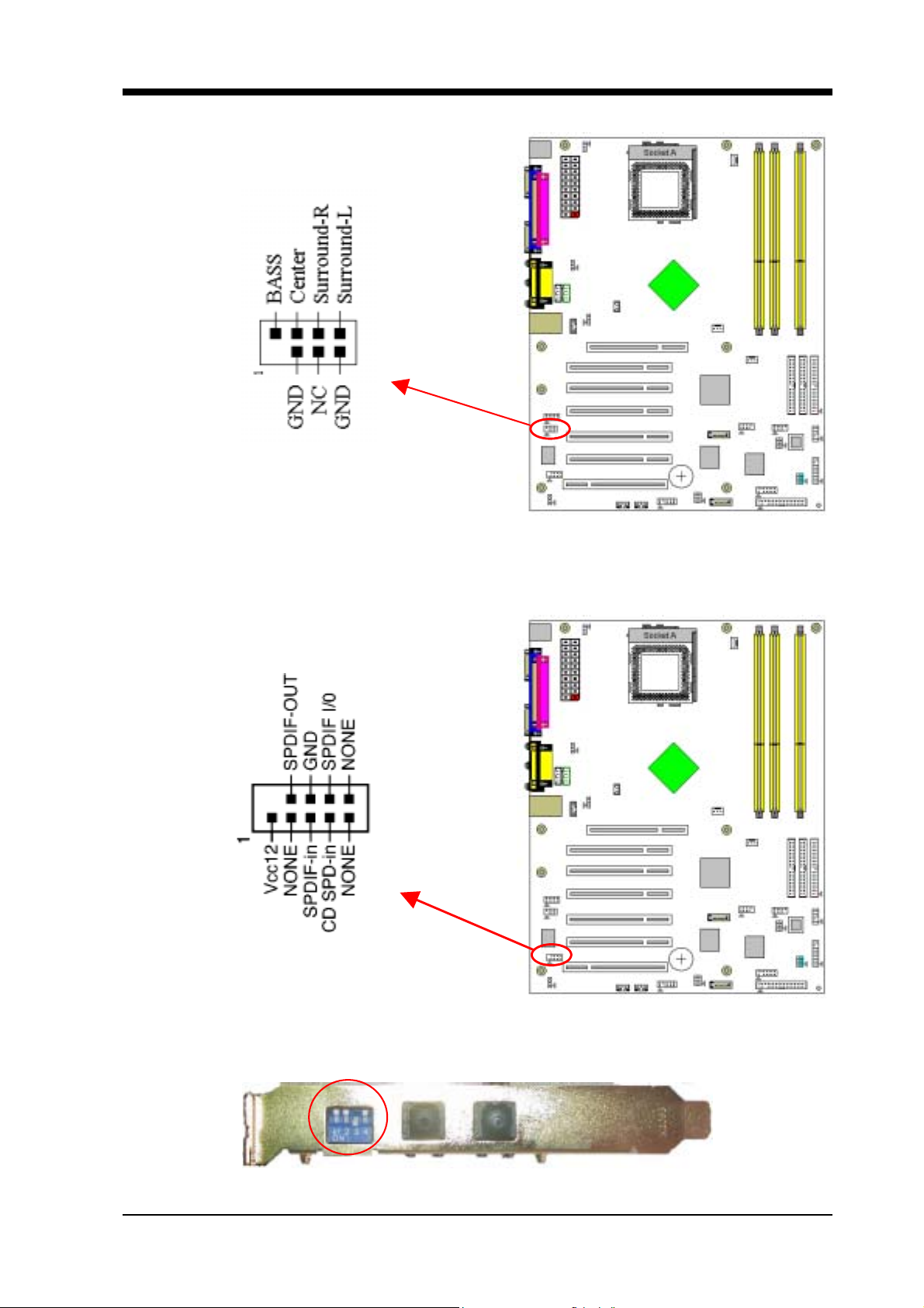
CN4B (AC3 Center / Surround + Bass Connector):
Chapter 2
This connector must be connected to a
CN4C (SPDIF Connector):
6-channel bracket
.
This connector must be connected to a SPDIF bracket.
The DIP switch of SPDIF bracket sets to: 1 OFF, 2 OFF, 3 ON, 4 OFF
7NJS Ultra User’s Guide 21

Chapter 2
JP6 (Power On By USB 0/1)
Pin Definition
1-2 Disable (default)
2-3 Enable
A USB keyboard hot key or a USB mouse click can turn on this board. You
must also set this jumper's cap to pins 2-3 to use this function.
JP6A & JP6B (Power On By USB 2/3 and 4/5):
Pin Definition
1-2 Disable (default)
2-3 Enable
JP6A USB 2/3
JP6B
USB 4/5
A USB keyboard hot key or a USB mouse click can turn on this board. You
must also set this jumper's cap to pins 2-3 to use this function.
22 7NJS Ultra User’s Guide

Chapter 2
CN23/CN23A (USB 2/3 and 4/5 Connectors):
If you want to use a USB Keyboard, you must enable the USB keyboard
support function in BIOS's Integrated Peripherals menu (See Section 3.4). This
board contains a USB Host controlle r and includes a root hub with two connector
for optional USB Adaptor (USB 2/3 and 4/5).
CN24 (CBOX 3 Front Panel Audio Connector):
This connector give you the option of a fr ont panel audio jack cable e xt. to be
plug into a special custom designed system case.
Simply remove the two jumper caps at pin [5-6] and [9-10] then plug it into the
(optional) cable ext. connector. Pin [5-6] and [9-10] are shorted (default) to
enable the back panel audio function.
7NJS Ultra User’s Guide 23

Chapter 2
CN25 (DigiDoc System Monitoring Display):
CBOX3 features CHAINTECH’s exclusive [DigiDoc], the most advance
system diagnostic monitoring display.
80-PORT diagnostic display during POST at system boot up!
CPU temperature monitoring, your system stays cool always!
DigiDoc is the doctor for your system!
Please refer to Appendix Digidoc 80-Port POST Error Code List.
FAN1/FAN2/FAN3 (CPU/System/Case Cooling Fan Connectors):
The board's management extension hardware is able to detect the CPU and
system fan speed in rpm (revolutions per m inute). The wiring and plug m ay vary
depending on the manufacturer. On standard fans, the red is positive (+12V), the
black is ground, and the yellow wire is the rotation signal.
24 7NJS Ultra User’s Guide

FAN4 (North Bridge Cooling Fan Power)
Chapter 2
The north bridge-cooling fan. The wiring and plug m ay va ry dependi ng on the
manufacturer. On standard fans, the red is positive (+
12V
), the black is ground.
JP5 (Power On By Keyboard):
Pin Definition
1-2 Disable (default)
2-3 Enable
This board can be turned on by the PS / 2 keyboard (hot key). To use this
function, select a hot key of your choice at the Hot Key Power ON option under
Wake Up Events in the BIOS's Power Management Setup screen. You must
also set this jumper's cap to pins [2-3] to use this function .
7NJS Ultra User’s Guide 25

Chapter 2
CN5 [WOL (Wake-on-LAN) Connector]:
Enable the Power ON by Ring/WOL selection in BIOS's Power Management
Setup Menu to use this funct i on. Thi s he ad er is used t o connect an add-in NIC
(Network Interface Card) which gives WOL capability to the motherboard .
CN5A [WOM (Wake-on-Modem) Connector]:
Enable the Power ON by Ring/WOL selection in BIOS's Power Management
Setup Menu to use this function. This header is used to connect an add-in
modem card which gives WOM capability to the motherboard.
26 7NJS Ultra User’s Guide

IR 2 (IR & CIR Connector):
Chapter 2
Select a UART Mode in BIOS's Integrated Peripherals menu the UART port
to support IR function. (See section
Peripherals
)
3.4
Super I/O Device of
Integrated
JP23 (Green Mode LED):
Pin Definition
1-2 CHAINTECH (default)
2-3 OEM
This cap is to setup Green LED flash mode. (Optional)
7NJS Ultra User’s Guide 27

Chapter 2
CN17 (Blue LED Connector):
These features work entirely the sam e as the power indic ator LED, both shows
the system’s power status. The only difference is that this one is blue while the
other is red LED.
CN9 (Chassis Open Alarm Connector):
This connector provides a buzzer sound when an attempt to open the chassis
occurs.
Note: Only certain chassis provides this function.
28 7NJS Ultra User’s Guide

CN7 (Smart Card Reader Connector):
Chapter 2
This connector must be connected to an optional Smart card reader.
7NJS Ultra User’s Guide 29

Chapter 2
2 . 6 1394 ACR Card
ACR CBOX-3
Connector
Regulations for standard PnP PCI2.1 and IEEE1394a interface.
The transmission speed so far for IEEE1394 is 100/ 200/ 400Mbps. In the
future the maximum transmission speed will reach 800Mbps or even 1Gbps.
IEEE1394 are user friendly, easy to use and it supports multi knots up to 63
knots and hot-swap.
To install the expansion card, remove the chassis cover and the bracket. Align
the card connector with the ACR slot and press firmly until the card is
completely seated on the slot. Secure the card to the chassis with the screw, and
put the chassis back on. Set up the BIOS according to section 3.4
CN1 CN4
30 7NJS Ultra User’s Guide

2.7 CBOX™ 3 Setup
1. Gently insert CBOX™ 3 into the regular 5-1/4” drive bay at the front
of system chassis and securely tighten the side screws.
2. Connect Motherboard to CBOX™ 3:
Function Motherboard CBOX™ 3
USB 2 & 3 CN23A CN1
USB 4 & 5 CN23 CN3
*Front Audio CN24 CN2
Chapter 2
IEEE 1394 1394 ACR card CN1
80 Port Display CN25 CN6
Wake On LAN CN5 CN7
* Remove CN24 Jumper Caps on motherboard 5-6, 9-10 before installation.
USB Cable (10 pin) x 2
Front Audio Cable (10 pin) x 1
IEEE-1394 Cable (8 pin) x 1
80 Port Display (10 pin) x 1
WOL Cable( 3 pin) x 1
CN4
JP6 (Power Select)
1-2 VCC5SBY (Default)
2-3 USB5V
Note:
Each cable got
7NJS Ultra User’s Guide 31
security-proof.

Chapter 2
2 . 8 Handigator: Function List
KEY
NO.
1 Turn on/Off PC 20 Volume Down
2 Open Browser 21 Mute
3 Open Email 22 Page Up
4 Search in WWW 23 Page Down
5 Previous page in WWW 24 Enter Key
6 Next Page in WWW 25 Tab Key
7 Stop browsing 26 Backspace Key
8 Refresh in WWW 27 7
9 Mouse 28 8
10 Mouse left button 29 9
11 Enter Key 30 4
12 Mouse right button 31 5
13 Previous Track 32 6
Function KEY
NO.
Function
14 Play/Pause Multimedia 33 1
15 Next Track 34 2
16 Fast Backward 35 3
17 Stop playing 36 0
18 Fast Forward 37 .(dot)
19 Volume Up 38 Esc Key
32 7NJS Ultra User’s Guide

Chapter 3
Chapter 3 BIOS Setup Program
Phoenix-Award BIOS ROM has a built-in setup program that allows users to
modify the basic system configuration. This information is stored in CMOS
RAM so that it can retain the setup information, even when the power is turned
off.
To enter the Phoenix-Award BIOS setup program press the [ Delete key ]
when you Power on or reboot the computer system. The primary screen as
shown in Figure 3-1 is a list of the menus and functions available in the setup
program. Select the desired i tem by y our arrow keys and press enter t o make the
changes. Operating commands are located at the bottom of this and all other
BIOS screens. When a field is highlighted, on-line help information is displayed
on the right side of the screen.
Figure 3-1
7NJS Ultra User’s Guide 33

Chapter 3
3 . 1 Standard CMOS Setup
The Standard CMOS Setup allows users to configure system components
such as hard disk drive, floppy disk drive and video display as well as date, time
and boot-up error signaling. This configuration menu should be changed when
installing a motherboard for the first time, changing hardware in your system
such as the HDD, FDD, video display, or when the CMOS data has been lost or
contaminated. Choose the St andard CMOS S etup option from the CMOS Setup
Utility menu (Figure 3-1) to display the following screen.
Figure 3-2
Date/Time:
Set the date and time of the system.
IDE (Primary/Secondary; Master/Slave):
This category identifies up to four IDE hard disk drives that have been install ed
in the computer. This section does not show information on other IDE devices
such as CD-ROM drives or other hard drive type such as SCSI drives.
Drive A:
Select different Floppy device Model. Available options are [None], [360K,
5-1/4 in], [1.2M, 5-1/4 in], [720k, 3-1/ 2 in], [1.44M, 3-1/2 in], and [2.88M, 3-1/2
in].
Video:
Select the type of video adapter present in your system. You can ignore this
setting if you are using a VGA monitor since VGA BIOS automatically
configures this setting.
34 7NJS Ultra User’s Guide

Chapter 3
Halt On:
When the system is powered on, BIOS performs a series of diagnostic tests
called POST (Power On Self Test). This function stops the computer if BIOS
detects a hardware e rror. You can tell BIOS to halt on all errors, no errors, or not
to halt on specific errors.
3.2 Advanced BIOS Features
By choosing the Advanced BIOS Features option from the CMOS Setup
Utility menu (Figure 3-1), the screen b elow is displayed. This sample screen
contains the manufacturer's default values for the motherboard.
Figure 3-3
(1) Virus Warning:
When you set as enabled, you receive a warning message if a program
(specifically, a virus) attempts to write to the boot secto r or the p artition table
of the hard disk drive.
NOTE:
Many disk diagnostic programs that access the boot sector table can trigger the
virus-warning message. If you plan to run such a program, we recommend that you first
disable the virus warning.
(2)
CPU Internal Cache/External Cache:
Cache memory is much faster than conventional DRAM system memory.
These fields allow you to e nable or disable the CPUs Level 1 buil t-in cache and
Level 2 external cache. Both settings are left enabled to significantly increase
the performance of your computer.
7NJS Ultra User’s Guide 35

Chapter 3
(3) Quick Power On Self Test (POST):
Enable this function to reduce the amount of time required to run the POST
(Power On Self Test). BIOS will save time by skipping some items during
POST. It is recom mended that you disable this se tting. Discove ring a problem
during boot up is better than loosing data during your work.
(4) First/Second/Third/Boot Other Device:
This option sets the sequence of drives BIOS attempts to boot from after
POST completes. BIOS will search these drives for an operating system.
(5) Boot Up Floppy Seek:
This is a set up check for floppy power-on after starting the computer
system.
(6)
Boot Up NumLock Status:
This function defines the keyboard's number pad as number keys or arrow
keys. If it is set at on the number keys will be activated, if it is set at off the
arrow keys will be activated.
(7) Gate A20 Option:
This allows you to set the Gate A20 status. When set to [Fast], Gate A20 is
cont rolled by chipset. When set to [Normal], Gate A20 is cont rolled by a
specific pin from the keyboard controller. Available options are [Fast] and
[Normal].
(8) Keyboard Interface:
Typematic Rate Setting
When enabled, you can set the following two-typematic control items.
When disabled, the keyboard controller determines keystrokes arbitrarily in
your system.
Typematic Rate (Chars/Sec)
The typematic rate sets the rate at which characters on the screen repeat
when a key is pressed and held down.
Typematic Delay (Msec)
The typematic delay sets how long after you press a key that a character
begins repeating.
(9) Security Option:
The Supervisor and/or User Password functions shown in Figure 3-1 must
be set to take advantage of this function. See Section 3.11 for password setting
information. When the Security Option is set to System, a password must be
entered to boot the system or enter the BIOS setup program. When the Security
Option is set to Setup, a password is required to enter the BIOS setup program.
(10) APIC Mode:
This item can enable or disable the APIC. (
Advanced Programmable
36 7NJS Ultra User’s Guide

Chapter 3
Interrupt Controller). Due to compliance to PC2001 design guide, the system
is able to run in APIC mode. Enabling APIC mode will exp and available IRQs
resources for the system. Available options are [Enabled] and [Disabled].
(11) MPS Version Control OS:
This item allows you to select which MPS (Multi-Processor Specification)
version to be used for the operating sys t e m. You need to select the MPS version
which is supported by your operating system. To find out which version to use,
consult the vendor of your operating system. Available options are [1.4] and
[1.1].
(12) OS Select For DRAM > 64MB:
If your system's DRAM is larger than 64MB and you are running OS/2,
select OS/2 as the item value. Otherwise, set the item value to No n-OS/2 for all
other operating systems.
(13) HDD Instant Recovery:
This board supports HDD Instant Recover, Select enable d to use the function.
Upon system boot up, the HDD Instant Recover Utility will be shown on the
screen. Select enable or disable to continue booting. A v ailable options are
Disabled
[
] and [
Enabled
].
(14) Small Logo(EPA) Show:
This setup allows photo that is EPA. Logo.
(15) Chassis Intrusion Warning:
Set to Enabled if you want the Chassis Intrusion Warning message during the
BIOS POST procedure. If your computer case has bee n opened, you should set
Disabled and restart. Then the warning message will be cleared.
7NJS Ultra User’s Guide 37

Chapter 3
3.3 Advanced Chipset Features
By choosing the [Advanced Chipset Features] option from the CMOS
Setup Utility menu (Figure 3-1), the screen below is displayed. This sample
screen contains the manufacturer's default values for the motherboard.
Figure 3-4 Advance Chipset Features
All of the above settings have been determined by the motherboard
manufacturer and should not be changed unless you are absolutely sure of what
you are doing. Explanation of the DRAM timing and chipset features setup is
lengthy, highly technical and beyond the scope of this manual. Below are some
abbreviated descriptions of the functions in this setup menu.
(1) System Performance:
Optimal: Select this option will let the system automatically detect its
performance.
Aggressive: Select this op tion for better system performance. It increases a
bit of the system performance.
Turbo: Select this option for a faster system performance. It will increase the
system performance, but it might result in an unstable system.
Expert: Select this option only if you are a professional user. This will allow
you to set the system performance according to your choice.
(2) FSB Frequency:
This feature allows the system and memory to run at FSB clock speed.
Options include 100 MHz (200 MHz) to 250 MHZ (500 MHz).
(3) CPU Ratio:
It is recommended to keep the default setting for stable system operation.
38 7NJS Ultra User’s Guide

Chapter 3
(4) CPU Interface:
Optimal: Select this option will let the system automatically detect its
performance.
Aggressive: Select this option for better system performance. It incr eases a
bit of the system performance.
(5) Memory Frequency:
By SPD: It automatically detects the memory frequency.
WARNING
Overclocking:
This motherboard is designed to support overclocking.
However, please make sure your components are able to
tolerate such abnormal setting, while doing overclocking.
Any attempt to operate beyond product specifications is
not recommended. We do not guarantee the dam ages or
risks caused by inadequate operation or beyond
product specifications
.
(6) Memory Timing:
The function allows you to enable or disable the DRAM timing by SPD.
When it is set to Manual, you can select the DRAM CAS Latency, DDR
SDRAM Cycle Length and Bank Interleave configuration.
(7) AGP Aperture Size (MB):
This function determines the amount of system memory that is given to the
AGP card. Options range from 32MB to 512MB. This is a dynamic memory
allotment in that the AGP card will only use the amount of memory that it
needs. The remaining memory, which is not in use, will be available fo r the
system. For example, if 16MB is allotted to the AGP card and the card only
needs 8MB, the remaining 8MB will be available for system use.
(8) AGP Frequency:
This function determines the amount of AGP frequency that is given to the
AGP card. Options range from
(66MHz)]
)
50 MHz
to
100 MHz
. (default [
Auto
(9) AGP 8X Support:
Enable this setting to utilize the 8X mode (twice as fast as 4X) offered by
advanced AGP cards. Your VGA card must support 8X mode in order to take
advantage of the faster speed.
(10) AGP Fast Write Capability:
Selecting [Enabled] to allow Fast Write Protocol for 8x/4x AGP to function.
Not all AGP cards support fast write.
PS:
(11) System BIOS Cacheable:
Enabling this function allows caching of the system BIOS ROM at
7NJS Ultra User’s Guide 39

Chapter 3
F0000h-FFFFFh, resulting in better system performance. However, if any
program writes to this memory area, a system error may result. Caching the
system BIOS results in better performance than shadowing the system BIOS.
(12) Video RAM Cacheable:
Enabling this function will allows caching of the video RAM, resulting in
better system performance. However, if any programs write to this memory
area, a system error may occur.
(13) Flash BIOS Protection:
The motherboard manufacturer developed BIOS protection technology that
protects the System BIOS from accidental corruption by unauthorized users or
computer viruses. When enabled, the BIOS data cannot be changed when
attempting to update BIOS with the FLASH utility. W hen disab led, the BIOS
data can be updated by using the FLASH utility.
3 . 4 Integrated Peripherals
This section provides information on setting per ipheral devices. By cho osing
the Integrated Peripherals option from the CMOS Setup Utility menu (Figure
3-1), the screen below is displayed. This sample screen contains the
manufacturer's default values for the motherboard.
Figure 3-5 Integrated Peripherals Screen
(1) IDE Function Setup:
Press [
advanced control:
40 7NJS Ultra User’s Guide
Enter
] to enter the sub-menu, which contain s the following items for

Chapter 3
OnChip IDE channel 0/1:
You can set this to disable the On Chip IDE controller if you are going to
add a higher performance IDE board.
IDE Primary/Secondary Master/Slave PIO:
The four IDE PIO (programmed Input/Output) fields let you set a PIO
mode (0-4) for each IDE device that the internal PCI IDE interface supports.
Modes 0 through 4 provide successively increased performance. Set to Auto
mode, the system automatically determines the best mode for each device.
IDE Primary/Secondary Master/Slave UDMA:
Ultra DMA implementation is possible only if your IDE device supports it
and your operating environment contains a DMA driver. If both your hard
drive and software support Ultra DMA, select [Auto] to enable BIOS
support.
IDE Pre-fetch Mode:
The onboard IDE drive interfaces support prefetching for faster drive
accesses. Set to [Disabled] if this primary or secondary
IDE HDD Block Mode:
Block mode is also called block transfer, multiple commands, or multiple
sector read/write. If your IDE hard drive supports block m ode, select Enabled
to auto-detect the optimal number of block read/writes per sector the drive
can support.
(2) Onboard Device:
This section provides information for setting onboa rd device. By choosing
the Integrated Peripherals option fr om the CMOS Setup Utility menu (Figure
3-5), the screen below is displayed. This sample screen contains the
manufacturer's default values for the motherboard.
Press [Enter] to enter the sub-menu, which contains the following items for
advanced control:
AC97 Audio:
This feature allows you to enable/disable the on-board AC97 audio
function.
MC97 Modem:
This item allows you to enable/disable the MCP-T chipset’s feature to
support MC97 Modem.
CMedia Audio:
This feature allows user to select 6 channels function, if that connect one
6ch Expansion kit to motherboard.
MAC LAN (nVIDIA):
This item allows you to Auto / Disabled the onboard LAN function.
7NJS Ultra User’s Guide 41

Chapter 3
Promise RAID:
This item allows you to Enabled / Disabled the onboard Promise RAID
function.
(3) Super IO Device:
This section provides information on setting Super I/O device. By choosing
the Integrated Peripherals option from the CMOS Setup Utility menu (Figure
3-5), the screen below is displayed. This sample screen contains the
manufacturer's default values for the motherboard.
Press [Enter] to enter the sub-menu, which contains the following items for
advanced control:
Onboard FDC Controller:
Select Enabled if your system has a floppy disk controller (FDC) installed
on the system board and you wi sh to use it. If you install an add-in FDC or the
system has no floppy drive, select Disabled in this field.
Onboard Serial Port 1/2:
Select an address and corresponding i nterrupt for the first and second serial
ports. Available options are [3F8/IRQ4], [2E8/IRQ3], [3E8/IRQ4],
[2F8/IRQ3], [Disabled], and [Auto].
UART Mode Select:
This function allows you to select an operating mode for the second serial
port. (Normal RS-232C serial port / IRDA / SCR / ASKIR 0.57-MB/sec
infrared port)
Onboard Parallel Port:
Select a logical LPT port address and corresponding interrupt for the
physical parallel port.
Parallel Port Mode:
Select an operating m ode for the onboard paral lel (pri nter) port. Sele ct SPP
unless you are certain your hardware and software support one of the other
available modes.
ECP Mode Use DMA:
This item automatically specifies a DMA channel 1 or 3 for the parallel port
when it is set to [ECP] or [ECP+EPP] mode.
Game Port Address:
This item disables or assigns the address of the Game port. Available
options are [201] and [209].
Midi Port Address:
This item disables or assigns the address of the Midi port. Available options
are [300] and [330].
42 7NJS Ultra User’s Guide

Chapter 3
Midi Port IRQ:
This item specifies an IRQ for the Midi port.
(4) Init Display First:
This function allows user to choose between [Onboard / AGP] or [PCI
Slot] to initialize Display first.
(5) OnChip USB:
Enable the on-board Universal Serial Bus (USB V1.1 or V2.0) controller if
you want to connect a USB device to your system. Note that if this setting is
disabled, you can still temporarily use a USB ke yboard du ring bo ot up so that
you can enter BIOS and enable this setting. If you pass the boot up stage
without enabling this function, your PS/2 keyboard will no longer work.
Available options are [Disabled], [V1.1+V2.0], and [V1.1].
(6) USB Keyboard Support:
Select Enabled if your system has a USB keyboard installed on the system
board. If your system has no USB keyboard, select Disabled in this field.
(7) On Chip 1394:
Select [
board
Auto
] if your system has an IEEE 1394 device installed on the system
3.5 Power Management Setup
This section provides information on the Green PC power management
functions. By choosing the Power Management Setup option from the CMOS
Setup Utility menu (Figure 3-1), the screen below is displayed. This sample
screen contains the manufacturer's default values for the motherboard
Figure 3-6 Power Management Setup
7NJS Ultra User’s Guide 43

Chapter 3
(1) ACPI Suspend Type:
This item specifies the power saving modes for ACPI function. Available
options are:
S1 (POS):
The S1 state is low power state. In this state, no system context (CPU or
Chipset) is lost and the hardware maintains all system contexts.
S3 (STR):
The S3 state is a lower power state, where the information of system
configuration and opened applica tions / files are saved to ma in memory.
The remaining power of other hardware components are turn off to save
energy.
The information stored in memory will be used to restore the system when a
[wake up] event occurs.
S1 & S3
If S3 state is supported by the system, by default [S3] is automatically
selected. Otherwise [S1] is selected.
(2) Power Management:
Power management allows the computer to save electricity when it is not in
use by entering increasingly deep power saving modes.
(3) Video Off Method:
This function serves as both a screen saver and power saver for monitors.
See the next function, Video Off After, for setting the video timer.
Blank Screen - BIOS will only blank the monitor's screen. The electricity
saved in this mode is negligible and this function is only used as a screen saver
to prevent screen damage while the screen is on but not in use.
V/H SYNC+Blank - The system turns off the vertical and horizontal
synchronization ports, writes blanks to the VGA buffer and the monitor's
electron gun turns off. This function requires a monitor with Green features in
order to take advantage of the power saving function. If you enable this funct ion
and do not have a Green monitor, the result will be the same as if you had
selected Blank. This function serves as both a screen saver and a power saver.
DPMS Support - Select this option if your video card supports the Display
Power Management Signaling (DPMS) standard (i.e., you have a monitor that
supports Green features). Use software supplied by your video subsystem to
set video power management options.
(4) HDD Power Down:
Shuts down any IDE hard disk drives in the system after a period of inactivity
as set in this user configurable field. This feature does not affect SCSI hard
drives.
44 7NJS Ultra User’s Guide

Chapter 3
(5) HDD Down In Suspend:
In Suspend any IDE hard disk drives in the system after a period of inactivity
as set in this user configurable field. This feature does not affect SCSI hard
drives.
(6)
Soft-Off by PBTN:
When set to Delay 4 Sec., this fun ction allows the power button to put the
system in Suspend, a power saving m ode. When set to Instant-Off the Soft-Off
by PWR-BTN function is disabl ed and the computer turns c ompletely off when
the power button is pressed.
(7) PWRON After PWR-Fail:
This allows you to set whether you want your system to reboot after the
power has been interrupted. [Off] leaves your system off and [On] reboots
your system. [Former-Sts] sets your system back to the state it is before the
power interruption.
Configuration option: [Off], [On], [Former-Sts]
(8) Wake up Events
Power On by PME/Onboard LAN:
When enabled, the nVidia LAN, which is on Board, will be able to receive
a signal and wake up the system from soft off and suspend mode . You should
connect the LAN to the RJ45 port and turn on the resume event in suspen d
mode.
Power On by Ring/WOL:
When enabled, a Mod em/LAN Card (PCI Card or Ext. Modem) will be
able to receive a signal and wake up the syst em from soft off and green mode.
You should connect the modem to the COM port and call your PC to power
on.
USB Resume from S3:
Allows the activity of USB device to wake up the system from S3 power
saving modes. Settings are [Enabled] and [Disabled].
Power-On by Alarm:
When enabled, this setting allows the system to turn back on at a designated
time of the month. User must designate date of month and time of day.
This function is only available when using an ATX power supply and the
Software Power-Off function to turn off the computer.
POWER ON Function:
This control show the PS/2 mouse or keyboard can power on the system.
Available settings are [Password], [Hot KEY], [Mouse Move], [Mouse
Click], [Any KEY], [BUTTON ONLY] and [Keyboard 98].
7NJS Ultra User’s Guide 45

Chapter 3
KB Power ON Password:
If POWER ON Function is set to [Password], then you can set a password
in the field for the PS/2 keyboard to power on the system.
Hot Key Power ON:
If POWER ON Function is set to [Hot KEY], you can assign a hot key
combination in the field for the PS/2 keyb oard to power on the system.
Settings: [Ctrl-F1] through [Ctrl-F12].
3.6 PNP/PCI Configurations
This section provides IRQ and DMA setting information. By choosing the
PNP/PCI Configuration option from the CMOS Setup Utility menu (Figure 3-1),
the screen below is displayed. This screen contains the manufacturer's default
values for the motherboard.
Figure 3-7 PNP/PCI Configurations
Reset Configuration Data:
If you want to reset CMOS IRQ divide hardware device, please selected to
[Enabled].
Resources Controlled By:
When set to Manual the system BIOS will no t refer to the ESCD for IRQ &
DMA information. Instead, it will refer to the items in the setup menu for
assigning IRQ & DMA. When set to Auto the system BIOS will refer to the
ESCD for all legacy information.
ESCD (Extended System Configuration Data) provides a detailed format of
the configuration data structures stored in flash memory. Each data structure
46 7NJS Ultra User’s Guide

Chapter 3
defines the resources used by a device or a card in the system. This includes
legacy and PCI/ISA PnP devices.
PCI/VGA Palette Snoop:
When set to [Enabled], multiple VGA devices operating on different buses can
handle data from the C PU on ea ch set of pa le t t e re gi st ers on ever y video de vi ce.
Bit 5 of the command register in the PCI device configuration space is the VGA
Palette Snoop bit (0 is disabled). Available options are [Enabled] and
[Disabled].
Slot 1,5/2/3/4 Use IRQ No:
These Field automatically assign the IRQ for each PCI slot. The default set ting
for each field is [Auto], which utilizes auto-routing to determine IRQ
assignments. Configuration IR Q option: [Auto], [3], [4], [5], [7], [9], [10], [11],
[12], [14] and [15].
FDD IRQ Can Be Free:
This function allows user to choose if the FDD IRQ can be freed up. The
default setting is Yes and this do es n ot allow the IRQ to be free.
7NJS Ultra User’s Guide 47

Chapter 3
3.7 PC Health Status
By choosing the PC Health Status option from the CMOS Setup Utility menu
(Figure 3-1), the screen below is displayed. This field shows you the current
system temperature/external voltages input and the current CPU FAN and
System FAN operating speed.
Figure 3-8 PC Health Status
Shutdown Temperature:
This item allows you to set the shutdown temperature level for the processor.
When the processor reaches the temperature you set, this will shutdown the
system. This function only works in ACPI-aware OS (such as Windows 98 / ME
/ 2000).
Available options are [
100°C/210°F
[
].
85°C/185°F
90°C/194°F
], [
95°C/203°F
], [
], and
48 7NJS Ultra User’s Guide

Chapter 3
3.8 Frequency/Voltage Control
By choosing the Frequency/Voltage Control option from the CMOS Setup
Utility menu (Figure 3-1), the screen below is displayed. This sample screen
contains the manufacturer's default values for the motherboard.
Figure 3-9 Frequency/Voltage Control
FSB/AGP Spread Regulator:
This item is used to enable or disable the clock generator’s Spread Spectrum
feature. When over clocking the processor, always set it to Disabled. Setting
options: [
DIMM Voltage Regulator:
This feature allows the system memory to run at Power ON of Voltage.
AGP Voltage Regulator:
This feature allows the AGP bus to working of Voltage.
CPU Voltage Regulator:
This feature allows the CPU to working of Voltage. Available options are
1.400V
[
0.5%
] to [
WARNING
1.00%
], [
2.150V
], and [
].
Overclocking
This motherboard is designed to support
overclocking. However, please make sure your
components are able to tolerate such abnormal
setting, while doing overclocking. Any attempt to
operate beyond product specifications is not
recommended.
or risks caused by inadequate operation or beyond
product specifications.
Disabled
We do not guarantee the damages
]
7NJS Ultra User’s Guide 49

Chapter 3
3.9 Load Fail-Safe Defaults
Load Fail-Safe Defaults loads the default BIOS values directly from the
CMOS Setup Utility menu (Figure3-1). If the stored record created by the
setup program becomes corrupted and therefore unusab le, these defaults will
be loaded automatically when you turn on the computer.
3.10 Load Optimized Defaults
Load Optimized Defaults loads the default system values directly fr om the
CMOS Setup Utility menu (Figure3-1). If the stored record created by the
setup program becomes corrupted and therefore unusable, these defaults will
be loaded automatically when you turn on the computer.
3 . 1 1 Set Supervisor Password & User Password Setting
There are four different variables that control password settings. The first
two are located under the Security Option function in BIOS Features Setup
Menu (Figure 3-1). When the Security Option function is set to Setup, a
password is required to enter BIOS and change BIOS settings. When the
Security Option function is set to
BIOS and the computer's operating system (for example Windows 98) found
on the boot drive.
The third and fourth variables are user password and supervisor password
selected in BIOS (Figure 3-1). The main purpose of separating user and
supervisor is to allow only the superviso r to have control over the settin gs in
BIOS. The user, on the other hand, is only allowed to access the computer's
operating system and change the user password in BIOS.
System
, a password is required to enter both
Note:
50 7NJS Ultra User’s Guide
that when there is no supervisor password set, the user password controls
access to all BIOS settings.

Chapter 3
3.12 Save and Exit Setup
If you select this and type [Y] (for Yes) followed by the [Enter] key, the
values entered in the setup u tilities will be recorded in the CMOS memory of
the BIOS chip.
3.13 Exit Without Saving
Selecting this option and pressi ng Y followed by the [Enter] key lets you exit
the Setup program without recording any new values or changing old ones.
7NJS Ultra User’s Guide 51

Chapter 4
C h a p t e r 4 DRIVER Setup
Insert the support CD that come with your motherboard into your
CD-ROM drive or double-click the CD drive icon in [
computer
] to enter the setup screen.
My
4.1 Nvidia Driver Package Setup
1.Select [Nvidia Driver Package]
2.Select [Next >]
52
7NJS Ultra User’s Guide
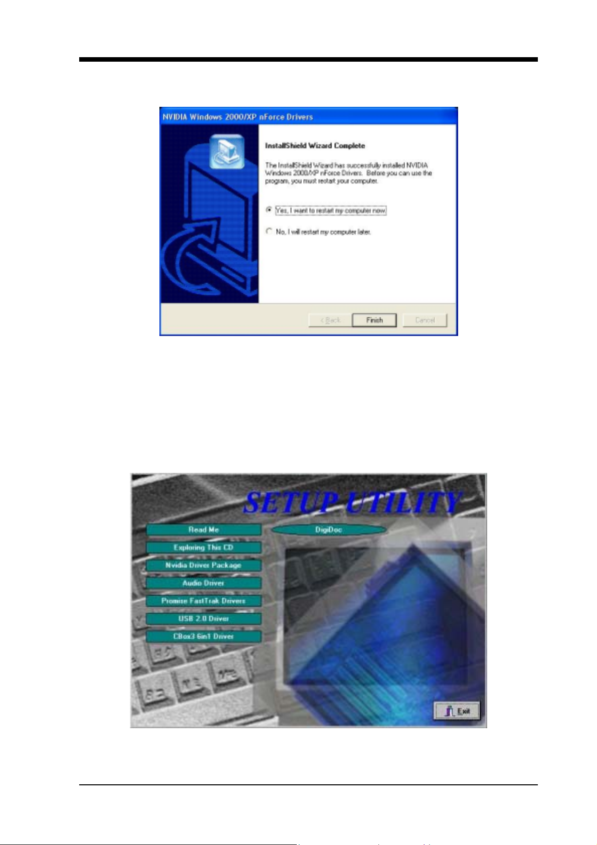
Chapter 4
3.Please select [Yes] to restart computer now or [No] to restart later, and
then click on [Finish] to complete the installation.
4.2 C-MEDIA Sound Driver Setup
This section provides information on installed audio devices by
choosing [
1.Select [Nvidia Driver Package]
Audio Drivers
] from the Setup Driver menu.
7NJS Ultra User’s Guide 53

Chapter 4
2.Select [Audio Drivers] to begin software installation
3. Select [Install Device Driver and Applications]
54
7NJS Ultra User’s Guide

4. Select the setup language and click [OK] to continue.
5. Select [Next] to proceed
Chapter 4
6. Please select a folder where the program will be installed and click
[Next >] to proceed.
7NJS Ultra User’s Guide 55

Chapter 4
7. Please select one folder from existing list of folders and click
[Next >] to proceed.
8. Select [Continue Anyway] to proceed.
56
7NJS Ultra User’s Guide

Chapter 4
9. Please select [Yes] to restart com puter now or [ No] to restart later, and
then click [OK] to complete the installation.
4.3 Promise FastTrak Driver setup
This section provides information on installing Serial ATA
drivers by choosing [
Promise FastTrak Driver
] from the Setup
Driver menu. The installation process is only available when Serial
ATA is installed.
7NJS Ultra User’s Guide 57

Chapter 4
Installing Serial ATA from Windows
unction:
f
Add New Hardware
1. Close any running applications.
2. Open [My Computer].
3. Double click on the [Control Panel] icon.
4. Double click on the [Add New Hardware] icon.
5. Click on the [Next] button.
6. A window will ask: [Do you want Windows to search for new
hardware?], select [No] then click on the [Next] button.
7. Various device types will be listed. Select [SCSI controllers]
and press [Next].
8. Insert the driver installation diskette into CD-ROM, and then
click on the [Have Disk...] button.
9. Select CDROM:\Promise\FastTrak376\O.S.
10. Click on the [OK] button.
11. Click on the [Next] button.
12. If you see a window that displays the settings (resources) to be
used by the driver, click on [Next] again. Windows will then
install the driver.
13. Click o n the [Finish] button.
14. The system will then ask you to restart the system.
NOTE: The driver for ACPI function is useful only if hardware
supports ACPI function.
58
7NJS Ultra User’s Guide

Chapter 4
4.4 USB 2.0 Driver Setup
This section provides information on installing USB devices by
choosing [
1.Select [USB 2.0 Driver]
USB 2.0 Driver
] from the Setup Driver menu.
2.Please select [Yes] to restart computer now or [No] to restart later, and
then click [Close] to complete the installation.
7NJS Ultra User’s Guide 59

Chapter 4
4.5 CBOX3 6in1 Driver setup
This section provides information on installing USB devices by
choosing [
CBox3 6in1 Driver
1. Select [CBox3 6in1 Driver]
] from the Setup Driver menu.
2. Select [Next >] to begin the installation process.
60
7NJS Ultra User’s Guide

3. Select the type of installations and click [Next] to continue.
Chapter 4
4. Select [Next >] to continue.
7NJS Ultra User’s Guide 61

Chapter 4
5.Please select a folder where the program will be installed and click on
[Next >] to proceed.
6.Select [Next >] to proceed.
62
7NJS Ultra User’s Guide

Chapter 4
7.
Please select [Yes] to restart computer now and then click [Finish] to
complete the installation.
4 . 6 DigiDoc Setup
This section provides information on installing USB devices by
choosing [
1.Select [DigiDoc]
DigiDoc
] from the Setup Driver menu.
7NJS Ultra User’s Guide 63

Chapter 4
2.Click [Next >] to continue.
3.Please select a folder where the program will be installed and click
[Next >] to proceed.
64
7NJS Ultra User’s Guide

4.Select the type of installations and click [Next] to continue.
Chapter 4
5.Please select one folder from existing list of folders and click on
[Next >] to proceed.
7NJS Ultra User’s Guide 65

Chapter 4
6. Select [Next >] to proceed.
7. Please select [Yes] to restart computer now or [No] to restart later, and
then click [Finish] to complete the installation.
66
7NJS Ultra User’s Guide

8.Select [Finish] to complete the installation.
Chapter 4
7NJS Ultra User’s Guide 67

Chapter 5
C h a p t e r 5 Audio Device Application
This sound card supports Windows 95/98/M E / NT4.0/2000 ope rat i ng systems.
To start the Audio Application Program simply select the [Start]→[Program
Files]→[PCI Audio Applications]→[Audio Rack]
It includes the following options :
(1) Audio Rack:
Which includes Audio Rack, CD Player, MIDI Player, Mixer and MP3
Player.
(2) Multi-Channel Audio Demo:
(Does not support Windows NT4.0)
A demonstration for the Multi-Chan nel Audio.
(3) Uninstall Applications:
Which uninstalls the driver and all application programs for the Sound
card.
5 . 1 Audio Rack
Audio Rack includes 4 control panels:
C-Media Mixer Volume
CD Player
MIDI Player
MP3 WAVE Player
You can start the Audio Rack by selecti ng 【Start】→【Program】→【PCI Audio
Applications】→【Audio Rack】
CD Player Output
Configuration
MIDI Player Output
Configuration
MP3 WAVE Player
Configuration
68
Mixer Setup
7NJS Ultra User’s Guide

1. C-Media M i x e r Volume
A. Volume Control
Chapter5
You can simply double click the icon
located at button right corner of
Windows to open the C-Media Mixer volume control.
This control panel includes Master Volume, CD Audio, Microphone,
WAVE, SW Synth, A/V (AUX) In, MONO IN, and LINE IN.
B. Mixer Recording Control
This control panel includes CD Audio, Microphone, WAVE, Stereo Mix,
A/V(AUX IN), and LINE IN.
C. [ Help ]
7NJS Ultra User’s Guide 69

Chapter 5
D.
(1) SPDIF:
•
Output:
Mixer Advance Setting:
S/PDIF Playback:
To activate SPDIF OUT. (SPDIF Out only on earphone and 2
speakers.)
Sampling Rate:
Transfer the Wave file from t he computer t hrough optical fiber
out to any digital media devices, ex. MD or DAT Advanced
media devices. (SPDIF-out only supports 44.1KHz and 48KHz
High frequency rates.)
70
• Input:
Loop back (to digital out):
Transfer the Wave file from t he computer t hrough optical fiber
out to any digital media devices, ex. MD or DAT Advanced
media devices. (SPDIF-out only supports 44.1KHz and 48KHz
High frequency rates.)
Monitoring (to analog out):
Monitors the SPDIF IN signal (Digital S PDIF signals use the
analog output through LINE OUT to make sound.)
Validity Detection:
Select this option to detect and check the validity of the f iber
signal.
7NJS Ultra User’s Guide

Format:
Select between Normal and Reverse.
Chapter5
Device:
For device feature select between S/PDIF #1 and S/PDIF #2.
• Copyright Protection:
Audio files have copyrights. Please select this option to prevent
(2) Speakers:
•
Headset & 2 channel speaker setup
•
4 channel speaker setup
•
6 channel speaker setup
7NJS Ultra User’s Guide 71
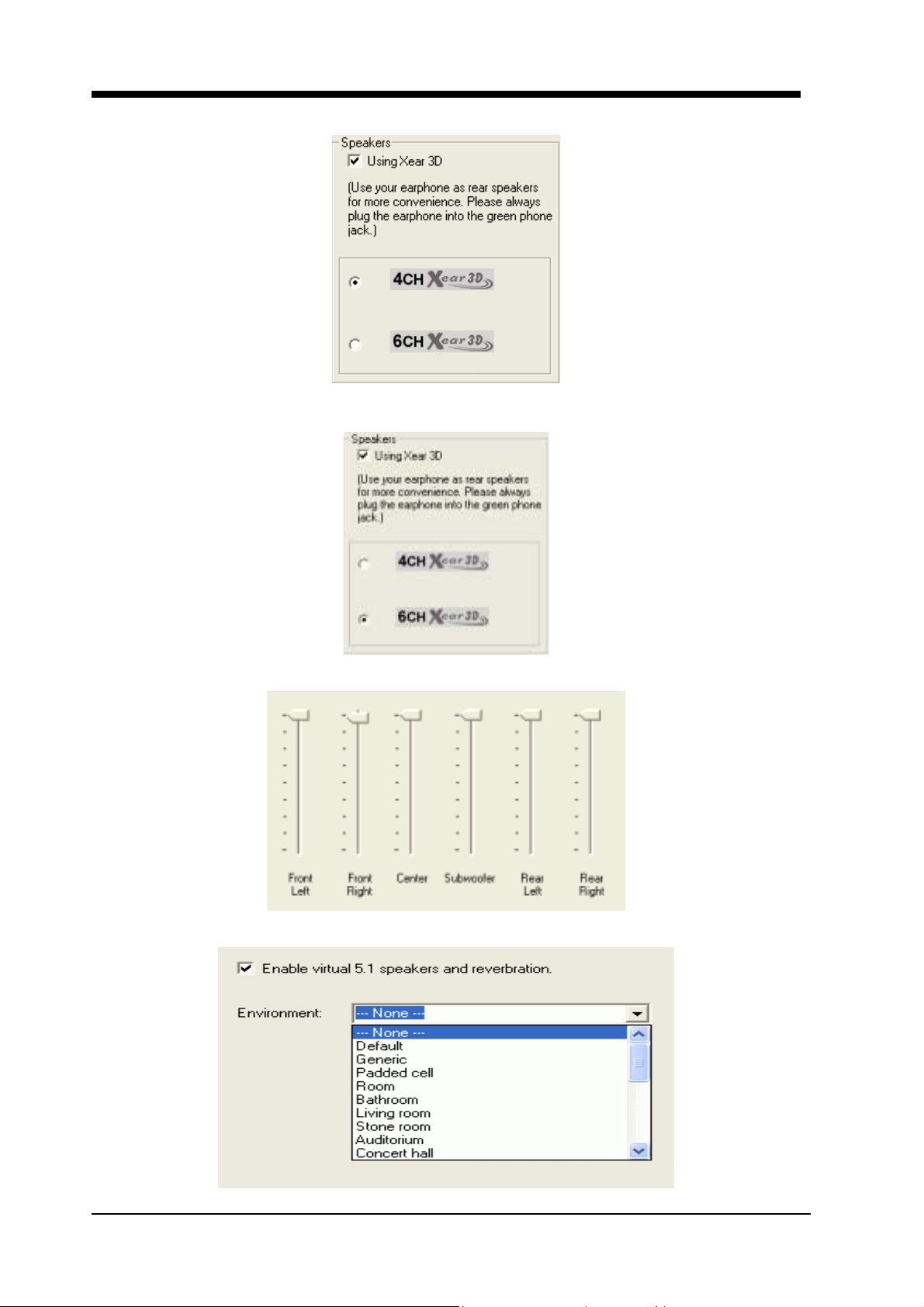
Chapter 5
• User 4ch XeaR mode setup
• User 6ch XeaR mode setup
(3) Volume:
(4) Sound Effect:
72
7NJS Ultra User’s Guide

(5) Option:
【Enable Hot-Key Setting】
This provides settings for Hot-Keys for Volume control, Mute, and
Display.
【Enable Microphone Booster】
Chapter5
Enable the microphone’s electrical circuit to increases the sensitiv ity
of the microphone. When designing the audio chip, it limits the type of
microphones that are available. The audio chip only supports Active or
Capacitive types of Microphone. These microphones are those standard
microphones we get on the market, or t hose earphones that come wit h a
microphone. The one that Karaoke uses does not work on this chip.
【Load Mixer Defaults】
This loads the original factory setting for the Sound Effects. (It
restores Volume, Wave, and MIDI.)
2. CD Player Output Configuration:
Setup:
(1) Enable to choose the Audio CD drive of your system.
(2) Enable to activate SPDIF signal output (only supports optical fiber
under Windows 95/98).
7NJS Ultra User’s Guide 73

Chapter 5
[Help]
3. MIDI Player Output Configuration:
Setup:
A. Under Win 95 / 98
3 options availabl e for Output device: [Defaul t MidiOut Device], [Rol and
MPU-401], [Microsoft GS Wavetable SW Synth].
B. Under Windows NT4.0
Only CMPCI MIDI device is available.
C. Under Windows 2000 / ME / XP
3 options available for Output device: [Default MidiOut Device],
[Microsoft GS Wavetable SW Synth], [Roland MPU-401]
74
7NJS Ultra User’s Guide

[Help] :
Chapter5
4. MP3 WAVE Pl ayer Configuration:
Sound Effecter Setting Button:
(1) Reverberation:
This is to setup the depth of the sound environment.
(2) Equalizer:
This is to setup the high and low pitch of the sound frequency output.
(3) Surround:
This is for setting up speaker output mode.
(4) Playback Mode
To select the music playback mode provided.
7NJS Ultra User’s Guide 75

Chapter 5
Configuration :
Playback:
Playback delay time for Mini-Disk recording. Please use default setting.
Recording Configuration:
Recording Format :
Quality:
(1) Name:
This is to setup the recording format. There are 3 selections: CD Quality,
Radio Quality, and Telephone Quality. The default setting is CD Quality.
(2) Format:
Only PCM format is available while recording with audio card.
(3) Attributes:
Enabling to setup recording quality. The default is set at 44.100 kHz
16Bit Stereo 172 kb/sec
(4) File Name:
Enable to setup the recording source. Type in the file name you plan to
record or click on the [BROWSE] icon and select the desired file save
destination.
[Help] :
76
7NJS Ultra User’s Guide

Chapter5
5 . 2 Multi- Channel Demo
[ STAR ] → [ Program ] → [ PCI Audio Applications ] →
[ Multi-Channel Demo ]
Click on the wide-screen TV in the center to get into [Advance] screen
1. Set speaker function for demo mode:
2. Set EAX function for demo mode:
In Advance mode, here you can configure according to your system
hardware or personal preference.
7NJS Ultra User’s Guide 77

Chapter 6
Chapter 6 DigiDoc
CBOX3 features CHAINTECH’s exclusive “DigiDoc”, the most advance
system diagnostic monitoring display.
80-PORT diagnostic display during POST at system boot up!
CPU temperature monitoring, your system stays cool always!
DigiDoc is THE doctor for your system!
78
7NJS Ultra User’s Guide

Digidoc 80-Port POST Error Code List
Appendix
Digidoc 80-Port POST Error Code List
POST (hex) Description
CF
C0
C1
C3
C5
01
03
Test CMOS R/W functionality.
Early chipset initialization:
-Disable shadow RAM
-Disable L2 cache (socket 7 or below)
-Program basic chipset registers.
Detect memory:
-Auto-detection of DRAM size, type and ECC.
-Auto-detection of L2 cache (socket 7 or below)
Expand compressed BIOS code to DRAM.
Call chipset hook to copy BIOS back to E000 & F000
shadow RAM.
Expand the Xgroup codes locating in physical address
1000:0
Initial Superio_Early_Init switch.
05
07
08
0A
0E
10
12
1.Blank out screen.
2.Clear CMOS error flag.
1. Clear 8042 interface.
2. Initialize 8042 self-test.
1. Test special keyboard controller for Winbond 977 series
Super I/O chips.
2. Enable keyboard interface.
1. Disable PS/2 mouse interface (optional).
2. Auto detects ports for keyboard & mouse followed by a
port & interface swap (optional).
3. Reset keyboard for Winbond 977 series Super I/O chips.
Test F000h segment shadow to see whether it is R/W-able
or not. If test fails, keep beeping the speaker.
Auto detect flash type to load appropriate flash R/W codes
into the run time area in F000 for ESCD & DMI support.
Use walking 1’s algorithm to check out interface in CMOS
circuitry. Also set real-time clock power status, and then
check for override.
79

Digidoc 80-Port POST Error Code List
POST (hex) Description
14
16
18
1B
1D
1F
21
23
Program chipset default values into chipset. Chipset
default values are MODBINab le by OEM customers.
Initial Early_Init_Onboard_Generator switch.
Detect CPU information including brand, SMI type (Cyrix
or Intel) and CPU level (586 or 686).
Initial interrupts vector table. If no special specified, all
H/W interrupts are directed to SPURIOUS_INT_HDLR &
S/W interrupts to SPURIOUS_soft_HDLR.
Initial EARLY_PM_INIT switch.
Load keyboard matrix (notebook platform).
HPM initialization (notebook platform)
1. Check validity of RTC value: e.g. a value of 5Ah is an
invalid value for RTC minute.
2. Load CMOS settings into BIOS stack. If CMOS
checksum fails, use default value instead.
3. Prepare BIOS resource ma p for PCI & PnP use. If ESCD
is valid, take into consider atio n of the ESCD’s legacy
information.
4. Onboard clock generator initialization. Disable
respective clock resource to empty PCI & DIMM
slots.
5. Early PCI initialization:
- Enumerate PCI bus number.
- Assign memory & I/O resource.
- Search for a valid VGA device & VGA BIOS, and put
it into C000:0.
80
27
Initialize INT 09 buffer.
1. Program CPU internal MTRR (P6 & PII) for 0-640K
memory address.
2. Initialize the APIC for Pentium class CPU.
29
3. Program early chipset according to CMOS setup.
Example: onboard IDE controller.
4. Measure CPU speed.
5. Invoke video BIOS.

Digidoc 80-Port POST Error Code List
POST (hex) Description
1. Initialize multi-language.
2D
2. Put information on screen display, including Award title,
CPU type, and CPU speed.
33
3C
3E
40
43
47
49
4E
Reset keyboard except Winbond 977 series Super I/O
chips.
Test 8254
Test 8259 interrupt mask bits for channel 1.
Test 8259 interrupt mask bits for channel 2.
Test 8259 functionality.
Initialize EISA slot
1. Calculate total memory by testing the last double word
of each 64K page.
2. Program writes allocation for AMD K5 CPU.
1. Program MTRR of M1 CPU
2. Initialize L2 cache for P6 class CPU & program CPU
with proper cacheable range.
3. Initialize the APIC for P6 class CPU.
4. On MP platform, adjust the cacheable range to smaller
one in case the cacheable ranges between each CPU are
not identical.
50
52
55
Initialize USB
Test all memory (clear all extended memory to 0)
Display number of processors (multi-processor platform)
1. Display PnP logo.
57
2. Early ISA PnP initialization
- Assign CSN to every ISA PnP device.
59
5B
Initialize the combined Trend Anti-Virus code.
(Optional Feature) Show message for entering AwdFlash.EXE
from FDD (optional)
1. Initialize Init_Onb o a rd _Su per_ I O switch.
5D
2. Initialize Init_Onbaord_AUDIO switch.
81

Digidoc 80-Port POST Error Code List
POST (hex) Description
60
65
67
69
6B
6D
6F
73
Okay to enter Setup utility; i.e. not u ntil this POST stage
can users enter the CMOS setup utility.
Initialize PS/2 Mouse
Prepare memory size information for function call: INT
15h ax=E820h
Turn on L2 cache
Program chipset registers according to items described in
Setup & Auto-configuration table.
1. Assign resources to all ISA PnP devices.
2. Auto assign ports to onboard COM ports if the
corresponding item in Setup is set to “AUTO”.
1. Initialize floppy controller.
2. Set up floppy related fields in 40:hardware.
(Optional Feature) Enter AWDFLASH .EXE if:
- AwdFlash is found in floppy drive.
- ALT+F2 is pressed.
75
Detect & install all IDE devices: HDD, LS120, ZIP,
CDROM
77
7A
Detect serial ports & parallel ports.
Detect & install co-processor
1. Switch back to text mode if full screen logo is supported
- If errors occur, report errors & wait for keys.
7F
- If no errors occur or F1 key is pressed to continue:
w/Clear EPA or customization logo.
1. Call chipset power management hook.
2. Recover the text fond used by EPA logo (not for full
82
screen logo)
3. If password is set, ask for password.
83
84
Save all data in stack back to CMOS
Initialize ISA PnP boot devices.
82

Digidoc 80-Port POST Error Code List
POST (hex) Description
1. USB final Initialization.
2. NET PC: Build SYSID structure.
3. Switch screen back to text mode
4. Set up ACPI table at top of memory.
85
5. Invoke ISA adapter ROMs.
6. Assign IRQs to PCI devices
7. Initialize APM
8. Clear noise of IRQs.
93
94
95
96
FF
Read HDD boot sector information for Trend Anti-Virus
code
1. Enable L2 cache
2. Program boot up speed
3. Chipset final initialization.
4. Power management final in itialization.
5. Clear screen & display summary table.
6. Program K6 write allo cation.
7. Program P6 class write combining.
1. Program daylight saving.
2. Update keyboard LED & typematic rate.
1. Build MP table
2. Build & update ESCD.
3. Set CMOS century to 20h or 19h
4. Load CMOS time into DOS timer tick.
5. Build MS IRQ routing table.
Boot attempt (INT 19h)
83

Serial ATA/IDE RAID
Serial ATA/IDE RAID
Introduction
What is the FastTrak 376 RAID controller?
Promise designed its FastTrak 376 to provide a cost-effective, high
performance RAID solution that adds performance and/or reliability to PC
desktops and/or servers using Serial ATA/150, Ultra ATA/ 133, Ult ra ATA/100,
Ultra ATA/66, Ultra ATA/33 hard disks.
FastTrak 376 supports striping (RAID 0) or mirroring (RAID 1) for master
Device only.
RAID 0 (stripe)
For capacity -- The motherboard array will be as big as the smallest HDD in
the array times; however, many HDDs are in the array. Any larger HDDs will
simply be truncated. The truncated space on the bigger HDDs will then be
unusable.
For sustained data transfers -- A RAID 0 array consisting of two HDDs will
transfer at about twice the speed of the slowest HDD in the array. A RAID 0
array consisting of four HDDs will transfer at about three times the speed of the
slowest HDD in the array.
Reads and writes sectors of data interleaved between multiple drives. When
any disk member fails, it affects the entire array. Performance is better than a
single drive since the workload is balanced between the array members. This
array type is for high performance systems. Identical drives are recommended
for performance as well as dat a storage efficiency. The disk array data capacity is
equal to the number of dr ive members times the smallest member capacity. For
example, one 1GB and three 1.2GB drives will form a 4GB (4 x 1GB) disk array.
Stripe Size - a value can be set from 1KB to 1024KB sector size. The size can
directly affect performance.
RAID 1 (mirror)
For capacity – This Motherboard array will be as big as the smallest HDD in
the array. The larger HDD will simply be truncated. The truncated space on the
bigger HDD will then be unusable.
For sustained data transfers -- This motherboard ar ray will write data at the
rate of the slowest HDD in the array. This motherboard array will read data at
twice the rate of the slowest HDD in the array.
Writes duplicate data on to a pair of drives while reads are performed in
parallel. ATA RAID 1 is fault tolerant because each drive of a mirrored pair is
installed on separate IDE channels. If one of the mirrored drives suffers a
84

Serial ATA/IDE RAID
mechanical failure (e.g. spindle failure) or does not respond, the rem aini ng drive
will continue to function. This is called Fault Tolerance. If one drive has a
physical sector error, the mirrored drive will continu e to function.
With striping, identical drives can read and write data in parallel to increase
performance. Mirroring increases read performance through load balancing and
elevator sorting while creating a complete backup of your files.
FastTrak 376 striped arrays can double the sustained da ta transfer rate of Serial
ATA/150 and Ultra ATA/133 drives. FastTrak 376 fully supports Serial
ATA/150 and Ultra ATA/133 specification of up to 150MB/sec per drive,
depending on individual drive specifications.
FastTrak 376 also offers fault tolerant, data redundancy for entry-level
network file servers or simply for desktop PC users wanting to continually
protect valuable dat a on their PC. FastTrak 376 offers RAID 1 m irroring (for two
drives) to protect data. Should a drive that is part of a mirrored array fail,
FastTrak 376 uses the mirrored drive (which contains identical data) to assume
all data handling. When a new replacem ent drive i s later in stalled, Fast Trak 376
rebuilds data to the new drive from the mirrored drive to restore fault tolerance.
These 3 channels (it might be channel 3, 4, 5 on MB) that PDC20376 support
only connect HDD. FastTrak 376 don’t support ATAPI device. Please move
your ATAPI device to onboard IDE channel.
Steps for Installing your Serial ATA/IDE RAID
Step 1: Unpacking Your FastTrak 376
When you receive the FastTrak 376, the package should contain the items
listed below:
FastTrak 376 Driver
If ANY of the contents are missing or appear to be damaged, please contact
your dealer or distributor immediately.
Warning:
The FastTrak 376 Controller, like other parts of your system, is subject
to damage by static electricity. Be sure that you’re properly grounded
(Promise recommends that you wear an anti-static strap or touch a grounded
object) and that you unplug your system before installing FastTrak 376.
85

Serial ATA/IDE RAID
Step 2: Installing the Hard Drives
If you wish to include your current bootable Serial or Parallel ATA drive using
the Windows NT 4.x, Windows 2000, or Windows XP operating system on your
FastTrak 376 Controller.
You MUST install the Windows NT4, 2000, or XP driver software first onto
this drive while it is still attached to your existin g hard drive controller.
First configure the jumpers of the
Parallel
ATA hard drive you’re preparing to
connect to the FastTrak 376 controller using the proper Master, Slave, or
Cable-Select settings. For more information, refer to the manual that came with
your hard drive.
Second install all of the hard driv es into the hard drive bays of yo ur system,
including their power cables.
Then attach the
Parallel
ATA cable to the hard drive(s) and to the Parallel
ATA Port connector on the FastTrak 376 controller. The colored edge of the
cable indicates pin 1. The blue cable connector attaches to the FastTrak 376.
Finally attach
Serial
ATA data cable to each hard drive. Th en attach the othe r
ends of the cables to one of the Serial ATA ports on t he Fast Trak 376 controll er.
All of the connectors are keyed so they will only attach one way.
Note:
FastTrak 376 is a PCI Plug-n-Play (PnP) device. No changes are necessary in the
Motherboard CMOS Setup for resources or drive types in most applications.
Step 3: Auto Setup FastBuild™ Configuration Utility
WARNING:
Before installing the driver into an existing system, backup any necessary data.
Failure to follow this accepted PC practice could result in data loss.
Creating Your Disk Array
You will now use the FastBuild™ Config uration utility to create your array
using the attached drives. There are three different scenarios in creating this
array. You can create an array for performance, you can create a Security array
using new hard drives (recommended), or you can create a Security array using
an existing hard drive and a new hard drive.
WARNING:
If creating a Security array using an existing hard drive, backup any necessary
data. Failure to follow this accepted PC practice could result in data loss.
1) Boot your system
If this is the first time you have booted with the FastTrak 376 and drives inst alled, the
Promise onboard BIOS will display the following screen.
86

Serial ATA/IDE RAID
y
p
[ Keys Available ]
FastTrak 376 (tm) BIOS Version 1.00.0.XX
(c) 2002-2005 Promise Technology, Inc. All Rights Reserved.
No array defined . . .
Press <Ctrl-F> to enter FastBuild (tm) Utility
Or press <ESC> key to continue booting the system.
1. Press <Ctrl-F> keys to display the FastBuild™ Utility Main Menu
FastBuild (tm) Utility 2.xx (c) 2002-2005 Promise Technology , Inc.
Auto Setup [ 1 ]
View Drive Assignments [ 2 ]
View Array [ 3 ]
Delete Array [ 4 ]
Rebuild Array [ 5 ]
Press 1...5 to Select Option [ESC] Exit
[ Main Menu ]
2. Press [ 1 ] to display the Auto Setup Menu below. This is the fastest and
easiest method to creating your first array.
FastBuild (tm) Utility 2.xx (c) 2002-2005 Promise Technology , Inc.
[Auto Setup Options Menu]
Optimize Array for:............................... Performance
Mode.......................................................... Stripe
Spare ..................................................................0
Drives used in Array..........................................2
Array Disk Capacity...................................16126
[↑] Up [↓] Down [←, →, Space] Change Option [ESC] Exit [Ctrl-Y] Save
[ Arra
Setu
[ Keys Available ]
Configuration ]
87

Serial ATA/IDE RAID
Creating an Array for Performance
NOTE:
FastTrak 376 allows users to create striped arrays with 1, 2 drives.
To create an array for best performance, follow these steps:
1. Using the Spacebar, choose [Performance] under the [Optimize Array
for] section.
2. Press [Ctrl-Y] keys to Save and create the array.
3. Reboot your system.
4. Once th e array has been created, you will need to FDISK and format the
array as if it were a new single hard drive.
5. Proceed to Installing Drivers section of the manual.
Creating a Security Array With New Drives
NOTE:
FastTrak 376 permit only two drives to be used for a single Mirrored array
in Auto Setup.
To create an array for data protection usi ng new har d drives, follow these
steps:
1) Using the Spacebar, choose [
2) Press [
3) The window below will appear.
Do you want the disk image to be duplicated to another? (Yes/No)
Y - Create and Duplicate
N - Create Only
4) Press [N] for the Create Only option.
5) A window will appear al most immediately confirming that your Security array has
been created. Press any key to reboot the system
6) Proceed with normal FDISK and format procedures as if you had just installed a
new hard drive.
Ctrl-Y
] keys to save your selection.
Security
Array has been created.
<Press Any Key to Reboot>
] under the [
Optimize Array for
] section.
7) Once the arrayed drives have been formatted, proceed to the
chapter on page 8 to install your operating system and/or FastTrak 376 driver.
Creating a Security Array With An Existing Data Drive
88
Installing Driver

Serial ATA/IDE RAID
k]
NOTE:
FastTrak 376 permits only two drives to be used for a single Mirrored array in Auto
Setup.
You would use this method if you wish to use a drive that already contains data and/or is
the bootable system drive in your syst em. You will need another drive of identical or
larger storage capacity.
WARNING:
1. Backup any necessa ry data before proceeding. Failure to follow this accepted
2. If you wish to include your current bootable drive using the Windows NT 4.x
PC practice could result in data loss.
or Windows 2000 operating system as part of a bootable Mirrored (RAID 1)
array on your FastTrak 376, do NOT connect the hard drive to the FastTrak
376 controller yet. You MUST install the Windows NT4 or 2000 driver software
first (see page 90) to this drive while it is still attached to your existing hard
drive controller. For all other Operating Systems, proceed here.
Follow these steps:
1) Using the Spacebar, choose [
2) Press [
3) Press [Y] for the Create and Duplicate option. The window below will appear
asking you to select the Source drive to use. FastBuild will copy all data from the
Source drive to the Target drive.
Ctrl-Y
Do you want the disk image to be duplicated to another? (Yes/No)
Y - Create and Duplicate
N - Create Only
] keys to save your selection. The window below will appear.
Security
] under the
Optimize Array for
section.
[Source Disk]
Channel:ID Drive Model Capacity (MB)
[Target Disk]
Channel:ID Drive Model Capacity (MB)
[Please Select A Source Dis
Channel:ID Drive Model Capacity (MB)
1 :Master QUANTUMCR8.4A 8063
2 :Master QUANTUMCR8.4A 8063
[ Keys Available ]
[↑] Up [↓] [ESC] Exit [Enter] Select
4) Use the arrow keys to choose which drive contains the existing data to be copied.
89

Serial ATA/IDE RAID
5) Press Enter key to Save selection and start duplication. The following progress
screen will appear.
Start to duplicate the image . . .
Do you want to continue? (Yes/No)
Y – Continue N – Abort
6) Select [Y] to continue. If you choose [N], you will be returned to step [1].
7) Once complete, the following screen will appear confirming that your Security
array has been created. Press any key to reboot the system
Array has been created.
<Press Any Key to Reboot>
8) Proceed to the
and/or operating system.
Installing Driver
chapter on page 8 to install the FastTrak 376 driver
Step 4: Installing Software Drivers
This section details the FastTrak 376 driver installation when used with various
operating systems. The software includes the driver necessary to identify FastTrak 376 to
the operating system.
Windows 2000/XP/NT4.x:
Installing Driver During New Windows 2000 Installation
Note: Please copy the files inside root Promise from the CD DRIVE to a floppy disk
before installation.
1a.
Floppy Install: Boot the computer with the Windows 2000 installation
diskettes.
1b.
Floppyless Install: Boot from floppy and type “WINNT”. After files have
been copied, the system will reboot. On the reboot, press [F6] after the
message [
configuration...
1c.
CD-ROM Install: Boot from the CD-ROM. Press [F6] after the message
Setup is inspecting your computer’s hardware
] appears.
[Press F6 if you need to install third party SCSI or RAID driver]
appears.
2.
When the [Windows 2000 Setup] window is generated, press [S] to Specify
an Additional Device(s)
3.
Press [O] to select [Other] and press the [Enter] key.
4.
Insert the Promise Technology
driver diskette into drive A: and press
[Enter] key.
5.
Choose [Win2000 Promise FastTrak 376 (tm) Controller] from the list
that appears on screen, and then press the [Enter] key.
90

Serial ATA/IDE RAID
6.
The Windows 2000 Setup screen will appear again saying [Setup will load
support for the following mass storage devices:] The list will include
[Win2000 Promise FastTrak 376 (tm) controller].
NOTE: If you need to specify any additional devices to be installed, do so at this
time. Once all devices are specified, continue to step [7].
7.
From the Windows 2000 Setup screen, press the Enter key. Setup will now
load all device files and then con tinue the Windows 2000 installation.
Installing Driver in Existing Windows 2000 System
WARNING:
If you will be moving the boot drive containing the existing Windows 2000
operating system to a mirrored RAID 1 array on the FastTrak 376, the FastTrak 376
driver MUST be loaded to the hard drive while it is still attached to your existing hard
drive controller. Do not attach this drive or any other hard drive to the FastTrak 376
controller before completing this step.
After installing the FastTrak 376 and rebooting your system, Windows 2000 set up will
show a “New Hardware Found” dialog box. Under Windows 2000, the “PCI RAID
Controller” will be displayed.
1) In the dialog box, choose [Driver from disk provided by hardware
manufacturer] button.
2) In the CDROM drive, insert the FastTrak 376 driver diskette.
3) Type [CDROM:\Promise\WIN2000] in the text box. Press [Enter].
4) Choose [Win2000 Promise FastTrak 376 (tm) Controller] from the list
that appears on screen, and then press the “Enter” key.
5) The Windows 2000 Setup screen will appear again saying, [
Setup will
load support for the following mass storage devices – Win2000
Promise FastTrak 376 (tm) controller]. The FastTrak 376 driver will
now be copied on to the system and entered into the Windows 2000 driver
database.
6) When the [System Settings Change] dialog box appears, remove the
floppy diskette and cl ick on [Yes] to restart the system . Windows 2000 will
then restart for the driver installation to take effect.
7) Power off your system, and then attach your hard drives to the FastTrak
376 controller.
Confirming Windows 2000 Installation
1) From Windows 2000, open the Control Panel from [
My Computer
]
followed by the System icon.
2) Choose the [Hardware] tab, and then click the [Device Manager] tab.
3) Click the [+] in front of [SCSI & RAID Controllers hardware type.] The
91

Serial ATA/IDE RAID
driver [Win2000 Promise FastTrak 376 (tm) Controller] should appear.
Using FastBuild™ Configuration Utility
The FastBuild™ Configuration Utility offers several menu choices to create and
manage the drive array on the Promise FastTrak 376. For purposes of this manual, it is
assumed you have already created an array in the previous chapter and now wish to make
a change to the array or view other options.
Viewing FastTrak 376 BIOS Screen
When you boot your system with the FastT rak 376 and drives installed, the Promise
onboard BIOS will detect the drives attached and show the following screen.
FastTrak 376 (tm) BIOS Version 2.00.0.XX
(c) 2002-2005 Promise Technology, Inc. All Rights Reserved.
Scanning IDE drives . . . . .
If an array exists already, the BIOS will display the following screen showing the BIOS
version and status of the array.
FastTrak 376 (tm) BIOS Version 2.00.0.xx
(c) 2002-2005 Promise Technology, Inc. All Rights Reserved.
ID MODE SIZE TRACK-MAPPING STATUS
1 * 2+0 Stripe 16126M 611/128/32 Functional
Press <Ctrl-F> to enter FastBuild (tm) Utility....
The array status consists of three possible conditions:
Offline
Functional
.
- The array is operational.
Functional, Critical,
Critical
Offline
92
- A mirrored array contains a drive that has failed or disconnected. The
remaining drive member in the array is functional. However, the array has
temporarily lost its ability to provide fault tolerance. The user should identify
the failed drive through the FastBuild
problem drive.
- A striped array has 1 drive that has failed or been disconnected. When the
array condition is “offline,” the user must replace the failed drive(s), and then
restore data from a backup source.
Setup utility, and then replace the

Serial ATA/IDE RAID
93

Serial ATA/IDE RAID
Navigating the FastBuild™ Setup Menu
When using the menus, these are som e of the basic navigation tips: Arrow keys
highlights through choices; [Space] bar key allows to cycle through options;
[Enter] key selects an option; [ESC] key is used to abort or exit the current
menu.
Using the Main Menu
This is the first option screen when entering the FastBuild™ Setup.
FastBuild (tm) Utility 2.xx (c) 2002-2005 Promise Technology , Inc.
[ Main Menu ]
Auto Setup....................................................... [ 1 ]
View Drive Assignments................................. [ 2 ]
View Array...................................................... [ 3 ]
Delete Array .................................................... [ 4 ]
Rebuild Array.................................................. [ 5 ]
[ Keys Available ]
Press 1...5 to Select Option [ESC] Exit
To create a new array automatically, follow the steps under [Creating Arrays
Automatically] on [page 72]. Promise recommends this option for most users.
To view drives assigned to arrays, see [Viewing Drive Assignments] on
[page 80].
To delete an array (but not delete the data contained on the array), select
[Deleting An Array] on [page 83].
To rebuild a mirrored array, see [Rebuilding an Array] on [page 84].
NOTE:
After configuring an array using FastBuild™, you should FDISK and format the
arrayed drive(s) if you are using new, blank drives. Depending on the type of array you
are using.
Creating Arrays Automatically
The Auto Setup [1] selection from the Main Menu can intu itively help create
your disk array. It will assign all available drives ap propriate for the disk array
94
 Loading...