

Page 1

Chapter 1
Introduction
1-1 Product Specifications
rr
r Processor
rr
- Supports Intel Pentium® II/III processors up to 750 MHz
- Slot 1 CPU socket with universal retention mechanism
- Supports 100/133 MHz system clock speeds
- High efficiency switching power modules with dual power delivery (VRM 8.4v
Compliant)
rr
r Chipset
rr
- Intel 820 (Camino) three chip AGPset
rr
r Direct Rambus DRAM Memory
rr
- Two 184-pin SRIMM sockets support up to 1GB Direct Rambus RIMMs
- Supports up to 32 DRDRAM devices
- Provides single-bit ECC capability
Introduction
rr
r Expansion Slots
rr
- One AMR slot (v 1.0 compliant)
- Five 32-bit PCI slots (Rev 2.2 compliant)
- One 16-bit ISA slot (Optional)
- One Universal AGP slot for both 2X/4X AGP at 3.3v or 1.5v
rr
r Boot-Block Flash ROM
rr
- Intel 4 Mega bit FWH (Firmware Hub)
- Award System BIOS, supports PnP, APM, DMI & Multi-device booting
features i.e. floppy, LS120, CD-ROM, HDD(IDE, SCSI), ZIP-ATAPI etc.
- BIOS Wonder technology Includes Trend ChipAway Virus, Flash BIOS
Proctect, Embedded Flash Utility
rr
r Embedded USB Controller with two USB ports (UHCI v.1.0 compliant)
rr
1
Page 2

Chapter 1
rr
r Two Ultra DMA-66 PCI IDE controller
rr
- Two IDE ports up to 4 ATAPI devices
- Supports up to PIO Mode 4 up to 16.6MBps, Multi Mode 4 up to 66MBps
with bus mastering
- Bus Mastering software drivers for all common multi-task operating
systems
Blue colored connector for IDE#1, White colored connector for IDE#2
@
rr
r
Onboard LPC I/O
rr
- WB83627HF LPC I/O chip with SHM (System Health Monitor)
- One Parallel (SPP/ECP/EPP) and two Serial (16550A compliant) ports
- One floppy disk drive connector supports up to 2.88MB, Japanese 3-Mode,
and 1Mbps transfer rates
- Supports HPSIR and ASKIR function shared with 2nd serial port
- Supports Game/MIDI port for soft-audio
rr
r Double Stack Back-Panel I/O Connectors
rr
- PC'99 Compliant color connectors
- PS/2 Mini-DIN keyboard and mouse port
- Two USB ports
- Two 9-pin D-SUB male Serial ports
- One 25-pin D-SUB female Printer port
- One 15-pin D-SUB female Game/MIDI port
- Audio Line-in/out and Mic-in jacks
rr
r Onboard PCI Audio Subsystem
rr
- Creative CT5880 audio chip
- Advanced 64-voice Wavetable Synthesizer
- Programmable independent sample rate from 4KHz to 48KHz for recording and
playback
- Full-duplex operation for simultaneous recording and playback
- Supports Microsoft's DLS (Downloadable sample) level-1 technology with
limitless variety of instrument samples using PC RAM
- Supports HRTF 3D positional audio with Microsoft`s DirectSound,
DirectSound 3D, DirectMusic, Aureal A3D and Creative EAX(Environment
Audio Extensions) APIs
- 4-channel speaker audio support is easy to build up a Home Theater
environment
- S/PDIF-out provides compressed AC3 data to external Dolby Digital Decoder
- PCI v2.1 compliant and full Legacy DOS software compatible
2
Page 3

Introduction
rr
r Board Dimensions
rr
- ATX form factor, 305mm x 244mm, 4 Layers
rr
r Product Features
rr
- Innovative SeePU technology for jumperless CPU installation
- Embedded System Monitor Hardware
- Poly-fuse over-current protection for USB and keyboard circuitry
- ACPI (v1.0 compliant) STR (Suspend To RAM) ready
- Complete Data Security
Chassis intrusion detection against unauthorized access with Trend
ChipAway Virus and PC-cillin98 to ensure virus-free booting procedure
XX
XAdvanced Management Features
XX
- Power-on events: Mouse movement or clicks, Keyboard password,
WOL (Wake On LAN) network card, Modem ring, RTC-Alarm, USBs
- Software power-off control for Win98
- Over-ride power button
- Enhanced Power failure recovery
* Three states selectable once Vsb loose: Always On, Always Off and
Last state
- System lockup recovery
* Once software or hardware lockups, system will causes an SMI# or a
system Reset to recover from system hang
- Blinking Power-LED in suspend
- FAN power OFF control in suspend
rr
r Switching Power Supply Requirement
rr
Output Voltage
+12V +/- 5% 5.5
+5V +/- 5% 15
+3.3V +/- 5% 15
-5V +/- 10% 0.5
-12V +/- 10% 0.5
+5VSB +/- 5% 0.75
Max. Regulation
Requirement
* 3.3V at 15Amps is necessary too guarantee full loading operation
because some AGP cards and memory modules have high current
consumption.
Min.Current
Requirement(Amps)
Table 1-1Table 1-1
Table 1-1
Table 1-1Table 1-1
3
Page 4
Chapter 1
1-2 Package Contents1-2 Package Contents
1-2 Package Contents
1-2 Package Contents1-2 Package Contents
This product comes with the following components:
r One mainboard
r Onboard Slot 1 foldable retention mechanism and four screws
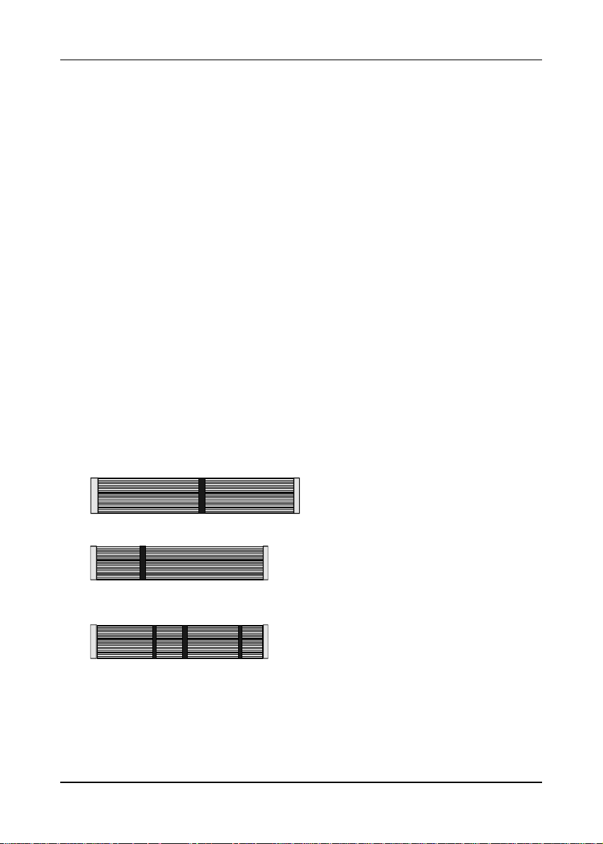
r One 40-pin Ultra DMA-66 IDE connector ribbon cable (Figure 1-1)
* Color coded connection for UDMA/66 cable
Blue to mainboard, Ground in blue, Gray to Master and Black to slave
r One 34-pin floppy disk drive ribbon cable (Figure 1-2a) or (Figure 1-2b)
r One User's Manual
r One CD-ROM that includes
- Acrobat Reader
- Award Flash EPROM Utility, Award DMI Utility for DOS
- Intel Security Driver
- System Health Monitoring Software
- Sound Driver and Utility for Win95/98/NT
- Trend PC-cillin 98 Anti-virus Utility (eight different languages)
- Optional AIRBAG software group including AntiVirus programs and other
helpful utilities
4
Figure 1-1Figure 1-1
Figure 1-1
Figure 1-1Figure 1-1
Figure 1-2aFigure 1-2a
Figure 1-2a
Figure 1-2aFigure 1-2a
Figure 1-2bFigure 1-2b
Figure 1-2b
Figure 1-2bFigure 1-2b
UDMA66 IDE cable
Standard Floppy cable
Optional 5.25 in. floppy cable
Page 5

1-3 Mainboard Layout1-3 Mainboard Layout
1-3 Mainboard Layout
1-3 Mainboard Layout1-3 Mainboard Layout
1-4 Connector and Jumper Reference Chart
Jumpe r &
Co nne cto r
No.
J1 Audio Mono-in/out Connector 17
J2 CD-RO M Audio-in Connector 17
J3 Auxiliary CD-ROM Audio-in C onnector 17
CN4 WOL(Wake-on-LAN) C onnector 19
C N 6 Gr e e n S wit ch C o nne c to r 1 3
Green LED Connector 13
System Reset Switch Connector 13
Turbo LED C onnector 13
K e yb o a rd L o c k & P o w e r I nd icat o r L E D C onne c to r 1 2
Speaker C onnector 13
IDE Activity LED Connecto r 13
O v er - rid e P o w e r B u tt o n C on ne c to r 1 2
CN7 ATX Power Supply Connector 11
JP1 External Clock Frequency Jumper 14
JP4 Clear CM O S Da ta Jumper 14
JP7 PS/2 Keyboa rd/Mouse Power-on Functio n Jumper 14
JP8 Infrared C onnector 15
JP9 Chassis Intrusion M o nitoring C onnector 15
JP1 0 O n B oa rd Audio Jumper 15
JP11/JP12 Audio Line out and Speaker out Jumper 1 6
JP1 3 USB Device Power On Function Jumper 16
FA N 1 / 2/ 3 S y s te m/ C P U /C ha s s is C oo lin g fA N C on ne c to r 1 6
PS /2 Port s PS /2 Mo use and Keyb oa rd P ort s 1 8
U S B P o rt s US B (U nive rsa l S er ia l Bu s) P ort s 1 8
Function
Ref.
Page
Introduction
5
Page 6

Chapter 1
- Memo
6
Page 7
Hardware Setup
Chapter 2Chapter 2
Chapter 2
Chapter 2Chapter 2
HarHar
dd
Har
HarHar
If your mainboard has already been installed in your computer you may still need to
refer to this chapter if you plan to upgrade your system's hardware.
Be sure to disconnect the power cable from the power source before performing
any work on your mainboard, i. e. installing a CPU, memory module,
changing a jumper setting, etc. Not doing so may result in electrical shock!
ware Setupware Setup
d
ware Setup
dd
ware Setupware Setup
2-1 Introduction to Jumpers
Jumpers are used to select between various operating modes. A jumper consists of
a row of gold colored pins that protrude from the surface of the mainboard. It is
important not to confuse jumpers with connectors or headers.
Putting jumper caps on anything that is not a jumper may result in damaging
your mainboard. Please refer to Section 1-3, Mainboard Layout, for the
location of jumpers on your mainboard.
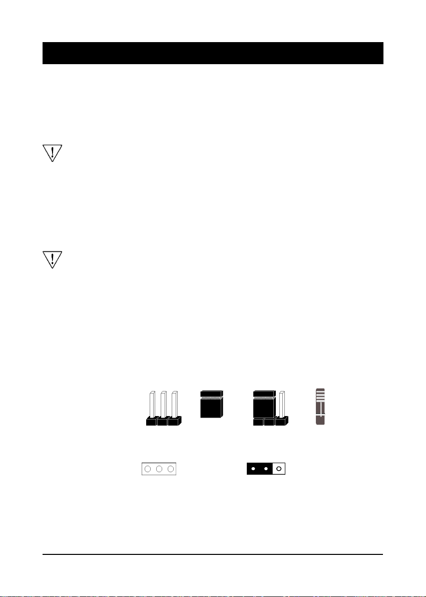
As indicated in Figure 2-1 below, a cap is used to cover the pins of a jumper, resulting
in shorting those pins that it covers. If the cap is removed from the top of the pins,
the jumper is left "open." The number 1 shown both in the diagram below and in
all multiple pin jumper and header diagrams in this manual indicates the pin designated
with the number 1. The numbering of the remaining pins follows in sequence.
Pins SettingCap1
1
A 3-pin jumper
1
A cap over pin 1 and
pin 2 shorts these pins
Figure 2-1Figure 2-1
Figure 2-1
Figure 2-1Figure 2-1
Cap2
7
Page 8

Chapter 2
2-2 Installing an Intel Processor in Slot 1
1. Insert the Intel Pentium II/III/Coppermine/Celeron processor into the retention
mechanism. Press evenly and gently until the snaps on the upper side of the
processor have been inserted into the holes at the top of the retention mechanism.
2. Note that when removing the processor, these snaps should be clicked into a
completely vertical position, leaving your hands free to stabilize the board. Pull
the processor evenly and gently out of the retention mechanism.
3 . Also note that like PCI and ISA slots, Slot 1 has a divider that prevents backwards
insertion of the CPU.
Installing a heat sink with cooling fan is necessary for proper heat dissipation
from your CPU. Failing to install these items may result in overheating and
possible burnout of your CPU.
2-3 Setting Your CPU's Parameters(
SeePU is a new user friendly technology that enables the user to setup a mainboard's
CPU parameters through an easy to use BIOS setup procedure. It is no longer
necessary to make many jumper settings as on conventional mainboards.
1. After installing all your hardware into your PC system, turn on your system's
power. Enter the CMOS Setup Utility by pressing the Delete key when your
BIOS identification screen appears.
2. Move the cursor to SeePU Setup menu and press Enter. Find the CPU Host/PCI
Clock option. Commands for operating the cursor in BIOS are found at the Bottom
of the BIOS screen (Figure 2-2).
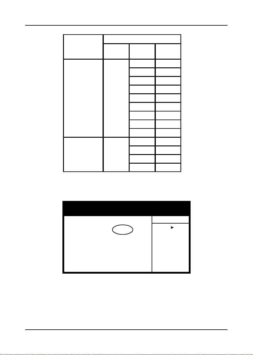
3. Use the CPU Host/PCI Clock option to select your CPU's parameters. Set the
clock ratio (also known as external clock multiplier factor) according to your
processor's specifications (See Figure 2-3).
External clock frequency (JP1) must be selected according to you processor.
Failing to set these jumpers may resulted in system not booting. (See Section
2-4)
You do not need to make voltage settings because SeePU automatically
sets your CPU voltage.
4. Press Esc to return to the CMOS Setup Utility, press F10 to Save and Exit Setup
and choose 'Y' to confirm. The system will automatically reboot and during startup
you will see the correct CPU type shown on the screen.
SeePU
Technology)
8
Page 9
CPU Type
Intel
Pentium II/III
&
Celeron
Processors
Intel
Pentium III
Figure 2-2
External
Clock
100
133
CPU Speed
Frequenc
Ratio
3.5 350
4 400
4.5 450
5 500
5.5 550
6 600
6.5 650
7 700
7.5 750
4 533
4.5 600
5 667
5.5 733
Internal
Clock
Hardware Setup
CMOS Setup Utility - Copyright (C) 1984-1999 Award Software
Auto Detect PCI Clock Enabled
Spread Spectrum Disabled
HOST CPU/PCI Clock Default
CPU Clock Ratio X 3
¡ô¡õ¡÷Move Enter:Select +/-/PU/PD:Value F10:Save ESC:Exit F1:Genaral Help
F5:Previous Values F6:Fail-Safe Defaults F7:Optimized Defaults
SeePU Setup
Items Help
Menu Level
Figure 2-3
9
Page 10

Chapter 2
Overclocking
Operating a CPU at a higher frequency than it's specification allows is called
overclocking. If the CPU frequency is set at a higher frequency than it's specification
allows, it may or may not run at that frequency, depending on the quality of your
CPU and the extent to which the frequency has been overset. The mainboard
manufacturer highly discourages overclocking as it may result in data loss, CPU
burnout, system failure, etc.
Many Intel processors are frequency locked processors and are not able to perform
overclocking. Regardless of whether the processor is a frequency locked, overclocking
may cause some processors to hang when turning on the system. When the processor
hangs, the screen remains blank and the system does not boot. To solve this problem,
do the following.
1. Turn off the computer and then press the Home key on your keyboard
2. Turn on your computer, wait for five seconds and then release the Home key.
3. Enter BIOS and reconfigure your CPU parameters as described in this section.
10
Page 11
Hardware Setup
2-4 Connector and Jumper Settings
Connectors are used to link the system board with other parts of the system, including
the power supply, the keyboard, and the various controllers on the front panel of
the system case.
The power supply connector is the last connection to be made while installing a
mainboard. Before connecting the power supply, please make sure it is not
connected to the power source.
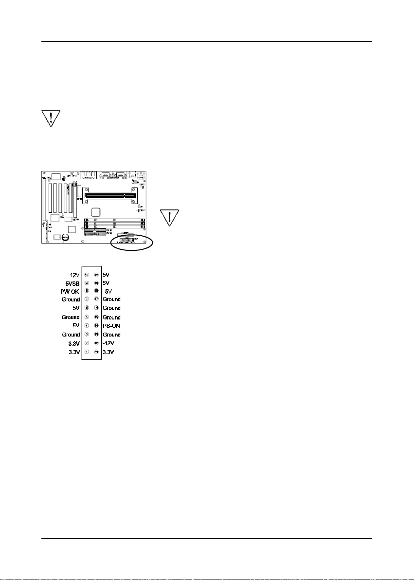
ATX Power Supply Connector (CN7)
The power cord leading from the system's power supply
to the external power source must be the very last part
connected when assembling a system.
To support this function, a switching power
supply with a minimum of 750mA 5VSB is
required.
The ATX power supply provides a single 20-pin
connector interface which incorporates standard +/-5V,
+/-12V, optional 3.3V and Soft-power signals. The Softpower signal, a 5V trickle supply is continuously
supplied when AC power is available. When the system
is in the Soft-Off mode, this trickle supply maintains the
system in it's minimum power state.
Power-On By ModemPower-On By Modem
Power-On By Modem
Power-On By ModemPower-On By Modem
While in Soft-off state, if an external modem ring-up signal occurs, the system wakes up
and can be remotely accessed. You may enable this function in BIOS's Power
Management Setup menu.
Poly-fuse Over Current Protection
The poly-fuse protects the system from dangerous voltages the system might be
exposed to via the keyboard or USB connectors. In case of such exposure, the polyfuse will immediately be disconnected from the circuit, just like a normal fuse. After
being disconnected for a certain period of time, the poly-fuse will return to its normal
state, after which the keyboard or USB can function properly again. Unlike
conventional fuses, the poly-fuse does not have to be replaced, relieving the user
wasted time and inconvenience.
11
Page 12
Chapter 2
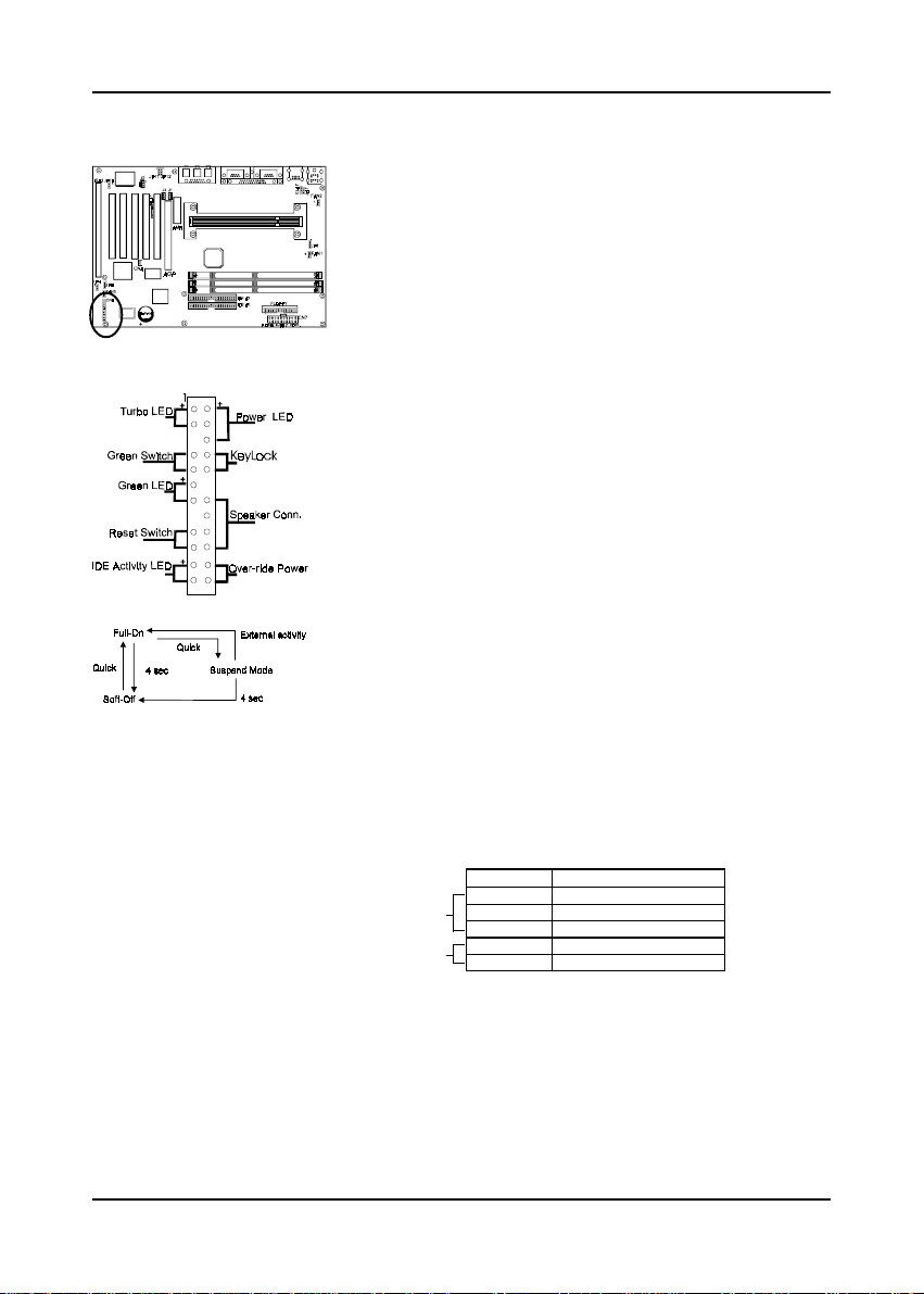
Front Panel Connector Set (CN6) A through F
A. Over-ride Power Button Connector
The power button on the ATX chassis can be used as a
normal power switch as well as a device to activate
Advanced Power Management Suspend mode. This mode
is used for saving electricity when the computer is not in use
for long periods of time. The Soft-OFF by PWR-BTTN
function in BIOS's Power Management Setup menu must be
set to "Delay 4 Sec." to activate this function.
When the Soft-OFF by PWR-BTTN function is enabled,
pushing the power button rapidly will switch the system to
Suspend mode. Any occurrence of external activities such
as pressing a key on the keyboard or moving the mouse will
bring the system back to Full-On. Pushing the button while
in Full-On mode for more than 4 seconds will switch the
system completely off. See Over-ride Power Button
Operation diagram.
B. Keyboard Lock & Power Indicator LED
Connector
Plugging this connector into the lock on the front panel
Over-ride Power ButtonOver-ride Power Button
Over-ride Power Button
Over-ride Power ButtonOver-ride Power Button
Operation Operation
Operation
Operation Operation
of the system case allows the lock to enable or disable
the keyboard. This function provides limited security
against casual intruders. The power indicator LED shows
the system's power status. It is important to pay attention
to the correct cables and pin orientation (i.e., not to
reverse the order of these two connectors.)
Pin Definition
1 +5V DC
Power Good LED
Keyboard Lock
2 No Connect
3 Ground
4 Keylock
5 Ground
Software Power-Off Control
This mainboard can be powered down using the Windows 95 Software Power-Off
function. To power down your computer, click the START button on the Windows 95
task bar. Select "Shut Down The Computer" and the system turns off. The message "It
is now safe to turn off your computer" will not be shown when using this function.
12
Page 13
Hardware Setup
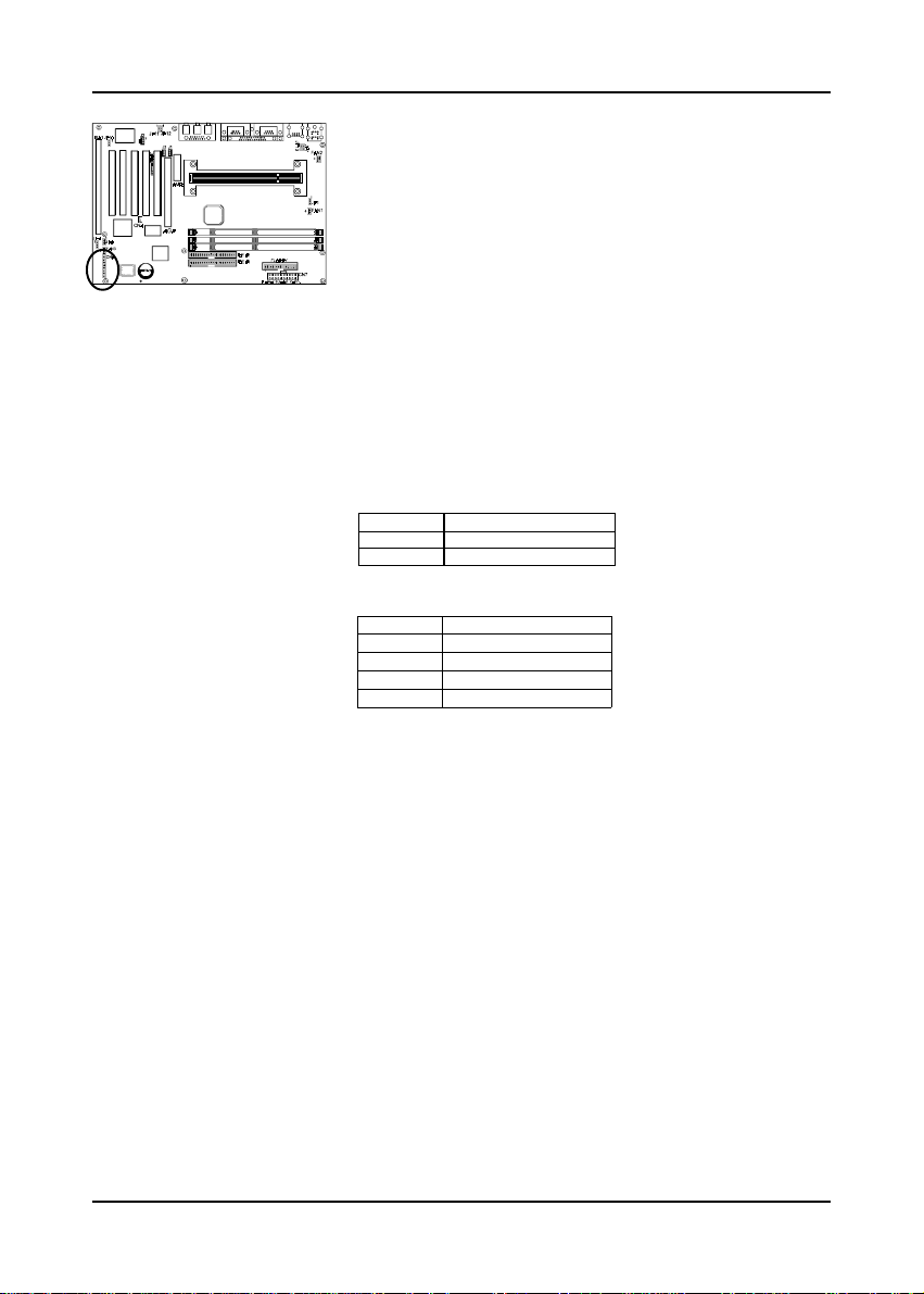
C. Green Switch/Green LED Connector
Some ATX cases provide a Green switch which is used
to put the system in Suspend mode. In Suspend mode,
the power supply to the system is reduced to a trickle,
the CPU clock is stopped, and the CPU core is in it's
minimum power state. The system is woken up whenever
the keyboard or mouse is touched. The system resumes
in different ways as defined by Power Management
Setup screen in BIOS.
D. System Reset Switch Connector
This connector should be connected to the reset switch
on the front panel of the system case. The reset switch
allows you to restart the system without turning the
power off.
Pin Definition
1 Sys tem
2 GND
E. Speaker Connector
PIN Definition
1 Speaker Signal
2 NC
3 NC
4 +5V DC
F. IDE Activity LED Connector
The IDE activity LED lights up whenever the system
reads/writes to the IDE devices.
G. Turbo LED Connector
The massage indicator LED lights up whenever the
system went on suspend mode.
Blinking LED in Suspend Mode
While in Suspend mode, the LED light on the front panel of your computer will flash.
Suspend mode is entered by pressing the Override Power Button, pushing the Green
button on your ATX case, or enabling the Power Management and Suspend Mode
options in BIOS's Power Management menu. (See section 3-4)
13
Page 14
Chapter 2
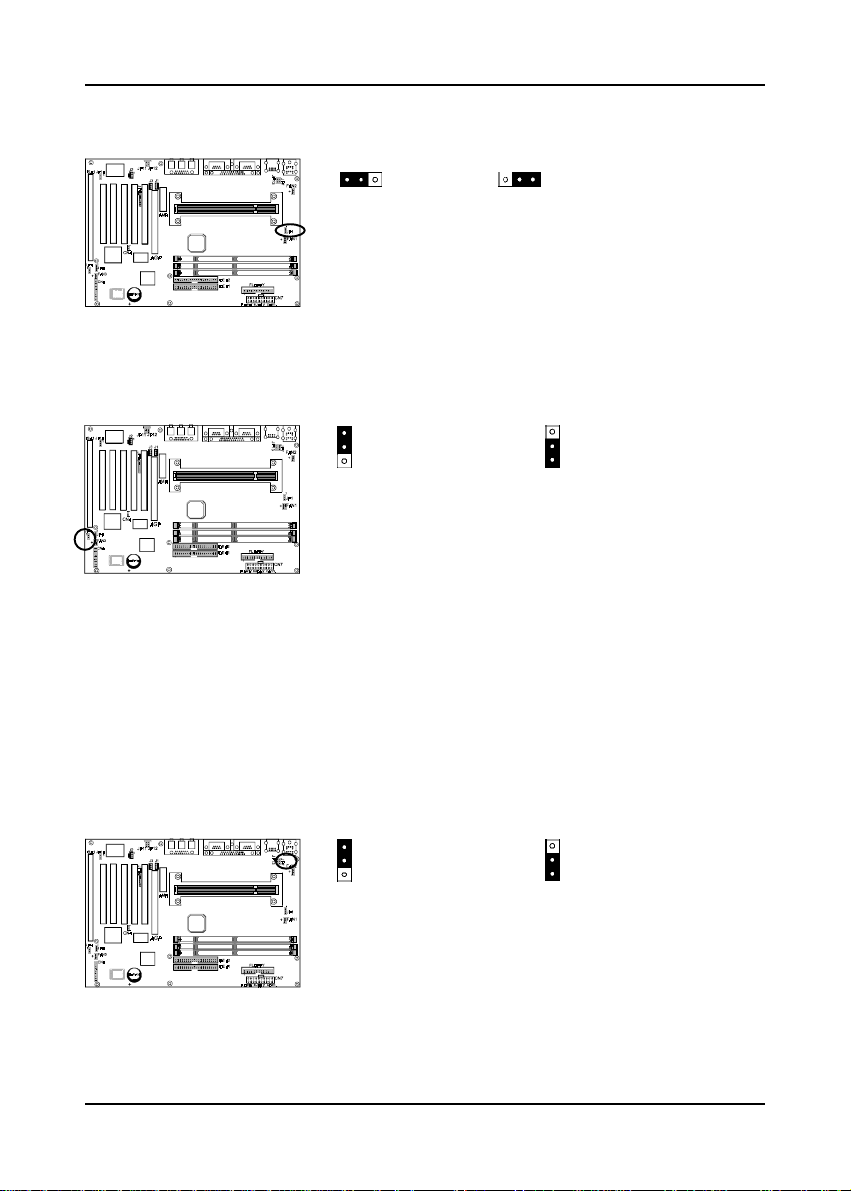
External Clock Frequency (JP1)
1
(Default)
CPU
This jumper allows the external clock frequency to be
determined either by the CPU or the user. If set to
pins 1-2, the CPU determines the external clock speed.
If set to pins 2-3, the external clock is always 133MHz.
Clear CMOS Data Jumper (JP4)
1 1
Normal (default)
To clear the contents of the CMOS, please follow the
steps below.
1.Disconnect the system power supply from the power
source.
2.Set the jumper cap at location 2~3 for 5 seconds,
then set it back to the default position.
3.Connect the system's power and then start the
system.
4.Enter BIOS's CMOS Setup Utility and choose Load
Setup Defaults. Type Y and press enter.
5.Set the system configuration in the Standard CMOS
Setup menu.
1
133MHz
Clear CMOS data
PS/2 Keyboard/Mouse Power-on Function (JP7)
1 1
Disabled
This board is able to be turned on by the PS/2 keyboard
(hot key/Password) or a PS/2 mouse click. To use this
function, select a device of your choice at the Power
on Function option in BIOS's Integrated Peripherals
screen . You must also set this jumper's cap to pins 23 to use this function.
14
Enabled
Page 15
Infrared Connector (JP8)
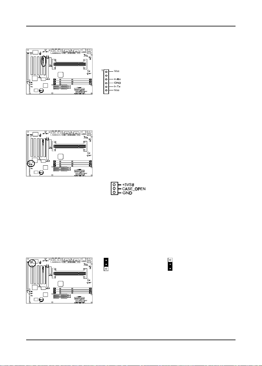
If you enable the IR Address Select in BIOS's Integrated
Peripherals menu the IR port will support IR functions.
Chassis Intrusion Monitoring Connector (JP9)
This board supports the chassis instruction detection
feature of the management extension hardware by means
of a mechanical or photo sensor switch attached to the
motherboard through this 1x3-pin chassis security header.
The mechanical switch is set to open for normal computer
operation.
1
Hardware Setup
Onboard Audio Jumper(JP10)
1 1
Enabled (default)
This function allows you to enable and disable the on
board audio. You must set the jumper's cap to pins 12 to enable or set pins 2-3 to disable this function.
Disabled
15
Page 16
Chapter 2
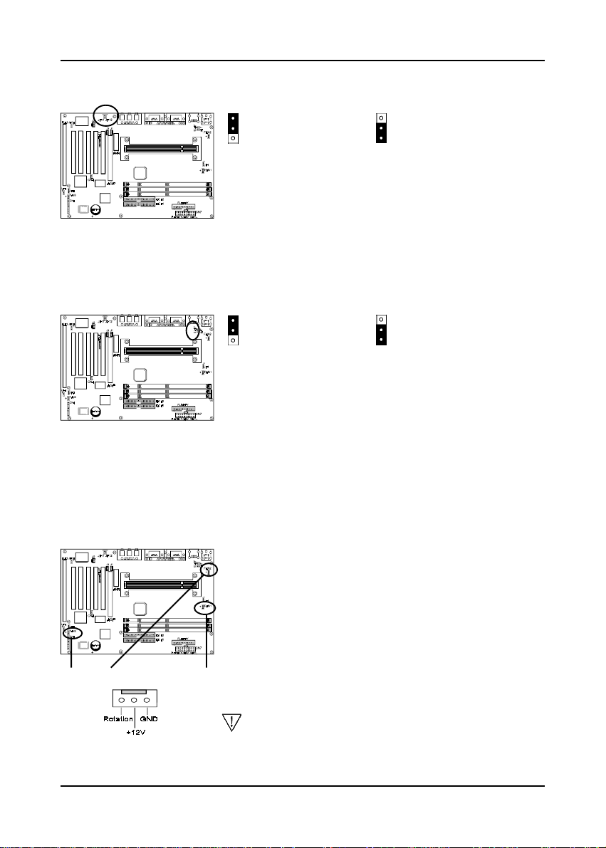
Audio Line out and Speaker out Jumper(JP11/JP12)
1
Line-Out
This jumper allows you to select between audio line-out or
speaker out function. Set both JP11 and JP12 pins to 1-2
for line-out function or set both JP11 and JP12 pins to 23 for speaker out function..
1
Speaker-Out
USB Device Power On Jumper (JP13)
1
Disabled
This board is able to be turned on by a USB keyboard
(hot key/Password) or a USB mouse click. To use this
function, select a device of your choice at the Power on
Function option in BIOS's Integrated Peripherals screen.
You must also set this jumper's cap to pins 2-3 to use
this function.
1
Enabled
System/CPU/Chassis Cooling Fan Connectors (FAN1/FAN2/FAN3)
These added connectors allow the fan to draw their power
from the mainboard instead of the disk drive connector.
The board's management extension hardware is able to
detect the CPU and system fan speed in rpm (revolutions
per minute). These connectors supports 3-pin cooling
fans with minimum of 3500 RPM. The wiring and plug may
FAN3(Chassis) FAN2 (CPU) FAN3(System)
16
vary depending on the manufacturer. On standard fans,
the red is positive (+12V), the black is ground, and the
yellow wire is the rotation signal.
FAN3 is an independent power line that is not control by
system health monitor and power management.
Page 17
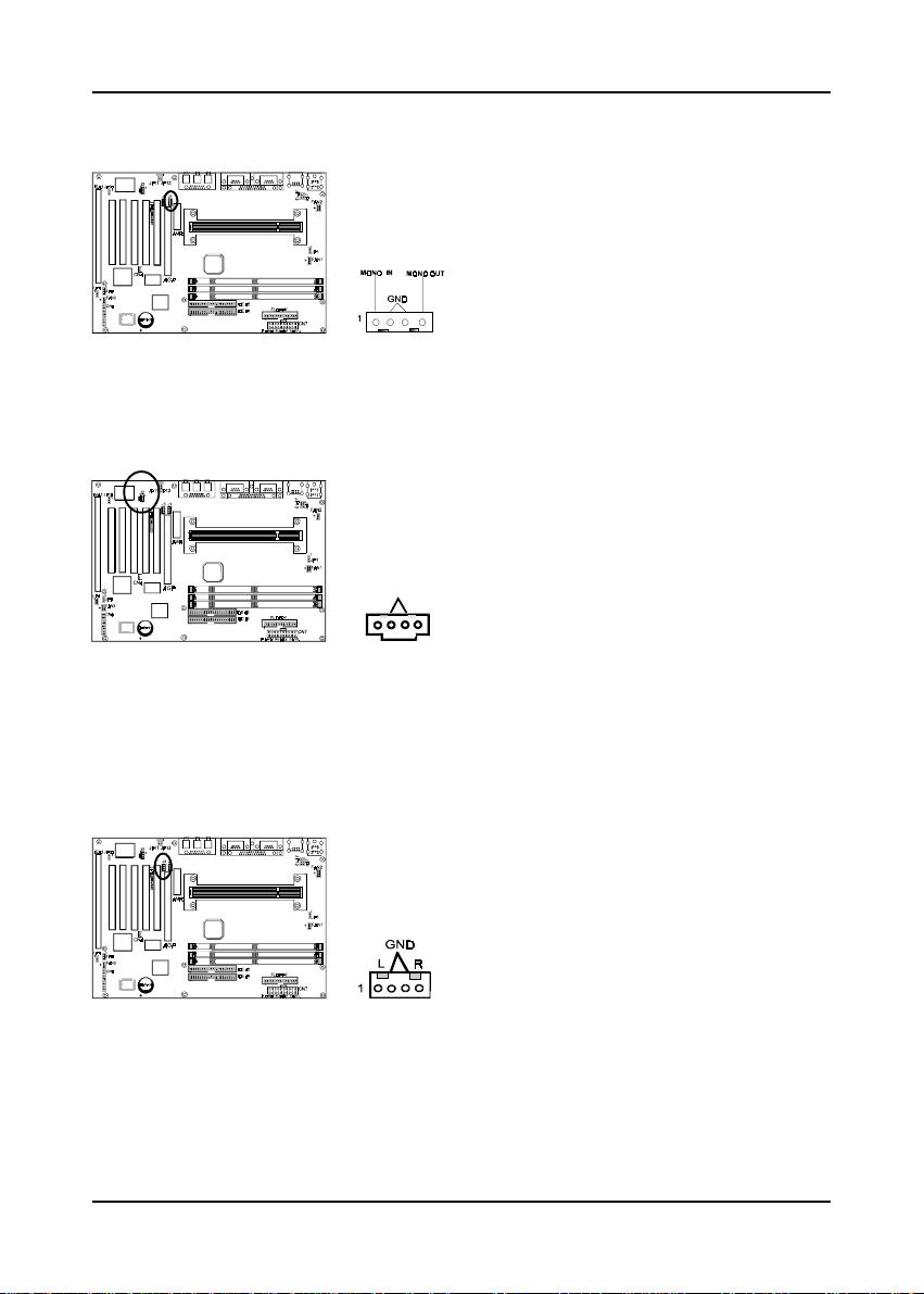
Audio Mono -in/out (J1)
G
CD-ROM Audio-in (J2)
Hardware Setup
Use the mono audio cable enclosed with your CD-ROM
disk drive to connect the CD-ROM to your mainboard.
This will enable mono audio in/out function.
Use the audio cable enclosed with your CD-ROM disk
drive to connect the CD-ROM to your mainboard. This
will enable your CD-ROM's audio function.
ND
L
R
1
Auxiliary CD-ROM Audio-in (J3)
Use the auxiliary audio cable enclosed with your CDROM disk drive to connect the CD-ROM to your
mainboard. This will enable your CD-ROM's audio
function.
17
Page 18
Chapter 2
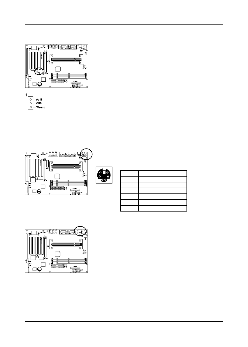
WOL (Wake-on-LAN) Connector (CN4)
Enable the Wake Up On LAN selection in BIOS's Power
Management Menu to use this function. The capability
to remotely manage PCs on a network is a significant
factor in reducing administrative and ownership costs.
Magic Packet technology is designed to give WOL
(Wake-on-LAN) capability to the LAN controller. When
a PC capable of receiving wake up command goes to
sleep, the Magic Packet mode in the LAN controller is
enabled. When the LAN controller receives a Magic
Packet frame, the LAN controller will wake up the PC.
This header is used to connect an add-in NIC (Network
Interface Card) which gives WOL capability to the
mainboard.
PS/2 Mouse and Keyboard Ports
If a PS/2 mouse is used, BIOS will automatically detect
and assign IRQ12 to the PS/2 mouse.
Pin Definition
1 Data
2 No Connect
3 Ground
4 +5V (fused)
5 Clock
6 No Connect
USB(Universal Serial Bus) Ports
If you want to use a USB keyboard, you must enable
the USB keyboard support function in BIOS's Integrated
Peripherals menu. USB is an open industry standard,
providing a simple and inexpensive way to connect up
to 125 devices to a single computer port. Keyboards,
mice, tablets, digitizers, scanners, bar-code readers,
modems, printers and many more can all be used at the
same time.
USB is a dynamically reconfigurable serial bus with an
elementary data rate of 12Mbps. Based on off the shelf,
low cost micro-controller technology, its modular layered
software protocol supports sophisticated devices and
application programs.
18
Page 19
Hardware Setup
2-5 Direct Rambus Memory Subsystem
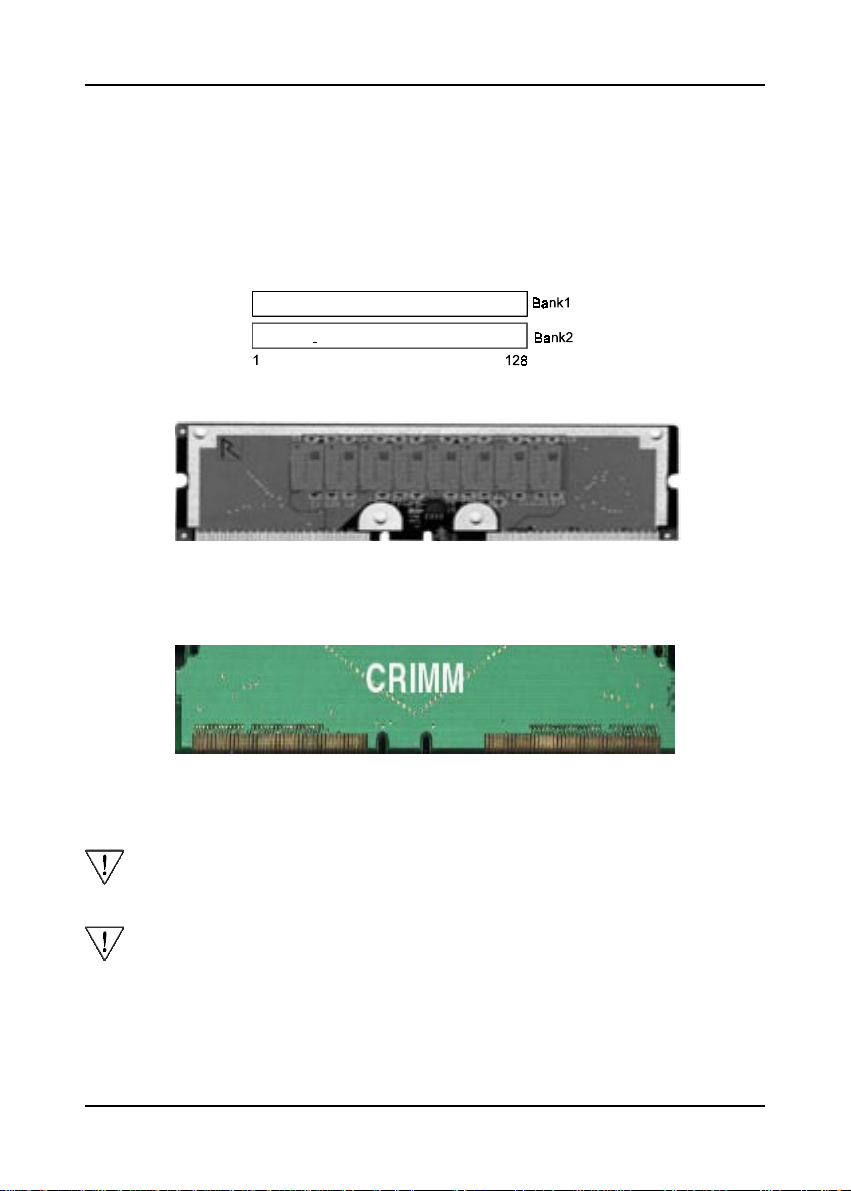
The Direct Rambus Memory Subsystem consists two banks and the memory size
ranges from 64~512MBytes with supports up to 32 DRDRAM devices . It does not
matter which bank to use but need to fill in the rest of the banks with CRIMMs.(see
figure 2-5)
RIMM1
RIMM2
Figure 2-4 Direct RDRAM Module
Figure 2-5 CRIMM Module
The compatibility with 512MB and up Direct RDRAM is still under testing and
cannot be guaranteed.
All unused banks must be filled with CRIMM in order the Direct Rambus
Memory Subsystem to function.
19
Page 20

Chapter 2
- Memo
20
Page 21
Award BIOS Setup Program
Chapter 3Chapter 3
Chapter 3
Chapter 3Chapter 3
33
3
33
Award BIOS Setup Program
Award's BIOS ROM has a built-in setup program that allows users to modify the basic
system configuration. This information is stored in CMOS RAM so that it can retain
the setup information, even when the power is turned off.
When you turn on or restart the system, press the Delete key to enter the Award
BIOS setup program. The primary screen as shown in Figure 3-1 is a list of the menus
and functions available in the setup program. Select the desired item and press enter
to make changes. Operating commands are located at the bottom of this and all other
BIOS screens. When a field is highlighted, on-line help information is displayed
on the right side of the screen.
CMOS Setup Utility- Copyright (C) 1984-1999 Award Software
Standard CMOS Features
Advanced BIOS Features
Advanced Chipset Features
Integrated Peripherals
Power Management Setup
PnP/PCI Configurations
PC Health Status
Esc : Quit
F10 : Save & Exit Setup
Figure 3-1 Setup Program Initial Screen
SeePU Setup
Load Fail-Safe Defaults
Load Optimized Defaults
Set Supervisor Password
Set User Password
Save & Exit Setup
Exit Without Saving
¡ô¡õ¡õ¡ô : Select Item
Time, Date, Hard Disk T ype...
21
Page 22

User's Manual
- Memo
22
 Loading...