

Page 1
Introduction
Chapter 1
Introduction
1-1 Product Specifications
rr
r Processor
rr
- Supports up to 450 MHz Intel Pentium® II processors and Celeron
processors with MMX technology
- Slot 1 CPU socket with folding retention mechanism
- High efficiency Switching Power Module (1.8v ~ 3.5v, 0.1v increments)
- Supports 66/100 MHz system clock speeds
- Innovative SeePU technology (software CPU installation with no jumper
settings)
Supports 75/83/103/112//133 MHz system clock speeds for over-clocking
possibility.(See Section 2-3 Overclocking)
rr
r Chipset
rr
- Intel 82440BX two chip AGPset
rr
r DRAM Memory
rr
- Three 3.3V 168-pin DIMM sockets support up to 384 MB
- Supports 16/32/64/128MB, 64/72-bit unbuffered Synchronous DIMM
modules
- Provides single-bit ECC capability
10ns or faster SDRAM DIMM modules with SPD are required for
100MHz frequency clock speed
Because 256MB unbuffered DIMM and Registered DIMM modules are
not yet mainstream, their compatibility can not be guaranteed. (See
Section 2-5 for details.)
rr
r Expansion Slots
rr
- One 32-bit AGP slot (Rev 1.0 compliant)
- Four 32-bit PCI slots (Rev 2.1 compliant)
- Two 16-bit ISA slots (one PCI/ISA shared slot)
rr
r BIOS
rr
- Award System BIOS, supports PnP, APM, DMI & Multi-device booting
features i.e. floppy, LS120, CD-ROM, HDD(IDE, SCSI), ZIP-ATAPI etc.
- Includes Trend ChipAway Virus protection for virus-free boot and virus
free operating system
1
Page 2

Chapter 1
@
The Trend ChipAway Virus is a rule-based anti-virus technology and
does not require periodical updates of virus code
rr
r Two Ultra DMA-33 PCI IDE Ports
rr
- Supports up to PIO Mode 4, Multi-word Mode 2 and Ultra DMA-33 timings
- Bus Mastering software drivers for all well known multi-task operating
systems
rr
r On-board Ultra I/O
rr
- ITE 8671 I/O chip
- One Parallel (SPP/ECP/EPP) and two Serial (16550A compliant) ports
- One floppy disk drive connector supports up to 2.88MB, Japanese 3-Mode,
and 1Mbps transfer rates
- IrDA IR function supports up to 115.2Kbps
rr
r Two Channel USB Ports
rr
Now under compatibility testing with different peripherals
rr
r Board Dimensions
rr
- ATX form factor, 305mm x 190mm, 4 Layers
- Six mounting holes
rr
r Advanced Management Features
rr
- Software power off control, Power-on by modem, Power on by alarm,
Power-on by keyboard, Over-ride power button, Power failure recovery,
Blinking LED in Suspend, Power on by mouse, Power on safe guard, Wake
Up On LAN, etc.
- Poly-fuse over-current protection for USB and keyboard
- Flash BIOS protect via BIOS
- Supports SB-link header for Creative PCI audio cards
- Supports optional FAN-II (EISCA v1.0 compliant cooling fan, see Appedinx
III) or on-board Management Extension Hardware and includes system
monitoring software to streamline PC management
- Meets EPA Green PC standard: power consumption under 30W in Doze,
Standby, and Suspend modes
- ACPI features ready when ACPI-enabled O/S is available
2
Page 3

rr
r Switching Power Supply Requirement (at least 200 Watts)
rr
Introduction
Output Voltage
+12V +/- 5% 0
+5V +/- 5% 1
+3.3V +/- 5% 10*
-5V +/- 10% 0
-12V +/- 10% 0
+5VSB +/- 5% 0.75
Max. Regulation
Requirement
Table 1-1Table 1-1
Table 1-1
Table 1-1Table 1-1
Min. Current
Requirement (Amps)
* 3.3V at 10Amps is necessary too guarantee full loading operation
because some AGP cards and memory modules have high current
consumption.
@
The on-board 3.3v regulator provides maximum 6Amp current drive
capability for AGP cards and memory modules.
3
Page 4
Chapter 1
1-2 Package Contents1-2 Package Contents
1-2 Package Contents
1-2 Package Contents1-2 Package Contents
This product comes with the following components:
r One mainboard
r On-board Slot 1 foldable retention mechanism and four screws
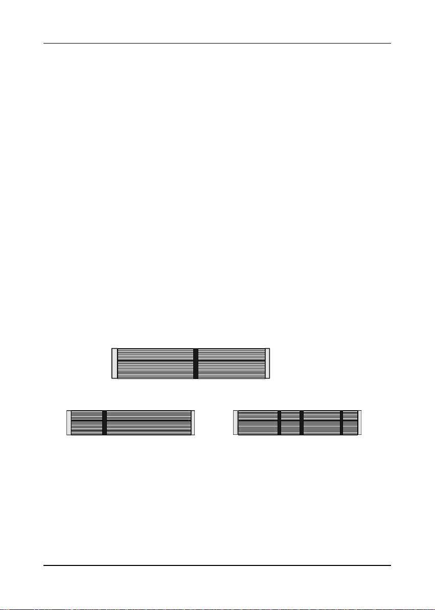
r One 40-pin IDE connector ribbon cable (Figure 1-1)
r One 34-pin floppy disk drive ribbon cable (Figure 1-2a) or (Figure 1-2b)
r One User's Manual
r One CD-ROM that includes
- Acrobat Reader
- Audio Driver and Utility
- Award Flash EPROM Utility, Award DMI Utility for DOS
- Intel Bus Master IDE drivers for Win95, WinNT, and OS/2
- Exclamation Mark Remover Utility
- System Health Monitoring Software
- Trend PC-cillin Anti-virus v3.0(OEM version) Utility in eight different
languages
4
Figure 1-2aFigure 1-2a
Figure 1-2a
Figure 1-2aFigure 1-2a
Figure 1-1Figure 1-1
Figure 1-1
Figure 1-1Figure 1-1
Standard Floppy cable
Figure 1-2bFigure 1-2b
Figure 1-2b
Figure 1-2bFigure 1-2b
IDE cable
Optional 5.25 in. floppy cable
Page 5
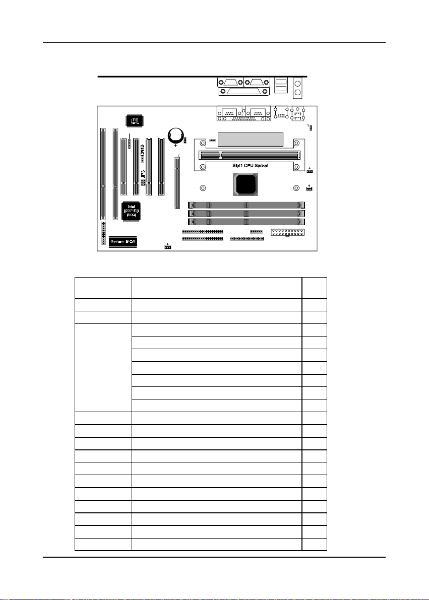
1-3 Mainboard Layout1-3 Mainboard Layout
1-3 Mainboard Layout
1-3 Mainboard Layout1-3 Mainboard Layout
PCB
SL1
SL2
CN9
PCI1
PCI3PCI4
PCI2
IR
Battery
AGP port
JP4
Introduction
Back P anel I/O C onnector
COM2
Printer
COM2
Printer
JP9
1
1
Switching power module
COM1
COM1
USB2
USB1
USB x 2
K/B
Mouse
PS/2 Mouse
& K/B Conn.
JP1
1
1
CN13
1
IDE #2
1
FAN3
IDE #1
Intel
82440BX
CN15
1
Floppy drive po rt
1
Power supply conn.
1-4 Connector and Jumper Reference Chart
Jumper &
Connector No.
CN9 Infrared connector 14
CN10 WOL (Wake on LAN) connector 14
Keyboard lock & Power indicator LED connector 12
System reset switch connector 13
Speaker connector 13
CN13
Green switch & Green LED connector 13
Turbo LED connector 13
IDE activity LED connect or 13
Over ride power button (for ATX power supply) 12
CN14 ATX Power supply connector 11
CN15 FAN-II connector 53
CN22 Modem telephony connector 16
FAN1 CPU cooling fan connector 14
FAN2/FAN3 System cooling fan connector 14
JP1 Power on by keyboard jumper 15
JP3 Creative's SB-LINK connector 15
JP4 Clear CMOS data jumper 15
JP9 External clock frequency jumper 10
Ports PS/2 mouse and keyboard ports 16
Ports USB (Universal Serial Bus) ports 16
Function Page
DIMM
FAN1
FAN 2
CN14
5
Page 6

Chapter 1
- Memo
6
Page 7
Hardware Setup
Chapter 2Chapter 2
Chapter 2
Chapter 2Chapter 2
Hardware SetupHardware Setup
Hardware Setup
Hardware SetupHardware Setup
If your mainboard has already been installed in your computer you may still need
to refer to this chapter if you plan to upgrade your system's hardware.
Be sure to disconnect the power cable from the power source before performing
any work on your mainboard, i. e. installing a CPU, memory module, changing
a jumper setting, etc. Not doing so may result in electrical shock!
2-1 Introduction to Jumpers
Jumpers are used to select between various operating modes. A jumper consists
of a row of gold colored pins that protrude from the surface of the mainboard. It
is important not to confuse jumpers with connectors or headers.
Putting jumper caps on anything that is not a jumper may result in
damaging your mainboard. Please refer to Section 1-3, Mainboard
Layout, for the location of jumpers on your mainboard.
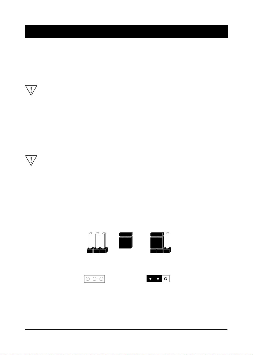
As indicated in Figure 2-1 below, a cap is used to cover the pins of a jumper, resulting
in shorting those pins that it covers. If the cap is removed from the top of the pins,
the jumper is left "open." The number 1 shown both in the diagram below and in
all multiple pin jumper and header diagrams in this manual indicates the pin designated
with the number 1. The numbering of the remaining pins follows in sequence.
Pins SettingCap
1
A 3-pin jumper
1
A cap over pin 1 and
pin 2 shorts these pins
Figure 2-1Figure 2-1
Figure 2-1
Figure 2-1Figure 2-1
7
Page 8
Chapter 2
2-2 Installing an S.E.C. Processor in Slot 1
1. Insert the Pentium II processor into the retention mechanism. Press evenly and
gently until the snaps on the upper side of the processor have been inserted into
the holes at the top of the retention mechanism.
2. Note that when removing the processor, these snaps can be clicked into a
completely vertical position, leaving your hands free to stabilize the board. Pull
the processor evenly and gently out of the retention mechanism.
3. Also note that like PCI and ISA slots, Slot 1 has a divider that prevents backwards
insertion of the CPU.
Installing a heat sink and cooling fan is necessary for proper heat dissipation
from your CPU. Failing to install these items may result in overheating and
possible burn-out of your CPU.
2-3 Setting Your CPU's Parameters(
SeePU
Technology)
SeePU is a new user friendly technology that enables the user to setup a mainboard's
CPU parameters through an easy to use BIOS setup procedure. It is no longer
necessary to make many jumper settings as on conventional mainboards.
1. After installing all your hardware into your PC system, turn on your system's
power. Enter the CMOS Setup Utility by pressing the Delete key when your
BIOS identification screen appears.
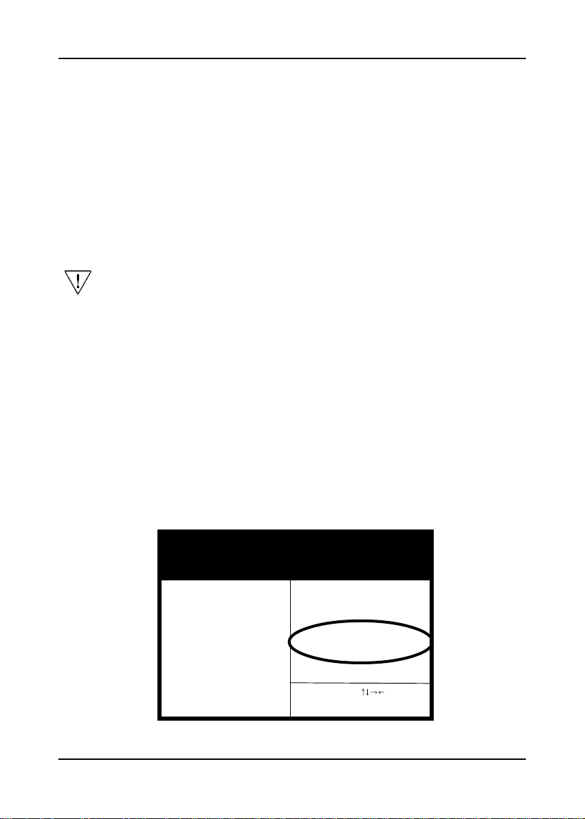
2. Move the cursor to SeePU & Chipset Setup menu and press Enter. Find the CPU
Setup commands at the right hand part of the BIOS screen (Figure 2-2) Commands
for operating the cursor in BIOS are found at the lower right of the BIOS screen.
ROM PCI / ISA BIOS (2A69KC39)
SeePU & CHIPSET SETUP
AW ARD SOFTW ARE, INC.
SDRAM CAS latency Time : 3
DRAM Data Integrity Mode : Non-ECC
System BIOS Cacheable : Disabled
Video BIOS Cacheable : Disabled
Video RAM Cacheable : Disabled
8 Bit I/O Recovery Time : 1
16 Bit I/O Recovery Time : 1
Memory Hole At 15M-16M : Disabled
Passive Release : Enabled
Delayed Transaction : Enabled
AGP Aperture Size (MB) : 64
Power Failure Recovery : Disabled
Spectrum Spread : Disabled
Flash BIOS Protection : Disabled
***** CPU Setup *****
CPU Type :350MHz (100*3.5)
ESC : Quit
F1 : Help
F5 : Old Values
F7 : Load Setup Defaults
Figure 2-2Figure 2-2
Figure 2-2
Figure 2-2Figure 2-2
:Select Item
PU/PD/+/- : Modify
(Shift) F2 : Color
8
Page 9
Hardware Setup
3. Change the CPU Type according to the speed of your Pentium II processor. See
Figure 2-3 for frequency specifications.
CPU Type
Pentium II
processor
External Clock
66
100
Figure 2-3Figure 2-3
Figure 2-3
Figure 2-3Figure 2-3
CPU Speed
Frequency
Ratio
3.5 233
4 266
4.5 300
5 333
3.5 350
4 400
Internal Clock
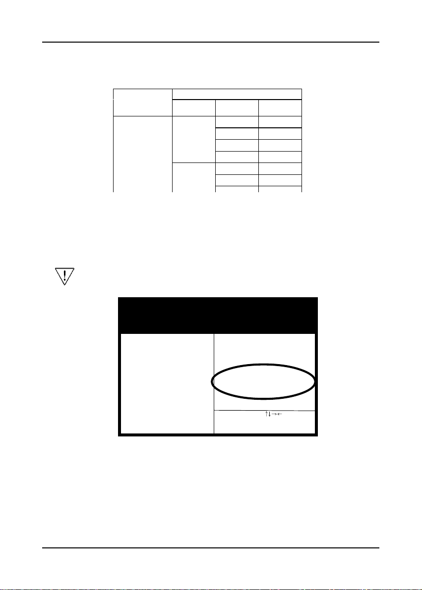
4. Use the User Define option to custom set your CPU's parameters. Set the
frequency ratio (also known as external clock multiplier factor) and CPU bus
frequency according to your processor's specifications. See Figure 2-4.
You do not need to make voltage settings because SeePU automatically
sets your CPU voltage.
ROM PCI / ISA BIOS (2A69KC39)
SeePU & CHIPSET SETUP
A WARD SOFTW ARE, INC.
SDRAM CAS latency Time : 3
DRAM Data Integrity Mode : Non-ECC
System BIOS Cacheable : Disabled
Video BIOS Cacheable : Disabled
Video RAM Cacheable : Disabled
8 Bit I/O Recovery Time : 1
16 Bit I/O Recovery Time : 1
Memory Hole At 15M-16M : Disabled
Passive Release : Enabled
Delayed Transaction : Enabled
AGP Aperture Size (MB) : 64
Power Failure Recovery : Disabled
Spectrum Spread : Disabled
Flash BIOS Protection : Disabled
***** CPU Setup *****
CPU Type : User's Define
Frequency Ratio : 3.5X
CPU Bus Frequency :100MHz
ESC : Quit
F1 : Help
F5 : Old Values
F7 : Load Setup Defaults
Figure 2-4Figure 2-4
Figure 2-4
Figure 2-4Figure 2-4
:Select Item
PU/PD/+/- : Modify
(Shift) F2 : Color
5. Press Esc to return to the CMOS Setup Utility, press F10 to Save and Exit Setup
and choose 'Y' to confirm. The system will automatically reboot and during startup
you will see the correct CPU type indicated on the start-up screen screen.
9
Page 10
Chapter 2
External Clock Frequency Jumper (JP9)
1
1
1
1
1
1
1
1
1
1
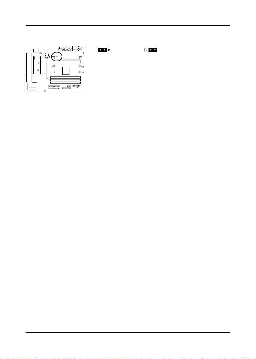
This jumper allows the external clock frequency to be
determined either by the CPU or the user. If set to pins
1-2, the CPU automatic determines the external clock
speed. If set to pins 2-3, the external clock is always
(Default)
CPU
100MHz.
1
100MHz
Overclocking
Operating a CPU at a higher frequency than it's specification allows is called
overclocking. If the CPU frequency is set at a higher frequency than it's specification
allows, it may or may not run at that freqency, depending on the quality of your CPU
and the extent to which the frequency has been overset. The mainboard manufacturer
highly discourages overclocking as it may result in data loss, CPU burn-out, system
failure, etc.
Many Pentium II processors are frequency locked processors and are not able to
perform overclocking. Regardless of whether the processor is a frequency locked,
overclocking may cause some processors to hang when turning on the system. When
the processor hangs, the screen remains blank and the system does not boot. To
solve this problem, do the following.
1. Turn off the computer and then press the Home key on your keyboard
2. Turn on your computer, wait for five seconds and then release the Home key.
(Pressing the Home key allows the computer to boot at a low system speed.
For example, for 66MHz external clock CPUs, the CPU boot-up speed is
233MHz. For 100MHz external clock CPUs, the CPU boot-up speed is
350MHz.)
3. Enter BIOS and reconfigure your CPU parameters as described in this section.
10
Page 11
Hardware Setup
2-4 Connector and Jumper Settings
Connectors are used to link the system board with other parts of the system, including
the power supply, the keyboard, and the various controllers on the front panel of
the system case.
The power supply connector is the last connection to be made while installing a
mainboard. Before connecting the power supply, please make sure it is not
connected to the power source.
ATX Power Supply Connector (CN14)
1
1
1
1
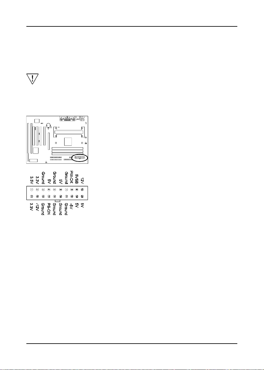
This mainboard requires a power supply of at least 200
watts. The power cord leading from the system's
power supply to the external power source must be
the very last part connected when assembling a system.
1
1
1
1
1
The ATX power supply provides a single 20-pin connector
interface which incorporates standard +/-5V, +/-12V,
optional 3.3V and Soft-power signals. The Soft-power
signal, a 5V trickle supply is continuously supplied when
AC power is available. When the system is in the SoftOff mode, this trickle supply maintains the system in it's
minimum power state.
Software Power-Off Control
This mainboard can be powered down using theWindows 95 Software Power-Off
function. To power down your computer, click the START button on the Windows 95
task bar. Select "Shut Down The Computer" and the system turns off. The message "It
is now safe to turn off your computer" will not be shown when using this function.
Power-On By ModemPower-On By Modem
Power-On By Modem
Power-On By ModemPower-On By Modem
While in Soft-off state, if an external modem ring-up signal occurs, the system wakes
up and can be remotely accessed. Enable this function in BIOS's Power Management
Setup menu. (See section 3-4)
11
Page 12
Chapter 2
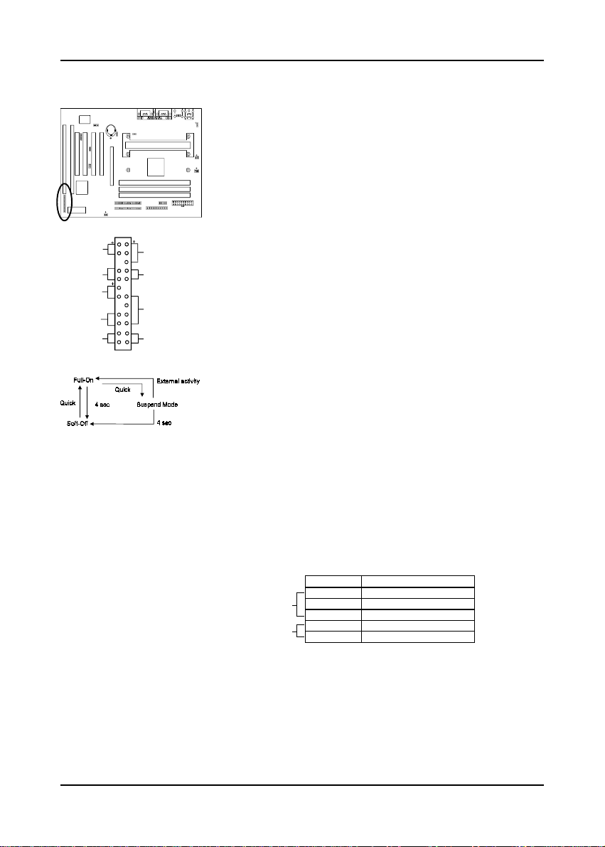
Front Panel Connector Set (CN13) A through G
1
1
1
1
1
G
R
ID
E
Over-ride Power ButtonOver-ride Power Button
Over-ride Power Button
Over-ride Power ButtonOver-ride Power Button
Operation Operation
Operation
Operation Operation
1
1
T
u
b
r
o
L
E
D
e
n
S
w
itc
h
e
r
E
D
G
e
r
e
n
L
e
s
e
t
S
w
itc
h
+
A
c
tiv
ity
L
E
D
1
1
r
P
o
w
e
K
e
y
L
o
c
S
p
e
a
k
e
O
v
e
id
r
-
r
A. Over-ride Power Button Connector
The power button on the ATX chassis can be used as a
normal power switch as well as a button to activate Advanced
Power Management Suspend mode. This mode is used for
saving electricity when the computer is not in use for long
periods of time. The Soft-OFF by PWR-BTTN function
in BIOS's Power Management Setup menu must be set to
"Delay 4 Sec." to activate this function. (See section 3-4)
I
n
d
i
c
a
t
o
r
L
E
D
k
e
a
d
r
H
w
e
P
o
When the Soft-OFF by PWR-BTTN function is enabled,
pushing the power button rapidly will switch the system to
Suspend mode. Any occurence of external activity such
e
r
as pressing a key on the keyboard or moving the mouse
will bring the system back to Full-On. Pushing the button
e
r
B
u
tto
n
while in Full-On mode for more than 4 seconds will
switch the system completely off. See Over-ride Power
Button Operation diagram.
B. Keyboard Lock & Power Indicator LED
Connector
Plugging this connector into the lock on the front panel
of the system case allows the lock to enable or disable
the keyboard. This function provides limited security
against casual intruders. The power indicator LED shows
the system's power status. It is important to pay attention
to the correct cable and pin orientation (i.e., not to reverse
the order of these two connectors.)
Pin Definition
1 +5V DC
Power Good LED
Keyboard Lock
2 No Connect
3 Ground
4 Keylock
5 Ground
Blinking LED in Suspend Mode
While in Suspend mode, the LED light on the front panel of your computer will flash.
Suspend mode is entered by pressing the Override Power Button, pushing the Green
button on your ATX case, or enabling the Power Management and Suspend Mode
options in BIOS's Power Management menu. (See section 3-4)
12
Page 13
Hardware Setup
1
1
1
1
1
1
1
1
1
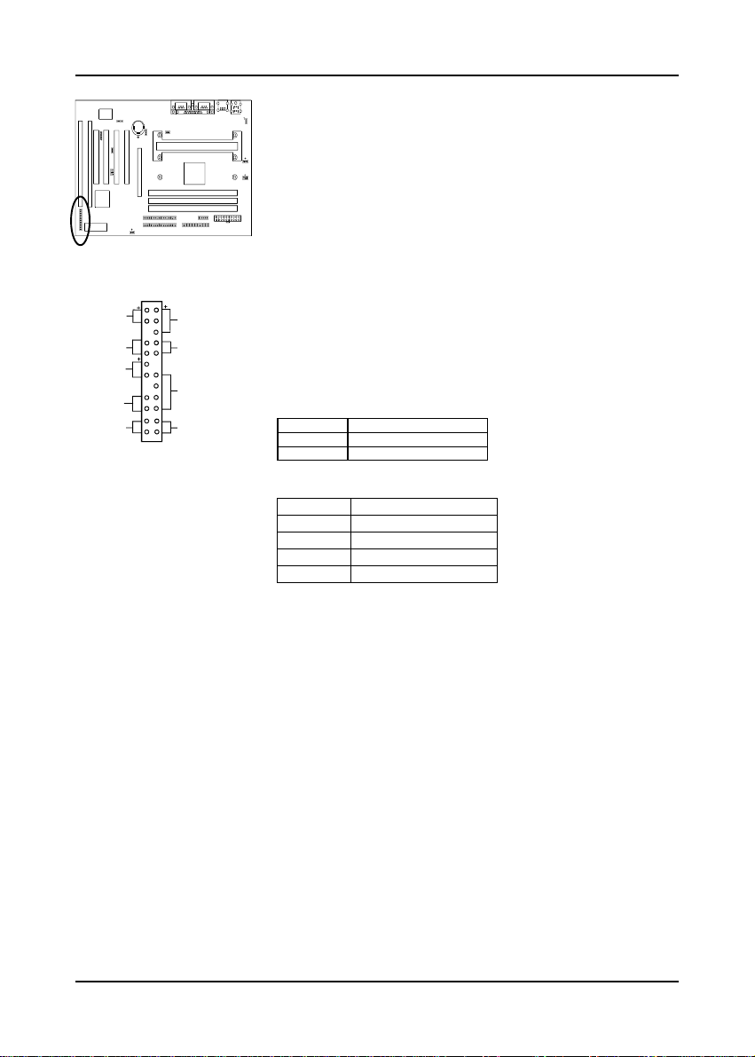
C. Green Switch/Green LED Connector
Some ATX cases provide a Green switch which is used
to put the system in Suspend mode. In Suspend mode,
the power supply to the system is reduced to a trickle,
the CPU clock is stopped, and the CPU core is in it's
minimum power state. The system is woken up whenever
the keyboard or mouse is touched. The system resumes
in different ways as defined by Power Management Setup
screen in BIOS.
T
u
b
r
o
L
E
D
G
e
r
e
n
S
w
itc
h
G
e
r
e
n
L
E
D
e
t
S
w
itc
h
R
e
s
+
v
ity
L
E
D
ID
E
A
c
ti
r
I
n
d
i
c
a
t
o
P
o
w
e
L
o
c
k
K
e
y
p
e
a
k
e
r
H
e
a
d
S
w
e
O
v
e
id
r
-
r
e
P
o
D. System Reset Switch Connector
r
L
E
D
This connector should be connected to the reset switch
on the front panel of the system case. The reset switch
allows you to restart the system without turning the
e
r
power off.
r
B
u
tto
n
Pin Definition
1 System
2 GND
E. Speaker Connector
PIN Definition
1 Speaker Signal
2 NC
3 NC
4 +5V DC
F. IDE Activity LED Connector
The IDE activity LED lights up whenever the system
reads/writes to the IDE devices.
G. Turbo LED Connector
This mainboard does not have a Turbo/De-turbo speed
modes. Even though this function does not exist, the turbo
LED will light when the LED is connected and turbo button
pressed.
Poly-fuse Over Current Protection
The poly-fuse protects the system from dangerous voltages the system might be
exposed to via the keyboard or USB connectors. In case of such exposure, the polyfuse will immediately be disconnected from the circuit, just like a normal fuse. After
being disconnected for a certain period of time, the poly-fuse will return to its normal
state, after which the keyboard or USB can function properly. Unlike conventional
fuses, the poly-fuse does not have to be replaced, relieving the user wasted time and
inconvenience.
13
Page 14
Chapter 2
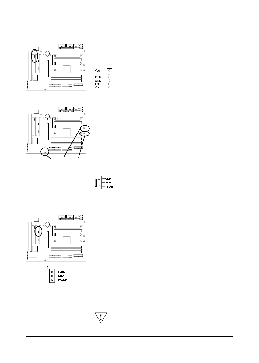
Infrared Connector (CN9)
1
1
1
1
If you enable the COM2 Mode in BIOS's Integrated
Peripherals menu the COM2 port will support IR functions.
(See section 3-7)
1
1
1
1
1
CPU/System1/System2 Cooling Fan Connectors (FAN1/FAN2/FAN3)
1
1
1
1
1
1
1
FAN3
1
1
FAN1 FAN2
These added connectors allow the fan to draw their power
from the mainboard instead of the disk drive connector.
The board's management extension hardware is able to
detect the CPU and system fan speed in rpm (revolutions
per minute). These connectors supports 3-pin cooling
fans with minimum of 3500 RPM. The wiring and plug may
vary depending on the manufacturer. On standard fans,
the red is positive (+12V), the black is ground, and the
yellow wire is the rotation signal.
WOL (Wake-on-LAN) Connector (CN10)
1
1
1
1
1
1
1
1
1
Enable the Wake Up On LAN selection in BIOS's Power
Management Menu to use this function. The capability
to remotely manage PCs on a network is a significant
factor in reducing administrative and ownership costs.
Magic Packet technology is designed to give WOL (Wakeon-LAN) capability to the LAN controller. When a PC
capable of receiving wake up command goes to sleep,
the Magic Packet mode in the LAN controller is enabled.
When the LAN controller receives a Magic Packet frame,
the LAN controller will wake up the PC. This header
is used to connect an add-in NIC (Network Interface Card)
which gives WOL capability to the mainboard.
14
To support this function, a switching power supply
with a minimum of 750mA 5VSB is required.
Page 15
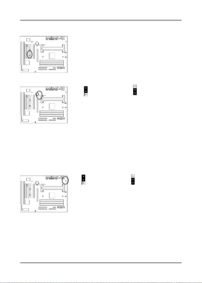
Creative's SB-LINK Sound Connector (JP3)
Hardware Setup
1
1
1
1
1
1
1
1
1
The SB-LINK serves as a bridge between the mainboard
and Creative's PCI sound card. This connector delivers
Sound Blaster 16 compatility for real-mode DOS games.
Clear CMOS Data Jumper (JP4)
11
1
1
1
1
1
1
1
1
1
To clear the contents of the CMOS, please follow the
steps below.
1. Disconnect the system power supply from the power
Normal (default)
source.
2.Set the jumper cap at location 2~3 for 5 seconds, then
set it back to the default position.
3.Connect the system's power and then start the system.
4 .Enter BIOS's CMOS Setup Utility and choose Load
Setup Defaults. Type Y and press enter.
5.Set the system configuration in the Standard CMOS
Setup menu.
Power-on by Keyboard Jumper (JP1)
1 1
1
1
1
This board is able to be turned on by the keyboard (hot
1
key/Password) or mouse click. To use this function,
select a device of your choice at the Power on Function
1
1
1
1
1
option in BIOS's Integrated Peripherals screen (See
section 3-7). You must also set this jumper's cap to pins
2-3 to use this function. Some out-of-date keyboards may
require larger current than supplied by the Suspend 5V
of modern power supplies. When using older keyboards
disable this function.
Disabled (default)
Clear CMOS data
Enabled
15
Page 16
Chapter 2
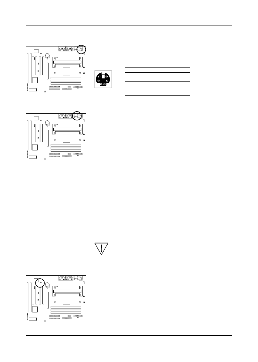
PS/2 Mouse and Keyboard Ports
1
1
1
1
1
1
1
1
1
If a PS/2 mouse is used, BIOS will automatically detect
and assign IRQ12 to the PS/2 mouse.
USB(Universal Serial Bus) Ports
1
1
1
1
1
1
1
1
1
If you want to use a USB keyboard, you must enable the
USB keyboard support function in BIOS's Integrated
Peripherals menu (See Section 3-7). USB is an open
industry standard, providing a simple and inexpensive
way to connect up to 125 devices to a single computer
port. Keyboards, mice, tablets, digitizers, scanners, barcode readers, modems, printers and many more can all be
used at the same time.
USB is a dynamically reconfigurable serial bus with an
elementary data rate of 12Mbps. Based on off the shelf,
low cost micro-controller technology, its modular layered
software protocol supports sophisticated devices and
application programs.
This board contains a USB Host controller and includes
a root hub with two USB ports (meets USB Rev 1.0 spec.).
Two USB peripherals or hub devices are able to be
connected.
Compatibility with different USB peripherals is still
being tested.
Pin Definition
1 Data
2 No Connect
3 Ground
4 +5V (fused)
5 Clock
6 No Connect
Modem
1
1
1
16
Telephony ConnectorTelephony Connector
Telephony Connector(CN22)
Telephony ConnectorTelephony Connector
1
1
1
1
1
1
This connector supports modem telephony input and
mono audio output for modem telephony device.
Page 17
Hardware Setup
m
B
B
2-5 Main Memory Configuration
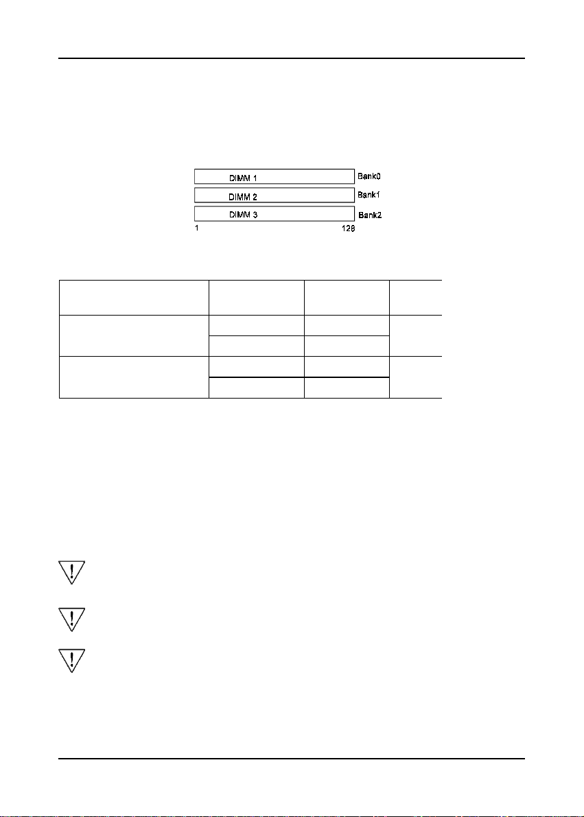
The DRAM memory system consists of three banks and the memory size ranges from
16~384 MBytes. If you only use one bank it does not matter which one you use and
if you use two or more banks, it does not matter which bank you install first.
DRAM Specifications
System Frequency SDRAM Type Max Me
3 unbuffered DIMM Modules
3 Registered DIMM Modules
66MHz 12ns or faster
100MHz 10ns or faster
66MHz 12ns or faster
100MHz 10ns or faster
384M
768M
DIMM type: 3.3V, unbuffered, registered, 64/72-bit Synchronous
DRAM with SPD*
Module size: Single/double-side 16/32/64/128 MBytes
Parity: Either parity or non-parity
The compatibility of 256MB and Registered DIMM is still under testing and
cannot be guaranteed.
This mainboard supports 3.3v, unbuffered, 4-clock, SDRAM DIMM only.
Buffered, 5V, or 2-clock SDRAM DIMMs should not be used.
Due to loading anomalies, using DIMM with an 'n x 4' DRAM base on this
mainboard is not recommended. For example, a DIMM that uses sixteen
16Mb x 4 devices should not be used.
17
Page 18

Chapter 2
SPD (Serial Presence Detect)
This is an EPROM that contains speed and design information about the memory
module. The mainboard queries the module and makes adjustments to system
operation based on what it finds.
ECC DRAM Capability
This mainboard can be configured to support ECC (Error Check and Correct)
function when utilizing parity DIMM modules. To utilize the chipset's ECC
features, you must use a 72-bit DIMM module.These modules are automatically
detected during bootup. However, the user must configure the DRAM Data Integrity
Mode to "ECC" in BIOS's Chipset Features Setup menu to enable the ECC function.
ECC detects double bit errors and detects and corrects single bit memory errors
on the fly without user intervention. Errors may be generated by a defective memory
module, conflicting memory speeds between different banks, DMA, etc.
18
 Loading...