

Chago Wallbox
Installation instruction
ENG
Operation instruction
RAK 111
20.10.2016
1

Contents
1. Chago Wallbox 3
2. Safety Instructions 3
3. Delivery Contains 4
4. Accessories 4
5. Installation instructions 5
5.1. Before Installation 5
5.2. Wall Bracket Installation 6
6. Supply Connection 9
7. Commissioning 10
7.1. Connecting to Chago Wallbox 10
7.2. Congurating to Chago Wallbox 11
7.3. Commissioning Standalone Charging Point 12
7.4. Commissioning Online Charging Point 13
8. User Instructions 15
8.1. User Interfaces 15
8.2. Charging 15
9. Technical Information 16
10. Warranty 17
11. Dimension Drawing 17
12. Installation / Commissioning Checklist 18
13. Maintenance / Preventive Maintenance Instructions 19
14. Troubleshooting 20
15. EVB100 Internal Circuit Example 21
16. EVB200 Internal Circuit Example 22
2
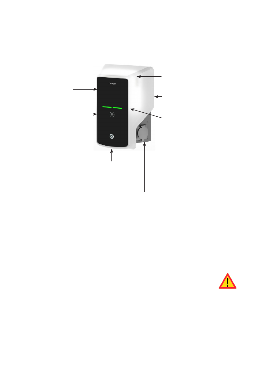
1. Chago Wallbox
EVB100: Single charging unit
EVB200: Dual charging unit
Plastic front
cover
Ambient light
(optional)
Painted steel
frame
RFID reader
Front cover
lock
1-2 x Mode 3/ Type 2 socket outlet
3-color LED
indicates the
charging point’s
status
2. Safety Instructions
• Chago Wallbox must be installed by a qualied person.
• Read this instruction manual before installation and usage of the charging point.
• The instruction manual must be stored in a safe location and be available for future installation and
service.
• Follow the guidelines in the instruction manual when installing and using the charging point.
• The installation must be done according to the local safety regulations, restrictions, dimensioning,
rules and standards.
• The information provided in this manual in no way exempts the user of responsibility to follow all
applicable rules and safety standards.
3
3. Delivery Contains
• Chago Wallbox (EVB100 / EVB200)
• Installation and Operation instruction
• Optionally Wall bracket (EVTL40.00)
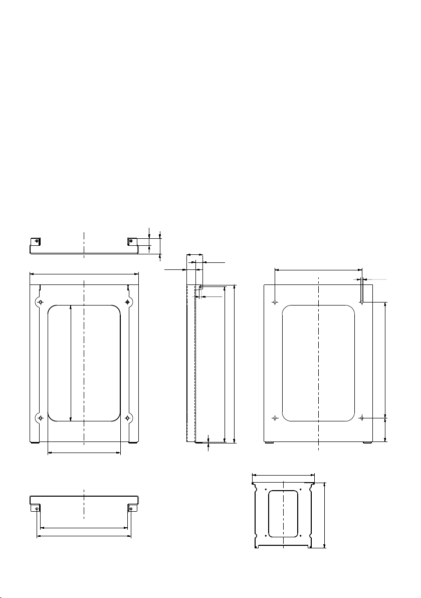
4. Accessories
Wall bracket
EVTL40.00
Included on Wallbox congurations EVBx00-A/-B/-C/-D.
For other congurations please order separately.
20
43
300
45
25
2x Ø6
20
240
4x Ø7
320
241
260
200
436
429
2
431
452,6
320
65
4
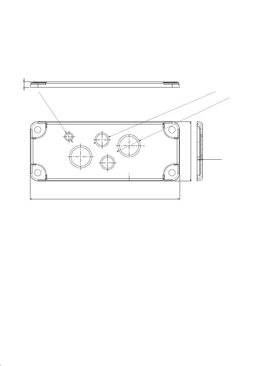
Flange
KOT21715
Included in the delivery.
Note! Cable glands are not included in the delivery.
Please order suitable cable glands separately according to the used supply cable sizes, for example Ensto
KTM... cable gland series (polyamide or brass).
8
Ø12.5 (Knock-out)
Ø20.5 2pcs (Knock-outs)
Ø32.5 2pcs (Knock-outs)
86
216
+0.1
0.7
-0.1
ALL KNOCK-OUTS
5. Installation instructions
5.1. Before Installation
Remove the Wallbox from it’s package. Do not scratch the surface of the Wallbox after removal from the
package.
When selecting installation site, take into accoun the following:
• The minimum space needed for operating and maintenance.
• Make sure that the wall material is suitable and robust. The mounting surface should be at and
vertical.
• In order to ensure the optimal charging performance, the charging unit should not be exposed to
direct sunlight.
5
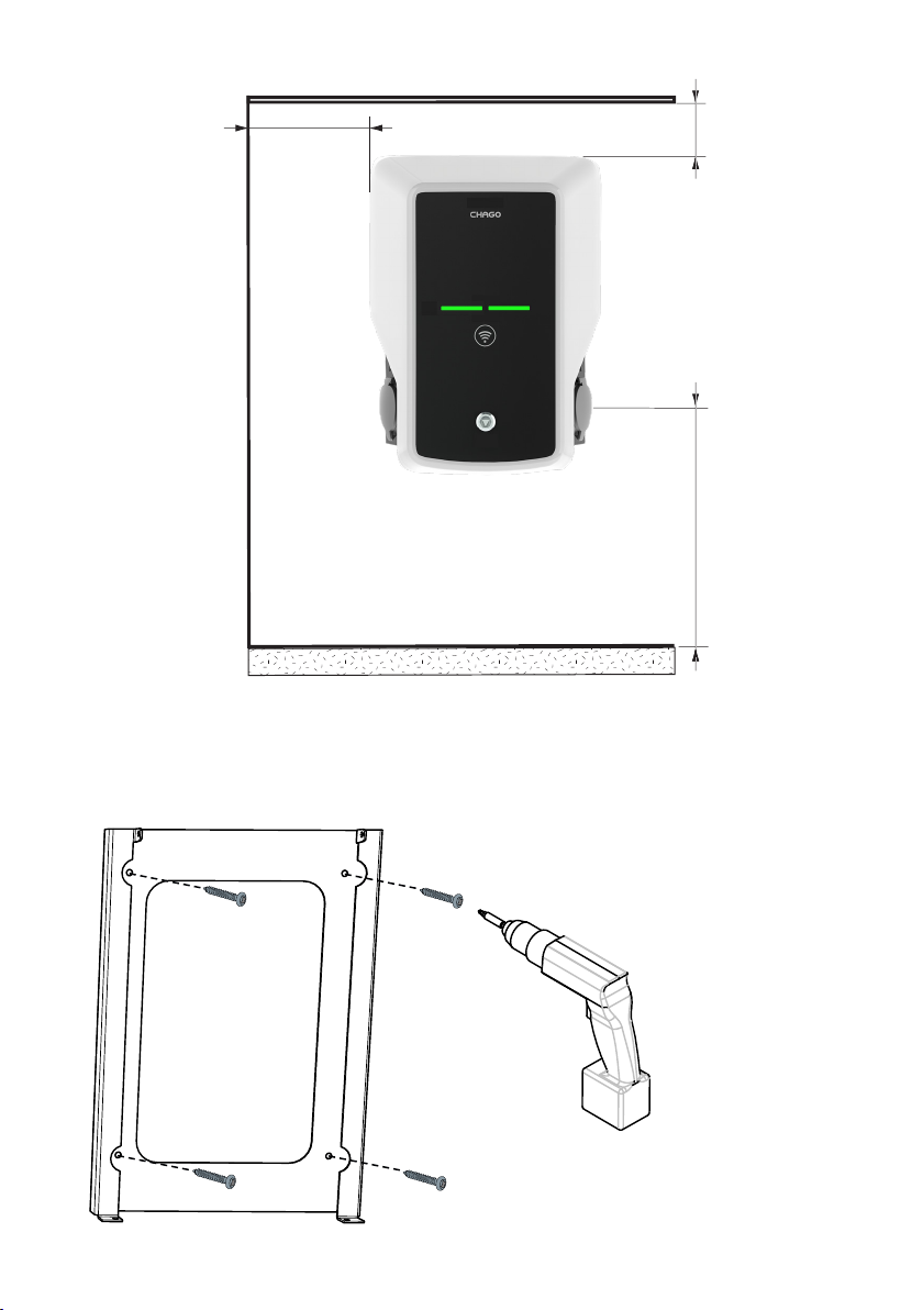
min. 400 mm
min. 200 mm
Recommendation
1200 mm
Follow always national regulations
and site requirements
5.2. Wall Bracket Installation
6
Step 1
• Drill screw holes for the wall
bracket.
• Place the wall bracket on the
wall using suitable screws.
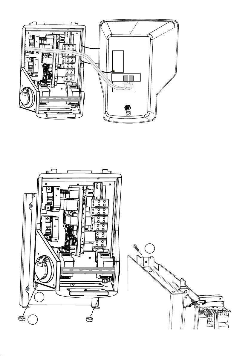
Step 2
• Open the front cover lock
and remove the front cover.
Note! RFID, LED module and 3G
antenna cables are attached to
the front cover. Be careful not to
break any components when you
remove the front cover.
Step 3
• Place the Wallbox on the wall bracket (1).
• Attach the top of the Wallbox on the wall
bracket using the screws included in the
package (2).
• Secure with nuts included in the package (3).
2
1
3
7

Step 4
• Remove the front DIN rail if needed to make more space for the installation work.
• Remove the ange at the bottom of the Wallbox frame.
• Open the knock out needed for the cable gland.
• Put the cable gland in place.
• Put the ange in place.
• Pull the supply cable through the cable gland approx. 600 mm.
• Remove the cable sheath approx. 200 mm measured from the cable gland exit.
• Secure the front DIN rail in place.
• Pull the supply cable leads through the plastic guide included the delivery.
• Run the supply wiring above the DIN rail in such a manner that the outlet locking system is not damaging the supply wires.
• Cut the supply cable leads in dierent lengths. Leave the ground lead long enough so that if a fault
occurs it is the last one that comes loose.
• Strip the leads 25 mm and connect to the supply connectors.
• Ensure that the RFID, LED module and 3G antenna cables are routed correctly.
• Close the front cover.
DC power supply
Controller board / boards
Front DIN rail
8
Supply connectors
Cable route
Plastic guide
Supply cables

6. Supply Connection
The voltage and current ratings including cables and line protector dimensioning must comply with national regulations. System dimensioning must be done by a qualied electrical designer.
Connect separate supply cables for each charging outlet.
Stranded cables are recommended in Wallbox installations.
A Residual current protection device (RCD) and a circuit breaker (MCB) for each charging outlet must be
installed in the switchboard.
Example: Supply connection for Chago Wallbox with 2 outlets
2
F02
L1
L2
L3
2
F01
L1
L2
L3
PE
1
MCB
B6
L1
L2
L3
SUPPLY 2
N
1
MCB
B6
N
PE
L1
L2
L3
SUPPLY 1
N
N
PE
9

7. Commissioning
Before commissioning the Chago Wallbox must be installed according to the installation instructions.
By default all Chago Wallboxes are operating in free charging mode (standalone operation). In this free
charging mode external communication (Ethernet, 2G/3G) is not active. If the Chago Wallbox is going to
be connected to some back-oce (online mode), rst make sure that the basic function ality is working
before establishing communication.
7.1. Connecting to Chago Wallbox
If you want to change the default settings, you must connect to Chago Wallbox via web conguration tool
to be able to proceed with the commissioning settings. Use Firefox or Windows Explorer web-browser for
conguring.
EVB100
micro USB service port
micro USB --- USB cable
PCEVB
EVB200
micro USB service port
10
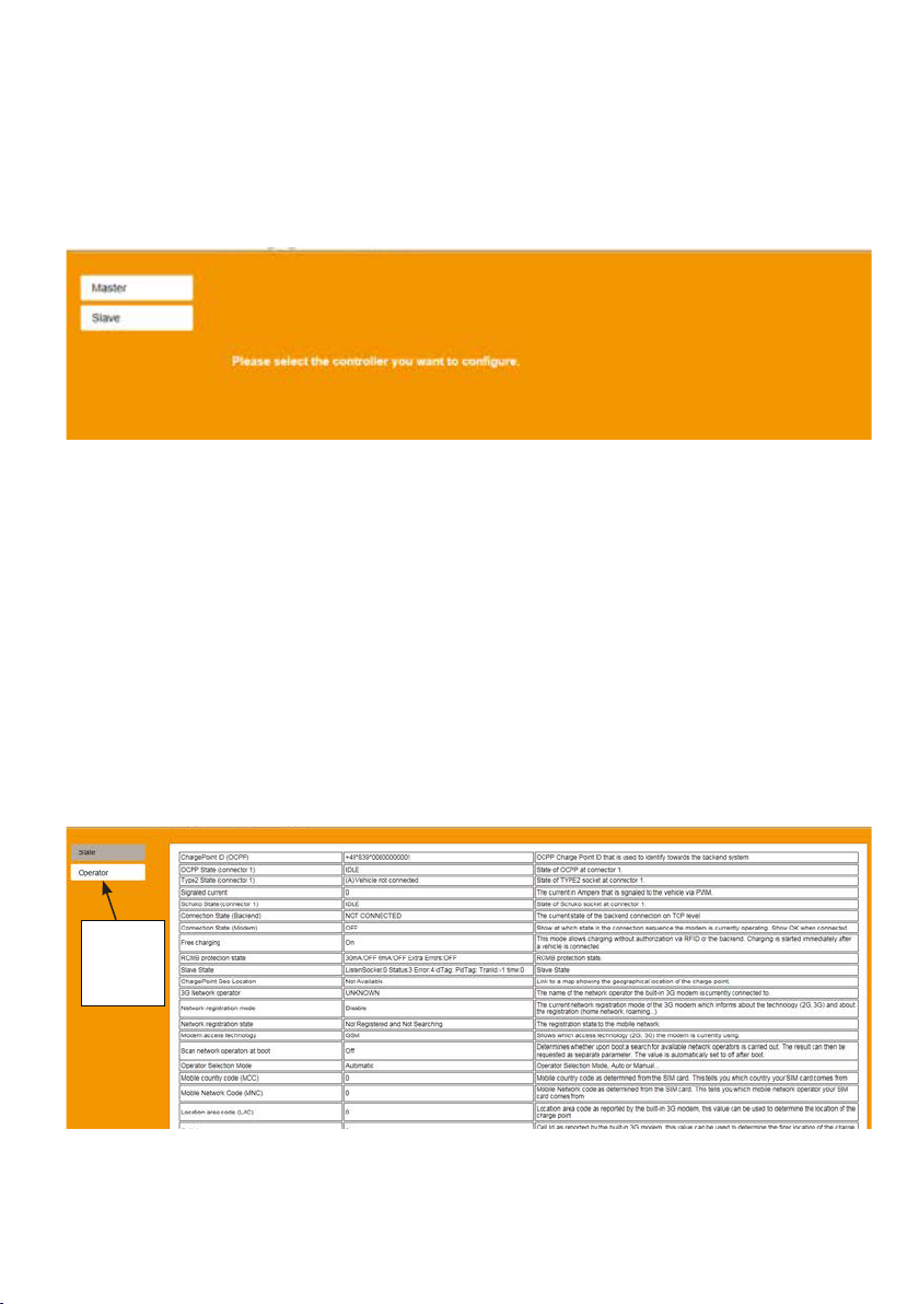
7.2. Congurating to Chago Wallbox
1. If you want to see device status, and settings, login as viewer.
Go to: http://192.168.123.123/
Login page opens, select “Master” or “Slave” controller to review settings.
2. If you want to make changes, login as operator.
Connect to SLAVE controller.
Go to: http://192.168.123.123/operator
Connect to MASTER controller.
Go to: http://192.168.123.123:81/operator
When operator selection is visible you can make changes to connection setting (OCPP, Ethernet, 3G
modem etc.)
When browser asks for username and password, enter the following:
User name = operator
Password = yellow_zone
Operator
selection
visible
11

7.3. Commissioning Standalone Charging Point
1.a) Free Charging
By default “Free Charging” is on. Charging starts immediately after a vehicle is connected. Authorization
using a RFID tag or via backend is not in use.
1. Open the front cover.
2. Switch F01 / F02 ON.
3. Ensure that the DC power supply turns on (green LED).
4. Wait until front cover LED turns from red to green.
Note! The startup takes approx. 1 - 2 minutes.
5. The unit is ready for use in “Free charging” mode.
Note! By default the maximum charging current is 32 A. The maximum charging current can be changed.
Login to the charging point and enter the new maximum current with parameter “Operator Current Limit
(A)”. Apply changes to Master and Slave controllers separately. See chapter 7.1 and 7.2 for details.
Note! Supply phase conguration. By default the charging point is congured with 3-phase supply. In case
of 1-phase supply, change the phase conguration. Login to the charging point and enter the existing
phase parameter “Phases connected to the Charge Point”. Apply changes to Master and Slave controllers
separately. See chapter 7.1 and 7.2 for details.
1.b) Authorized charging
Charging starts when showing RFID tag to the RFID reader.
1. Open the front cover.
2. Switch F01 / F02 ON.
3. Ensure that the DC power supply turns on (green LED).
4. Wait until the front cover LED turns from red to green.
Note! The startup takes approx. 1 - 2 minutes.
5. Connect your service laptop to Wallbox by using a micro-USB service port on the controller board.
6. Log in http://192.168.123.123:81/operator.
7. Select “Free charging” mode o.
12

8. Add RFID ID’s on the internal memory of the charging point:
Note: List of colon-separated IDs for the cache. A maximum of 80 entries are shown. To clear the
cache, the list must be empty. The listed IDs are added, while the other cache entries are not deleted.
See the examples below.
9. When ready, click “Save & Restart” to active the new settings.
10. Wait until the front cover LED turns to green.
11. Close the front cover.
7.4. Commissioning Online Charging Point
2.a) Congurating Ethernet operation
1. Open the front cover.
2. Switch F01 / F02 ON.
3. Ensure that the DC power supply turns on (green LED).
4. Wait until front cover LED turns from red to green.
Note! The startup takes approx. 1 - 2 minutes.
5. Connect your service laptop to Wallbox by using micro-USB service port.
6. Log in http://192.168.123.123:81/operator
7. In order to set the unit to online mode the following settings must be activated:
Back-end connection settings:
◊ Charging point ID (OCPP), by default serial number of the controller (master / slave)
◊ Connection type, select “Ethernet”
◊ OCPP mode (depends on the communication protocol the connected back-end supports)
◊ SOAP / JSON OCPP URL (back-end connection address), select SOAP or JSON based on used
OCPP mode
Ethernet connection settings:
◊ DHCP in use
8. When ready, click “Save & Restart” to active the new settings.
9. Wait until the front cover LED turns to green.
10. Ensure that the set charging point ID is visible at the used back-end system.
11. Close the front cover.
13

2.b) Congurating 3G Operation
One “micro-SIM” card is needed per Wallbox unit.
“Micro-SIM” card
If you need to remove the “micro-SIM” card,
pull the white tape which is attached on
the rear side of the card.
1. Open the front cover.
2. Switch F01 / F02 ON.
3. Ensure that the DC power supply turns on (green LED).
4. Wait until front cover LED turns from red to green.
Note! The startup takes approx. 1 - 2 minutes.
5. Connect your service laptop to Wallbox by using micro-USB service port.
6. Log in http://192.168.123.123:81/operator
7. In order to set the unit to online mode the following settings must be activated:
Back-end connection settings:
◊ Charging point ID (OCPP), by default serial number of the controller (master / slave)
◊ Connection type, select “3G”
◊ OCPP mode (depends on the communication protocol the connected back-end supports)
◊ SOAP / JSON OCPP URL (back-end connection address), select SOAP or JSON based on used
OCPP mode
3G modem settings:
◊ APN name (operator dependent)
◊ APN username / password (if in use)
◊ SIM card PIN number (if NoPin version)
8. When ready, click “Save & Restart” to active the new settings.
9. Wait until the front cover LED turns to green.
10. Ensure that the set charging point ID is visible at the used back-end system.
11. Close the front cover.
14

8. User Instructions
8.1. User Interfaces
LED signal lights will show the status of the charging point as described below:
Charging point status
Charging point free and ready to use
RFID read, user login ongoing
User login fail, access denied
User loggin passed, charging allowed
While connecting the cable
Vehicle connected, charging not started
Vehicle connected, starts charging
Charging ongoing
Error state
LED light LED operation
Green Stable
Green Flashing
Red Stable
Green Waving
Green Flashing twice
Green Waving
Blue Waving
Blue Stable
Red Stable
8.2. Charging
Free charging
• Plug in your electric vehicle to start charging.
• Unplug your electric vehicle to stop charging.
Charging with RFID
You must have an RFID tag which has a permission to access the charging point.
Start Charging with RFID
• When the charging point is free and the indicator light shows green, you can start a charging event.
• Show the RFID tag to the RFID reading area.
• When the RFID tag is read, the charging point will ash green and verify the user permission to
charge. If the user login is failed, the indicator light turns to red. If the user login is passed, the indicator light turns to waving green.
• Now you are logged in to the charging station.
• Plug in the electric vehicle for charging. The indicator light turns to stable blue.
Stop Charging with RFID
• Show the RFID tag to the RFID reading area.
• When you stop the charging event, the indicator light turns to waving green and you are able to
unplug the charging cable.
• After you have unplugged, you are logged out from the charging point and the charging point is
free for the next user.
15
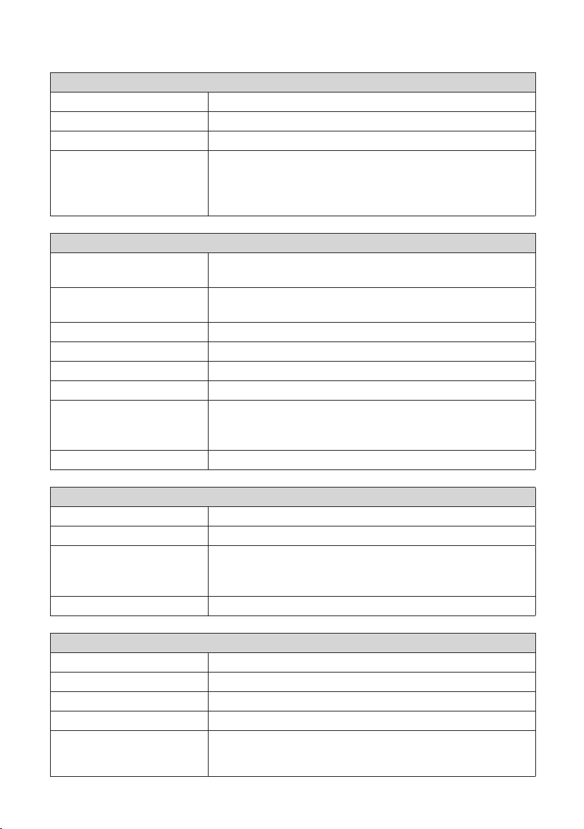
9. Technical Information
Electrical Connections
Nominal supply voltage 1-ph/3-ph, 230/400VAC, 50Hz
Charging current (nominal) 3x32A, congurable between 6A…32A
Charging power (nominal) Max. 22kW per charging outlet
Supply connections and
terminals
Design and Mechanics
Materials Frame: Painted steel frame
Color Frame: Painted steel frame (RAL7021 “Anthracite”)
Weight approx. 10 kg, depends on product conguration
IP class IP54
IK class IK10
Operating temperature -30 C…+50 C
Standards IEC 61851-1
Approvals / markings CE
L1, L2, L3, N, PE
Cu 2.5–50 mm, Al 6–50 mm
Recommended 10 mm at nominal power
Tightening torque Nm: 4 Nm (2.5 - 4 mm²), 12 Nm (6 - 50 mm²)
Cover: Plastic
Cover: White plastic and black tape
IEC 62196-2 (socket outlets/plugs)
IEC 61439-1:2011
User Interface
Socket outlet Mode 3 / Type 2 or Mode 3
Charging status indication 3-color LED (Green/Ready, Blue/Charging, Red/Error)
Use access RFID (ISO/IEC 14443A, ISO/IEC 15693)
Free access
Mobile apps via 3rd party operators
Current measurement Integrated/on-board measurement
Safety Features
RCMB On-board: RCMB (6mA DC residual current detection)
RCD To be located to distribution board (at least type A, 30mA)
MCB To be located to distribution board (class C, nominal current 32A)
Control voltage 12VDC
Temperature control High operating temperature, such as direct sunlight, can cause
reduced charging current or temporary interruption in the charging
procedure
16
Control and Communication
Operation mode Standalone/Online
Wireless 2G/3G
Wired Ethernet
Protocol OCPP1.5 or OCPP1.6
10. Warranty
Warranty conditions, see www.chago.com.
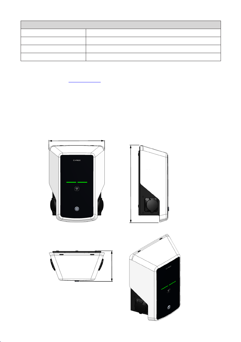
11. Dimension Drawing
348
481
191
17
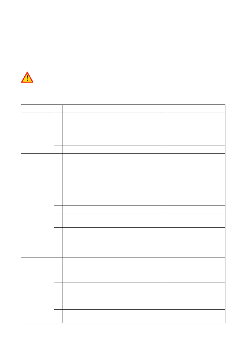
12. Installation / Commissioning Checklist
Introduction
This checklist is a guidance for ensuring both mechanical and electrical installation as well as commissioning of the Chago Wallbox.
Before Installation
Read the product specic installation instructions before performing any actions.
Note! Only trained electrician may perform the installation in accordance with the applicable local and national electrical rules and standards.
Checking the Installation
Go through the visual, mechanical and electrical installation when the charging point is un-powered.
CATEGORY X ITEM NOTES
Overall look Ordered material has been received.
Protective plastic wrapping have been removed.
No scratches or damages may be seen.
Mechanical
installation
Electrical
installation
Operational
check
Charging point is xed properly on the wall.
The front cover opens and closes smoothly.
Charging point’s power supply capacity meets
electrical planning (cable size, MCB…).
Gently push the charging point with a hand to
create vibration to ensure no bad contact / connection exist (wire or PCB).
Gently push the controller to create vibration to
ensure no bad contact / connection exist (wire or
PCB).
Check tightness of the PE-cable screw.
Power supply cables (L1, L2, L3, N and PE) are
properly connected.
Insulation of power supply cables is intact (L1, L2,
L3, N and PE)
Voltage between PE and N is less than 10 V
PE quality is less than 3
All the LED states / color (green, blue, red) and RFID
reader is functioning.
Available electricity at the sockets. All the contacts
(L1, L2, L3) must be tested.
Verify that when charging point LED is green, there
is no power at the socket contact (L1, L2, L3, N).
With Mode 3 tester, test the functioning of Mode 3
(from green to blue).
Review local electrical
design plan.
Create fail and charge (with
RFID tag). Red at bootup,
green at idle and blue while
charging.
Use Mode 3 tester.
18

Ready for use Correct SW in use
Correct operating mode
• Standalone
• Online
13. Maintenance / Preventive Maintenance Instructions
1 x per year
WARNING! Danger of electrical shock or injury.
Disconnect power before working inside the device or removing any components.
X MAINTENANCE ACTION
Retighten all screws (electric components).
Check the Mode 3 socket and if needed change it (burn or parts damage) (socket cost not under
warranty).
Check the charging cable and if needed change it.
Check the sealings.
Gently push the charging point with a hand to create vibration to ensure no bad contact / connection exist (wire or PCB).
Gently push the controller to create vibration to ensure no bad contact / connection exist (wire or
PCB).
Create fail and charge (with RFID card) to check all the LED states / color (green, blue, red) and RFID
reader is functioning.
Test available electricity at the sockets; use Mode 3 tester if needed. All the contacts (L1, L2, L3 must
be tested).
With Mode 3 tester, test the functioning of Mode 3 (from green to blue).
Check tightness of the PE-cable screw.
Test voltage between PE and N (must be less than 10 V).
Test PE quality (must be less than 3 ).
SW update if needed (if in service contract).
Restart the station from F0, ensure it will restart properly.
19

14. Troubleshooting
Charging station is o, no lights on
Issue Corrective action
Mains voltage does not exist in supply connector L1.
Circuit breaker F0 is o. Turn F0 on.
12V power unit has no LED on. Ensure 230V power supply to 12V power unit; if ok re-
The controller has no PWR LED on. Ensure power supply to the controller; if ok replace the
Charging cable is locked in Mode 3 socket outlet
Issue Corrective action
Unexpected fault has occurred while power is
on.
Power is o. Open the front cover. Switch Mode 3 lock into open
Ensure proper power supply.
place the power unit.
controller.
Option 1:
If equipped with Mode 3 lock release functionality,
turn o the power from F0 and pull charging cable
out from the socket.
Option 2:
Turn o the power. Switch Mode 3 lock manually into
open position.
position. Note! If the station has a Mode 3 Lock
Release functionality, then during power cut the
Mode 3 lock opens automatically.
Conguration via web browser
Issue Corrective action
PC does not recognize micro USB plug and connection to the controller cannot be established
via web browser.
Check from Windows 7 / 10 operating system settings
via “Device Manager” that RNDIS network adapter is
available. If not, update the related Windows driver.
20
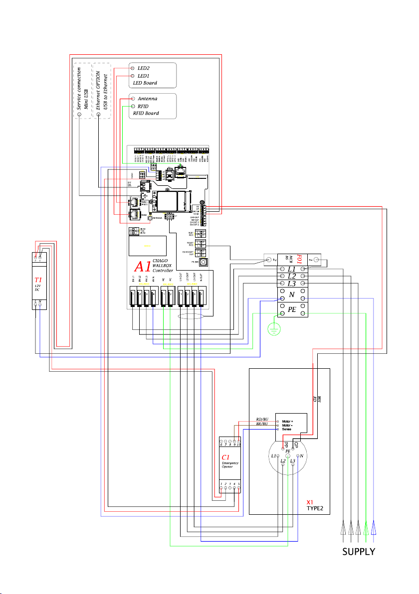
15. EVB100 Internal Circuit Example
21

16. EVB200 Internal Circuit Example
22

23

Ensto Chago Oy
Kipinätie 1, P.O. Box 77
FIN-06101 Porvoo, Finland
Tel. +358 20 47 621
Customer service: chago.support@ensto.com
chago.support@ensto.com
www.ensto.com
 Loading...