


CHALLENGER
Open Flue Boilers
30 OF
(GCN"41.980.72)
50 OF
(GCN"41.980.76)
installation
and servicing instructions
(leave these instructions with the User or at the Gas Service meter)

CHALLENGER OF are low water content gas fired boilers.
CHALLENGER
30 is rated between 4.14 Kw (14,150
Btu/h) and 9 Kw (30,375 Btu/h).
CHALLENGER
50 is rated between 7.33 Kw (25,000
Btu/h) and 14.6 Kw (50,000 Btu/h).
The boiler is designed for use on Natural Gas, unless
otherwise stated. It is suitable for open systems and sealed systems.
The boiler is designed for fully pumped systems only with
a number of incorporated features.
- Fully adjustable electronic temperature regulation between60°Cand82”C.
- Automatic alternation high flame/low flame.
- Pump overrun.
- Low resistance.
- High limit thermostat.
Guarantee
The manufacturer’s guarantee on the appliance is for 24 months from the date of installation. The guarantee is voidable if it is
not installed in accordance with the recommendations made herein or in a manner approved by the manufacturer.
1.
TECHNICAL DATA
V
+=++
- _
-A-
I- i
-7-
A
F
-I+
A+ I --+-
-+-
E
I
CHA
ENCER 3C
-
-
I
-
mm
A
640
B
375
C
250 9.84
D
115
E
100
F
50
45 1.75
ci
H
187
475 10.7
J
K
500
L
135 5.3
M
25
N
100
50 2.0
0
(int)
=-50
ins
25.2
14.75
4.5
4.0
2.0
7.4
19.7
1.0
4.0
OF
2

1.2
30 OF
OUTPUT
INPUT BURNER PRESSURE (HOT)
GAS RATE
1.3
kW Btu/h
Max
Min
50 OF
Max
Min
DIMENSIONS
I
9. 30,375
4.14 14,150
OUTPUT
kW Btu/h
14.6 50,000
7.32 25,000
(Casing ex connections)
3OOF&5OOF
mm
I
Max 11.7 39,995 8.0 3.2
Min 5.63 19,226 1.47 0.5
Max 18.94 64,661 7.3 2.9
Min 9.95 33,800 1.9 0.08
NB
ins
Openflue . . . . . . . . . . . .
Gas connection .......................
Waterconnection .....................
Minimum flow rate ....................
Maximum static head .................
Minimum static head ..................
Electrical connection ..................
Weight ..............................
Water capacity .......................
Burner Injector Size ...................
Pilot injector .........................
Ignition ..............................
Electrode ............................
Boiler thermostat .....................
High Limit thermostat .................
Thermocouple and thermoelectric valve
kW Btu/h m.bar
INPUT BURNER PRESSURE (HOT)
kW Btu/h m-bar
: For mid position setting pressures see section 5.4
I
Requires a nominal 100 mm (4 in) flue pipe. Draught diverter is intergral
and is suitable for flues to BS 715. If flues to BS 567 are used an adaptor
will be required
15 mm compression fitting
22 mm compression fittings
30
OF
505 IiWhr (I .85 gpm) 50
15” C (27” F) temperature rise
30 m (98 ft)
150 mm (See page 7)
240 V single phase 50 hz supply fused 3 amp
30
OF -
18.63 kg (41 Ibs)
0.5 lit. (0.11 gals.)
30
OF
1.18 mm
50
OF
1.23 mm
0.3 mm (0.011 ins.)
Continuous spark-spark generator ANSTOSS
Chaffoteaux - spark gap 5.0 mm
Electronic - Chaffoteaux Ltd
Ranco LM5
Chaffoteaux Ltd
ins.w.g.
ins.w.g.
Sides
TOP
Bottom
Front
OF
841 lit/hr (8.08 gpm) equivalent to
50
OF -
19.54 kg (43 Ibs)
m3/h ft3/h
1.09 38.67
0.52 18.59
GAS RATE
m3/h ft3/h
1.77 62.53
0.88 31.39
CLEARANCES
mm ins
76 3
76 3
127
500 20
5
1.4
HYDRAULIC RESISTANCE
The hydraulic resistance of the boiler varies with
the water flow. The graph (Fig. 2) indicates resistance at various flow rates.
The minimum flow rate is equivalent to a temperature rise of 15” C :
30
OF
505 I/h 1.85 gpm 841 I/h 3.08
Minimum water flow rate *
50
OF 9 a
gpm
water flow-gallons per minute
1
200 400 600 800 mob
3
2 3 4 5
water flow - litres per hour
1200 1400
3
1
2'
.I
B
d
1

1.5 Description of Operation
Pressing the ignitor (on) button disconnects the supply continues to fire on 50 % fixed gas valve. When the set
to the pump, opens the therm0 electric valve and causes temperature is reached the boiler switches off. If flow
a continuous pilot ignition spark to be generated and the temperature reduces the 50 % fixed gas valve opens folpilot is ignited. lowed by the variable valve.
If there is a demand the pump will start when the on
button is released. The burner will commence after a 30
sec. delay when the 50 % valve opens. After 3 seconds
the 2nd gas valve (variable output) opens.
Temperature control is by means of a temperature sensing thermistor and potentiometer. These signals are
fed to a comparitor.
When the flow temperature approaches the set temperature the main gas valve is closed and the boiler
At the end of an ‘on’ cycle under the control of a time
clock or programmer or when the cylinder and room
thermostat are satisfied the boiler switches off but the
pump continues to run for 15 seconds.
The high temperature cut out breaks the thermocouple
circuit which extinguishes the pilot and closes the gas
supply to the burner. Manual re-setting is required. (See
section 4.7).
FUNCTIONAL FLOW DIAGRAM
Fig. 1
THERM0 ELECTRIC
TIME DELAY PUMP
OVER RUN
SPARKGENERATOR
THERMOCOUPLE
TIME DELAY
GAS SOLENOID
L
r
PUMP
INSTALLATION REQUIREMENTS
2.
2.1
General
The installation of the boiler must be in accordance with
the Gas Safety Regulations, Building Regulations, I.E.E.
Regulations and the Byelaws of the local Water Underta-
king. It should be in accordance also with BS Codes of
Practice and the British Gas Specifications for Domestic
Wet Central Heating Systems and any relevant require-
ments of the local Gas Region and Local Authority.
Detailed recommendations are stated in the following
British Standard Codes of Practice : CP 331:3, BS 5376:2,
BS 5546, BS 544O:l and 2, BS 5449:l.
Note : Gas safety (Installation and Use) regulations 1984 :
It is the law that all gas appliances are installed by competent persons in accordance with the above regula-
tions Failure to install appliances correctly could lead to
prosecution, It is in your own interest and that of safety
to ensure compliance with the law.
2.2 Location
The position chosen for the boiler should permit the pro-
vision of a satisfactory flue termination. The position
should also provide adequate space for servicing and air
circulation around the boiler. (See 1.3).
Where installation will be in an unusual position, special
procedures may be necessary, and BS 5376:2 gives de-
tailed guidance on this aspect.
A cupboard or compartment used to enclose the boiler
mtrst be designed and constructed specifically for this
purpose. An existing cupboard or compartment may be
used provided that it is modified for the purpose.
Details of essential features of cupboard/compartment
design are given in BS 5376:2.
4

2.3 Water Circulation Systems
Open or sealed type central heating systems (see Section
5) should be in accordance with the relevant recommendations given in BS 5376:2, BS 5449:l (for smallbore or
microbore systems) and the British Gas Specifications
for Domestic Wet Central Heating Systems.
Hot water systems should be in accordance with the relevant recommendations given in CP 342:l and the above mentioned British Gas publication and BS 5546.
2.4 Air supply - Open Flue Version
2Al
2A.2
Room air supply
Where a boiler is to be installed in a room or internal space, the boiler requires the room or internal space containing it to have a permanent air vent. This vent must be
either direct to outside air or to an adjacent room or internal space which must itself have a permanent air vent
of at least the same size direct to outside air.
The minimum effective area of the permanent air
vent(s) is related to the maximum rated input of the boiler and should be not less than :
CHALLENGER 30 OF
CHALLENGER 50 OF 53.73
21.15 cm2 (3.27 ins21
cm2 (8.32 ins?
Compartment air supply
If an open flued boiler is installed in a cupboard or compartment permanent air vents are reauired in accordance with the following table.
Note that both air vents must communicate with the
same room or internal space. and must both be on the
same wall to outside air.
Where cupboard or compartment vents communicate
with a room or internal space the room or internal space
must itself have a permanent air vent(s) as specified in
BS5440 pt2.
An open flued appliance must not be installed in a
bathroom bedroom or bedsitting room or in a compartment communicating with a bathroom, bedroom or bed
sitting room. An open flued boiler must not be installed
in a garage.
Cupboard or compartment air supply
30
OF
2.5
Flue System
The boiler should be sited such that the maximum possible length of the flue system can be contained within the
building and that the route of the flue rises continuously
to the terminal and is as direct as practicable.
The first 600 mm (2ft) of flue pipe should rise vertically
from the draught diverter connection before the use of
any bends of elbows.
Horizontal or shallow angle runs, right angled bends or
mitred elbows should be avoided.
Where an existing brick chimney is to be used it should
be swept thoroughly before connection of the new boiler, and the chimney should be lined.
An approved British Gas terminal must be fitted and the
terminal sited at the.adjacent roof edge and, where pos-
sible, above the ridge line. The flue must not be termina-
ted at or adjacent to a wall face.
The cross sectional area of the flue must not be less
than the area of the flue. outlet serving the boiler. The
point of termination must not be within 600 mm (2 ft) of
an openable window, air vent or other ventilation ope-
ning.
Before installing the boiler to an existing flue system,
the flue system must be checked by applying a smoke
match to the opening at the base of the flue system.
The flue pipe must not be closer than 25 mm (I ins) to
combustible material. For twin walled flue. pipe the
25 mm (I in) distance is measured from the internal pipe.
2.6 Electrical Supply
This appliance must be earthed. All wiring must conform
to the I.E.E. Regulations. The CHALLENGER requires a
240 V single phase, 50 Hz
must be provided adjacent to the boiler, this should preferably be an unswtiched plug and socket. Alternatively a
double pole isolator having a contact separation of at
least 3 mm on both poles must be used. The fuse rating
should be 3 amp. The supply cord must be 0.74 m2 three
core heat resisting cable.
2.7 Gas Supply
The
CHALLENGER
CHALLENGER
of natural gas. The meter and supply pipes must be capable of delivering this quantity of gas in addition to the
demand from any other appliances in the house.
The complete installation must be tested for soundness
as described in CP 331:3
30 requires 1.09 m3/h 38.67 ft3/h.
50 requires 1.77 m3/h 62.53 ft3/h
supply.
A means of isolation
Low level
50
OF
Position of
air vents
211 cm2 106 cm2
32 ins2 16 ins2
Air from room Air direct
or internal space from outside
2A3 Effect of an extract fan
If there is any type of extract fan fitted in the premises
there is the possibility that if adequate air inlet area
from the outside is not provided, spillage of the products from the boiler flue could occur when the extract
fan is operating. Where such installations occur a spillage
test as detailed in BS5440:l must be carried out and any
necessary action taken.
Fig. 2
5

3.
3.1
3.2
3.3
3.4
SYSTEM GUIDANCE
General
The CHALLENGER is a low water content boiler designed
ONLY for use with fully pumped systems. It may be used
with open or sealed systems, all safety controls excluding the pressure relief valve being incorporated in the
boiler. The thermostat is adjustable and, on its maximum
setting, gives a nominal 82 “C (180 “F) ?4 “C (7 “F).
Detailed recommendations for the water circulation are
given in BS 5376.2 19876, BS 5449.1 1977 and BS
5546:1979.
Thermostatic control should be fitted to the cylinder and
heating circuits.
Strainers
Where the CHALLENGER is used as a replacement for a
boiler on an existing system, ideally the system should
be flushed and cleaned using a suitable chemical cleaner
following the manufacturer’s recommendations and fitted with a strainer similar to that manufactured by
Honeywell.
Control Schemes
The boiler is electrically controlled.
Most normal pumped primary control schemes can be
used including thermostatic radiator and cylinder valves.
When using motorised valves the controls should be so
arranged to switch off the boiler when circuits are satisfied.
Chaffoteaux can be consulted where technical assistance is required.
Circulation Pump
The system circulating pump should be sized relative to
the resistance of the connected load and the system design nt selected. The mass flow rate through the boiler
should not be less than that stated in section 1.4. The
pump must be installed between isolating valves. Most
pump manufacturers require a minimum static head on
the pump inlet to prevent cavitation. For boiler resistance see graph on page 3. (Sect. 1.4).
3.8
3.9
3.10
type to BS 1566 Pt. 1. Single. feed cylinders are not suitable for use with the appliance. Flow and return pipework
to the cylinder should be in 22 mm pipe.
Feed and Expansion Tank
The feed and expansion tank should be adequately sized
to accept the system water expansion, it should not be
mounted closer than 9 in. to a ceiling to allow access to
the ball valve.
Inhibitors
Chaffoteaux Limited do not generally recommend the
inclusion of an inhibitor with heating and hot water systems, utilising CHAFFOTEAUX boilers. It is, however, appreciated that the use of a corrosion and limescale inhibitor may be desireable or specified.
The following are the appliance manufacturer recommendations :
Use only a British Gas or similar approved inhibitor
from the Fernox range manufactured by Industrial
(Anti-Corrosion) Services, Brittanica Works, Arkesdon
Road, Clabering, Nr Saffron Waldon.
Use only the quantities specified by the inhibitor
manufacturer.
Cleanse the system as may be required be the inhibi-
tor manufacturer.
Add inhibitor only after flushing when finally refilling
the system.
Add on devices
This appliance is approved by British Gas for safety and
performance. It is important that no external control devices - eg. flue dampers, economisers etc. - be directly
connected to this appliance. unless covered by these Installation Instructions or agreed by the Manufacturer in
writing.
Any direct connection of a control device not approved
by the manufacturer could invalidate British Gas approval and also infringe the Gas Safety Regulations.
3.5
3.6
3.7
Cold feeds and open vents
The cold feed and open vent should be so positioned
that pumping over and sub-atmospheric pressures are
avoided. Recommendations for various layouts are given
on page 7.
The connection should be so arranged that there is a low
velocity point at the open vent junction with the system.
Automatic Air Separator
Chaffoteaux Limited strongly recommend the inclusion
of a British Gas accepted automatic air separator in the
system as shown in fig. 9.
The open vent pipe should rise continuously from the
system pipework.
It should not be entered horizontally into the system pipework. The use of an enlarged T to create a low velocity
point is recommended. The preferred arrangement is
shown in fig. 9.
Cylinder
The domestic hot water cylinder used with the
CHALLENGER must be of the indirect and high recovery
6
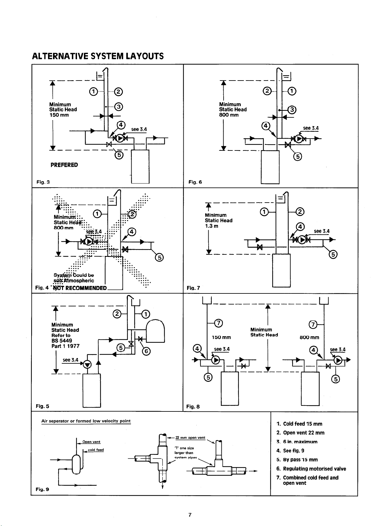
ALTERNATIVE SYSTEM LAYOUTS
Minimum
Static Head
150mm
-----
PREFERED
Syfi &Ad be
sQKWmospheric
. . . . .
Minimum
Static Head
Refer to
BS 5449
Part 1 1977
----.
1. Cold feed 15 mm

3.11 Electrical Controls
Khaffoteaux recommendations)
CHALLENGER can be used with most normal pumped pri-
mary schemes including non-electrical heating and hot
water controls.
It is not normally possible to use full programming facilities where using a mixture of electrical and non-electrical
controls. However, some non-electrical controls are now
available with an external microswitch and these controls
are preferred.
Where the thermostatic radiator valves are used a system by pass will be necessary to maintain the minimum
flow rate - See section 1.4.
Important:
must be in accordance with the current edition of the
IEE Wiring Regulations.
1. Fully pumped system independant control of central heating and hot water using two spring return motorised valves.
All external wiring to and from the boiler
CYL STAT YALYE D.H.W.
SPRING RETURN
3. Drayton flow share valve system.
Fig. 12
4. Honeywell Sundial ‘Y’ plan.
Fig. 10
2. Fully pumped systems independant control of central
heating and hot water using two motorised valves.
PROGRAMMER
Fig. 11
PUMP
BOILER TERMINALS
Fig. 13
5. Satchwell Duoflow system.
TLX 2259
ROOM
PROGRAMMER
Fig. 14
SA 2457
PUMP
RO,,.ER TERMINALS
a

4.
INSTALLING THE BOILER
A vertical flat area is required for the boiler as follows :
525 mm wide x 865 mm high (21 ins x 34 ins)
The above dimensions include the necessary clearances around the boilers for case removal and for air movement.
4.1
4.2
4.3
Position the boiler
- Using dimensions on page 2 mark position of fixings
for top wall bracket (A).
- ;I;,and plug wall and fix bracket using screw provi-
- Ensure applaince is square on wall.
- Mark bottom fixing holes (B). Drill and plug the wall
and fix appliance.
IMPORTANT NCTTJCE : Tl$ulBER ~FRAMED HOUSES
If the appliance is to be fitted in a timber framed building it shotid beWted in accordance with the British GasPublication (( Guide for&s Installations in Timber Framed Housincj a) reference DM 2.lf in doubt. advice must be sought from
the local Gas N&n of British Gas.
‘Fitting -the boiler
a) Remove the front case by
1. .Remov@g 2 screws bottom rear of boiler (Al.
2. Removing 2 screws securing front casing to electrical box CBI.
b) Remove case by putting out at the bottom and lifting
off locating hooks at the top of boiler.
4.4
Making the gas connection
a) Fit the gas service tap (Al together with the filter
washer.
b) The gas supply pipe. size should be sufficient to ensu-
re that there is 20 mbar (8 in.w.g.) pressure. at the
service tap, with the appliance working.
n.b.
The gas supply pipe. size should not be less than the
gas inlet to the appliance.
9

4.5
4.6
RETURN
Making the water connections
a) Fit the nuts and olives supplied in the accessory box.
b) Enter the FLOW pipe into the RIGHT hand connection,
the RETURN goes to the LEFT hand connection.
c) Tighten compression fitting holding connection on in-
side of boiler.
4.6
4.7
---
Making Electrical Connections
(See section 2 for electrical supply requirements)
a) Secure cable. clamp (D) to base of appliance using the
screws provided.
b) Remove control box cover.
c) Three core heat resisting cable is passed through the
clamp and through the slot in casing, and into the rear
of electrical box and connected to terminals on
connection block and the earth connection made to
earth terminal.
d) Connect pump cable to terminals @ and the earth
on earth terminal.
e) Connect ancillary controls across terminals marked 5
and 6. See-controls diagrams page 8.
f) Clamp wires with cable clamp.
g) Replace control box cover.
n.b.
The length of the earth wire between the cord anchorage and the terminal must be such that the live and
neutral wires become taut before the earth wire if the
supply cord is pulled.
Resetting high limit thermostat
a) If for any reason the high limit thermostat operates
the pilot will go off and the boiler will require manual
re-setting.
b) Re-establish the appliance by re-setting the high limit
thermostat by pressing the red button on the electri-
cal box.
c) Establish cause and rectify - see fault finding chart,
rear cover.
In the event of an electrical fault after installation preliminary electrical system checks as described in the Muiltimeter Instruction book should be carried out.
Checks to ensure electrical safety should be carried out by a competent person, i.e. earth continuity, polarity and resistance
to earth.
CHALLENGER - SIMPLE CONTROLS
Room
thermostat only
Room
thermostat
and time clock
Fig. 17
10
Fig. 15
3
Wire clock
4 Wire clock
Fig. 16
5. COMMISSIONING
boiler output kW
3
6
9 12
5.1
5.2
Gas Installation
The whole of the gas installation, including the meter,
should be inspected and tested for soundness and purged in accordance with the recommandations of CP
331:3.
Water circulation system Open system only
The whole. of the system should be filled and thoroughly
flushed out with cold water without the pump in position Ensure that all valves are open.
With the pump fitted the system should be filled and air
locks cleared. Vent all radiators and check for water
soundness.
Light the boiler as detailed in 5.3.
The water system should be heated to maximum wor-
king temperature and examined for water soundness.
Both gas and water should then be turned off and the
water system rapidly drained while still hot.
The system should again be filled, cleared of air locks and
examined for water soundness and inhibitor added to
the system if required in the specification (See section
3.9).
5.3 Lighting the boiler
a) Check that the gas service tap is open.
b) Push the button marked ON fully in and hold for 10
seconds.
c) Check that pilot is alight and release slowly.
d) If the pilot extinguishes press red button and repeat
from (b). (The pilot should be about l/2”
pinge on the tip of the thermocouple).
e) After 30 seconds the main burner will light.
f) If the pilot extinguishes, wait 3 minutes and repeat
from b) a hove..
g) Switch controls to a demand mode, ensuring that
pump is running.
h) Check for gas soundness around the boiler gas com-
ponents using sense of smell and leak detection fluid.
i) Check and adjust gas rate as detailed below.
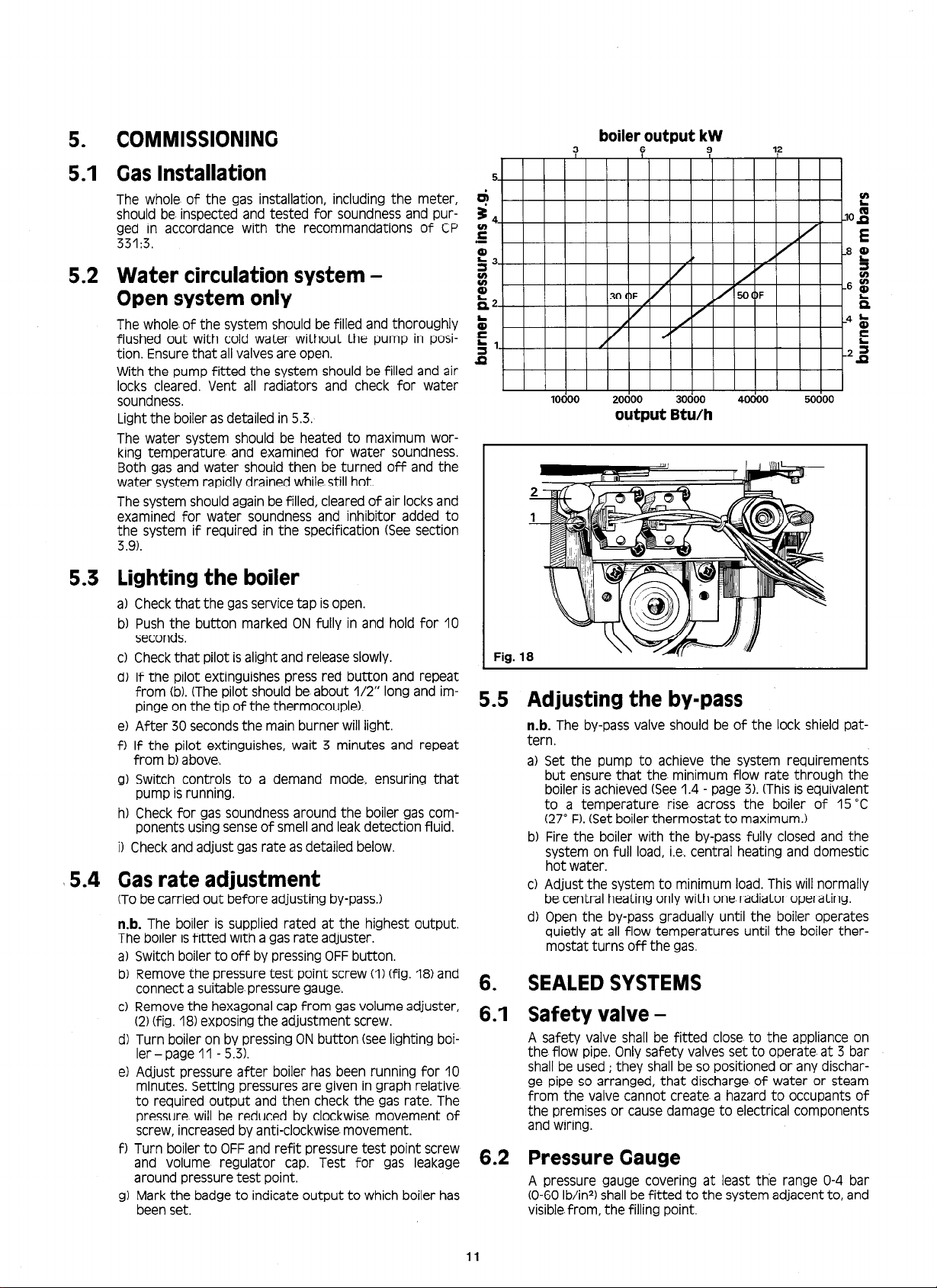
5.4 Gas rate adjustment
(To be carried out before adjusting by-pass.)
n-b.
The boiler is supplied rated at the highest output.
The boiler is fitted with a gas rate adjuster.
a) Switch boiler to off by pressing OFF button.
b) Remove the pressure test point screw (I) (fig. 18) and
connect a suitable. pressure gauge.
c) Remove the hexagonal cap from gas volume adjuster,
(2) (fig. 18) exposing the adjustment screw.
d) Turn boiler on by pressing ON button (see lighting boi-
ler - page 11 - 5.3).
e) Adjust pressure after boiler has been running for 10
minutes. Setting pressures are given in graph relative
to required output and then check the gas rate. The
pressure will be reduced by clockwise movement of
screw, increased by anti-clockwise- movement.
f) Turn boiler to OFF and refit pressure test point screw
and volume regulator cap Test for gas leakage
around pressure test point.
g) Mark the badge to indicate output to which boiler has
been set.
long
and im-
5
d
I II I I I I I I
10000
20000
30000
output Btu/h
Fig. 1
5.5 Adjusting the by-pass
n-b.
The by-pass valve should be of the lock shield pat-
tern.
a) Set the pump to achieve the system requirements
but ensure that the. minimum flow rate through the
boiler is achieved (See 1.4 - page 3). (This is equivalent
to a temperature. rise across the boiler of 15 ‘C
(27” F). (Set boiler thermostat to maximum.)
b) Fire the boiler with the by-pass fully closed and the
system on full load, i.e. central heating and domestic
hot water.
c) Adjust the system to minimum load. This will normally
be central heating only with one radiator operating
d) Open the by-pass gradually until the boiler operates
quietly at all flow temperatures until the boiler ther-
mostat turns off the gas.
6. SEALED SYSTEMS
6.1 Safety valve -
A safety valve shall be fitted close to the appliance on
the flow pipe. Only safety valves set to operate at 3 bar
shall be used ; they shall be so positioned or any discharge pipe so arranged, that discharge of water or steam
from the valve cannot create a hazard to occupants of
the premises or cause damage to electrical components
and wiring.
6.2 Pressure Gauge
A pressure gauge covering at least the range O-4 bar
(O-60 lb/in*) shall be fitted to the system adjacent to, and
visible.from, the filling point.
P
I I I I
40000 60000
11

6.3
Expansion vessel
(i) A diaphragm type- expansion vessel shall be fitted by
a connection to the inlet side of the circulating pump,
in a manner laid down in the vessel makers’ instructions (see fig. 18 for illustration of recommended system layouts). The expansion vessel shall be capable of
accepting water up to at least 62.5 % of its volume
without damage.
(ii) The nitrogen or air charge pressure of the expansion
vessel shall not be less than the hydro-static head
(height of the top point of the system above the expansion vessel).
(iii) The expansion vessel shall be sized in accordance with
the following Table.
;afety valve
Ming (bar)
lessel charge
lressure (bar)
nitial system
lressure (bar)
.otal water
:ontent
If system
litres
25
50
75
100
125
150
175
200
250
300
350
400
450
500
or systems
oiumesother
lanthosegiven
!~ve,multiply
lesystem
olumebythe
uztoracmss
- - - - -
2.1 3.5 8.5 13.7
4.2
6.3
8.3
10.4
12.5
14.6 24.5 45.3
16.7
20.8
25.0 42.0
29.1 49.0 90.6 192.8 38.1
33.3
37.5 63.0 18.5 247.9 49.0
41.6 M.0 25.9
-
l.083:
-
Expansion Vessel Volume (litres)
7.0 12.9
10.5
19.4 41.3 8.2
14.0
25.9 55.1 10.9
17.5 32.4
21.0
38.8 82.6 16.3
28.0
51.8 110.2 21.8
35.0 64.7 137.7 27.2
77.7
56.0 03.6
- -
0.140
-
2.7
27.5 5.4
68.9 13.6
96.4 19.1
185.3 32.7
220.4 43.6
275.5 54.5
- -
0.109
-
4.7 10.3
9.5 20.6
14.2 30.9
19.0 41.2
23.7 51.5
28.5 81.8
33.2 72.1
38.0 82.4
47.5 103.0
57.0 123.6
66.5 144.2
76.0 164.8
85.5 185.4
95.0 206.0
0.190 0.412 0.156
For the CHALLENGER boilers the above table should be
multiplied by 0.8
For the purpose of the above calculation, the volume of
the. system shall be determined as accurately as possible
using manufacturers’ data as appropriate. Alternatively
the volumes given below may be. used to give a conser-
vative estimate. ofthe system volume‘ :
Capacity boiler . . . . .
Small bore pipework . .
per 0.292 Kw (1000 Btu/h) of system output
Microbore pipework . . . 7 litres (I .5 gallons)
Steel panel radiators . .
per 0.292 Kw (1000 Btu/h) of system output
Hot water cylinder
If a system is extended, an expansion vessel of increased
volume may be required unless previous provision has
been made for the extension.
6.4 Hot Water storage Cylinder
The hot water cylinder shall be the indirect coil type
which is suitable.for the system pressure.
-
3.9
7.8
11.7
15.6
19.5
23.4
27.3
31.2
39.0
46.8
54.6
62.4
~~:~I 6.6 Mains Connection
70.2
78.0
-
6.7 Fihg Point
-
I
Provision shall be made for replacing water lost from the
system either :
0) From a make-up vessel or tank mounted in a position
higher than the top point of the system and connec-
ted through a non-return valve to the system on the
return side- of the. hot water cylinder or the return
side of all heat emitters, or -
(ii) Where access to make up vessel would be difficult, by
pressurisation of the system.
There shall be no connection to the mains supply or to
the water storage tank supplying domestic water, even
through a non-return valve, without the approval of the
local Water Authority.
For the filling system see BS 5376 Part 2 appendix A.
NB. A temporary hose connection is only permissible. if
acceptable. to the local Water Authority.
0.5 litres (0.11 gallons)
0.3 litres (0.07 gallons)
2.3 litres (0.5 gallons)
2 litres (0.44 gallons)
Pump on the return
Pump on the flow
8
Diagrams showing
System layout
I- Expansion vessel
2 - Pressure gauge
3 - Filling point
4 - Drain cock
5 - Air release point
6 - Safety valve
7 - Top-up bottle
8 - Temporary hose connection
or pressurisation make up.

5.8 Pipework
1.
6.8
Pipework should be of copper; small bore or microbore
with capillary or compression jointing to a high standard.
Leak sealant shall not be used in the system.
Where a vessel of the calculated size is not obtainable,
the next available larger size should be used.
6.9 Commissioning
Sealed System Only
The whole of the system should be filled and thoroughly
flushed out with cold water without the circulating pump
in position. Ensure that all valves are open. (The system
must be filled with water either from a sealed system filler pump with a break tank, or by any other method approved by the Local Water Undertaking).
With the circulating pump fitted the system should be
filled and airlocks cleared until the pressure gauge registers 1.5 bar (21.5 Ibf/in*).
Vent all radiators and check for water soundness.
Manually raise the water pressure to ensure that the safety valve lifts. This should occur within 2 0.3 bar (2 4.3
Ibf/in2) of the preset lift pressure, ie. 3 bar (43.5 Ibf/ir-?).
Release water from the system until the initial system
design pressure is attained, taking into account any difference in height between the pressure gauge and the
point at which the pressure vessel is connected.
Light the boiler as detailed in 5.3.
The water system should be heated to maximum wor-
king temperature and examined for water soundness.
Both gas and water should then be turned off and the
water system rapidly drained whilst still hot.
The system should again be filled, add inhibitor to the
system, if required in the specification (see 3.9), cleared
of air locks and adjusted to the initial design pressure.
Any set pointer on the pressure gauge should be set to
coincide with the indicating pointer. Examine for water
soundness.
Now adiust the oas rate and the svstem bv pass - See
5.4 and-5.5. -
t I I
I
rectifier
a2
iw
43
rc^
C?
/
24VDC
I
r I 1
I
transformer
211 ;
\I--
,?’
4
I
-1
thermistor
emperature
sensor
c--i
I A
A-- ,
I I
782 ‘.R43
36
4
‘“1
Fl4 D
comparitor
1 U
I
J2Z
R23
?=I
n
1 ” --- fuse
I
I
R24l
“5
b
-
+L
orange solenoid
I
S6
L
---7
i
trump
-_-- A
N2
Nl
240 V. 50 Hz
variable
I
I
i
1 Fig. 19

Ignition
Electrode
CHALLENGER TEST POINTS
Solenoid Valves
Orange and Blue
24 V m k 5 V m
! ! ! [
Printed Circuit Board
(Temperature & Sequence Control)
Fuse 2A
I ’
Transformer
1
Earth
I
Thermistor
sensor
v-
! ! 1 ilr in neutral side
L,.
Microswitch
mains voltage circuit
External Controls
Fig. 20
Thermoelectric
Valve
Thermocouple
Thermo-electric
valve
&
Electrode Solenoid valves
Blue
“/y////
240V 50Hz
Thermistor
temperature sensor
LB
n
Control box
Fig. 21
ro Q
External control
high-limit
thermostat
14

7. SERVICING
7.
For efficient and trouble free operation it is important that the CHALLENGER receives regular maintenance. The following
schedules are recommended
Before commencing any work turn of the gas at the gas inlet tap (section 4.4). Ensure that the electricity supply is disconnec-
ted.
Important
: Always test for gas soundness after completing and service or exchange of gas carrying components.
Remove front casing
a) Remove screws (A) from front of boiler - securing
front case to electrical control box.
b) Remove 2 screws (B) bottom rear of boiler.
c) Ease bottom forward and lift off front case from re-
taining hooks situated top rear of boiler.
d) Replace in reverse. order.
7.2
7.3
7.4
Remove combustion chamber front panel
a) Remove six screws securing front panel of combus-
tion chamber.
b) Remove panel by easing forward at bottom and di-
sengage from draught diverter by pulling downwards.
c) Replace in reverse. order.
Remove burner assembly
a) Remove two screws securing burner manifold to gas
section (A) and 2 outer screws U (50 OF only).
b) Remove gasket and retain in safe place.
c) Remove 2 screws (B) securing burner head to rear
chassis.
d) Replace in reverse order.
To remove pilot
a) Release thermocouple from bracket removing nut
and bolt (A) securing clamp. Move thermocouple to
the side.
b) Release. the electrode by loosening screw (B) on right
hand side of assembly and rotating retaining clip.
c) Remove pilot gauze and filter by removing screw se-
curing gauze. to assembly.
d) Remove pilot by unscrewing (nut size 8 mm AF) using
set or adjustable spanner.
e) The pilot injector can be cleaned and should be repla-
ced bright side uppermost.
f) Replace in reverse order.
15
Cleaning the parts
a) The burner can be cleaned by inverting and brushing with a soft brush.
b) The heat exchanger matrix can be cleaned by brushing. If deposits are too hard to remove by brushing, the matrix can be
removed -see section 8.7 page 17 and washed with hot water and detergent.
c) Any lint deposies in the burner ports should be removed using a suction cleaner and or washing.
d) The gas filter (B - 4.4) can be cleaned using water and detergent.
e) Replace all components in reverse order.
DO NOT USE SOLVENTS.
8.
8.1
8.2
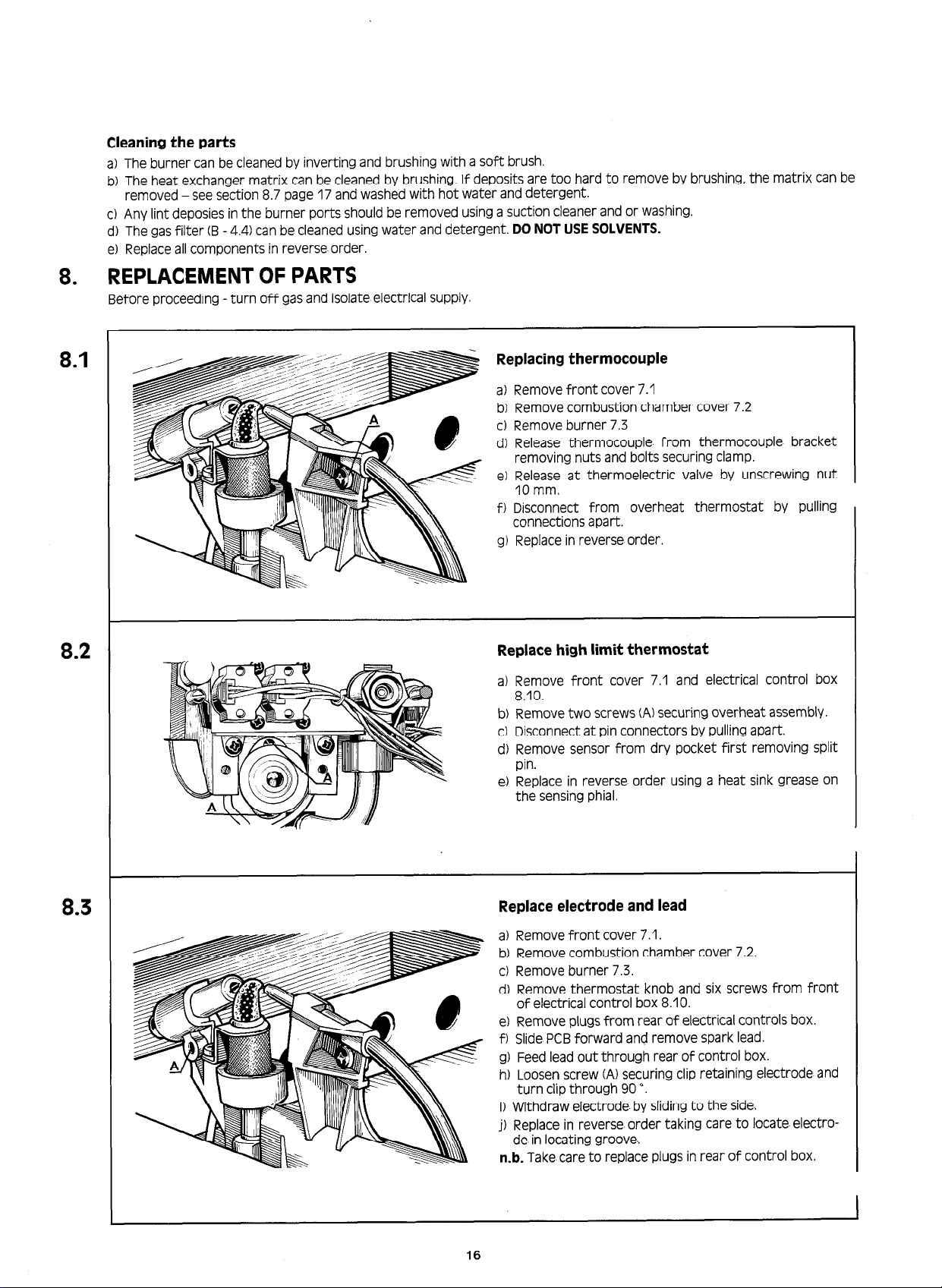
REPLACEMENT OF PARTS
Before proceeding - turn off gas and isolate electrical supply.
Replacing thermocouple
a) Remove front cover 7.1
b) Remove combustion chamber cover 7.2
c) Remove burner 7.3
d) Release thermocouple from thermocouple bracket
removing nuts and bolts securing clamp
e) Release at thermoelectric valve by unscrewing nut
IO mm.
f) Disconnect from overheat thermostat by pulling
connections apart.
g) Replace in reverse order.
Replace high limit thermostat
a) Remove front cover 7.1 and electrical control box
8.10.
b) Remove two screws (A) securing overheat assembly.
c) Disconnect at pin connectors by pulling apart.
d) Remove sensor from dry pocket first removing split
pin.
e) Replace in reverse order using a heat sink grease on
the sensing phial.
8.3
Replace electrode and lead
a) Remove front cover 7.1.
b) Remove combustion chamber cover 7.2.
c) Remove burner 7.3.
d) Remove thermostat knob and six screws from front
of electrical control box 8.10.
e) Remove plugs from rear of electrical controls box.
f) Slide PCB forward and remove spark lead.
g) Feed lead out through rear of control box.
h) Loosen screw (A) securing clip retaining electrode and
turn clip through 90 *.
i) Withdraw electrode by sliding to the side..
j) Replace in reverse order taking care to locate electro-
de in locating groove..
n-b.
Take care to replace plugs in rear of control box.
16
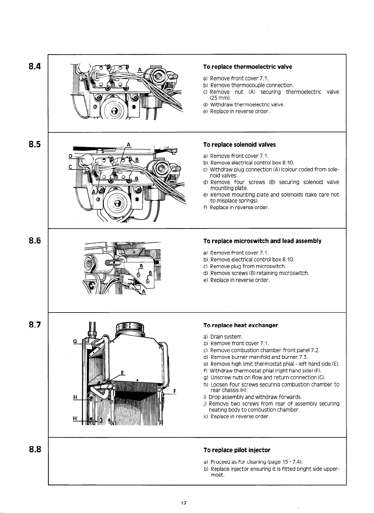
8.4
To replace thermoelectric valve
a) Remove front cover 7.1.
b) Remove thermocouple connection.
c) Remove nut (A) securing thermoelectric
(25 mm).
d) Withdraw thermoelectric valve.
e) Replace in reverse order.
valve
8.5
8.6
To replace solenoid valves
a) Remove front cover 7.1.
b) Remove electrical control box 8.10.
c) Withdraw plug connection (A) (colour coded from sole-
noid valves.
d) Remove four screws (B) securing solenoid valve
mounting plate.
e) Remove mounting plate and solenoids (take care not
to misplace springs).
f) Replace in reverse order.
To replace microswitch and lead assembly
a) Remove front cover 7.1.
b) Remove electrical control box 8.10.
c) Remove plug from microswitch.
d) Remove screws (B) retaining microswitch.
e) Replace in reverse order.
8.7
8.8
To replace heat exchanger
a) Drain system.
b) Remove front cover 7.1.
c) Remove combustion chamber front panel 7.2.
d) Remove burner manifold and burner 7.3.
e) Remove high limit thermostat phial - left hand side (E).
f) Withdraw thermostat phial (right hand side) (F).
g) Unscrew nuts on flow and return connection CC).
h) Loosen four screws securing combustion chamber to
rear chassis CH).
i) Drop assembly and withdraw forwards.
j) Remove two screws from rear of assembly securing
heating body to combustion chamber.
k) Replace in reverse order.
To replace pilot injector
a) Proceed as for cleaning (page 15 - 7.4).
b) Replace injector ensuring it is fitted bright side upper-
most
17
8.9
Rear Lining-
B
u
\1
\i
A+
7
Pi-7
\
‘“4
b
I=11
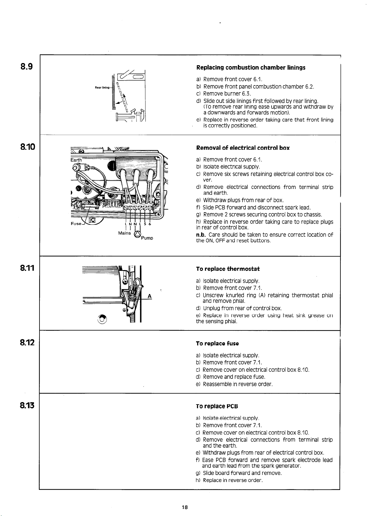
Replacing combustion chamber linings
a) Remove front cover 6.1.
b) Remove front panel combustion chamber 6.2.
c) Remove burner 6.3.
d) Slide out side.linings first followed by rear lining.
(To remove rear lining ease upwards and withdraw by
a downwards and forwards motion).
e) Replace in reverse order taking care that front lining
is correctly positioned.
8.10
8.11
Removal of electrical control box
a) Remove front cover 6.1.
b) Isolate electrical supply.
c) Remove six screws retaining electrical control box co-
ver.
d) Remove electrical connections from terminal strip
and earth.
e) Withdraw plugs from rear of box.
f) Slide PCB forward and disconnect spark lead.
g) Remove 2 screws securing control box to chassis.
h) Replace in reverse order taking care to replace plugs
in rear of control box.
n-b.
Care should be taken to ensure correct location of
the ON, OFF and reset buttons.
To replace thermostat
a) Isolate. electrical supply.
b) Remove front cover 7.1.
c) Unscrew knurled ring (A) retaining thermostat phial
and remove phial.
d) Unplug from rear of control box.
e) Replace in reverse order using heat sink grease on
the sensing phial.
8.12
8.13
To replace fuse
a) Isolate electrical supply.
b) Remove front cover 7.1.
c) Remove cover on electrical control box 8.10.
d) Remove and replace fuse.
e) Reassemble. in reverse order.
To replace PCB
a) Isolate. electrical supply.
b) Remove front cover 7.1.
c) Remove cover on electrical control box 8.10.
d) Remove electrical connections from terminal strip
and the earth.
e) Withdraw plugs from rear of electrical control box.
f) Ease PCB forward and remove spark electrode. lead
and earth lead from the spark generator.
g) Slide board forward and remove.
hl Replace in reverse order.
18

3.14
8.14
Testing the FFD circuit
Closed circuit :
- Slide back insulation at plug in connection and attach
millivolt meter using crocodile clip connectors.
- Output should not be less than 3 mv.
Open circuit :
- Disconnect round pin connectors.
- Attach millivolt meter using crocodile clips to the ther-
mocouple side - male connectors.
- Press and hold ignitor button.
- Output with pilot on should not be less than 14 mv.
n-b.
If closed circuit output is high and approaching the
open circuit voltage obtained, then suspect faulty
thermoelectric valve.
SHORT LIST
Key No
I=
3
4
7
IOa
IOb
20
21
26
30
31
32
34
35
36
37
43
109
118
119
163
186
26
IB
36
Description
Screw front case/electrical box securing ........................
Screwfrontcase/chassis ......................................
Temperatureselectorknob ...................................
Doorassembly30OF .........................................
Doorassembly50OF
Nut3/4”BSP ................................................
Olive (22 mm) ...............................................
Mountingbracket
Cableclampbracket ..........................................
Cableclamp .................................................
Screws cable clamp securing ...................................
Gasfilterwasher .............................................
Gasservicecock
Olive (15 mm) ...............................................
Nut1/2”BSP..
Thermistortemperaturesensor ...............................
High limit thermostat .........................................
Thermocouple ...............................................
Electrode and lead assembly ...................................
Printed circuit board .........................................
Fuse .......................................................
.........................................
............................................
.............................................
..............................................
21
GC Number Part Number
366 713 65622/01
366 311 39551103
366 553 64051
366 556
366 625 64148
366 558 47509
366 559 47508
366 257 21720/10
366 564 65519
366 565
366 714 45654/02
366 545 37309
366 566 65960
263 800 56489
366 642 56489
366 570 64153
366 636 65962
366 602 65961
366 593 63404
366 614 63176
264 446 44790
64147
27834
19
n
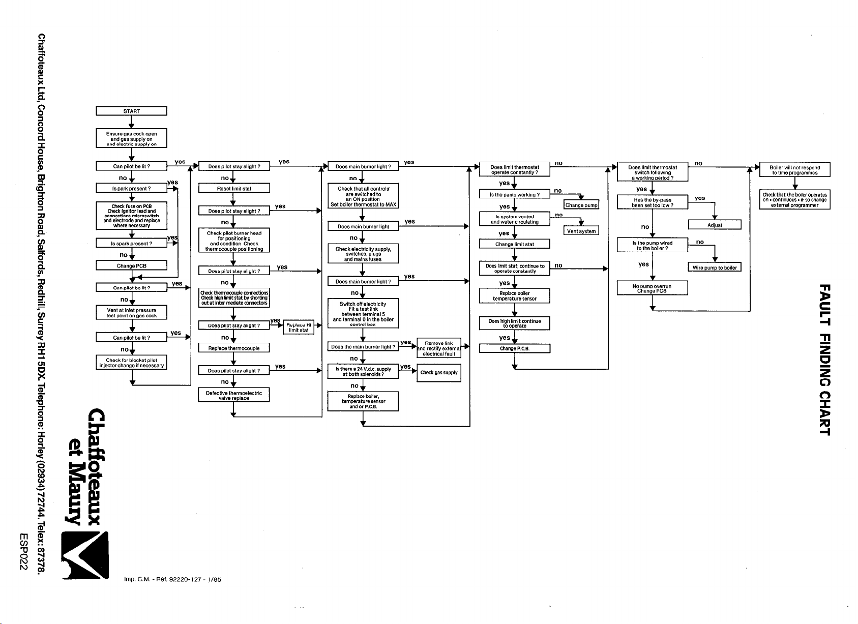
Pees main burner light ‘--
I
between terminal 5
and terminal 6 in the boiler
Change limit ~,a,
I
Is the pump wired
tothe boiler?
“0
I
Imp. C.M. - Ref. 92220-l 27 -
1185
 Loading...