

Page 1

HYBRID SYSTEM
SISTEMA HYBRID
GB
TALIA GREEN HYBRID
30
User instructions
Manuale d'uso per l'utente
IT
Page 2
User's manual
2
Dear Madam,
Dear Sir,
We would like to thank you for choosing our Hybrid system.
The technical quality of this product is guaranteed.
This booklet, including advice and recommendations, has been written
to provide information on your installation, its use and maintenance so
that you can make the most of all its features.
Please keep this booklet in a safe place for future reference.
Your nearest technical department will be happy to answer any queries.
Yours sincerely.
Follow the explanations on the warranty certi cate provided in the box.
CE marking
The CE mark guarantees that the Hybrid System meets the
requirements of directive:
- 90/396/CEE on gas appliances
- 2004/108/CEE on electromagnetic compatibility
- 92/42/CEE on energy e ciency
- 2006/95/CEE on safety of electrical equipment.
Safety standards
Key for the symbols :
Failure to respect the warnings leads to a risk of injury and may
even lead to death.
Failure to respect the hazard alerts may adversely a ect and
damage, seriously in some cases, property, plants or animals.
Do not carry out any operation which requires the appliance to be opened.
Contact with live components can cause electrocution.
Burn injuries from hot components or injuries caused by parts
that protrude or by cutting edges.
Do not carry out any operation which requires the appliance to be moved.
Contact with live components can cause electrocution.
Flooding caused by water escaping from disconnected pipes.
Explosions, res or poisoning caused by gas escaping from disconnected pipes.
Do not cause damage to the mains supply cable.
Electrocution caused by stripped live wires.
Never place any objects on the appliance.
Injuries can be caused by the item falling due to vibrations.
Damage to the appliance or items below it caused by items
that fall because of vibrations.
Do not climb on the appliance.
Injury can be caused by the appliance falling over.
Damage to the appliance or items below it due to the appliance
becoming detached from its supports and falling over.
Do not climb on chairs, step stools, ladders or unstable supports to clean the appliance.
Injury can be caused by falling from a raised height or by cuts
(folding ladder).
Do not carry out any cleaning operation on the appliance
unless the appliance has been switched o rst, with the
external switch moved to OFF.
Contact with live components can cause electrocution.
Do not use insecticides, solvents or harsh cleaning products for maintenance of the appliance.
Painted or plastic parts can be damaged.
Do not use the appliance for any use other than standard
household use.
The appliance may be damaged by operation overload.
Damage to incorrectly treated objects.
Do not allow children or inexperienced persons to use the
appliance.
Damage to the appliance may be caused by improper use.
If there is a smell of burning or ue gas coming from the
appliance, switch o the mains supply, close the gas tap,
open the windows and call a technician.
Injury caused by burns or inhalation of fumes, intoxication.
If there is a strong odour of gas, close the gas tap, open the
windows and call a technician.
Explosions, re or poisoning.
This appliance is not designed for use by persons (including
children) with reduced physical, sensory or mental capacities,
or who do not have su cient knowledge or experience, unless
they have bene ted from supervision and instruction concerning the use of the appliance by the person responsible for
their safety.
Children must be supervised to ensure they do not play with
the appliance.
Page 3
User's manual
3
TALIA GREEN HYBRID SYSTEM
Operating principle
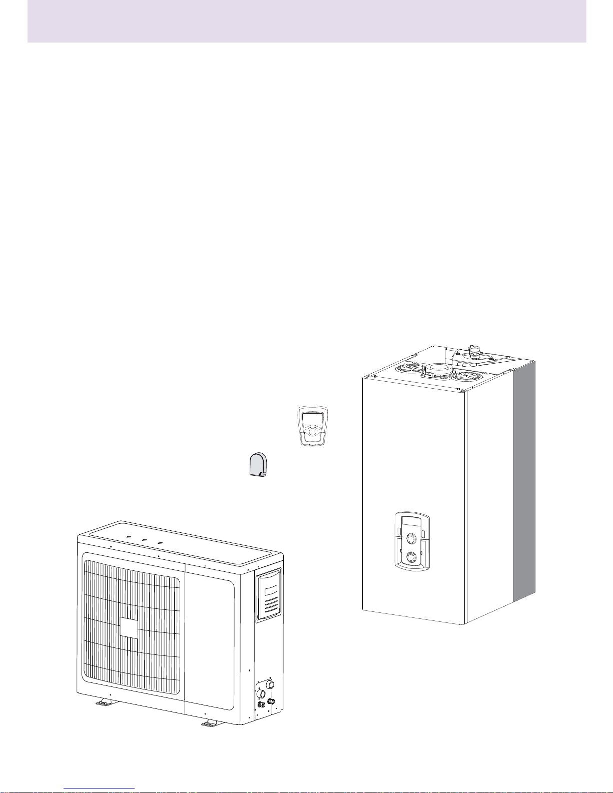
The TALIA GREEN HYBRID heating system comprises two heat
generators:
- a condensing boiler,
- an external single-unit air-to-water heat pump with INVERTER
technology.
Domestic hot water is produced exclusively by the boiler.
The combination of these two technologies means you can bene t
from the advantages of the two systems simultaneously, guaranteeing:
- exceptional comfort,
- a high level of e ciency,
- ease of installation,
- optimised operating costs,
- reliability,
- low investment cost.
The two heat generators are able to work together or separately to
meet your heating needs depending on the operating mode selected:
- Minimising primary energy consumption (default operation).
- Minimising operating costs.
To ensure this, the ENERGY MANAGER PCB constantly monitors the
temperatures in the heating circuit, the outdoor temperature, the
ambient temperature and the desired temperature (setpoint).
It uses this as the basis for calculating the e ciency of the boiler and
the COP of the heat pump.
Depending on the parameters initially set (electricity cost, gas
cost, operating mode), the ENERGY MANAGER decides which heat
generator is most suited to heating the building
.
System components
The HYBRID systems also allows the operating limits of the boiler and
of the heat pump to be de ned.
Minimum temperature for stopping the heat pump: this is temperature
below which the ENERGY MANAGER no longer authorises the
operation of the heat pump.
Maximum temperature for stopping the boiler: this is temperature above
which the ENERGY MANAGER no longer authorises the operation of
the boiler.
Within this temperature range, the ENERGY MANAGER selects the
most appropriate heat generator to use.
Boiler
Heat pump
Outdoor
sensor
Remote
control
Page 4
User's manual
4
This manual, together with the "Technical instructions
for installation and maintenance" should be kept with the
appliance. The manuals must be kept in a safe place and
must be passed onto any subsequent owners or users of
the boiler and/or in the event that the boiler is transferred
to another site.
The instructions and recommendations provided in this
manual should be read carefully.
This appliance is designed to supply hot water for domestic use.
It must be connected to a heating system and domestic hot water
supply network which are suitable for its performance levels and
power.
The TALIA GREEN HYBRID system is designed for installation with low
temperature radiators, fan coil units or a heated oor.
Any use other than that stipulated herein is prohibited. The
manufacturer shall in no way be held liable for any damages arising
from the improper, incorrect or unreasonable use of the appliance or
failure to follow the instructions contained in this manual.
The appliance must be installed by a professional technician who
is approved to t heating systems in accordance with the laws and
standards in force and who, once the work is completed, must submit
a declaration of conformity to the customer.
Installation, maintenance and all other operations must be carried
out by technicians with the requisite skills according to the applicable
regulations and the indications provided by the manufacturer.
If the power supply cable is damaged, it should be replaced by the manufacturer, the after-sales service or a person with a similar status, in order
to avoid potential danger.
If one of the two appliances is faulty or operating incorrectly, it is
possible to deactivate it and use the other device to meet all heating
requirements.
In a paragraph below, we will describe how to carry out this
modi cation using the control panel.
The production of domestic hot water is assured solely by the boiler.
In the event of a fault and/or incorrect operation of the boiler, switch
o the appliance and close the gas tap.
Regardless of which device is a ected, do not try to carry out the
repair yourself; call a quali ed professional.
For all repairs, call a quali ed technician and insist that genuine spare
parts are used.
Failure to comply with these instructions could compromise the safety
of the appliance and shall exempt the manufacturer from all liability.
If work or maintenance operations are carried out on structures close
to ducts or ue gas outlets, the boiler and their accessories, switch
o the appliance and, once the work has been completed, have the
condition of the ducts or outlets checked by a professional.
If the installation is not in use for prolonged periods:
- switch o the electricity by switching the external switches to the
"OFF" position,
- close the gas tap and the domestic cold water tap on the boiler,
- drain the heating and domestic hot water system (including the
boiler and the heat pump) if there is a risk of freezing.
If the system is being de nitively removed, contact a professional
boiler technician to carry out the necessary work.
To clean the exterior sections, switch o the system and turn the
external switches to "OFF".
Do not use or store ammable substances in the room where the
boiler is installed.
SRA
SRA function(automatic regulation system)
The SRA function serves to optimise the system's performance, while
maintaining an optimum radiator temperature and maximum user
comfort.
It ensures the building stays at the ideal temperature, whilst saving
energy.
The principle is that the water temperature at the boiler outlet
is automatically adjusted, depending on the interior ambient
temperature and the outside temperature.
To ensure correct operation of the Hybrid System, the SRA
function must be active.
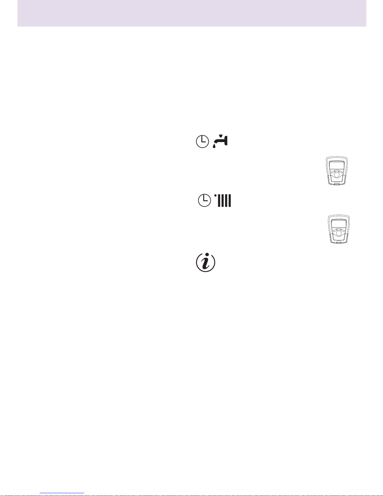
Domestic hot water timer programming
(Setting the REMOCON remote control)
The system allows the temperature of the plate heat
exchanger to be permanently maintained either via
C
OMFORT or Eco programming. The function is activated
using the remote control (REMOCON)
.
Heating timer programming
(Setting the REMOCON remote control)
The System allows the operation of the heating to be
programmed as required directly from the REMOCON
remote control panel, which displays the operating
periods throughout the day.
Info
Allows all information relating to operation of the Hybrid System and
its services to be accessed.
Page 5

User's manual
5
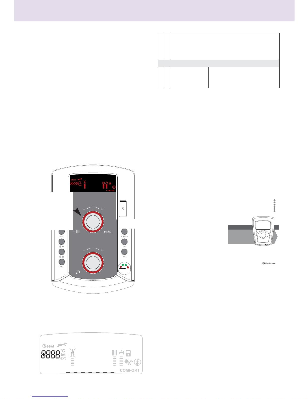
CONTROL PANEL
1. Display
2. ON/OFF key
3. Heating temperature setting button + programming
encoder
4. Summer/Winter operating MODE selection key
5
. Comfort key
6. Heating operating mode key for the TALIA GREEN HYBRID
7. SRA key (Activation of heat control)
8. Pressure gauge
9. Domestic hot water temperature selector button
10. INFO key
11. ESC key
12. MENU selection and programming con rmation key
13. RESET key
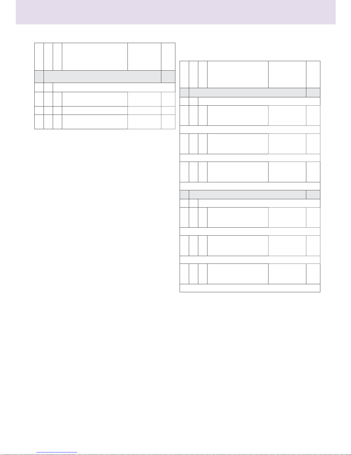
DISPLAY SYMBOLS
1
2
3
4
5
6
7
11
12
13
10
9
8
bar
1
3
2
ABCDEFGHIL123456
- menu setting
- error code indicator
- ambient temperature
(if connected to a regulator
peripheral)
Boiler locked, press the RESET key
Request for technical assistance
Flame uncrossed: boiler lit and
power indicator used.
Flame crossed: operation disabled
Heating operation with
temperature level set
Domestic hot water operation
with temperature level set
ABCDE...
Dropdown menu
Comfort domestic hot water
function activated
Info menu
SRA function activated (heating
control activated in factory)
Solar kit connected (INACTIVE)
Page 6
User's manual
6
IMPORTANT
Installation, rst commissioning and maintenance settings must only
be carried out by quali ed professionals, as per the instructions.
The manufacturer accepts no liability for any personal injuries, injuries
to animals or damage to goods as a result of any incorrect installation
of the appliance.
Recommendation during the operating period
If the Hybrid System boiler is installed inside the apartment, ensure
that the stipulations relating to the air intake and the ventilation of
the premises are followed (according to the laws in force).
Periodically check the water pressure on the display and check, when
the installation is cold, that the water pressure is between 0.6 and 1.5
bars. If the pressure is below the minimum value, the display shall
indicate that lling is necessary.
To re-establish the pressure, open the ller valve located under the
boiler and close it when the average value of 1 bar is reached.
If the pressure drops frequently, it is likely that the installation has a
water leak. In this case, contact a professional boiler technician.
Start up procedure
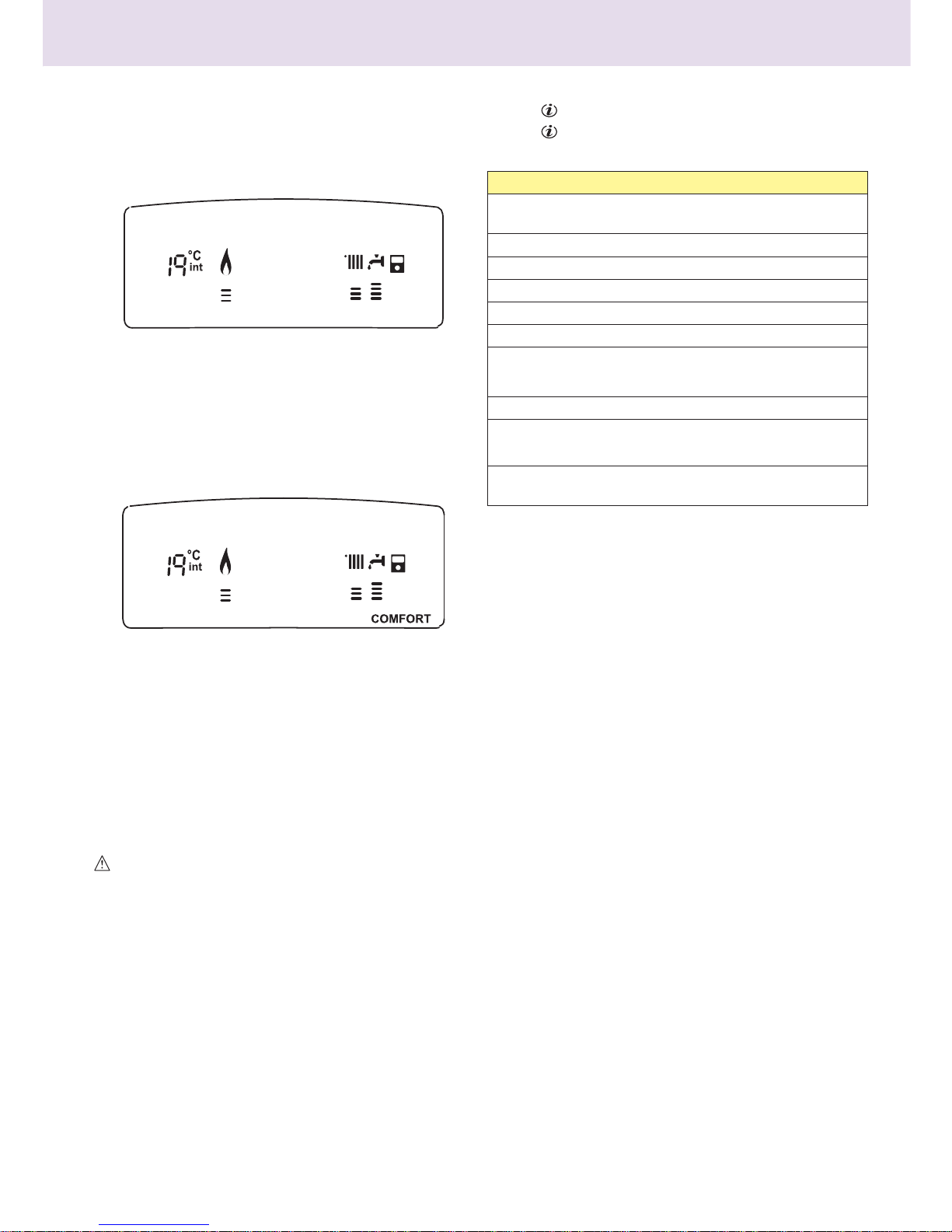
Press the ON/OFF key 2, the display comes on:
The operating status of the system is shown by the dropdown
menu:
Summer or Winter -Awaiting operation. The note on the display
indicates the operating mode selected:"Summer"
or "Winter"
Heating Heat pump+Boiler - Heating request
Heating Boiler only - Heating request
Heating Heat pump only - Heating request
Post Circ Heating- Post-circulation heating
DHW- Domestic hot water request
Anti-freeze protection - Anti-freeze protection operation
Note: The ignition of the boiler burner is signalled on the display
by symbol
The vertical level indicator shows the power used.
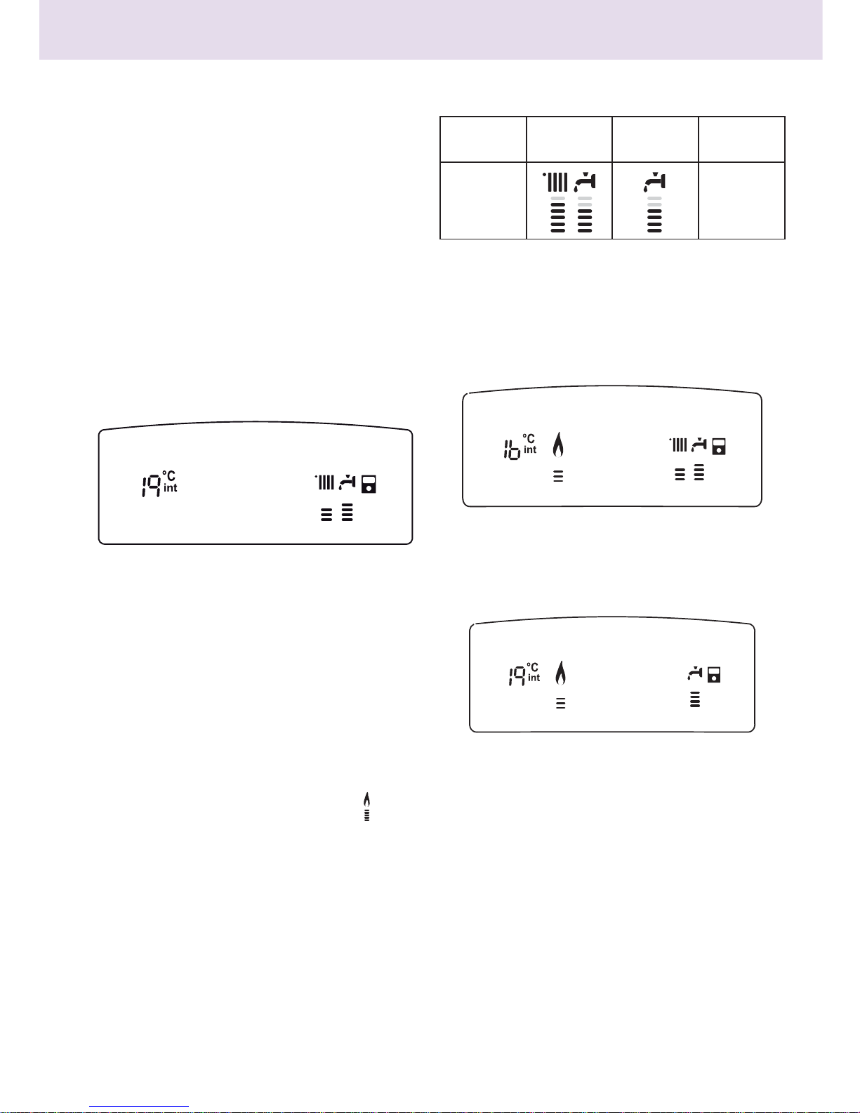
Selecting the operating mode
The operating mode is selected using MODE key 4 :
Heating regulation
The SRA function enables the system to independently adapt its
operating strategy to the outside conditions to control and maintain
the required ambient temperature.
When the SRA function is inactive, the temperature of the heating
water can be adjusted using the control button.
The selected setpoint value ashes for a few seconds then stays lit on
the vertical level indicator.
Stopping the heating
To switch the heating o , press the MODE key 4. The display symbol
disappears. Only the domestic hot water function remains on.
+LYHU
Mode
Winter heating
+ domestic hot
water
Summer
domestic hot
water only
Anti-freeze
protection
Display
Chauffage PAC + Chaudière
Sanitaire
Winter
Heat pump + Boiler heating
Domestic hot water
Page 7
User's manual
7
Domestic hot water regulation
This is on when the appliance is on. The temperature of the domestic
hot water can be adjusted between 40 and 65°C using setting button
9.
The selected setpoint value ashes for a few seconds then stays lit on
the vertical level indicator.
COMFORT function
The comfort level can be increased for the distribution of domestic
hot water using the COMFORT function. The temperature of the
secondary exchanger is maintained during periods of inactivity, in
order to reduce the waiting time for hot water when drawing o .
This function is activated by pressing the COMFORT key 5.
The plate heat exchanger's temperature is maintained 24 hours a day,
every day.
Boiler shutdown
Setting to standby
To shut down operation of the Hybrid System, press the ON/OFF key
2.
Hybrid System complete shutdown
To shut the system down completely, cut the main supply to the boiler
and the heat pump using the external electrical switches.
The display is switched o . Close the boiler's gas tap.
IMPORTANT
When the system is set to standby or shut down
completely, anti-freeze protection no longer operates
for the boiler, heat pump or heating installation.
INFO key
Press the key to access the data indicated in the table below.
Press the
key to move from one line to another.
Press the Esc key to exit the menu.
Sanitaire
Cycle comfort en cours
List of information displayed
Outdoor temperature (°C)
- only with external sensor connected (option)
Indoor temperature (°C)
Domestic hot water ow rate (l/min)
Heating setpoint temperature (°C)
Domestic hot water setpoint temperature (°C)
Months remaining before the next maintenance
Telephone and name for technical assistance
(displayed if data entered in parameters 890 - 891)
Domestic hot water comfort setpoint (°C)
SRA function
Activated or deactivated if the symbol is lit on the display
Storage temperature (°C)
only for boiler with storage tank
Domestic hot water
Comfort cycle in progress
Page 8
User's manual
8
Access to the display and setting menu
The Menu key 12 provides access to a series of menus which can
be used to adapt the system operation to the installation and your
requirements.
The following menus are available:
menu 0 = Language
menu 1 = Timer programming
(done using the remote control
- see Operating Instructions)
menu 3 = Solar and Tank (300 - 302)
menu 4 = Zone 1 parameters (400 - 401- 402)
menu 5 = Zone 2 parameters (500 - 501- 502)
menu 9 - Hybrid System (900 - 901)
Info menu = Info - accessible using the INFO key
The parameters associated with the accessible menus are described
in the following pages.
The various parameters are accessed and modi ed using the Menu/
OK, Mode and Encoder keys.
The number of the corresponding parameter menus is indicated at
point A on the display. A note in area B will usually appear.
Key to the display gures :
0, xed number
0
0, ashing number.
MENU 0 SETTING THE TIME, DATE AND LANGUAGE
Setting the display language
The language is set in menu 0 - submenu 0, as follows :
- press the MENU/OK key, and 000 ashes on the display
- press the MENU/OK key again, 000 ashes on the display
- press the M
ENU/OK key again to access the submenu
- turn the encoder, the available languages are shown on the
display. Select the desired language and press the M
ENU/OK key to
store the modi cation
- press the ESC key to exit the menu.
MENU 1 = TIMER PROGRAMMING
done using the remote control - see Operating Instructions
Weekly programming lets you adapt the boiler operation perfectly to
your requirements and lifestyle.
The 2 heating zones and the hot water can be programmed.
ABCDEFGHIL123456
bar
1
3
2
Menu/OK
key
Encoder
(settings button used to
increase or
decrease the
value of the
setting)
ABCDEFGHIL123456
Point A
Point B
menu
sub - menu
description
"Note on display"
0 LANGUAGE SELECTION
00Selecting Display
Language
"Language"
English
Italiano
Francais
...................
INSTRUCTIONS DE FONCTIONNEMENT
ISTRUZIONI OPERATIVE
OPERATING INSTRUCTIONS
INSTRUCCIONES OPERATIVAS
GEBRUIKSAANWIJZING
ΧΕΙΡΙΣΤΗΡΙΟ ΑΠΟΣΤΑΣΕΩΣ ΜΕ ΔΙΑΜΟΡΦΩΣΗ
COMMADE À DISTANCE
CONTROLLO REMOTO
REMOTE CONTROL
CONTROL REMOTO
AFSANDSBEDIENING
ΧΕΙΡΙΣΤΗΡΙΟ ΑΠΟΣΤΑΣΕΩΣ
EQ
HS
FA
DR
AD
FQ
Page 9
User's manual
9
MENU 3 - SOLAR AND TANK
(activated with solar kit connected)
Setting the domestic hot water comfort temperature
To set the comfort temperature, proceed as follows :
- press the Menu/OK key, 0000 ashes on the display
- turn the encoder to select menu 3300 - “Solar and Tank”
- press the Menu/OK key to acess the sub-menu,
3000
- “Basic setting”
ashes on the display
- press the Menu/OK key to acess the parameters,
30300
0 - “Tank
temperature setting” ashes on the display
- press the Menu/OK key to change the parameter
- turn the encoder to select a new value
- press the Menu/OK key to store the modi cation
- press the E
SC key to exit the menu.
Setting the reduced temperature
To set the reduced temperature, proceed as follows: :
- press the Menu/OK key, 0000 ashes on the display
- turn the encoder to select menu 3300 - “Solar and stor”
- press the Menu/OK key to acess the sub-menu, “Basic setting”
ashes on the display
- press the Menu/OK key to acess the parameters 30300 0 ashes on the
display
-
turn the encoder to select parameter
turn the encoder to select parameter 303022-
"Stor. reduced
"Stor. reduced
temperature setting"
temperature setting"
- press the Menu/OK key to change the parameter
- turn the encoder to select a new value
- press the Menu/OK key to store the modi cation
- press the ESC key to exit the menu.
MENUS 4 and 5 - Con guring the heating zones
MENU 4 - ZONE 1 PARAMETERS - Heating
MENU 5 - ZONE 2 PARAMETERS - Heating
Setting the comfort and reduced temperature for the
heating zone
If the boiler is connected to a modulating device, the desired comfort
and reduced ambient temperatures can be set based on the built-in
timer program.
In heating mode, the boiler's activation and operation are managed
so as to maintain the set temperatures.
menu
sub - menu
parameter
description
"Note on display" value
default
settings
3 SOLAR APPLIANCE AND TANK
3 0 BASIC SETTING
300Tank temperature setting from 40 to
65 °C
60
301INACTIVE
302Tank reduced temperature
setting
from 10 to
65 °C
35
menu
sub - menu
parameter
description
"Note on display" value
default
settings
4 ZONE 1 PARAMETER
4 0 ZONE 1 SETTING
400Zone 1 comfort
temperature setting
"Comfort ambient T"
from 16 to 30
(°C)
19
Activated only with the modulating device connected (option)
401Zone 1 reduced
temperature setting
"Reduced ambient T"
from 16 to 30
(°C)
16
Activated only with the modulating device connected (option)
402Heating xed temperatu-
re setting
"Heating xed temp"
from 35 to 82
(°C)
70
Activated only with temperature control and xed temperature
5 ZONE 2 PARAMETER
5 0 ZONE 2 SETTING
500Zone 1 comfort
temperature setting
"Comfort ambient T"
from 16 to 30
(°C )
19
Activated only with the modulating device connected (option)
501Zone 1 reduced
temperature setting
"Reduced ambient T"
from 16 to 30
(°C )
16
Activated only with the modulating device connected (option)
502Heating xed temperatu-
re setting
"Heating xed temp"
from 35 to 82
(°C)
70
Activated only with temperature control and xed temperature
Page 10

User's manual
10
Setting the comfort temperature
To adjust the ambient comfort temperature, proceed as follows:
- press the MENU/OK
key, and
key, and, 000
ashes on the display
ashes on the display
- turn the encoder to select menu
4
00 -
"Zone 1 parameters"
"Zone 1 parameters"
- press the MENU/OK
key to access the submenu
key to access the submenu 400 -
"Temp Setting"
"Temp Setting"
- press the MENU/OK
key to access parameter
key to access parameter 400 -
"Comfort
"Comfort
ambient T"
ambient T"
- press the MENU/OK key to change the parameter, turn the encoder
to select a new value
- press the MENU/OK key to store the modi cation
- press the ESC key to exit the menu.
Setting the reduced temperature
To adjust the ambient comfort temperature, proceed as follows:
- press the MENU/OK
key, and
key, and, 000
ashes on the display
ashes on the display
- turn the encoder to select menu 400 -
"Zone 1 parameters"
"Zone 1 parameters"
- press the MENU/OK
key to access the submenu
key to access the submenu 400 -
"Temp Setting"
"Temp Setting"
- press the MENU/OK key and turn the encoder to access parameter
401 - "Comfort ambient T"
- press the MENU/OK key to change the parameter, turn the encoder
to select a new value
- press the MENU/OK key to store the modi cation
- press the E
SC key to exit the menu.
To set the reduced temperature for zone 2 (if present), proceed in the
same way by selecting menu 5.
Setting the xed ow temperature for the heating zone
This parameter is used to modify the heating ow temperature if the
heating control is activated on the xed temperature.
The xed temperature can be xed for zone 1 and zone 2 (if present).
To set the installation's xed temperature, proceed as follows:
- press the M
ENU/OK
key, and
key, and, 000
ashes on the display
ashes on the display
- turn the encoder to select the menu 400 - "Parameter zone 1"
- press the MENU/OK
key to access the submenu
key to access the submenu 400 - "Temp Setting"
- press the key and turn the encoder to access parameter 402 -
"Heating xed temp"
"Heating xed temp"
- press the M
ENU/OK key to change the parameter, turn the encoder
to select a new value
- press the M
ENU/OK key to store the modi cation
- press the ESC key to exit the menu.
To set the xed temperature for zone 2 (if present), proceed in the
same way by selecting menu 5.
7DPELDQFHFRPIRUW
7DPELDQFHUpGXLWH
7HPSIL[H&+
Comfort ambient T
Reduced ambient T
Heating xed temp
Page 11

User's manual
11
MENU 9 - Hybrid System
ECO/COMFORT Heating operating mode
To select the Hybrid System's operating mode on the basis of energy
saving and comfort, proceed as follows:
- press the MENU/OK
key, and
key, and 000
ashes on the display
ashes on the display
- turn the encoder to select the menu 900 - "Hybrid System
Parameter"
- press the MENU/OK
key to access submenu
key to access submenu 900 - "User parameters"
- press the MENU/OK key and turn the encoder to access parameter
900 - "ECO/COMFORT Heating operating mode"
- press the MENU/OK key to change the parameter, turn the encoder
to select the operating mode
- press the MENU/OK key to store the modi cation
- press the ESC key to exit the menu.
This setting can be made by pressing and holding key 6, the Heating
operating mode key on the TALIA GREEN HYBRID for 5 seconds.
Boiler/Heat pump Manual-Forced
If one the two appliances is faulty or operating incorrectly, it is
possible to deactivate it and use the other device to meet all heating
requirements.
Proceed as follows:
- press the M
ENU/OK
key, and
key, and 000
ashes on the display
ashes on the display
- turn the encoder to select the menu 900 - "Hybrid System
Parameter"
- press the MENU/OK
key to access submenu
key to access submenu 900 - "User parameters"
- press the MENU/OK key and turn the encoder to access parameter
901 - "Boiler/Heat pump Manual-Forced function"
- press the MENU/OK key to change the parameter, turn the encoder
to select the appliance
- press the MENU/OK key to store the modi cation
- press the ESC key to exit the menu.
This setting can be made by pressing and holding key 4, the Mode
key, for 5 seconds and turning the encoder.
Following an intervention by a quali ed technician, the value of
parameter 901 must be reset to 0 - Auto.
Otherwise, the boiler or heat pump will be permanently excluded.
menu
sub-menu
parameter
description
"Note on display" value
default
settings
9 HYBRID SYSTEM PARAMETER
90
USER PARAMETERS
900
Operating mode
ECO/COMFORT Heating
0 = ECO PLUS
1 = ECO
2 = MODERATE
3 = COMFORT
4 = COMFORT
PLUS
2
The hybrid operating mode can be selected on the basis of
energy saving and comfort.
ECO PLUS - most economical operation
up to COMFORT PLUS, the most comfortable.
This setting can be made by pressing and holding key 6, the
Heating hybrid operating mode key, for 5 seconds
901
Boiler/Heat pump ManualForce d
0 = Auto
(System active)
1 = Boiler
only
2 = Heat pump
only
0
This parameter enables the hybrid to operate automatically
or in boiler only or heat pump only mode
This setting can be made by pressing and holding key 4, the
Mode key, for 5 seconds and turning the encoder.
Page 12

User's manual
12
SRA function
Activating the heating control using the SRA function serves to
optimise the system's performance according to the ambient
and outdoor conditions, while maintaining an optimum radiator
temperature. This ensures optimum comfort.
Contact our quali ed technician or approved Technical
Assistance Service for information on the appliances required for
it to operate and to have the boiler con gured according to your
installation.
Without this function, the temperature of the water in the heating
circuit is xed, and raised on the coldest days but excessive in midseason.
This type of operation may cause discomfort and waste energy.
The new SRA function calculates the best operating strategy for the
boiler and permanently adapts the temperature of the heating circuit
based on your installation, the ambient and outdoor conditions and
your request.
Please note
Activating the TALIA GREEN HYBRID function enables the
characteristics of the heat pump and to be exploited and the savings
resulting from its use to be increased.
Chauffage PAC+Chaudière
Heat pump + Boiler heating
Page 13

User's manual
13
TROUBLESHOOTING AND SAFETY ADVICE
Conditions for stoppage of the appliance
The boiler and heat pump are made safe via internal checks carried out
by the PCBs, which place the appliances on standby if a fault occurs.
A code ashes on the display to indicate the cause of the stoppage.
There are several types:
Safety shutdown
The
symbol appears with the ashing code.
This is a "VOLATILE" shutdown, which means that it is automatically
removed when the mains supply is cut.
In most cases, as soon as the cause of the stoppage disappears, the
appliance will restart and resume normal operation.
If not, move the external bipolar switch to the OFF position, close the
gas tap and contact a quali ed technician.
Note: if error 1 08 - Stop due to insu cient water pressure - occurs,
simply reset the boiler pressure.
Lockout
On the display, the symbol accompanied by the ashing code (e.g.
code 501).
This is a "NON VOLATILE" shutdown. This means it is not su cient to
simply cut the mains supply before attempting to switch the ignition
back on. It must be unlocked by pushing in key
fully. After
several attempts to unlock it and if it locks again, it may be necessary
for a quali ed technician to intervene.
Important
For safety reasons, the boiler will only allow a maximum of 5 unlocking
attempts in 15 minutes (pressing of the RESET key). After this, it is
completely locked. To unlock it, switch the mains supply o and on
using the external bipolar switch.
Table of di erent causes of locking
Anti-freeze protection function - SYSTEM
The boiler and the heat pump are equipped with a device which
controls the water temperature at the outlet of each exchanger.
When the temperature drops below the set values, the anti-freeze
protection function is activated.
The function requires the activation of the appliance's circulating pump
and if necessary ignition in heating mode.
The anti-freeze protection function can only operate correctly if:
- the appliances have an electric power supply,
- no safety shutdown or lock is in progress,
- the installation's pressure is correct- boiler,
- the system is being supplied with gas - boiler.
0DQTXH)ODPPH
Display Description
1 01
Overheat
5 01
No ame
1 03
Water circulation problem
1 04
1 05
1 06
1 07
1 08
Insu cient pressure
3 05
PCB fault
3 06
PCB fault
3 07
PCB fault
No ame
Page 14

Manuale d'usoUser's manual
14
GAS CHANGE (for the boiler)
Our boilers are designed to operate using methane gas and LPG.
If a conversion proves necessary, contact a quali ed technician or our
approved Technical Assistance Service.
SERVICING
It is obligatory and essential to have your appliance serviced to guarantee the safety, correct operation and service life of the boiler. It
must be carried out every year to comply with the law.
It is obligatory to carry out a combustion analysis every 2 years, in order to check the performance and pollutant emissions
of the boiler. All this work must be noted in the installation
booklet.
Page 15

Manuale d'uso
15
Norme di sicurezza
Legenda simboli:
Il mancato rispetto dell’avvertenza comporta rischio di lesioni, in
determinate circostanze anche mortali, per le persone
Il mancato rispetto dell’avvertenza comporta rischio di
danneggiamenti, in determinate circostanze anche gravi, per
oggetti, piante o animali
Non effettuare operazioni che implichino l’apertura dell’apparecchio.
Folgorazione per presenza di componenti sotto tensione.
Lesioni personali per ustioni per presenza di componenti surriscaldati
o per ferite per presenza di bordi e protuberanze taglienti.
Non effettuare operazioni che implichino la rimozione
dell’apparecchio dalla sua installazione.
Folgorazione per presenza di componenti sotto tensione.
Allagamenti per perdita acqua dalle tubazioni scollegate.
Esplosioni, incendi o intossicazioni per perdita gas dalle tubazioni
scollegate.
Non danneggiare il cavo di alimentazione elettrica.
Folgorazione per presenza di fi li scoperti sotto tensione.
Non lasciare oggetti sull’apparecchio.
Lesioni personali per la caduta dell’oggetto a seguito di vibrazioni.
Danneggiamento dell’apparecchio o degli oggetti sottostanti per la
caduta dell’oggetto a seguito di vibrazioni.
Non salire sull’apparecchio.
Lesioni personali per la caduta dell’apparecchio
Danneggiamento dell’apparecchio o degli oggetti sottostanti per la
caduta dell’apparecchio a seguito del distacco dal fi ssaggio.
Non salire su sedie, sgabelli, scale o supporti instabili per effettuare
la pulizia dell’apparecchio.
Lesioni personali per la caduta dall’alto o per cesoiamento (scale
doppie).
Non effettuare operazioni di pulizia dell’apparecchio senza aver
prima spento l’apparecchio, e portato l’interruttore esterno in
posizione OFF.
Folgorazione per presenza di componenti sotto tensione.
Non utilizzare insetticidi, solventi o detersivi aggressivi per la pulizia
dell’apparecchio.
Danneggiamento delle parti in materiale plastico o verniciate.
Non utilizzare l’apparecchio per scopi diversi da quello di un normale
uso domestico.
Danneggiamento dell’apparecchio per sovraccarico di
funzionamento.
Danneggiamento degli oggetti indebitamente trattati.
Non fare utilizzare l’apparecchio da bambini o persone inesperte.
Danneggiamento dell’apparecchio per uso improprio.
Nel caso si avverta odore di bruciato o si veda del fumo fuoriuscire
dall’apparecchio, togliere l’alimentazione elettrica, chiudere il
rubinetto principale del gas, aprire le fi nestre ed avvisare il tecnico.
Lesioni personali per ustioni, inalazione fumi, intossicazione.
Nel caso si avverta forte odore di gas, chiudere il rubinetto principale
del gas, aprire le fi nestre ed avvisare il tecnico.
Esplosioni, incendi o intossicazioni.
L’apparecchio non è destinato a essere utilizzato da persone (bambini
compresi) le cui capacità fi siche, sensoriali o mentali siano ridotte,
oppure con mancanza di esperienza o di conoscenza, a meno che esse
abbiano potuto benefi ciare, attraverso l’intermediazione di una persona
responsabile della loro sicurezza, di una sorveglianza o di istruzioni
riguardanti l’uso dell’apparecchio.
I bambini devono essere sorvegliati per sincerarsi che non giochino con
l’apparecchio
Egregio Signore,
desideriamo ringraziarLa per aver preferito nel suo acquisto la
caldaia di ns. produzione. Siamo certi di averLe fornito un prodotto
tecnicamente valido.
Questo libretto è stato preparato per informarLa, con avvertenze
e consigli, sulla sua installazione, il suo uso corretto e la sua
manutenzione per poterne apprezzare tutte le qualità.
Conservi con cura questo libretto per ogni ulteriore consultazione.
Il nostro servizio tecnico di zona rimane a Sua completa disposizione
per tutte le necessità.
GARANZIA
Per benefi ciare della garanzia è necessario contattare il Centro Assi-
stenza ARISTON di zona entro 3 mesi dalla
data di installazione della caldaia.
Verifi cato il buon funzionamento della caldaia, il Centro Assistenza
ARISTON Le fornirà tutte le informazioni per il suo corretto utilizzo
e procederà all’attivazione della Garanzia ARISTON consegnandoLe
copia dell’apposita cartolina.
Per avere il numero di telefono del Centro Assistenza più vicino
può chiamare il Numero Unico 199.111.222.
Marcatura CE
Il marchio CE garantisce la rispondenza dell’apparecchio alle seguenti
direttive:
- 2009/142/CEE - relativa agli apparecchi a gas
- 2004/108/EC - relativa alla compatibilità elettromagnetica
- 92/42/CEE - relativa al rendimento energetico
- 2006/95/EC - relativa alla sicurezza elettrica
Page 16

Manuale d'uso
16
Principio di funzionamento
Il sistema di riscaldamento TALIA GREEN HYBRID è composto da due
generatori:
- una caldaia a condensazione,
- una pompa di calore (PDC) aria/acqua a tecnologia inverter
monoblocco esterna.
L’acqua calda sanitaria è prodotta esclusivamente dalla caldaia.
La combinazione delle due tecnologie permette di sfruttare
simultaneamente i vantaggi dei due sistemi.
Ciò vi garantisce:
- un comfort eccellente,
- un rendimento elevato,
- facilità di installazione,
- ottimi costi di esercizio
- affi dabilità
- bassi costi di investimento.
I due generatori potranno funzionare insieme o separatamente
per soddisfare i bisogni di riscaldamento secondo la modalità di
funzionamento scelta:
- consumo minimo di energia primaria (default),
- minimi costi di esercizio.
A tal scopo la scheda elettronica ENERGY MANAGER controlla
continuamente le temperature nel circuito di riscaldamento: la
temperatura esterna, la temperatura ambiente e la temperatura di
mandata all’impianto.
Da questi valori deduce il rendimento della caldaia e il COP della pompa
di calore.
In relazione dei parametri impostati inizialmente, l’ENERGY MANAGER
decide qual è il generatore più adatto a riscaldare l’ambiente.
In caso di funzionamento con pannelli fotovoltaici rivolgersi ad un
tecnico qualifi cato per il settaggio del sistema.
Il sistema ibrido offre la possibilità di defi nire anche i limiti di
funzionamento della caldaia e della pompa di calore.
Minima temperatura di funzionamento della pompa di calore :è la
temperatura al di sotto della quale l’ENERGY MANAGER non autorizza
il funzionamento della pompa di calore.
Massima temperatura di funzionamento della caldaia: è la temperatura
al di sopra della quale l’ENERGY MANAGER non autorizza il
funzionamento della caldaia.
All’interno di questo intervallo di temperature, l’ENERGY MANAGER
decide quale generatore è più conveniente.
Caldaia
PDC
Sonda
esterna
Controllo
Remoto
Page 17

Manuale d'uso
17
Il presente libretto insieme al manuale “Istruzioni tecniche
per l’installazione e la manutenzione” costituisce parte
integrante ed essenziale del prodotto. Entrambi vanno
conservati con cura dall’utente e dovranno sempre
accompagnare la caldaia anche in caso di sua cessione ad
altro proprietario o utente e/o di trasferimento su altro
impianto.
Leggere attentamente le istruzioni e le avvertenze
contenute nel presente libretto e nel manuale di installazione
e manutenzione in quanto forniscono importanti
indicazioni riguardanti la sicurezza di installazione, d’uso e
di manutenzione.
Questo apparecchio serve a produrre acqua calda per uso domestico.
Deve essere allacciato ad un impianto di riscaldamento e ad una rete
di distribuzione di acqua calda sanitaria compatibilmente alle sue
prestazioni ed alla sua potenza.
Il sistema TALIA GREEN HYBRID è adatta ad installazioni con impianti di
riscaldamento a bassa temperatura, ventil-convettori ed installazioni
a pavimento.
È vietata l’utilizzazione per scopi diversi da quanto specifi cato. Il
costruttore non è considerato responsabile per eventuali danni
derivanti da usi impropri, erronei ed irragionevoli o da un mancato
rispetto delle istruzioni riportate sul presente libretto.
Il tecnico installatore deve essere abilitato all’installazione degli
apparecchi per il riscaldamento secondo la Legge n.46 del 05/03/1990
ed a fi ne lavoro deve rilasciare al committente la dichiarazione di
conformità
L’installazione, la manutenzione e qualsiasi altro intervento devono
essere effettuate nel rispetto delle norme vigenti e delle indicazioni
fornite dal costruttore.
In caso di guasto e/o cattivo funzionamento spegnere l’apparecchio,
chiudere il rubinetto del gas e non tentare di ripararlo ma rivolgersi a
personale qualifi cato.
Eventuali riparazioni, effettuate utilizzando esclusivamente ricambi
originali, devono essere eseguite solamente da tecnici qualifi cati. Il
mancato rispetto di quanto sopra può compromettere la sicurezza
dell’apparecchio e fa decadere ogni responsabilità del costruttore.
In caso di segnalazione di errori o cattivo funzionamento è possibile
disattivare uno dei componenti del Sistema laciando l'altro in funzione.
La procedura per la disattivazione di uno dei componenti del Sistema è
descritta nelle pagine seguenti a partire dal pannello di controllo.
La produzione di acqua calda ad uso sanitario è fornita unicamente
dalla caldaia.
In caso di segnalzione di errore o cattivo funzionamento del sistema
togliere l'alimentazione elettrica agli apparecchi e chiudere il rubinetto
del gas della caldaia.
Qualunque sia il dispositivo non funzionante non tentare di ripararlo
ma contattare un tecnico qualifi cato.
Per qualsiasi intervento sul Sistema Hybrid contattare sempre un
tecnico qualifi cato e richiedere l'utilizzo di pezzi di ricambio originali. Il
mancato rispetto di quanto sopra può compromettere la sicurezza del
sistema e fa decadere ogni responsabilità del costruttore.
Nel caso di lavori o manutenzioni di strutture poste nelle vicinanze dei
condotti o dei dispositivi di scarico dei fumi e loro accessori, spegnere
l’apparecchio e a lavori ultimati far verifi care l’effi cienza dei condotti o
dei dispositivi da personale tecnico qualifi cato.
In caso di inutilizzo prolungato della caldaia è necessario:
- togliere l’alimentazione elettrica portando l’interruttore esterno in
posizione “OFF”;
- chiudere i rubinetti del gas, dell’impianto termico e dell’impianto
sanitario;
- svuotare l’impianto termico (y compris la chaudière et la PAC) e
sanitario se c’è pericolo di gelo.
In caso di disattivazione defi nitiva del sistema hybrid o di uno dei suoi
componenti far eseguire le operazioni da personale tecnico qualifi cato.
Per la pulizia delle parti esterne spegnere la caldaia e portare
l’interruttore esterno in posizione “OFF”.
Non utilizzare o conservare sostanze facilmente infi ammabili nel locale
in cui è installata la caldaia.
Conforme al DM 174 del 06-04-2004 in attuazione della Direttiva
Europea 98/83 CE relativa alla qualità delle acque
SRA
Funzione SRA (Sistema di regolazione automatica)
La funzione SRA consente di ottimizzare le prestazioni del sistema,
mantenendo una temperatura ambiente ottimale con massimo comfort
per l'utente.
Garantisce quindi una temperatura ideale conseguendo nel contempo
un risparmio energetico.
La funzione SRA regola automaticamente la temperatura di uscita
dell'acqua della caldaia, a seconda della temperatura ambiente e la
temperatura esterna.
Per un corretto funzionamento del sistema ibrido, è importante
che la funzione SRA sia attiva.
Programmazione oraria acqua calda ad uso
sanitario
La funzione si attiva dal controllo remoto (REMOCON).
Il sistema permette di controllare e mantenere la temperatura
nello scambiatore secondario permanentemente o in base
alla programmazione oraria (Comfort o Eco)
Programmazione oraria riscaldamento
La funzione si attiva dal controllo remoto (REMOCON).
Il sistema permette di gestire il clima secondo le proprie
necessità, direttamente dal controllo remoto; così si
può pianfi care e visualizzare comodamente i periodi di
funzionamento durante la giornata.
Info
Permette di accedere a tutte le informazioni relative al funzionamento
e ai servizi del Sistema Hybrid.
Page 18

Manuale d'uso
18
PANNELLO COMANDI
1. Display
2. Tasto ON/OFF
3. Manopola regolazione temperatura riscaldamento
- utilizzata anche come “encoder” per la navigazione e
la programmazione all’interno dei menu di impostazione
come indicato nelle pagine seguenti.
4. Tasto MODE
(Selezione modalità di funzionamento caldaia (estate/
inverno)
5
. Tasto Comfort
6. Tasto selezione modalità di funzionamento del Sistema
TALIA GREEN HYBRID
7. Tasto SRA (Attivazione Termoregolazione)
8. Idrometro
9. Manopola regolazione temperatura sanitario
10. Tasto INFO
11. Tasto ESC
12. Tasto MENU/OK
13. Tasto RESET
SIMBOLI DISPLAY
1
2
3
4
5
6
7
11
12
13
10
9
8
bar
1
3
2
ABCDEFGHIL123456
Cifre per indicazione:
- Settaggio menu
- Segnalazione codici d’errore
- Temperatura ambiente
(se collegata ad una periferica BUS)
Richiesta pressione tasto Reset
(caldaia in blocco)
Richiesto intervento assistenza tecnica
Segnalazione presenza fi amma con
indicazione potenza utilizzata o blocco
funzionamento (fi amma barrata)
Funzionamento in riscaldamento con indicazione
livello di temperatura impostata
Funzionamento in sanitario con indicazione livello
di temperatura impostata
ABCDE...
Testo scorrevole
Funzione sanitario Comfort attivata
Menu Info
Funzione SRA attivata (Termoregolazione
attiva)
Clip-in solare collegato (NON ATTIVO)
Page 19

Manuale d'uso
19
ATTENZIONE
L’installazione, la prima accensione, le regolazioni di manutenzione
devono essere effettuate, secondo le istruzioni, esclusivamente da
personale qualifi cato.
Un’errata installazione può causare danni a persone, animali o cose, nei
confronti dei quali il costruttore non è considerato responsabile.
Predisposizione al funzionamento
Se la caldaia del Sistema Hybrid è installata all’interno dell’appartamento
verifi care che siano rispettate le disposizioni relative all’entrata dell’aria
ed alla ventilazione del locale (secondo le leggi vigenti).
Controllare periodicamente la pressione dell’acqua sull'idrometro
e verifi care, in condizione di impianto freddo, che questa abbia un
valore tra 0,6 e 1,5 bar. Se la pressione è al di sotto del valore minimo
provvedere al reintegro aprendo il rubinetto posto sotto la caldaia e
chiuderlo al raggiungimento del valore sopra indicato.
Se il calo di pressione è molto frequente è probabile che ci sia una
perdita d’acqua nell’impianto. In questo caso è necessario l’intervento
dell’idraulico.
Procedura di accensione
Premere il tasto ON/OFF (2) il display si illumina.
La modalità di funzionamento del sistema è indicata dal testo scorrevole:
Estate o Inverno - caldaia in stand-by, nessuna richiesta.
Il testo indica la modalità
di funzionamento selezionata.
Riscaldamento PdC+Caldaia - Richiesta riscaldamento
Riscaldamento solo Caldaia - Richiesta riscaldamento
Riscaldamento solo PdC- Richiesta riscaldamento
Post Circ Risc - Post-circolazione riscaldamento
Sanitario - Richiesta sanitario
Antigelo - Modalità anti-gelo
Nota:
L’accensione del bruciatore della caldaia viene segnalato sul display dal
simbolo i trattini sotto indicano la potenza utilizzata.
Selezione modalità di funzionamento
La scelta della modalità di funzionamento viene effettuata tramite il
tasto MODE (4):
Regolazione riscaldamento
La funzione SRA permette al sistema di adattare il suo regime di
funzionamento alle condizioni esterne per regolare e mantenere
la temperatura ambiente impostata.
Quando la funzione SRA non è attiva, è possibile regolare la temperatura
del riscaldamento agendo sulla manopola di regolazione 3
Il valore prescelto viene visualizzato sul display lampeggiante.
Interruzione riscaldamento
Per interrompere il riscaldamento premere il tasto MODE (4), dal
display scompare il simbolo . La caldaia rimarrà in funzionamento
estivo per la sola richiesta di acqua calda ad uso sanitario, indicando la
temperatura impostata.
Modalità di
funzionamento
inverno estate Protezione
antigelo
Display
Chauffage PAC + Chaudière
Sanitaire
+LYHU
inverno
Riscaldamento PdC+Caldaia
Sanitario
Page 20

Manuale d'uso
20
Regolazione temperatura sanitario
È possibile regolare la temperatura dell’acqua sanitaria agendo sulla
manopola 8 si ottiene una temperatura variabile da 36°C a 60°C.
Il valore prescelto viene visualizzato sul display lampeggiante ed indi-
cato dai trattini verticali
.
Funzione COMFORT
L’apparecchio consente di massimizzare il comfort nell’erogazione di
acqua sanitaria tramite la funzione “COMFORT”, che mantiene caldo lo
scambiatore secondario durante i periodi di inattività.
Lo scambiatore secondario viene tenuto a temperatura 24 ore su 24,
7 giorni su 7.
Tale funzione può essere attivata premendo il tasto 5.
Procedura di spegnimento della caldaia
Per spegnere la caldaia premere il tasto ON/OFF (2).
Per spegnere completamente la caldaia portare l’interruttore elettrico
esterno in posizione OFF, il display si spegne.
Chiudere il rubinetto del gas.
Procedura di spegnimento Sistema Hybrid
Per spegnere completamente il sistema, togliere l'alimentazione
elettrica della caldaia e della PDC portando l'interruttore esterno in
posizione di OFF. Il display si spegne.
Chiudere il rubinetto del gas della caldaia.
ATTENZIONE
L'arresto completo del sistema disattiva la protezione antigelo sia
della caldaia che della PDC.
Tasto INFO
Premendo il Tasto INFO (10) si accede al Menu.
Continuando a premere il tasto si scorrono i dati indicati nella tabella
sotto riportata.
Per uscire premere il tasto ESC (11).
Sanitaire
Cycle comfort en cours
Elenco informazioni visualizzate
Temperatura esterna (°C)
(solo con sonda esterna collegata - optional)
Temperatura interna (°C)
(solo con sensore ambiente modulante collegato - optional)
Portata acqua sanitaria (l/m)
Temperatura di mandata riscaldamento (°C)
Temperatura sanitario (°C)
Mesi mancanti alla prossima manutenzione
Telefono e Nome CAT
(viene visualizzato se impostato al parametro 890 -891)
Temperatura comfort sanitario (°C) - se attivata
Funzione SRA “Abilitata” o “Disabilitata”
si illumina il simbolo sul display
Sanitario
Ciclo Comfort in corso
Page 21

Manuale d'uso
21
Accesso ai Menu di Impostazione e Regolazione
Attraverso il tasto di programmazione MENU/OK
12 si ha accesso ad una
serie di menu che consentono di adattare il funzionamento della caldaia
all’impianto ed alle esigenze dell’utente.
I menu disponibili sono i seguenti:
menu 0 = Ora - Data - Lingua
menu 1 = Programmazione oraria
(attivo dal Controllo remoto - vedi libretto istruzioni)
menu 3 = Solare e Bollitore (Parametri 300-302)
menu 4 = Parametri zona 1 (Parametri 400-401-402)
menu 5 = Parametri zona 2 (Parametri 500-501-502)
menu 9 = Parametri Sistema HYBRID (Parametri 900-901)
menu Info = Info - accessibile con il Tasto INFO
I parametri relativi ai menu accessibili sono riportati nelle pagine
seguenti.
L’accesso e la modifi ca dei vari parametri viene effettuata attraverso il
tasto MENU/OK, il tasto MODE e l’encoder. Il numero e dei parametri
corrispondenti è indicato, sul display dalle cifre A. Ad ogni codice è
associato un testo descrittivo B.
Legenda indicazione delle cifre sul display:
0, rappresentazione di un numero fi sso
0
0, rappresentazione di un numero lampeggiante
MENU 0 -
IMPOSTAZIONE ORA, DATA, LINGUA
Impostazione lingua per display
L’impostazione della lingua viene effettuata dal menu 0 - sottomenu 0,
procedere come segue:
- premere il tasto MENU/OK, sul display lampeggia 0000
- premere nuovamente il tasto MENU/OK, sul display lampeggia 0000
- premere nuovamente il tasto MENU/OK per accedere al sotto-menu
- ruotando l’encoder sul display appariranno le lingue disponibili;
selezionata la lingua premere il tasto MENU/OK per memorizzare la
modifi ca
- premere il tasto ESC per uscire dal menu.
MENU 1- PROGRAMMAZIONE ORARIA
attiva dal Controllo Remoto - vedi manuale di istruzione
La caldaia permette di impostare la programmazione settimanale per
adeguare perfettamente il suo funzionamento alle vostre esigenze e al
vostro stile di vita.
La programmazioni può essere impostata sia su due zone di
riscaldamento che sul sanitario.
ABCDEFGHIL123456
bar
1
3
2
Ta st o
Menu/Ok
Encoder
(manopola di regolazione) Permette di aumentare o
diminuire i valori
preimpostati
ABCDEFGHIL123456
A
B
menu
sotto-menu
descrizione “Testo su Display”
0
IMPOSTAZIONE LINGUA
00
Selezione Lingua
Display
“Lingua”
English
Italiano
Francais
...................
INSTRUCTIONS DE FONCTIONNEMENT
ISTRUZIONI OPERATIVE
OPERATING INSTRUCTIONS
INSTRUCCIONES OPERATIVAS
GEBRUIKSAANWIJZING
ΧΕΙΡΙΣΤΗΡΙΟ ΑΠΟΣΤΑΣΕΩΣ ΜΕ ΔΙΑΜΟΡΦΩΣΗ
COMMADE À DISTANCE
CONTROLLO REMOTO
REMOTE CONTROL
CONTROL REMOTO
AFSANDSBEDIENING
ΧΕΙΡΙΣΤΗΡΙΟ ΑΠΟΣΤΑΣΕΩΣ
EQ
HS
FA
DR
AD
FQ
Page 22

Manuale d'uso
22
MENU 3 - SOLARE E BOLLITORE
(attivo con Kit solare collegato)
Impostazione temperatura sanitario/accumulo
- premere il tasto MENU/OK, lampeggia la cifra del menu 0000
- ruotare l’encoder fi no a selezionare il menu 3300 • “Solare e Bollitore”
- premere il tasto MENU/OK per accedere ai sotto-menu, lampeggia
3000 • “Impostaz Generali”
- premere il tasto MENU/OK per accedere ai parametri, lampeggia
300 0 • “Impostaz T Accumulo”
- ruotare l’encoder per selezionare il parametro 302 2
• “Impostaz T Ridotta Accumulo”
- premere il tasto MENU/OK per modifi care il parametro
- ruotare l’encoder per selezionare il nuovo valore
- premere il tasto MENU/OK per memorizzare la modifi ca
- premere il tasto ESC per uscire dal menu.
Impostazione temperatura ridotta sanitario/accumulo
- premere il tasto MENU/OK, lampeggia la cifra del menu 0000
- ruotare l’encoder fi no a selezionare il menu 3300 • “Solare e Bollitore”
- premere il tasto MENU/OK per accedere ai sotto-menu, lampeggia
3000 • “Impostaz Generali”
- premere il tasto MENU/OK per accedere ai parametri, lampeggia
30
0
0 • “Impostaz T Accumulo”
- ruotare l'encoder per selezionare il parametro
303022 • “Impostazione temperatura ridotta sanitario/accumulo”
- premere il tasto MENU/OK per modifi care il parametro
- ruotare l’encoder per selezionare il nuovo valore
- premere il tasto MENU/OK per memorizzare la modifi ca
- premere il tasto ESC per uscire dal menu.
MENU 4 - PARAMETRI ZONA 1 - riscaldamento
MENU 5 - PARAMETRI ZONA 2 - riscaldamento
Impostazione Temperatura giorno e notte
delle zone riscaldamento
In caso di collegamento della caldaia con dispositivo modulante è
possibile stabilire le temperature ambiente desiderate per il giorno e
per la notte, in base alla programmazione oraria inserita.
In modalità riscaldamento l’attivazione ed il funzionamento della
caldaia sono fi nalizzati al raggiungimento ed al mantenimento delle
temperature impostate.
menu
sotto-menu
parametri
descrizione
“Testo su Display” valore
settaggio di
fabbrica
3 SOLARE E BOLLITORE
3 0 IMPOSTAZIONI GENERALI
300Impostazione temperatura
sanitario/accumulo
da 40 a 65°C 60
301NON ACTIF
302Impostazione temperatura
ridotta sanitario/accumulo
da 10 a 65°C 35
menu
sotto-menu
parametri
descrizione
“Testo su Display” valore
settaggio di
fabbrica
4 PARAMETRI ZONA 1
4 0 IMPOSTAZIONE TEMPERATURE
400Impostazione Temperatura
Giorno
“Zona 1 TGiorno”
da 16 a 30
(°C )
19
Attivo solo con dispositivo modulante collegato (optional)
401Impostazione Temperatura
Notte Zona 1
“Zona 1 TNotte”
da 16 a 30
(°C )
16
Attivo solo con dispositivo modulante collegato (optional)
402Impostazione Temperatura
fi ssa riscaldamento
“Temperatura Fix Risc Zona 1”
da 35 a 82 (°C) 70
Attivo solo con termoregolazione a temperatura fi ssa
5 PARAMETRI ZONA 2
5 0 IMPOSTAZIONE TEMPERATURE
500Impostazione Temperatura
Giorno
“Zona 2 TGiorno”
da 16 a 30
(°C )
19
Attivo solo con dispositivo modulante collegato (optional)
501Impostazione Temperatura
Notte Zona 2
“Zona 2 TNotte”
da 16 a 30
(°C )
16
Attivo solo con dispositivo modulante collegato (optional)
502Impostazione Temperatura
fi ssa riscaldamento
“Temperatura Fix Risc Zona 2”
da 35 a 82 (°C) 70
Attivo solo con termoregolazione a temperatura fi ssa
Page 23

Manuale d'uso
23
Impostazione della Temperatura Giorno “Zona 1 TGiorno”
Per impostare la temperatura ambiente giorno, procedere come segue:
- premere il tasto MENU/OK, lampeggia la cifra del menu
0
000
- ruotare l’encoder fi no a selezionare il menu
4
400 • “Impost Temperature”
- premere il tasto MENU/OK per accedere ai sotto-menu, lampeggia
4000
0 • “Impostazione Zona 1”
- premere il tasto MENU/OK per accedere ai parametri, lampeggia
40400
0 • “Zona 1 TGiorno”
- premere il tasto MENU/OK per modifi care il parametro
- ruotare l’encoder per selezionare il nuovo valore
- premere il tasto MENU/OK per memorizzare la modifi ca
- premere il tasto ESC per uscire dal menu.
Per impostare la Temperatura Giorno della Zona 2 (se presente)
procedere come sopra indicato selezionando il menu 5.
Impostazione della temperatura Notte “Zona 1 TNotte”
Per impostare la temperatura ambiente notte, procedere come segue:
- premere il tasto MENU/OK, lampeggia la cifra del menu 0000
- ruotare l’encoder fi no a selezionare il menu
4400 • “Parametri Zona 1”
- premere il tasto MENU/OK per accedere ai sotto-menu, lampeggia
4000
0 • “Impost Temperature”
-
premere il tasto MENU/OK per accedere ai parametri, lampeggia 404000
- ruotare l’encoder fi no a selezionare il parametro
40401 1 • “Zona 1 TNotte”
- premere il tasto MENU/OK per modifi care il parametro
- ruotare l’encoder per selezionare il nuovo valore
- premere il tasto MENU/OK per memorizzare la modifi ca
- premere il tasto ESC per uscire dal menu.
Per impostare la Temperatura Notte della Zona 2 (se presente)
procedere come sopra indicato selezionando il menu 5.
Impostazione della Temperatura Fissa di Mandata
sulle zone di riscaldamento
Il parametro viene utilizzato per modifi care la temperatura di mandata
del riscaldamento se viene attivata la Termoregolazione a temperatura
fi ssa.
E’ possibile regolare la temperatura sulla Zona 1 e la Zona 2 (se
presente).
Per modifi care la temperatura fi ssata dall’installatore procedere come
segue:
- premere il tasto MENU/OK, lampeggia la cifra del menu
0
000
- ruotare l’encoder fi no a selezionare il menu
4400 • “Parametri Zona 1”
- premere il tasto MENU/OK per accedere ai sotto-menu, lampeggia
4000 0 • “Impost Temperature”
-
premere il tasto MENU/OK per accedere ai parametri, lampeggia 40400 0
- ruotare l’encoder fi no a selezionare il parametro
40402
2 • “Temperatura Fix Risc Zona 1”
- premere il tasto MENU/OK per accedere al parametro
- ruotare l’encoder per selezionare il nuovo valore del parametro
- premere il tasto MENU/OK per memorizzare la modifi ca
- premere il tasto ESC per uscire dal menu.
Per impostare la Temperatura Fissa Riscaldamento della Zona 2 (se
presente) procedere come sopra indicato selezionando il menu 5.
7DPELDQFHFRPIRUW
Zona 1 Tgiorno
7HPSIL[H&+
Temperatura Fix Risc
7DPELDQFHUpGXLWH
Zona 1 Tnotte
Page 24

Manuale d'uso
24
MENU 9 - SISTEMA HYBRID
Modalità di funzionamento ECO/CONFORT riscaldamento
Per selezionare la modalità di funzionamento del Sistema Hybrid
tra il massimo risparmio di energia o il massimo Comfort,
procedere come segue:
- premere il tasto MENU/OK, lampeggia la cifra del menu
0
000
- ruotare l’encoder fi no a selezionare il menu
900 • "Parametri Sistema Hybrid"
- premere il tasto MENU/OK per accedere ai sotto-menu,
lampeggia 900 • "Parametri utente"
- premere il tasto MENU/OK per accedere ai parametri,
lampeggia
900 • "Modalità di funzionamento ECO/COMFORT
riscaldamento"
- premere il tasto MENU/OK per modifi care il parametro
- ruotare l’encoder per selezionare la modalità di funzionamento
- premere il tasto MENU/OK per memorizzare la modifi ca
- premere il tasto ESC per uscire dal menu.
E' possibile accedere direttamente alla scelta della modalità di
funzionamento premendo per 5 secondi il pulsante (6).
Funzionamento in manuale
Caldaia/Pompa di Calore
In caso di errore o cattivo funzionamento di uno dei componenti del
Sistema è possibile disattivarlo lasciando l'altro in funzione.
Procedere come segue :
- premere il tasto MENU/OK, lampeggia la cifra del menu
0
000
- ruotare l’encoder fi no a selezionare il menu
900 • "Parametri Sistema Hybrid"
- premere il tasto MENU/OK per accedere ai sotto-menu,
lampeggia 900 • "Parametri utente"
- ruotare l'encoder per selezionare il parametro
901 • "Funzionamento in manuale Caldaia/Pompa di Calore"
- premere il tasto MENU/OK per modifi care il parametro
- ruotare l’encoder per selezionare la modalità di funzionamento
- premere il tasto MENU/OK per memorizzare la modifi ca
- premere il tasto ESC per uscire dal menu.
E' possibile accedere direttamente al parametro premendo per 5
secondi il tasto MODE (4). Ruotare l'encoder per selezionare la
modalità richiesta.
Attenzione!!
Dopo l'intervento di un tecnico qualifi cato è necessario modifi care
il valore del parametro 901. Selezionare 0 = AUTO per riattivare il
sistema.
menu
sotto-menu
parametri
descrizione
“Testo su Display” valore
settaggio di
fabbrica
9 PARAMETRI SISTEMA HYBRID
9 0 PARAMETRI UTENTE
900Modalità di funzionamento
ECO/CONFORT
riscaldamento
0 = ECO PLUS
1 = ECO
2 = MEDIO
3 = COMFORT
4 = COMFORT
PLUS
2
E' possibile selezionare la modailità di funzionamento del Sistema
Hybrid in funzione del risparmio di energia o del comfort:
Dalla modalità ECO PLUS (massimo risparmio energetico) alla
COMFORT PLUS (massimo comfort per l'utente).
E' possibile accedere direttamente alla scelta della modalità di
funzionamento premendo per 5 secondi il pulsante
(6).
901Funzionamento in manuale
Caldaia/Pompa di Calore
0 = Auto
(Sistema attivo)
1 = Solo Caldaia
2 = Solo Pompa
di Calore
0
Il parametro consente di selezionare il funzionamento in manuale dei
componenti del sistema.
E' possibile accedere direttamente al parametro premendo per 5
secondi il tasto MODE. Ruotare l'encoder per selezionare la modalità
richiesta.
Nota: Selezionando la modalità “Solo Pompa di Calore” la caldaia
rimane attiva solo per la produzione di acqua calda sanitaria.
Page 25

Manuale d'uso
25
FUNZIONE SRA
L'attivazione della termoregolazione tramite la funzione SRA permette
di ottimizzare il rendimento del Sistema Hybrid in funzione delle
condizioni ambiente (interne ed esterne), mantenendo la temperatura
richiesta ed il massimo Confort.
Contattare un nostro tecnico qualifi cato che provvederà ad
informarvi sui dispositivi collegabili alla caldaia ed a programmarla
in base all’impianto.
Senza questa funzione la temperatura dell'acqua nel circuito del
riscaldamento è impostata per essere adeguata alle giornate più fredde
ma eccessiva nei periodi di mezza-stagione.
Questo tipo di funzionamento riduce il comfort e comporta sprechi di
energia.
La nuova funzione SRA calcola il migliore regime di funzionamento
per il sistema e adatta la temperatura del circuito di riscaldamento in
base alla tipologia di impianto e delle condizioni ambientali esterne per
raggiungere e mantenere la temperatura impostata.
Importante!!
L'attivazione della funzione SRA per il Sistema TALIA GREEN HYBRID
consente di sfruttare le caratteristiche della pompa di calore e per
aumentare il risparmio derivante dal suo utilizzo.
Riscaldamento PdC+Caldaia
SRA
Page 26

Manuale d'uso
26
Condizioni di arresto del Sistema Hybrid
La caldaia e la Pompa di Calore sono protette da malfunzionamento
tramite controlli interni da parte della scheda elettronica, che opera se
necessario un blocco di sicurezza. In caso di blocco viene visualizzato
sul display del pannello comandi un codice e la relativa descrizione che
si riferisce al tipo di arresto ed alla causa che lo ha generato.
Arresto di sicurezza
Questo tipo di errore è di tipo “volatile”, ciò signifi ca che viene
automaticamente rimosso al cessare della causa che lo aveva provocato.
Sul display lampeggia Err ed il codice dell’errore (es. Err/108) ed appare
il simbolo
Non appena la causa dell’arresto scompare, l'apparecchio riparte e
riprende il suo normale funzionamento.
Se l'apparecchio segnalerà ancora l’arresto di sicurezza, spegnerlo e
portare l’interruttore elettrico esterno in posizione OFF, chiudere il
rubinetto del gas e contattare un tecnico qualifi cato.
Nota : In caso di errore 108 - Arresto di insuffi ciente pressione
dell’acqua, provvedere al reintegro la pressione della caldaia.
Blocco di funzionamento
Questo tipo di errore è di tipo “non volatile”, ciò signifi ca che non viene
automaticamente rimosso.
Sul display lampeggia Err ed il codice dell’errore (es.
Err
Err/
501
501). Compare
inoltre la scritta RESET ed il simbolo .
In questo caso la caldaia non riparte automaticamente e potrà essere
sbloccata solo tramite la pressione del tasto RESET.
Dopo alcuni tentativi di sblocco, se il problema si ripete è necessario far
intervenire un tecnico qualifi cato.
Importante
Per motivi di sicurezza, la caldaia consentirà comunque un
numero massimo di 5 riarmi in 15 minuti (pressioni del tasto
RESET).
Tabella Errori per Blocco di Funzionamento
Funzione Antigelo - Sistema HYBRID
La caldaia e la PdC sono protetti da un dispositivo che controlla la
temperatura dell'acqua in uscita da ogni scambiatore di calore.
Se la temperatura scende sotto dei valori predeterminati la funzione
antigelo si attiva.
La funzione antigelo attiva i circolatori degli apparecchi e se necessario
attiva la modalità riscaldamento.
La funzione antigelo non si attiva correttamente se:
- gli apparecchi sono alimentati elettricamente,
- nessun arresto di sicurezza o di blocco è in corso,
- la pressione dell'installazione è corretta - caldaia
- il gas viene erogato - caldaia.
0DQTXH)ODPPH
Mancanza fi amma
Display Descrizione
1 01
Sovratemperatura
5 01
Mancanza fi amma
1 03
Circolazione Insuffi ciente
1 04
1 05
1 06
1 07
1 08
Pressione Insuffi ciente
3 05
Errore scheda
3 06
Errore scheda
3 07
Errore scheda
Page 27

Manuale d'uso
27
Cambio gas (solo per la caldaia)
Le nostre caldaie sono progettate sia per il funzionamento con il gas metano
che con i gas GPL.
In caso si renda necessaria la trasformazione, rivolgersi ad un tecnico
qualifi cato o ad un nostro Servizio Assistenza Tecnica autorizzato.
Manutenzione
La manutenzione periodica è essenziale per la sicurezza, il buon
funzionamento e la durata del Sistema Hybrid e va effettuata in base a
quanto previsto dalle norme vigenti
Page 28

420000463401 - 10/2012
8dhidYZaaVX]^VbViVYViZaZ[dcdÒhhd/%!&)(:jgdVab^cjid^c
[VhX^VdgVg^V^ciZgVZ%!%*+:jgd^c[VhX^VdgVg^Vg^YdiiV>kV^cXajhV
Ariston Thermo SpA
Viale A. Merloni, 45
60044 Fabriano (AN)
Tel. 0732.6011
Fax 0732.602331
http://www.aristonthermo.it
www.cha oteaux.it
 Loading...