

Page 1
EXPERT CONTROL
Istruzioni di installazione ed uso
Assembly and operation instructions
3318596
OK
INTERFACCIA DI SISTEMA
SYSTEM INTERFACE
INTERFACE DE SYSTÈME
SYSTEEMINTERFACE
IT
GB
FR
BE
Page 2

2
IT
indice
generalità ……………………………………………………………………………………… 3
norme di sicurezza ………………………………………………………………………… 4
caratteristiche tecniche ………………………………………………………………… 5
descrizione prodotto ……………………………………………………………………… 6
struttura menu ……………………………………………………………………………… 8
impostazione display …………………………………………………………………… 10
modalità funzionamento caldaia ………………………………………………… 12
regolazione temperatura ambiente……………………………………………… 13
impostazione acqua calda riscaldamento …………………………………… 14
programmazione oraria riscaldamento ……………………………………… 15
funzionamento modalità manuale riscaldamento ……………………… 18
impostazione acqua calda sanitaria …………………………………………… 19
programmazione oraria acqua calda sanitaria …………………………… 20
funzioni speciali …………………………………………………………………………… 21
solare & bollitore (se disponibile) ………………………………………………… 22
area tecnica
installazione ………………………………………………………………………………… 23
struttura menu area tecnicna ……………………………………………………… 25
impostazione zona ……………………………………………………………………… 26
menu confi gurazione guidata ……………………………………………………… 25
termoregolazione ………………………………………………………………………… 29
tabella menu ………………………………………………………………………………… 31
tabela codici errori ……………………………………………………………………… 57
Page 3

3
IT
L’interfaccia di sistema EXPERT CONTROL vi permette di dialogare con la caldaia dall’ambiente preferito della vostra
casa. Potrete così installare la caldaia
nel luogo più indicato e comandarla a
distanza.
L’interfaccia di sistema EXPERT CONTROL vi consente una semplice ed effi cace gestione della termoregolazione
degli ambienti ed il controllo dell’acqua
calda sanitaria.
Vi fornisce inoltre il primo aiuto, in caso
di malfunzionamento della caldaia,
segnalando il tipo di anomalia e suggerendo gli interventi per eliminarla o
consigliando l’intervento del Centro Assistenza.
Il presente libretto costituisce parte integrante ed essenziale del prodotto.
Leggere attentamente le istruzioni e le
avvertenze contenute nel presente libretto in quanto forniscono importanti
indicazioni riguardanti l’uso e la manutenzione.
L’installazione, la manutenzione e qualsiasi altro intervento devono essere effettuate da personale in possesso dei
requisiti previsti e nel rispetto delle norme vigenti e delle indicazioni fornite dal
costruttore.
In caso di guasto e/o cattivo funzionamento spegnere l’apparecchio e non
tentare di ripararlo ma rivolgersi a personale qualifi cato.
Eventuali riparazioni, effettuate utilizzando esclusivamente ricambi originali,
devono essere eseguite solamente da
tecnici qualifi cati. Il mancato rispetto di
quanto sopra può compromettere la sicurezza dell’apparecchio e fa decadere
ogni responsabilità del costruttore.
Prima di effettuare la pulizia delle parti
esterne spegnere l’apparecchio.
generalità
Page 4
4
IT
norme di sicurezza
LEGENDA SIMBOLI:
Il mancato rispetto dell’avvertenza
comporta rischio di lesioni, in determinate circostanze anche mortali, per
le persone
Il mancato rispetto dell’avvertenza
comporta rischio di danneggiamenti,
in determinate circostanze anche gravi, per oggetti, piante o animali
Non effettuare operazioni che implichino la rimozione dell’apparecchio
dalla sua installazione.
Danneggiamento dell’apparecchio.
Non salire su sedie, sgabelli, scale o
supporti instabili per effettuare la pulizia dell’apparecchio.
Lesioni personali per la caduta dall’alto o per cesoiamento (scale doppie).
Non utilizzare insetticidi, solventi
o detersivi aggressivi per la pulizia
dell’apparecchio.
Danneggiamento delle parti in materiale plastico o verniciate.
Non utilizzare l’apparecchio per scopi
diversi da quello di un normale uso
domestico.
Danneggiamento dell’apparecchio per
sovraccarico di funzionamento.
Danneggiamento degli oggetti indebitamente trattati.
Non fare utilizzare l’apparecchio da
bambini o persone inesperte.
Danneggiamento dell’apparecchio per
uso improprio.
ATTENZIONE!
L’apparecchio non è destinato a essere
utilizzato da persone (bambini compresi)
le cui capacità fi siche, sensoriali o mentali siano ridotte, oppure con mancanza
di esperienza o di conoscenza, a meno
che esse abbiano potuto benefi ciare, attraverso l’intermediazione di una persona
responsabile della loro sicurezza, di una
sorveglianza o di istruzioni riguardanti l’uso dell’apparecchio.
I bambini devono essere sorvegliati per
sincerarsi che non giochino con l’apparecchio.
QUESTO PRODOTTO
È CONFORME ALLA
DIRETTIVA EU 2002/96/EC
Il simbolo del cestino barrato riportato
sull’apparecchio indica che il prodotto, alla
fi ne della propria vita utile, dovendo essere
trattato separatamente dai rifi uti domestici, deve essere conferito in un centro di
raccolta differenziata per apparecchiature
elettriche ed elettroniche oppure riconsegnato al rivenditore al momento dell’acquisto di una nuova apparecchiatura equivalente.
L’utente è responsabile del conferimento
dell’apparecchio a fi ne vita alle appropriate
strutture di raccolta.
L’adeguata raccolta differenziata per l’avvio successivo dell’apparecchio dismesso
al riciclaggio, al trattamento e allo smaltimento ambientalmente compatibile contribuisce ad evitare possibili effetti negativi
sull’ambiente e sulla salute e favorisce il
riciclo dei materiali di cui è composto il
prodotto.
Per informazioni più dettagliate inerenti i
sistemi di raccolta disponibili, rivolgersi al
servizio locale di smaltimento rifi uti, o al
negozio in cui è stato effettuato l’acquisto.
Page 5
5
IT
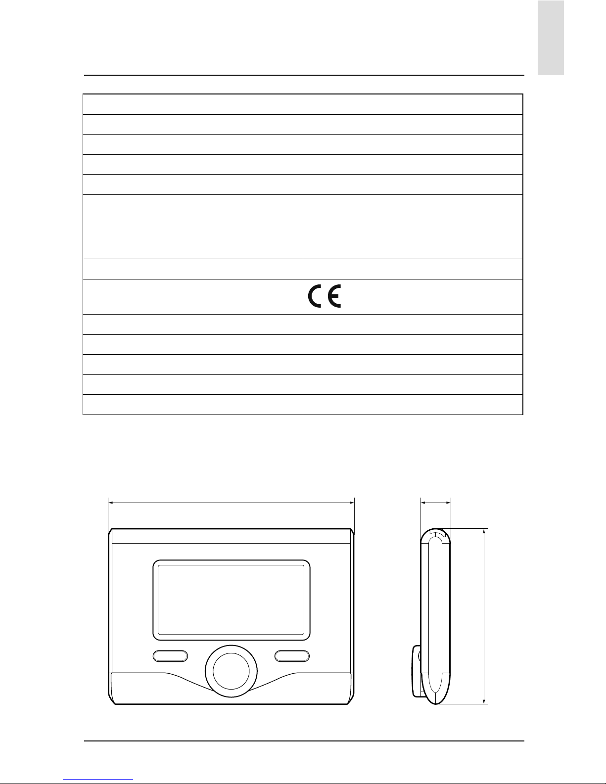
caratteristiche tecniche
Dati tecnici
Alimentazione elettrica BUS
Assorbimento elettrico max. < 0,5W
Temperatura di funzionamento -10 ÷ 60°C
Temperatura di stoccaggio -20 ÷ 70°C
Lunghezza e sezione cavo bus
NOTA:
NEL COLLEGAMENTO TRA SENSORE AMBIENTE E CALDAIA, PER EVITARE PROBLEMI DI INTERFERENZE, UTILIZZARE UN CAVO SCHERMATO O UN DOPPINO TELEFONICO.
max. 50 m - min. 0.5 mm²
Memoria tampone 2 h
Comformità
LVD 2006/95/EC - EMC 2004/108/EC
Interferenze elettromagnetiche EN 60730-1
Emissioni elettromagnetiche EN 60730-1
comformità standard EN 60730-1
Sensore temperatura NTC 5 k 1%
Grado di risoluzione 0,1°C
134 mm 16 mm
96 mm
Page 6
6
IT
descrizione del prodotto
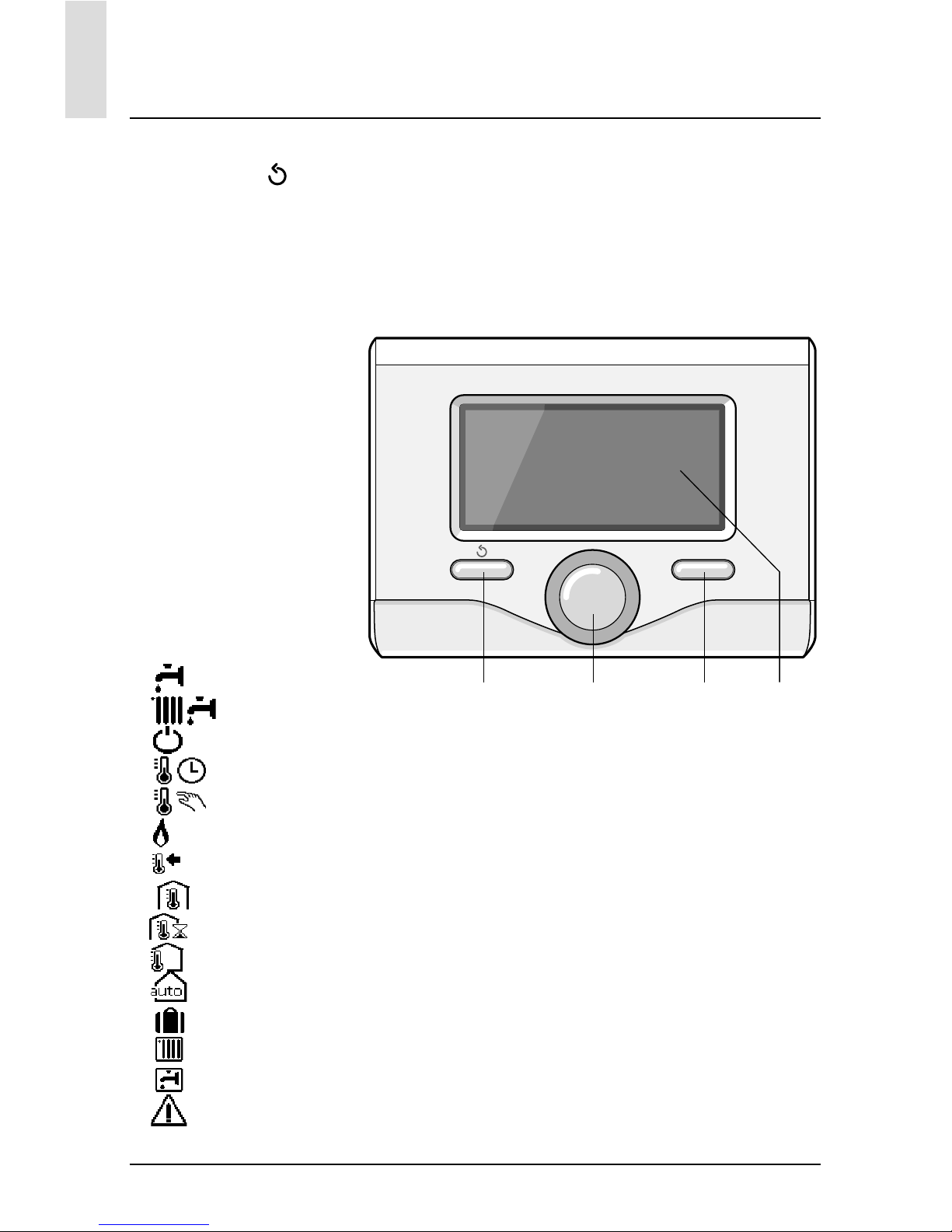
Tasti e Display:
1. tasto indietro
(visualizzazione precedente)
2. manopola
3. tasto
OK
(conferma l’operazione
o accede al menu principale)
4. DISPLAY
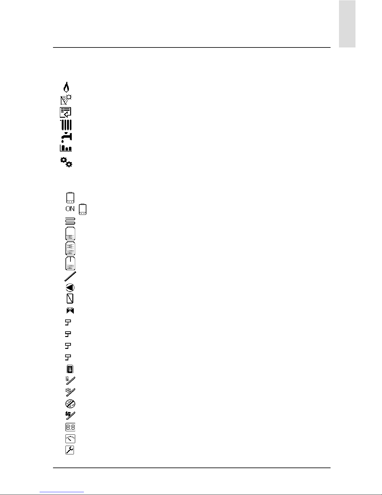
Simboli display:
- (
) Estate
- (
) Inverno
- (
) OFF caldaia spenta
- (
) Programmazione oraria
- (
) Funzionamento manuale
- (
) Indicazione presenza fi amma
- (
) Temperatura ambiente desiderata
- (
) Temperatura ambiente rilevata
- (
) Temperatura ambiente desiderata deroga
- (
) Temperatura esterna
- (
) Funzione AUTO attiva
- (
) Funzione VACANZA attiva
- (
) Riscaldamento attivo
- (
) Sanitario attivo
- (
) Segnalazione errore
OK
1234
Page 7
7
IT
descrizione del prodotto
- (COMFORT) Funzione comfort attiva
- (
1.3 bar) Pressione impianto
- (
) Presenza fi amma
- (
) Solare attivo (ove presente)
- (
) Menu completo:
- (
) Impostazioni riscaldamento
- (
) Impostazioni acqua calda
- (
) Prestazioni sistema
- (
) Opzioni schermo
Simboli visibili solo con solare installato:
- (
) Caldaia
- (
) Caldaia in funzione
- (
) Impianto a pavimento
- (
) Bollitore mono serpentino
- ( ) Bollitore doppio serpentino
- ( ) Bollitore elettrosolare
- (
) Colletore solare
- (
) Circolatore
- (
) Scambiatore
- (
) Valvola deviatrice
- (
S1) Sonda collettore
- (
S2) Sonda bollitore bassa
- (
S3) Sonda bollitore alta
- (
S4) Termostato impianto a pavimento
- (
) Sovratemperatura bollitore
- (
) Sovratemperatura collettore
- (
) Funzione antigelo
- (
) Funzione antilegionella
- (
) Funzione recooling
- (
) Visualizzazione display digitale
- (
) Visualizzazione display analogico
- (
) Dispositivo confi gurabile
Prima Accensione
La prima volta che si collega l’interfaccia
di sistema EXPERT CONTROL alla caldaia, viene chiesto di scegliere alcune
impostazioni di base.
Come prima cosa è necessario selezionare la lingua dell’interfaccia utente.
Ruotare la manopola per selezionare la
lingua desiderata e premere il tasto OK
per confermare. Procedere con l’impostazione della data e ora. Ruotare la manopola per selezionare, premere il tasto
OK per confermare la selezione, ruotare
la manopola per impostare il valore.
Premere il tasto OK per confermare.
Salvare le impostazione con il tasto OK.
Premere il tasto OK per accedere al
Menu. Utilizzare la manopola centrale
per lo scorrimento della lista menu e la
selezione parametri, premere il tasto OK
per confermare.
ATTENZIONE
Alcuni parametri sono protetti da un codice di accesso (codice di sicurezza) che
protegge le impostazioni della caldaia da
un utilizzo non autorizzato.
Page 8
8
IT
struttura menu utente
Le funzioni presenti nel dispositivo sono
organizzate su tre livelli, in base alla loro
importanza e frequenza di utilizzo.
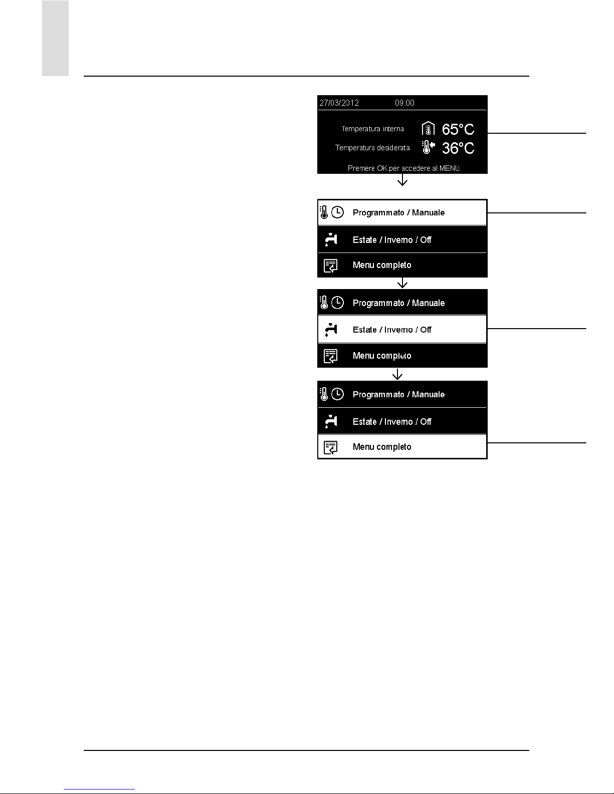
1 Schermata principale
2 Menu impostazioni di base
3 Menu completo
Schermata principale
Da questo menu è possibile visualizzare lo stato di funzionamento del sistema
e modifi care la temperatura ambiente
desiderata, semplicemente ruotando la
manopola
Menu impostazioni di base
Da questo menu è possibile accedere
alle funzioni principali: scelta tra modalità programmazione o manuale e modalità di funzionamento (estate/inverno/
off)
Menu completo
Da questo menu è possibile accedere a
tutti i principali parametri del sistema
e all’impostazione / modifi ca della programmazione oraria riscaldamento
SCHERMATA PRINCIPALE
MENU IMPOSTAZIONI DI BASE
Page 9
9
IT
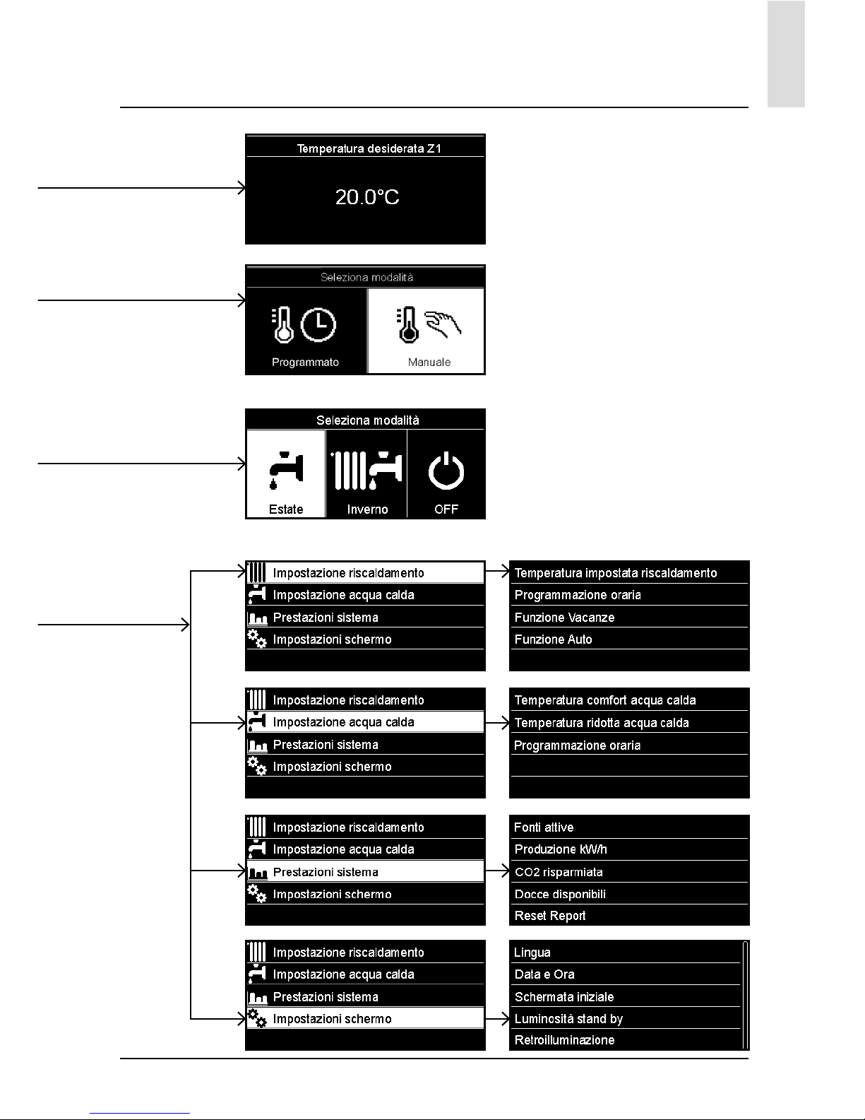
struttura menu utente
MENU COMPLETO
Page 10

10
IT
impostazioni display
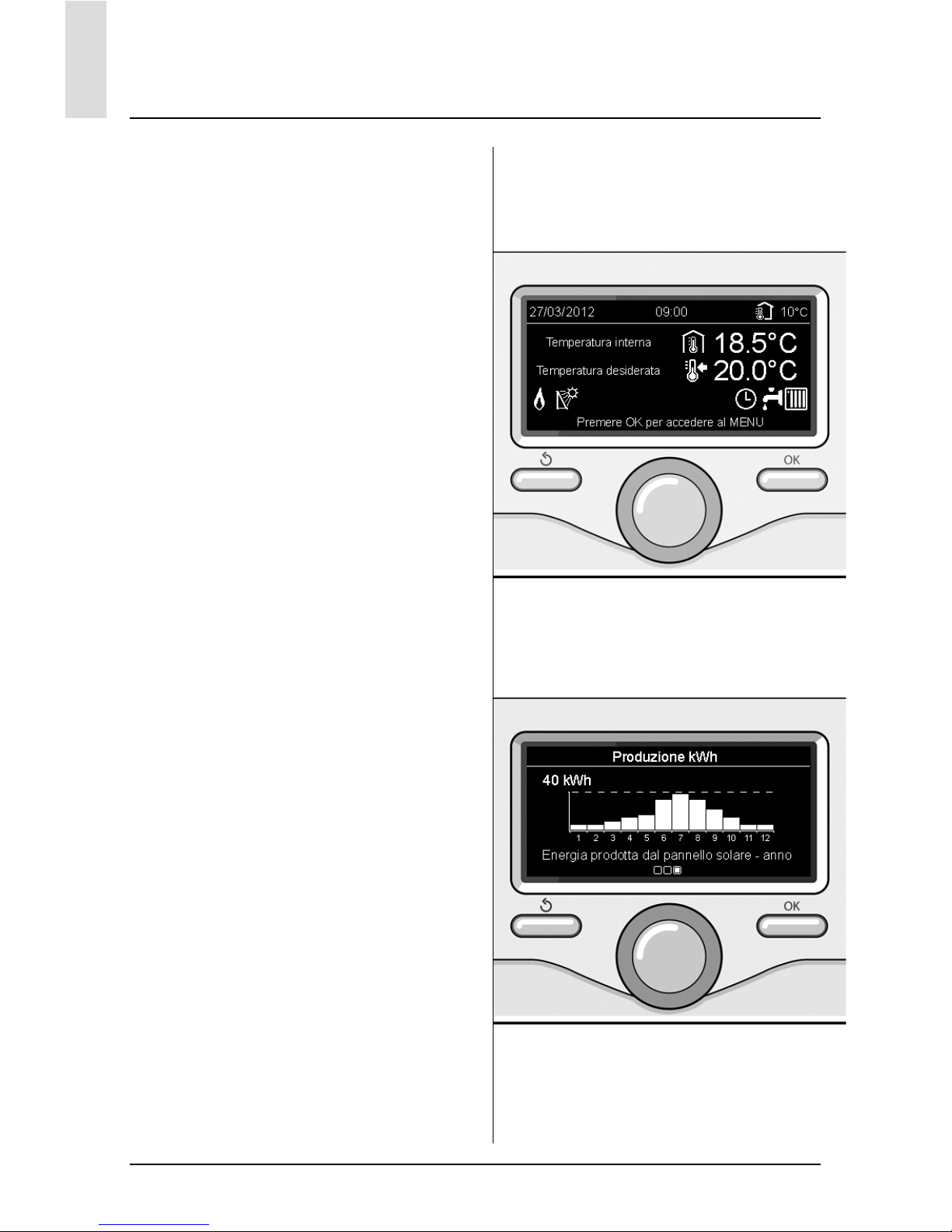
La schermata princiaple del controllo
remoto è personalizzabile. Nella schermata principale, è possibile controllare
l’ora, la data, la modalità di funzionamento della caldaia, le temperature
impostate o rilevate dall’interfaccia di
sistema, la programmazione oraria, le
fonti energetiche attive (ove presente) ed
il risparmio di emissioni di CO
2
.
Per accedere alle impostazioni del display premere il tasto OK.
Ruotare la manopola e selezionare:
- Menu completo
Premere il tasto OK.
Ruotale la manopola e selezionare:
- Impostazioni schermo
Premere il tasto OK.
Tramite il menu “Impostazioni schemo”
è possibile selezionare i seguenti parametri:
- Lingua
Premere il tasto OK.
Ruotare la manopola e selezione la
lingua desiderata.
Premere il tasto OK per comfermare la
scelta e premere il tasto indietro “
“
per ritornare alla visualizzazione precedente.
Ruotare la manopola e selezionare
- Data e ora
Premere il tasto OK.
Tramite la manopola selezionare il
giorno, premere il tasto OK, ruotare
la manopola per impostare il giorno
esatto, premere il tasto OK per confermare e passare alla selezione del
mese e successivamente dell’anno
confermando sempre l’impostazione
con il tasto OK.
Ruotale la manopola per selezionare
l’ora, premere il tasto OK, ruotare la
Visualizzazione base
Imposta data e ora
Page 11

11
IT
impostazioni display
manopola per impostare l’ora esatta,
premere il tasto OK per confermare e
passare alla selezione ed impostazio-
ne dei minuti.
Premere il tasto OK per confermare.
Ruotare la manopola e selezionare
ora legale, premere il tasto OK, se-
lezionare auto o manuale, premere il
tasto OK.
Premere il tasto OK per comfermare la
scelta e premere il tasto indietro “
“
per ritornare alla visualizzazione precedente.
Ruotare la manopola e selezionare:
- Schermata iniziale
nell’impostazione schermata iniziale
è possibile scegliere le informazioni
visualizzate.
Scegliendo la visualizzazione “Perso-
nabilzzabile” è possibile selezionare
tutte le informazioni desiderate. In alternativa è possibile scelgiere tra una
delle schermate preconfi gurate:
Base
Fonti attive
Risparmio CO2
Caldaia base
Caldaia completa
Solare (ove presente)
Zone (ove presente)
FWS (ove presente)
Premere il tasto OK per comfermare la
scelta. Premere il tasto indietro “
“per
ritornare alla visualizzazione precedente.
Ruotare la manopola e selezionare:
- Luminosità in stand-by
tramite la manopola regolare la lumi-
nosità del displayd urante i periodi di
stand-by.
Premere il tasto OK per confermare.
Ruotare la manopola e selezionare:
- Temporizzazione retroilluminazione
tramite la manopola impostare il tem-
po di retroiluminazione del display
dopo l’ultimo utilizzo dell interfaccia
di sistema viene lasciato inattivo per
un certo periodo di tempo.
Premere il tasto OK per confermare.
Ruotare la manopola e selezionare:
- Temporizzazione schermata iniziale
tramite la manopola impostare il tem-
po di attesa per la visualizzazione del-
la schermata princiapale.
Premere il tasto OK per confermare.
Premere il tasto indietro “
“ per ritor-
nare alla visualizzazione precedente.
Page 12
12
IT
modalità di funzionamento caldaia
Per selezionare la modalità di funzionamento della caldaia premere il tasto OK.
Il display visualizza:
- Programmato / Manuale
- Estate / Inverno / Off
- Menu completo
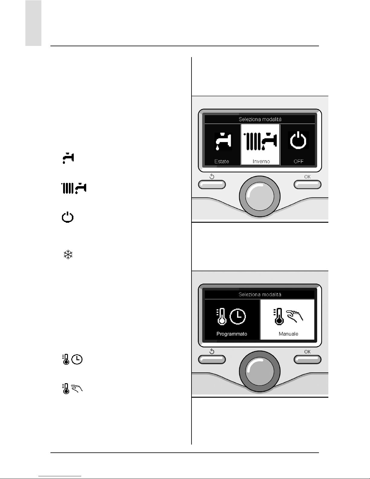
Ruotare la manopola e selezionare:
- Estate / Inverno / Off
Premere il tasto OK.
Ruotale la manopola e selezionare:
- (
) ESTATE
produzione di acqua calda sanitaria,
esclusione del riscaldamento.
- (
) INVERNO
produzione di acqua calda sanitaria e
riscaldamento.
- (
) OFF
caldaia spenta, funzione antigelo at-
tiva. Quando la funzione antigelo si
attiva il display visualizza il simbolo:
“
”. Questa funzione è una protezione contro il congelamento delle
tubature.
Premere il tasto OK per confermare.
Premere nuovamente il tasto OK per ritornare alla visualizzazione precedente.
Ruotare la manopola e selezionare:
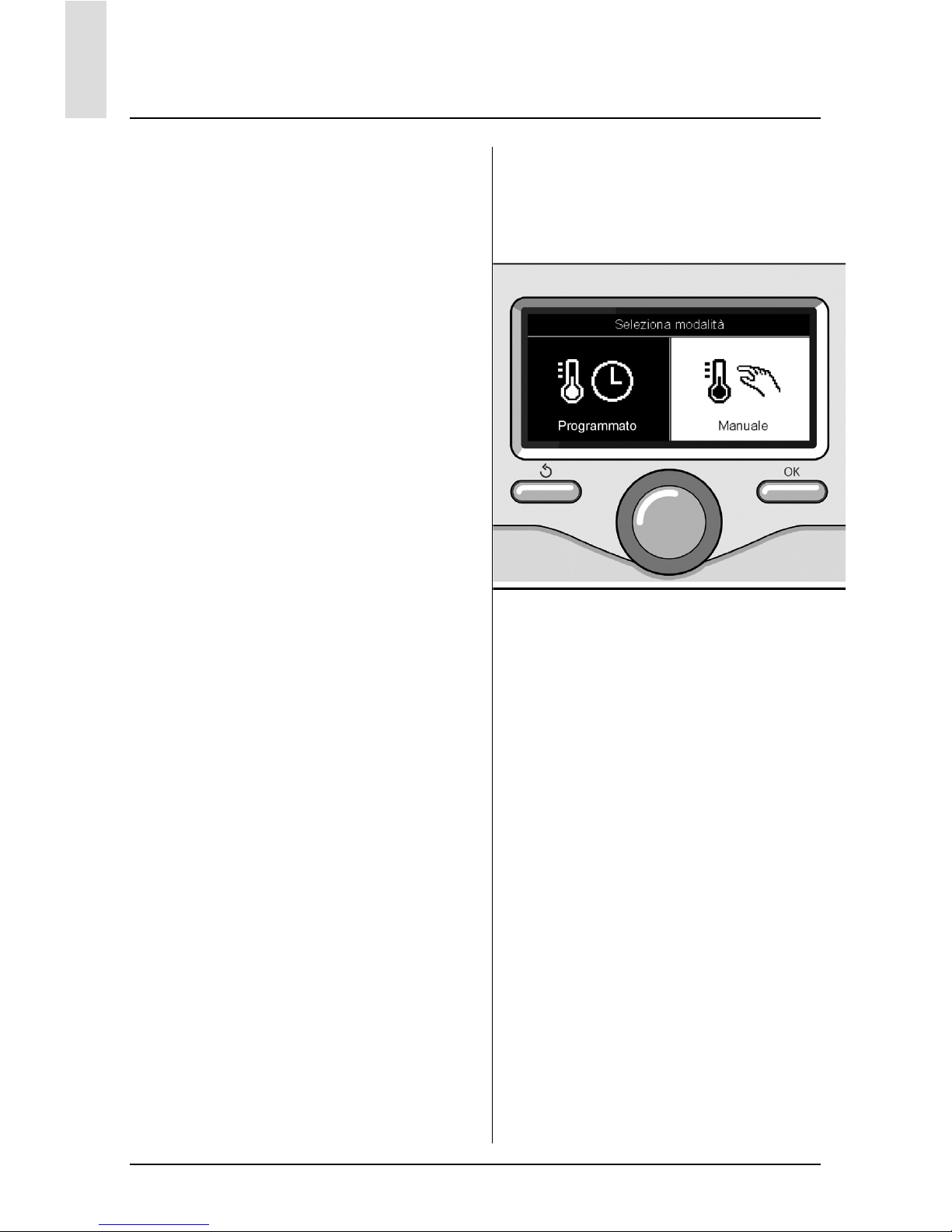
- Programmato / Manuale
Premere il tasto OK.
Ruotale la manopola e selezionare:
- (
) PROGRAMMATO
la caldaia funzionerà secondo la pro-
grammazione oraria impostata.
- (
) MANUALE
la caldaia funzionerà in modalità ma-
nuale.
Premere il tasto OK per confermare.
Premere nuovamente il tasto OK per ritornare alla visualizzazione precedente.
Selezione madalità inverno
Selezione madalità manuale
Page 13
13
IT
regolazione temperatura ambiente
In base alla modalità di funzionamento
della caldaia (Programmato/Manuale)
Vedi paragrafo “modalità di funzionamento caldaia”.
Regolazione temperatura ambiente
in modalità manuale
Ruotare la manopola per impostare il
valore di temperatura ambiente che si
desidera. Il display visualizza il valore
impostato.
Premere il tasto OK per confermare.
Il display ritorna alla visualizzazione predente.
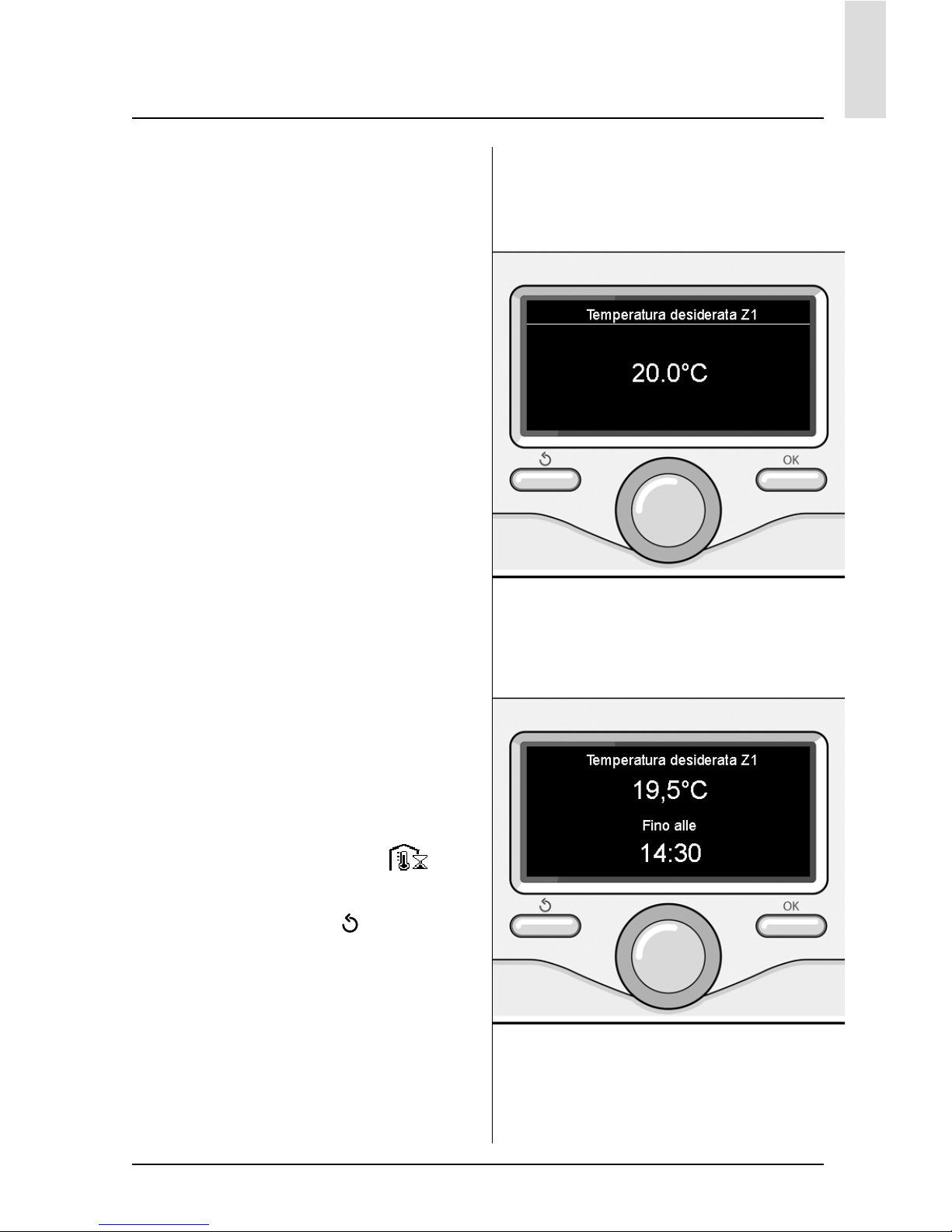
Regolazione temperatura ambiente
in modalità programmazione oraria
Durante il funzionamento della programmazione oraria è possibile modifi care temporaneamente la temperatura
ambiente impostata.
Ruotare la manopola ed impostare il valore di temperatura ambiente che si desidera. Premere il tasto OK.
Il display visualizza la temperatura impostata e l’ora fi no in cui si desidera
mantenere la modifi ca.
Ruotare la manopola per impostare l’ora
di fi ne modifi ca, premere il tasto OK per
confermare.
Il display visualizza il simbolo “
” in
corrispondenza del valore di temperatura desiderata per il periodo di modifi ca.
Premere il tasto indietro “
“ per uscire
dalla regolazione senza salvare la modifi ca.
L’interfaccia di sistema EXPERT CONTROL manterrà il valore di temperatura fi no al termine del tempo impostato,
fi nito il quale tornerà alla temperatura
ambiente pre-impostata.
Modifi ca temperatura ambiente
Modifi ca temperatura ambiente
in modalità programmazione oraria
Page 14
14
IT
impostazione acqua calda riscaldamento
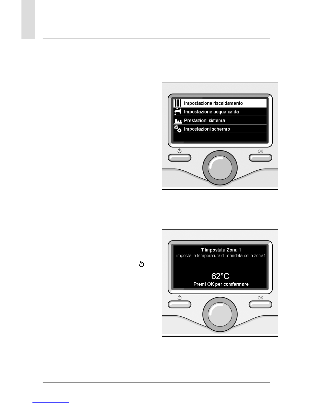
Per accedere alle impostazioni riscaldamento, premere il tasto OK.
Ruotare la manopola e selezionare:
- Menu completo
Premere il tasto OK.
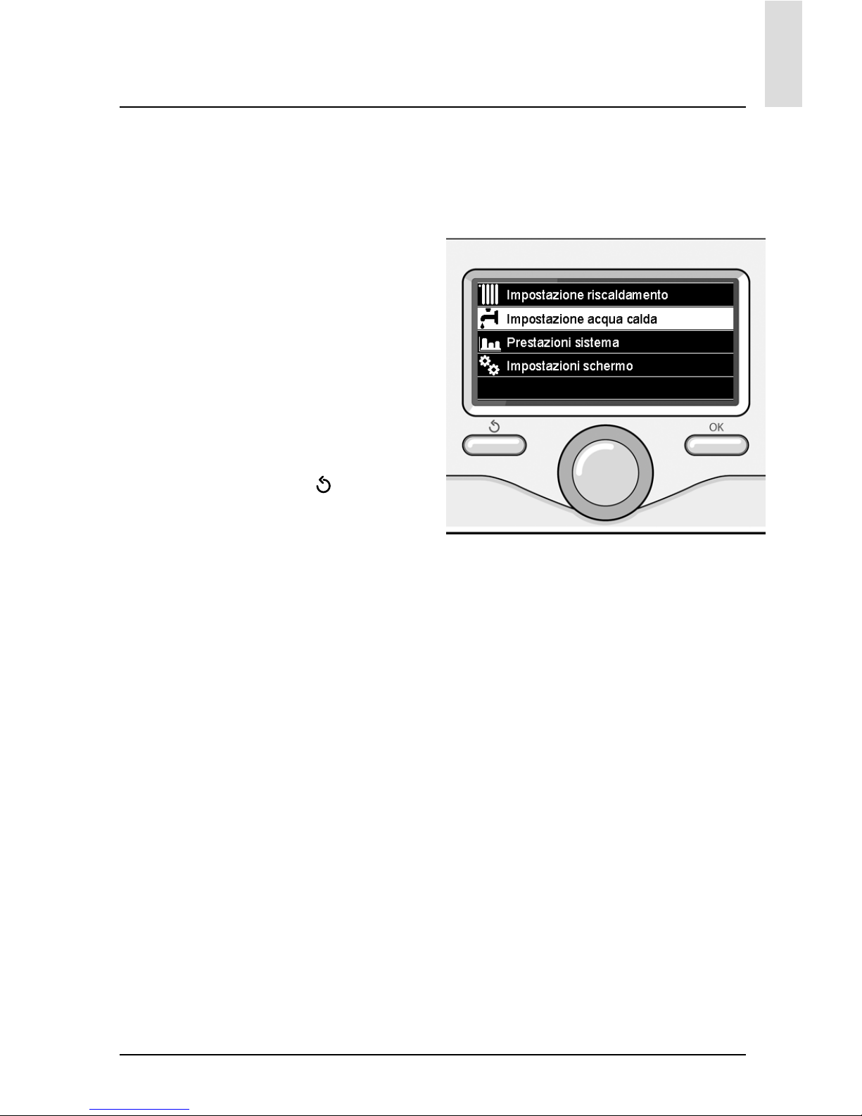
Ruotale la manopola e selezionare:
- Impostazione riscaldamento
Premere il tasto OK.
Per impostare la temperatura di mandata ruotale la manopola e selezionare:
- Temperatura impostata
riscaldamento
Premere il tasto OK.
Il display visualizza:
- T impostata Zona 1
- T impostata Zona 2
- T impostata Zona 3
Ruotale la manopola e selezionare:
- T impostata Zona 1
Premere il tasto OK.
Ruotare la manopola ed impostare la
temperatura di mandata della zona selezionata.
Premere il tasto OK per confermare.
Ripetere la procedura sopra descritta
per impostare la temperatura di mandata nelle altre zone se presenti.
Premere due volte il tasto indietro “
“.
Selezione Impostazioni riscaldamento
Modifi ca temperatura acqua calda
riscaldamento
Page 15

15
IT
programmazione oraria riscaldamento
La programmazione oraria permette
alla caldaia di riscaldare l’ambiente secondo le proprie esigenze.
Per impostare la programmazione ora-
ria del riscaldamento premere il tasto
OK. Ruotare la manopola e selezionare
- Menu completo
Premere il tasto OK.
Ruotare la manopola e selezionare:
- Impostazioni riscaldamento
Premere il tasto OK.
Il display visualizza:
- Temperatura impostata riscaldamen-
to
- Programmazione oraria
- Funzione vacanze
- Funzione Auto
Ruotare la manopola e selezionare:
- Programmazione oraria
Premere il tasto OK.
Il display visualizza:
- Programmazione libera
- Programmazione guidata
- Programmi pre-impostati
- Programmazione/manuale
Ruotare la manopola e selezionare:
- PROGRAMMAZIONE LIBERA
Premere il tasto OK.
Il display visualizza:
- Tutte le zone
- Zona 1
- Zona 2
- Zona 3
Ruotare la manopola e selezionare la
zona in cui si desidera effettuare la programmazione oraria:
Premere il tasto OK.
Ruotare la manopola e seleziona
- Imposta T Comfort
Premere il tasto OK.
Ruotare la manopola e modifi care il valore di temperatura ambiente durante il
periodo comfort (il display visualizza il
valore lampeggiante della temperatura).
Premere il tasto OK per confermare.
Ruotare la manopola e selezionare
- Imposta T Ridotta
Premere il tasto OK.
Ruotare la manopola e modifi care il valore di temperatura ambiente durante
il periodo ridotto (il display visualizza il
valore lampeggiante della temperatura).
Premere il tasto OK per confermare.
Ruotare la manopola e selezionare
- Imposta programmazione
Premere il tasto OK.
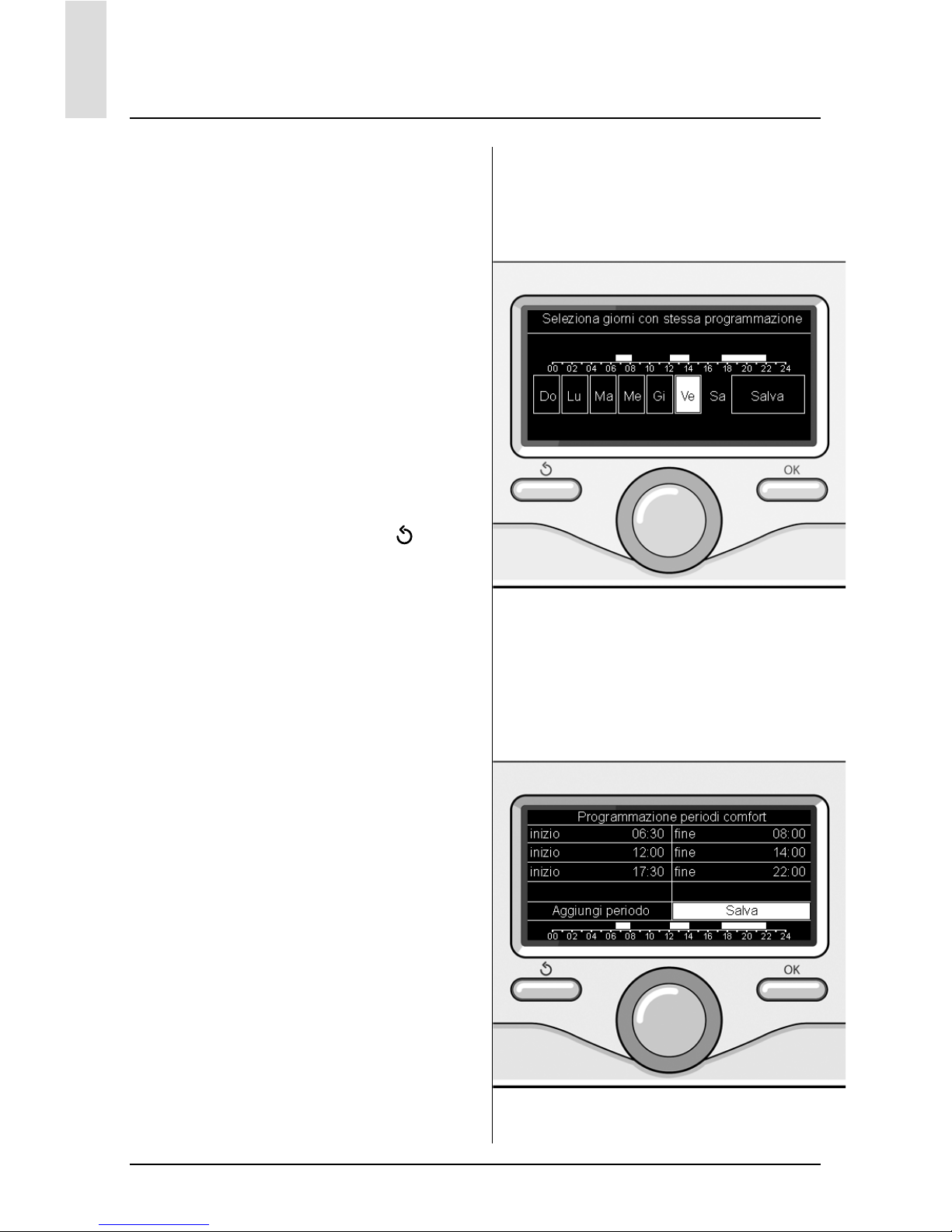
Ruotare la manopola e selezionare il
giorno o i giorni della settimana che si
desidera programmare.
Ad ogni selezione del giorno premere il
tasto OK per confermare.
Il display visualizza i giorni selezionati
per la programmazione con un riquadro.
Ruotare la manopola e selezionare salva. Premere il tasto OK e ruotare la manopola ed impostare l’inizio del periodo
di riscaldamento corrispondente al valore lampeggiante. Premere il tasto OK
per confermare.
Premere il tasto OK e ruotare la manopola per impostare l’ora di fi ne periodo
comfort.
Se si desidera aggiungere nuovi periodi
ruotare la manopola e selezionare Aggiungi periodo, prmere il tasto OK.
Ripetere la procedura sopra descritta
per impostare l’inizio e la fi ne del periodo di comfort aggiunti.
Una volta conclusa la programmazione
ruotare la manopola e selezionare Salva.
Premere il tasto OK per comfermare.
Page 16
16
IT
programmazione oraria riscaldamento
Ruotare la manopola e selezionare:
- Giorni rimanenti
nell’eventualità di giorni non ancora
programmati e ripetere le operazioni
precedentemente descritte
Ruotare la manopola e selezionare:
- Modifi ca
per modifi care eventuali periodo pre-
cedentemente programmati
Ruotare la manopola e selezionare:
- Esci
per uscire dalla impostazione pro-
grammazione oraria.
Premere il tasto OK per confermare.
Il display ritorna alla visualizzazione predente. Premere il tasto indietro “
“ per
ritornare alle visualizzazione della chermata principale.
Per facilitare le operazioni di impostazione della programmazione oraria, è
possibile eseguire la confi gurazione tramite:
- Programmazione guidata
- Programmi pre-impostati.
Ruotare la manopola e selezionare:
- PROGRAMMAZIONE GUIDATA
Premere il tasto OK.
Ruotare la manopola e selezionare la
zona in cui si desidera effettuare la programmazione oraria.
Premere il tasto OK.
Ruotare la manopola e selezionare:
- Imposta programmazione
Premere il tasto OK.
Ora seguire passo passo le indicazioni
che vengono di volta in volta visualizzate
a display.
Selezione giorni
programmazione oraria riscaldamento
Imposta periodi comfort
programmazione oraria riscaldamento
Page 17
17
IT
programmazione oraria riscaldamento
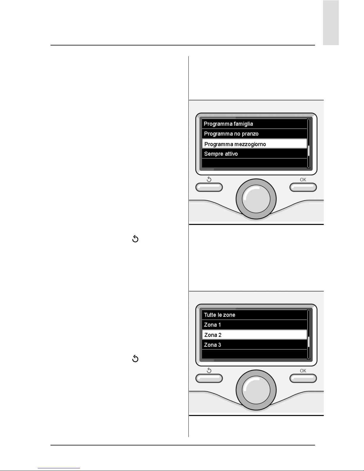
- PROGRAMMI PRE-IMPOSTATI
Premere il tasto OK.
Ruotare la manopola e selezionare la
zona in cui si desidera effettuare la programmazione oraria.
Premere il tasto OK.
Ruotare la manopola e selezionare
- Imposta programmazione
Premere il tasto OK.
Ruotare la manopola e selezionare tra:
- Programma famiglia
- Programma no pranzo
- Programma mezzogiorno
- Sempre attivo
Premere il tasto OK per comfermare.
Ruotare la manopola per scorrere i giorni e l’ora di inizio e di fi ne programma
riscaldamento.
Ruotare la manopola e selezionare salva
premere il tasto OK.
Premere il tasto indietro “
“ per ritor-
nare alle visualizzazione precedente.
- PROGRAMMATO/MANUALE
(questa modalità permette di selezionare la gestione del riscaldamento delle
zone, tra programmato o manuale)
Premere il tasto OK.
Ruotare la manopola e selezionare la
zona in cui effettuare l’impostazione.
Scelegliere tra la modalità programmazione oraria o manuale.
Premere il tasto OK.
Premere il tasto indietro “
“ per ritornare alle visualizzazione precedente
Per regolare la temperatura ambiente è
suffi ciente ruotare la manopola.
Selezione
programma mezzogiorno
Selezione modalità funzionamento
della zona 2
Page 18
18
IT
funzionamento modalità manuale riscaldamento
Selezione madalità manuale
La modalità manuale, disattiva la programmazione oraria di riscaldamento.
Il funzionamento manuale, permette di
mantenere il riscaldmanto in continuo.
Per selezionare il funzionamento della
caldaia in modalità manuale premere il
tasto OK per accedere al Menu.
Ruotare la manopola e selezionare:
- Programmato / Manuale
Premere il tasto OK.
Ruotare la manopola e selezionare:
- Manuale
Ruotare la manopola per selezionare la
modalità Manuale, premere il tasto OK.
Premere nuovamente il tasto OK per
salvare le impostazioni. Il display ritorna
alla visualizzazione predente.
Premere il tasto indietro fi no alla visualizzazione della schermata principale.
Page 19
19
IT
Selezione impostazione acqua calda
Per accedere alle impostazioni acqua
calda sanitaria, premere il tasto OK.
Ruotare la manopola e selezionare:
- Menu completo
Premere il tasto OK.
Ruotale la manopola e selezionare:
- Impostazione acqua calda
Premere il tasto OK.
Ruotale la manopola e selezionare:
- Temperatura impostata acqua calda
Premere due volte il tasto OK.
Ruotare la manopola ed impostare la
temperatura desiderata dell’acqua calda
sanitaria.
Premere il tasto OK per confermare.
Premere il tasto indietro “
“ per ritor-
nare alla visualizzazione precedente.
impostazione acqua calda sanitaria
Page 20

20
IT
programmazione oraria acqua calda sanitaria
Per impostare la programmazione ora-
ria acqua calda sanitaria premere il tasto OK.
Ruotare la manopola e selezionare
- Menu completo
Premere il tasto OK.
Ruotare la manopola e selezionare
- Impostazione acqua calda
Premere il tasto OK.
Ruotale la manopola e selezionare.
- Programmazione oraria
Premere il tasto OK.
Ruotale la manopola per selezionare:
- Programmazione libera
- Programmi pre-impostati
Ruotale la manopola per selezionare:
- Programmazione libera
Premere il tasto OK.
Ruotare la manopola e selezionare:
- Programma acqua calda
- Timer ausiliario (Modulo per la produ-
zione istantanea di acqua calda, Pom-
pa ricircolo sanitario, Elettrosolare)
In entrambi i casi ruotare la manopola
ed impostare la temperatura comfort e
ridotta, premere il tasto OK per confermare.
Ruotale la manopola per selezionare:
- Imposta programmazione
Premere il tasto OK. Per impostare la
programmazione seguire la procedura
descritta nel capitolo “programmazione
oraria riscaldamento”.
Ruotale la manopola per selezionare:
- Programmi pre-impostati
Premere il tasto OK.
Ruotare la manopola e selezionare:
- Programmazione acqua calda
- Timer ausiliario (Modulo per la produ-
zione istantanea di acqua calda, Pom-
pa ricircolo sanitario, Elettrosolare)
In entrambi i casi ruotare la manopola
ed impostare la temperatura comfort e
ridotta, premere il tasto OK per confermare.
Ruotale la manopola per selezionare:
- Imposta programmazione
Premere il tasto OK. Per impostare la
programmazione seguire la procedura
descritta nel capitolo “programmazione
oraria riscaldamento” paragrafo, programmi pre-impostati:
- Programma famiglia
- Programma no pranzo
- Programma mezzogiorno
- Sempre attivo.
Premere il tasto OK per comfermare la
scelta e premere il tasto indietro “
“per ritornare alle visualizzazione precedente.
La funzione COMFORT consente di ridurre il tempo di attesa quando si attiva
la richiesta di acqua calda sanitaria.
Per accedere alle impostazioni acqua
calda sanitaria, premere il tasto OK.
Ruotare la manopola e selezionare:
- Menu completo
Premere il tasto OK.
Ruotale la manopola e selezionare:
- Impostazione acqua calda
Premere il tasto OK.
Ruotale la manopola e selezionare:
- Funzione Comfort
Premere il tasto OK.
Ruotare la manopola e selezionare:
- Disabilitata
- Temporizzata
(secondo la programmazione oraria)
- Sempre attiva
Page 21

21
IT
funzioni speciali
Per impostare la programmazione di
una delle funzione speciali premere il
tasto OK.
Ruotare la manopola e selezionare
- Menu completo
Premere il tasto OK.
Ruotare la manopola e selezionare:
- Impostazioni riscaldamento
Premere il tasto OK.
Ruotare la manopola e selezionare:
- Funzione vacanze
- Funzione Auto
Premere il tasto OK per comfermare la
scelta.
La funzione vacanze disattiva il riscaldamento durante il periodo di vacanza.
- FUNZIONE VACANZE
Premere il tasto OK.
Ruotare la manopola e selezionare:
- ON (attiva la funzione)
- OFF (disattiva la funzione)
Premere il tasto OK.
Se si seleziona ON, ruotare la manopola per impostare la data di rientro dalle
vacanze.
Questo permetterà all’interfaccia di sistema, nella data prestabilita, di riprendere il funzionamento nella modalità
precedentemente impostata.
Premere il tasto OK per salvare le impostazioni, il display ritorna alla visualizzazione predente.
Nella schermata fonti attive, quando la
funzione vacanze è attiva, compare l’ico-
na “
”.
La funzione AUTO imposta automaticamente il regime di funzionamento della
caldaia in base al tipo di installazione e
alle condizioni ambientali.
La termoregolazione di un edifi cio consiste nel mantenerne la temperatura
interna costante al variare della temperatura esterna.
- FUNZIONE AUTO
Premere il tasto OK.
Ruotare la manopola e selezionare:
- ON (attiva la funzione)
- OFF (disattiva la funzione)
Premere il tasto OK per salvare le impostazioni, il display ritorna alla visualizzazione predente.
Nel caso in cui la temperatura dell’acqua
calda riscaldamento non corrisponda a
quella desiderata è possibile aumentarla
o diminuirla tramite parametro temperatura imposta riscaldamento.
Il display visualizza la barra di correzione.
Premere il tasto indietro “
“ per ritornare alle visualizzazione della chermata
principale.
Nella schermata fonti attive, quando la
funzione auto è attiva, compare l’icona
“
”.
Page 22
22
IT
Solare & Bollitore (ove presente)
In presenza di un impianto solare, è possibile visualizzare le prestazioni energetiche del sistema installato.
Ruotare la manopola e selezionare
- Menu completo
Premere il tasto OK.
Ruotare la manopola e selezionare
- Prestazioni sistema
Premere il tasto OK.
Ruotare la manopola e selezionare:
- Fonti attive
- Produzionw kW/h
- C02 risparmiata
- Docce disponibili
- Reset Report
Premere il tasto OK per confermare la
selezione.
- Fonti attive
Visualizza l’energia prodotta dal pan-
nello solare nell’arco di tempo che va
dalle 24h, una settimana o un anno.
- Produzione kWh
Visualizza l’energia prodotta dal pan-
nello solare nell’arco di tempo che va
dalle 24h, una settimana o un anno.
- Risparmio CO2
Visualizza il risparmio di CO2 in Kg
mettendo in relazione la distanza percorsa in auto
- Docce disponibili
Visualizza la percentuale di acqua
calda disponibile nell’accumulo e la
quantità di docce effettuabili.
- Reset Report
Resetta tutti i report.
E anche possibile visualizzare lnella
schermata principale lo schema di impianto solare installato.
Schermata fonti attive
Schermata prdduzione kWh
Page 23
23
IT
Posizionamento
L’apparecchio rileva la temperatura ambiente, quindi nella scelta della posizione di installazione vanno tenuti presenti
alcuni accorgimenti.
Posizionarlo lontano da fonti di calore
(radiatori, raggi solari, caminetti, ecc.) e
lontano da correnti d’aria o aperture verso l’esterno, le quali potrebbero infl uenzarne la rilevazione.
Installarlo a circa 1,50 m di altezza dal
pavimento.
Attenzione
L’installazione deve essere eseguita da
personale tecnico qualifi cato.
Prima del montaggio togliere la tensione alla caldaia.
Installazione a parete
Il fi ssaggio al muro dell’interfaccia di
sustema EXPERT CONTROL deve essere
effettuato prima del collegamento alla
linea BUS.
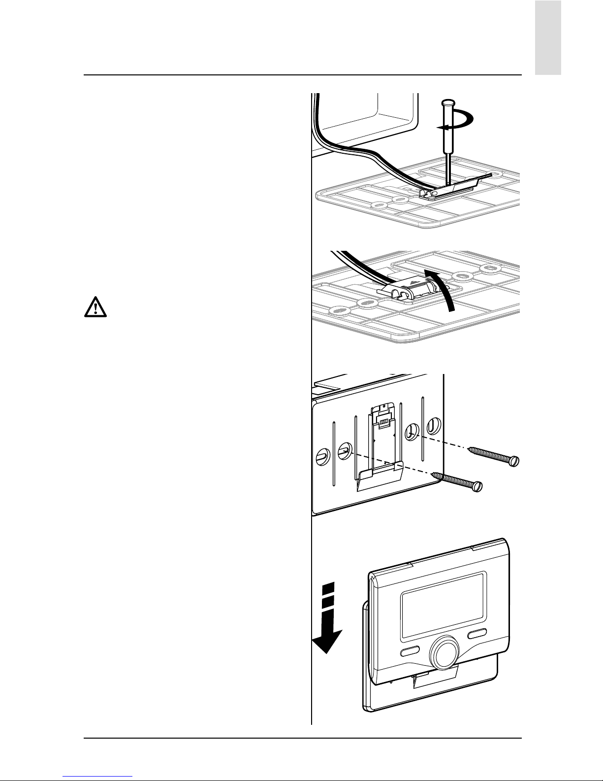
- prima di collegare i fi li alla base
dell’interfaccia di sistema, far scorrere la linguetta di protezione del connettore e sollevarla (fi g.1),
- collegare la coppia di fi li al connettore
(come spiegato nella pagina seguente) e richiudere la linguetta di protezione (fi g.2),
- aprire i fori necessari per il fi ssaggio
- fi ssare la base dell’apparecchio alla
scatola sulla parete, usando le viti fornite nel kit (fi g.3),
- posizionare l’interfaccia di sistema
sulla base, spingendola delicatamente verso il basso (fi g.4).
installazione
fi g. 1
fi g. 2
fi g. 3
fi g. 4
Page 24
24
IT
installazione
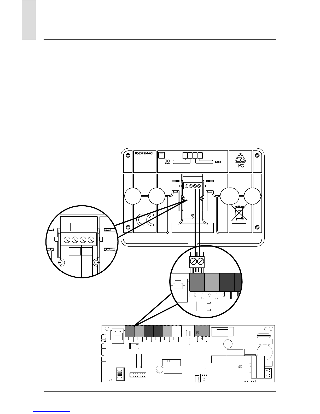
Collegamento alla caldaia
L’invio, la ricezione e la decodifi ca dei segnali avviene tramite il protocollo BUS,
che mette in comunicazione la caldaia e
l’interfaccia di sistema.
- collegare una coppia di fi li al connet-
tore BUS sulla scheda caldaia
- collegare la coppia di fi li dal connet-
tore BUS al morsetto dell’interfaccia
di sistema.
N
N
FLAME
L
L
BUS
TB
FLOOR
TA2
SE TNK SOL TA1
CN14
CN13
CN19
CN1
CN15
CN4
1
1
1
1
CN9
1
BUS
B T
BUS
TB
FLOOR
TA2
SE TNK
NOTA: Nel collegamento tra sensore
ambiente e caldaia, per evitare problemi di interferenze, utilizzare un cavo
schermato o un doppino telefonico.
SCHEDA
CALDAIA
INTERFACCIA
DI SISTEMA
Page 25
25
IT
Lingua, data e ora (Seguire le indicazioni del display, premere OK ad ogni inserimento per memorizzare)
Impostazione Rete BUS BridgeNet (lista variabile in base ai dispositivi connessi)
Controllo remoto (locale)
Controllo solare
Caldaia
Menu completo
(nelle pagine seguenti sono elencati tutti i menu/parametri disponibili)
Confi gurazione guidata (lista variabile in base ai dispositivi connessi)
Controllo solare (seguire le indicazioni riportate nella documentazione solare)
Caldaia
Parametri
Parametri Gas: 220 - 230 - 231 - 232 - 233 - 234 - 270
Parametri regolazione: 220 - 231 - 223 - 245 - 246
Visualizzazioni: 820 - 821 - 822 - 823 - 824 - 825 - 826 - 827 - 828 - 830 - 831 - 832 - 833
- 840 - 835
Zone: 402 - 502 - 602 - 420 - 520 - 620 - 434 - 534 - 634 - 830
Procedure Guidate
Riempi impianto
Disareazione impianto
Analisi Fumi
Modalità test
Test circolatore
Test valvola tre vie
Test ventilatore
Opzione Assistenza
Abilitazione Avviso di manutenzione
Reset Avviso di Manutenzione
Mesi mancanti alla manutenzione
Manutenzione
(lista variabile in base ai dispositivi connessi)
Controllo solare (seguire le indicazioni riportate nella documentazione solare)
Caldaia
Parametri
Parametri Gas: 220 - 230 - 231 - 232 - 233 - 234 - 270
Visualizzazioni: 820 - 821 - 822 - 823 - 824 - 825 - 826 - 827 - 828 - 830 - 831 - 832 - 833
- 840 - 835
Cambio scheda caldaia: 220 - 226 - 228 -229 - 230 - 231 - 232 - 233 - 234 - 247 - 250 253
Errori
Il display visualizza gli ultimi 10 errori con indicazione del codice, descrizione, data.
Ruotare la manopola per scorrere gli errori
struttura menu area tecnica
Page 26

26
IT
area tecnica
Attenzione
Per garantire la sicurezza e il corretto
funzionamento dell’interfaccia di sistema, la messa in funzione deve essere
eseguita da un tecnico qualifi cato in
possesso dei requisiti di legge.
Procedura di accensione
- Inserire l’interfaccia di sistema nella
slitta di connessione spingendolo delicatamente verso il basso, dopo una
breve inizializzazione l’interfaccia di
sistema è connessa;
- Il display visualizza ”Selezionare lin-
gua”. Ruotare la manopola e selezionare la lingua desiderata. Premere il
tasto OK per confermare.
- Il display visualizza la data e l’ora.
Tramite la manopola selezionare il
giorno, premere il tasto OK, ruotare la
manopola per impostare il giorno esatto, premere il tasto OK per confermare e passare alla selezione del mese
e successivamente dell’anno confermando sempre l’impostazione con il
tasto OK.
Ruotale la manopola per selezionare
l’ora, premere il tasto OK, ruotare la
manopola per impostare l’ora esatta,
premere il tasto OK per confermare e
passare alla selezione ed impostazione
dei minuti.
Premere il tasto OK per confermare.
Ruotare la manopola e selezionare ora
legale, premere il tasto OK, selezionare
auto o manuale, premere il tasto OK.
Il display visualizza la schermata base.
- Premere contemporaneamente i tasti
indietro “
“ e “OK” fi no alla visualizzazione sul display “Inserimento codice “.
- Ruotare la manopola per inserire il codice tecnico (234), premere il tasto OK,
il display visualizza AREA TECNICA:
- Lingua, data e ora
- Impostazione rete BUS
- Menu completo
- Confi gurazione guidata
- Manutenzione
- Errori
Ruotare la manopola e selezionare:
- IMPOSTAZIONI RETE BUS Bridgenet
Il display visualizza l’elenco dei dispositivi connessi nel sistema:
- Controllo remoto (locale)
- Controllo solare
- Caldaia
- ...
I dispositivi confi gurabili sono contrassegnati dal simbolo “
”.
Per impostare la zona corretta a cui è
associata l’interfaccia di sistema ruotare la manopola e selezionare:
- Controllo remoto (locale)
Premere il tasto OK per comfermare la
scelta e premere il tasto indietro “
“per ritornare alle visualizzazione precedente.
Ruotare la manopola e selezionare:
- MENU COMPLETO
Premere il tasto OK.
Ruotare la manopola e scorrere tra i
menu da selezionare:
0 Rete
1 Ora-Data-Lingua
2 Parametri Caldaia
3 Solare
4 Parametri Zona 1
5 Parametri Zona 2
Page 27

27
IT
6 Parametri Zona 3
7 Test & Utilità
8 Parametri Assistenza
9 Parametri Ibrido
10 Altre Periferiche
11 Free (periferiche 2° strato)
12 Free (periferiche 2° strato)
13 Free (periferiche 2° strato)
14 Zona 4
15 Zona 5
16 Zone 6
Selezionare il menu interessato, premere il tasto OK.
Ruotare la manolpola per impostare o
visualizzare il valore. Premere il tasto OK
per confermare.
Premere il tasto indietro “
“ per ritor-
nare alle visualizzazione precedente.
Per facilitare le operazioni di impostazione dei parametri, senza accedere al
Menu completo, è possibile eseguire la
confi gurazione tramite il menu di accesso rapido “Confi gurazione guidata”.
Ruotare la manopola e selezionare:
- CONFIGURAZIONE GUIDATA
Premere il tasto OK.
Ruotare la manopola e selezionare uno
tra i dispositivi visualizzati.
- Controllo Solare (ove presente)
(seguire le indicazioni riportate nella
documentazione solare)
- Caldaia
Ruotare la manopola e selezionare:
- Caldaia
Premere il tasto OK.
Ruotare la manopola e selezionare:
- Parametri
- Procedure guidate
- Modalità test
- Opzioni assistenza
Ruotare la manopola e selezionare:
- Parametri
(permette la visualizzazione e l’impostazione dei parametri essenziali per
il corretto funzionamento della caldia)
Premere il tasto OK.
Ruotare la manopola e scorrere tra i parametri da impostare:
- Parametri gas
- Parametri regolazione
- Visualizzazioni
- Zone
Premere il tasto OK per confermare.
Premere il tasto indietro “
“ per ritor-
nare alle visualizzazione precedente.
Ruotare la manopola e selezionare:
- Procedure guidate
(Le procedure guidate sono un valido
aiuto nella parametrizzazione della caldia. Ruotando la manopola si seleziona
l’elenco delle procedure che spiegano
passo passo come effettuare una corretta confi gurazione)
Premere il tasto OK.
Ruotare la manopola e scorrere tra i parametri da impostare:
- Riempimento impianto
- Disareazione impianto
- Analisi fumi
Premere il tasto OK per confermare.
Premere due il tasto indietro “
“ per
ritornare alle visualizzazione precedente
Ruotare la manopola e selezionare:
- Modalità Test
(Questa modalità permette di controllare il corretto funzionamento dei componenti in caldaia)
Premere il tasto OK.
Ruotare la manopola e selezionare il
Test da effettuare:
- Test circolatore
area tecnica
Page 28

28
IT
area tecnica
- Test valvola tre vie
- Test ventilatore
Premere il tasto OK per confermare.
Premere due il tasto indietro “
“ per ri-
tornare alle visualizzazione precedente.
Ruotare la manopola e selezionare:
- Opzioni assistenza
(Questa modalità permette di memorizzare i dati del centro assistenza e gli
avvisi di manutenzione)
Premere il tasto OK.
Ruotare la manopola e scorrere tra i parametri da impostare:
- Dati centro assistenza
- Abilitazione avvisi di manutenzione
- Reset avvisi di manutenzione
- Mesi mancanti manutenzione
Premere il tasto OK per confermare.
Premere due il tasto indietro “
“ per ri-
tornare alle visualizzazione precedente.
Ruotare la manopola e selezionare:
- MANUTENZIONE
(Nel caso si renda necessario controllare o confi gurare alcuni parametri essenziali per il corretto funzionamento della
caldaia)
Premere il tasto OK.
Ruotare la manopola e selezionare:
- Controllo Solare (ove presente)
(seguire le indicazioni riportate nella
documentazione solare)
- Caldaia
Ruotare la manopola e selezionare:
- Caldaia
Premere il tasto OK.
Ruotare la manopola e selezionare:
- Parametri
Premere il tasto OK.
Ruotare la manopola e scorrere tra i parametri:
- Parametri gas
- Visualizzazioni
- Cambio scheda caldaia
Premere il tasto OK per confermare.
Premere due il tasto indietro “
“ per ri-
tornare alle visualizzazione precedente.
Ruotare la manopola e selezionare:
- ERRORI
Premere il tasto OK.
Ruotare la manopola e selezionare:
- Controllo Solare (ove presente)
(seguire le indicazioni riportate nella
documentazione solare)
- Controllo multizona (ove presente)
- Caldaia
Premere il tasto OK.
Ruotare la manopola e selezionare
- Caldaia
Premere il tasto OK.
Ruotare la manopola per scorrere sul display gli ultimi 10 errori registrati.
Page 29

29
IT
Per impostare i parametri di termoregolazione premere contemporaneamenti i
tasti indietro “
“ e “OK” fi no alla visualizzazione sul display “Inserimento
codice“.
Ruotare la manopola per inserire il codice tecnio (234), premere il tasto OK, il
display visualizza Area tecnica.
Ruotare la manopola e selezionare
Menu completo.
Premere il tasto OK.
Ruotare la manopola e selezionare:
4 Parametri Zona 1
Premere il tasto OK.
Ruotare la manopola e selezionare:
4.2 Impostazione Zona 1
Premere il tasto OK.
Ruotare la manopola e selezionare:
4.2.0 Range T Z1
Premere il tasto OK.
Ruotare la manopola e selezionare il
range di temperatura:
0 bassa temperatura
1 alta temperatura
Premere il tasto OK. per confermare.
Ruotare la manopola e selezionare:
4.2.1 Selezione tipologia
premere il tasto OK
Ruotare la manopola ed impostare la
tipologia di termoregolazione installata:
- 0 Temperatura fi ssa di mandata
- 1 Dispositivi ON/OFF
- 2 Solo Sonda Ambiente
- 3 Solo Sonda Esterna
- 4 Sonda Ambiente + Sonda Esterna
premere il tasto OK
Ruotare la manopola e selezionare:
4.2.2 Curva Termoregolazione
premere il tasto OK
Ruotare la manopola ed impostare la
curva a seconda del tipo di impianto di
riscaldamento e premere il tasto OK.
- impianto a bassa temperatura
(pannelli a pavimento)
curva da 0,2 a 0,8
- impianto ad alta temperatura
(radiatori)
curva da 1,0 a 3,5
La verifi ca dell’idoneità della curva scelta richiede un tempo lungo nel quale
potrebbero essere necessari alcuni aggiustamenti.
Al diminuire della temperatura esterna
(inverno) si possono verifi care tre condizioni:
1. la temperatura ambiente diminuisce,
questo indica che bisogna impostare
un curva con maggiore pendenza
2. la temperatura ambiente aumenta
questo indica che bisogna impostare
una curva con minore pendenza
3. la temperatura ambiente rimane costante, questo indica che la curva impostata ha la pendenza giusta
Trovata la curva che mantiente costante
la temperatura ambiente bisogna verifi care il valore della stessa
Ruotare la manopola e selezionare:
4.2.3 Spostamento Parallelo
premere il tasto OK.
Ruotare la manopola ed impostare il valore più idoneo. Premere il tasto OK per
confermare.
NOTA:
Se la temperatura ambiente risulta
maggiore del valore desiderato bisogna
traslare parallelamente la curva verso
il basso. Se invece la temperatura ambiente risulta minore bisogna traslarla
parallelamente verso l’alto. Se la temperatura ambiente corrisponde a quella
desiderata la curva è quella esatta.
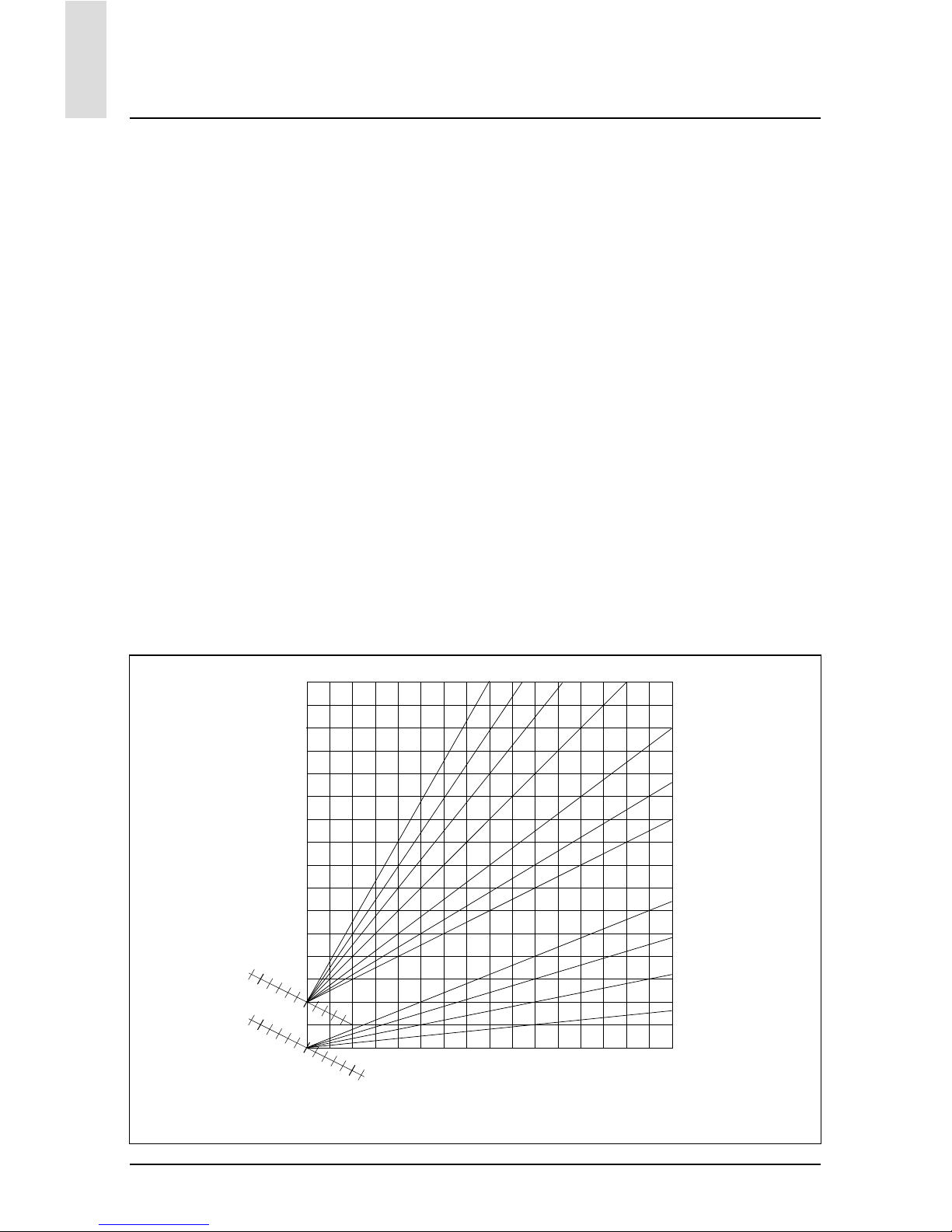
Nella rappresentazione grafi ca sotto ri-
termoregolazione
Page 30
30
IT
portata, le curve sono divise in due gruppi:
- impianti a bassa temperatura
- impianti ad alta temperatura
La divisione dei due gruppi è data dal differente punto di origine delle curve che
per l’alta temperatura è di + 10°C, correzione che abitualmente viene data alla
temperatura di mandata di questo tipo di
impianti, nella regolazione climatica.
Ruotare la manopola e selezionare:
4.2.4 Infl uenza Ambiente Proporzionale
premere il tasto OK.
Ruotare la manopola ed impostare il valore più idoneo e premere il tasto OK.
L’infl uenza della sonda ambiente è re-
temperatura di mandata all’impianto
bassa tempertaura alta tempertaura
temperatura esterna
valore di consegna
temperatura ambiente
°C
20
25
15
30
40
50
60
70
80
90
100°C
10
2.53.03.5 2.0
1.5
1.2
1.0
0.8
0.6
0.4
0.2
5 0 -5 -10 -15 -20 °C
grafi co famiglia curve
golabile tra 20 (massima infl uenza) e
0 (infl uenza eslcusa). In questo modo
è possibile regolare il contributo della
temperatra ambiente nel calcolo dellla
temperatura di mandata.
Ruotare la manopola e selezionare:
4.2.5 Temperatura massima mandata
premere il tasto OK.
Ruotare la manopola ed impostare il valore più idoneo e premere il tasto OK
Ruotare la manopola e selezionare:
4.2.6 Temperatura minima mandata
premere il tasto OK
Ruotare la manopola ed impostare il valore più idoneo e premere il tasto OK.
Ripetere le operazioni descritte per impostare i valori delle zone 2 e 3 selezionando il menu 5 e 6.
termoregolazione
Page 31

31
menu - impostazioni
IT
MENU
SOTTO-MENU
PARAMETRO
DESCRIZIONE RANGE NOTE
0 RETE
0 2 Rete BUS
0 2 0 Rete BUS attuale
Caldaia
Interfaccia di sistema
Controllo solare
Multi funzione
Energy Manager
Energy Manager ibrido
Gestore cascate
Pompa di calore
Sensore ambiente
Controllo multi zona
Modem remoto
Clip multi funzione
Fresh Water Station
Controllo piscine
Interfaccia utente
Controllo multi stanza
0 3 Interfaccia di sistema
0 3 0 Numero zona
Nessuna zona selezionata
Zona selezionata
0 3 1 Correzione temperatura ambiente
032Versione SW interfaccia
0 4 Display caldaia
0 4 0 Zona da impostare da display
041Temporizzazione backlight
0 4 2 Disattiva tasto di termoregolazione
2 PARAMETRI CALDAIA
2 0 Impostazioni Generali
2 0 0 Impostazioni temperatura sanitario
2 1 Parametri generici
Page 32

32
menu - impostazioni
IT
MENU
SOTTO-MENU
PARAMETRO
DESCRIZIONE RANGE NOTE
210Parametri generici caldaia
2 2 Impostazioni
2 2 0 Livello Lenta Accensione
2 2 1 Alto rapporto modulazione ON - OFF
2 2 2 Modulazione ventilatore
0. Esclusa
1. Attiva
223Termostato Pavimento o TA2
0. Termostato Pavimento
1. Termostato Ambiente2
224Termoregolazione
0. Assente
1. Presente
2 2 5 Ritardo Partenza Riscaldamento
0. Disabilitata
1. 10 sec
2. 90 sec
3. 210 sec
2 2 6 Confi gurazione caldaie convenzionali
0. Mono camera aperta
1. Mono camera aperta VMC
2. Mono camera stagna
ventilatore fi sso
3. Mono camera stagna
ventilatore modulante
4. Bitermica camera aperta
5. Bitermica camera stagna
2 2 7 Caldaia Ibrida
0. Esclusa
1. Attiva
228Versione Caldaia
0. Mista Istantanea
1. Accumulo Ext con Sonda
NTC
2. Accumulo Ext con
Termostato
3. Microaccumulo
4. Accumulo a Stratifi cazione
6. Storage
229Potenza nominale caldaia
Page 33

33
menu - impostazioni
IT
MENU
SOTTO-MENU
PARAMETRO
DESCRIZIONE RANGE NOTE
2 3 Riscaldamento-1
2 3 0 Livello Max Pot Riscaldamento Assoluta
2 3 1 Livello Max Pot Riscaldalmento Regolabile
232Percentuale Potenza Max Sanitario
233Percentuale Potenza min
234Percentuale Potenza Max Riscaldamento
2 3 5 Tipo Ritardo di Accensione Riscaldamento
0. Manuale
1. Automatico
2 3 6 Impostazione Ritardo Accensione
237Postcircolazione Riscaldamento
238Funzionamento Circolatore
0. Bassa velocità
1. Alta velocità
2. Modulante
2 3 9 DeltaT Modulazione Circolatore
2 4 Riscaldamento-2
240Pressione Minima
241Pressione Allerta
242Pressione Riempimento
243Post ventilazione Riscaldamento OFF - ON
244Tempo Incremento Temperatura Risc
2 4 5 Max PWM pompa
2 4 6 Min PWM pompa
2 4 7 Dispositivo Rilevazione Pressione Risc
0. Solo Sonde T
1. Pressostato di Minima
2. Sensore Pressione
2 4 8 Abilitazine Riempimento Semiautomatico
2 4 9 Correzione Temperatura esterna
Page 34

34
menu - impostazioni
IT
MENU
SOTTO-MENU
PARAMETRO
DESCRIZIONE RANGE NOTE
2 5 Sanitario
250Funzione Comfort
0. Disabilitata
1. Temporizzata
2. Sempre Attiva
251Tempo Anticiclaggio Comfort
2 5 2 Ritardo Partenza Sanitario
2 5 3 Logica Spegn Bruciatore Sanitario
0. Anticalcare
1. Set-point più 4°C
254Post-raffreddamento Sanitario ON - OFF
2 5 5 Ritardo San- > Risc
2 5 6 Celectic ON - OFF
257Funzione Anti-legionella ON - OFF
258Frequenza antilegionella
259Temperatura obbiettivo antilegionella
2 6 Forzamenti manuali caldaia
2 6 0 Attivazione modo manuale
0. Modo normale
1. Modo manuale
261Forzamento pompa caldaia ON - OFF
262Forzamento ventilatore ON - OFF
263Forzamento valvola deviatrice
Sanitario
Riscaldamento
264Forzamento pompa sanitaria ON - OFF
265Forzamento modulo Aerotech ON - OFF
2 7 Cicli di verifi ca
2 7 0 Spazzacamino ON - OFF
2 7 1 Ciclo Disareazione ON - OFF
2 8 Reset menu
Page 35

35
menu - impostazioni
IT
MENU
SOTTO-MENU
PARAMETRO
DESCRIZIONE RANGE NOTE
2 8 0 Ripristino Impost di Fabbrica OK = Sì, esc = No
3 SOLARE
3 0 Impostaz Generali
3 0 0 Impostazione Temperatura Accumulo
3 0 2 Impostazione Temp. Ridotta Accumulo
3 1 Statistiche Solari
3 1 0 Energia Solare
3 1 1 Energia Solare 2
312Tempo Tot ON Pompa Solare
313Tempo Tot Sovratemperatura Coll Solare
3 2 Impostazioni Solari 1
320Funzione Anti Legionella ON - OFF
3 2 1 Schema Idraulico
0. Non defi nito
1. Base mono serpentino
2. Base doppio serpentino
3. Elettrosolare
4. Integrazione riscaldamento
322Funzionamento resistenza elettrica
0. EDF
1. Temporizzata
3 2 3 DeltaT Collettore per Avvio Pompa
3 2 4 DeltaT Collettore per Stop Pompa
3 2 5 Min T Collettore per Avvio Pompa
3 2 6 Collectorkick ON - OFF
327Funzione Recooling ON - OFF
3 2 8 Setpoint Accumulo con Gas
329Temperatura Antigelo Collettore
3 3 Impostazioni Solari 2
Page 36

36
menu - impostazioni
IT
MENU
SOTTO-MENU
PARAMETRO
DESCRIZIONE RANGE NOTE
3 3 0 Impostazioni Portata Fluido
3 3 1 Gruppo Ciroclazione Digitale ON - OFF
332Presenza sensore pressione ON - OFF
333Presenza Anodo Pro-Tech ON - OFF
334Funzione Uscita AUX
0. Richiesta integrazione
1. Allarme
2. Pompa de-stratifi cazione
3 3 5 Delta T obbiettivo x modulazione
336Frequenza antilegionella
337Temperatura obbiettivo antilegionella
338Parametro generico solare
339Parametro generico solare
3 4 Modo Manuale
3 4 0 Attivazione Modo Manuale ON - OFF
3 4 1 Attiva Pompa Solare ON - OFF
3 4 2 Attiva Valvola 3 vie ON - OFF
3 4 3 Attiva Uscita AUX ON - OFF
3 4 4 Attiva Uscita Out ON - OFF
3 4 5 Controllo valvola Mix
0. ON
1. Aperto
2. Chiuso
3 5 Diagnostica Solare 1
350Temperatura Collettore Solare
3 5 1 Sonda Bassa Bollitore
3 5 2 Sonda Alta Bollitore
353Temperatura Ritorno Riscaldamento
3 5 4 Sonda ingresso collettore
Page 37

37
menu - impostazioni
IT
MENU
SOTTO-MENU
PARAMETRO
DESCRIZIONE RANGE NOTE
3 5 5 Sonda uscita collettore
3 6 Diagnostica Solare 2
360Portata Circuito Solare
361Pressione Circuito Solare
3 6 2 Capacità Accumulo
0. Non defi nito
1. 150 l
2. 200 l
3. 300 l
3 6 3 Numero Docce Disponibili
364% Riempimento Bollitore
3 8 Storico Errori
3 8 0 Ultimi 10 Errori
3 8 1 Reset Lista Errori Reset? OK=Si, esc=No
3 9 Reset Menu
3 9 0 Ripristino Impostazioni Fabbrica
4 PARAMETRI ZONA 1
4 0 Impostazione Temperature
400Temperatura Giorno
401Temperatura Notte
402Temperatura set Z1
403Temperatura antigelo zona
4 1 Parametri generici
410Parametro generico zona
411Parametro generico zona
412Parametro generico zona
4 2 Impostaz Zona1
Page 38

38
menu - impostazioni
IT
MENU
SOTTO-MENU
PARAMETRO
DESCRIZIONE RANGE NOTE
4 2 0 Range Temperatura
0. Bassa Temperatura
1. Alta Temperatura
4 2 1 Selezione Tipologia Termoregolazione
0.
Temperatura Fissa di Mandata
1. Dispositivi ON/OFF
2. Solo Sonda Ambiente
3. Solo Sonda Esterna
4. Sonda Ambiente +
Sonda Esterna
4 2 2 Curva Termoregolazione
4 2 3 Spostamento Parallelo
424Infl uenza Ambiente Proporzionale
4 2 5 Max T
4 2 6 Min T
4 2 7 Tipologia Circuito Riscaldamento
0. Termosifoni Veloci
1. Termosifoni Medi
2. Termosifoni Lenti
3. Impianto Pavimento Veloce
4. Impianto Pavimento Medio
5. Impianto Pavimento Lento
6. Controllo Ambiente solo
Proporzionale
4 2 8 Max azione Integrale su sensore ambiente HYD
4 3 Diagnostica Zona1
430Temperatura Ambiente
431Temperatura Set ambiente
432Temperatura mandata
433Temperatura ritorno
434Stato Richiesta Calore Z1 ON - OFF
435Stato Pompa ON - OFF
4 4 Dispositivi Zona1
Page 39

39
menu - impostazioni
IT
MENU
SOTTO-MENU
PARAMETRO
DESCRIZIONE RANGE NOTE
4 4 0 Zone pump modulation
0. Velocità fi ssa
1. Modulante su deltaT
2. Modulante su pressione
4 4 1 DeltaT obbiettivo per modulazione
442Velocità fi ssa pompa
5 PARAMETRI ZONA 2
5 0 Imposta Temperature
500Temperatura Giorno
501Temperatura Notte
502Temperatura Zona 2
503Temperatura Antigelo zona
5 1 Parametri generici
510Parametro generico zona
511Parametro generico zona
512Parametro generico zona
5 2 Impostazioni Zona 2
5 2 0 Range Temperatura
0. Bassa Temperatura
1. Alta Temperatura
5 2 1 Selezione Tipologia Termoregolazione
0.
Temperatura Fissa di Mandata
1. Dispositivi ON/OFF
2. Solo Sonda Ambiente
3. Solo Sonda Esterna
4. Sonda Ambiente +
Sonda Esterna
5 2 2 Curva Termoregolazione
5 2 3 Spostamento Parallelo
524Infl uenza Ambiente Proporzionale
5 2 5 Max T
5 2 6 Min T
Page 40

40
menu - impostazioni
IT
MENU
SOTTO-MENU
PARAMETRO
DESCRIZIONE RANGE NOTE
5 2 7 Tipologia Circuito Riscaldamento
0. Termosifoni Veloci
1. Termosifoni Medi
2. Termosifoni Lenti
3. Impianto Pavimento Veloce
4. Impianto Pavimento Medio
5. Impianto Pavimento Lento
6. Controllo Ambiente solo
Proporzionale
5 2 8 Max azione Integrale su sensore ambiente HYD
5 3 Diagnostica Zona 2
530Temperatura Ambiente
531Temperatura Set ambiente
532Temperatura mandata
533Temperatura ritorno
534Stato Richiesta Calore Z2 ON - OFF
535Stato Pompa ON - OFF
5 4 Dispositivi Zona 2
5 4 0 Zone pump modulation
0. Velocità fi ssa
1. Modulante su delta T
2. Modulante su pressione
5 4 1 DeltaT obbiettivo per modulazione
542Velocità fi ssa pompa
6 PARAMETRI ZONA 3
6 0 Imposta Temperature
600Temperatura Giorno
601Temperatura Notte
602Temperatura Zona 2
603Temperatura Antigelo zona
6 1 Parametri generici
Page 41

41
menu - impostazioni
IT
MENU
SOTTO-MENU
PARAMETRO
DESCRIZIONE RANGE NOTE
610Parametro generico zona
611Parametro generico zona
612Parametro generico zona
611
Impostazioni Zona 3
6 1 2 Range Temperatura
0. Bassa Temperatura
1. Alta Temperatura
6 1 3 Selezione Tipologia Termoregolazione
0.
Temperatura Fissa di Mandata
1. Dispositivi ON/OFF
2. Solo Sonda Ambiente
3. Solo Sonda Esterna
4. Sonda Ambiente +
Sonda Esterna
6 1 4 Curva Termoregolazione
6 1 5 Spostamento Parallelo
6 2 Impostazioni Zona 3
6 2 0 Max T
6 2 1 Min T
6 2 2 Tipologia Circuito Riscaldamento
0. Termosifoni Veloci
1. Termosifoni Medi
2. Termosifoni Lenti
3. Impianto Pavimento Veloce
4. Impianto Pavimento Medio
5. Impianto Pavimento Lento
6. Controllo Ambiente solo
Proporzionale
6 2 3 Max azione Integrale su sensore ambiente HYD
624Infl uenza Ambiente Proporzionale
6 2 5 Max T
6 2 6 Min T
Page 42

42
menu - impostazioni
IT
MENU
SOTTO-MENU
PARAMETRO
DESCRIZIONE RANGE NOTE
6 2 7 Tipologia Circuito Riscaldamento
Termosifoni Veloci
Termosifoni Medi
Termosifoni Lenti
Impianto Pavimento Veloce
Impianto Pavimento Medio
Impianto Pavimento Lento
Controllo Ambiente solo Proporzionale
6 2 8 Max azione Integrale su sensore ambiente
6 3 Diagnostica Zona 3
630Temperatura Ambiente
631Temperatura Set ambiente
632Temperatura mandata
633Temperatura ritorno
634Stato Richiesta Calore Z3 ON - OFF
635Stato Pompa ON - OFF
6 4 Dispositivi Zona3
6 4 0 Zone pump modulation
0. Velocità fi ssa
1. Modulante su delta T
2. Modulante su pressione
6 4 1 DeltaT obbiettivo per modulazione
642Velocità fi ssa pompa
7 MODULO DI ZONA
7 1 Modo Manuale
7 1 0 Attivazione modo manuale ON - OFF
7 1 1 Controllo pompa Z1 ON - OFF
7 1 2 Controllo pompa Z2 ON - OFF
7 1 3 Controllo pompa Z3 ON - OFF
Page 43

43
menu - impostazioni
IT
MENU
SOTTO-MENU
PARAMETRO
DESCRIZIONE RANGE NOTE
7 1 4 Controllo valvola mix Z2
0. OFF
1. Aperto
2. Chiuso
7 1 5 Controllo valvola mix Z3
0. OFF
1. Aperto
2. Chiuso
7 2 Modulo di zona
7 2 0 Schema idraulico
0. Non defi nito
1. MCD
2. MGM II
3. MGM III
4. MGZ I
5. MGZ II
6. MGZ III
7 2 1 Correzione T Mandata
722Funzione uscita AUX
0. Richiesta Calore
1. Pompa esterna
2. Allarme
7 2 3 Correzione Temperatura Esterna
7 3 Parametri generici
730Parametro generico modulo zona
731Parametro generico modulo zona
732Parametro generico modulo zona
7 4 Modo Manuale 2
7 4 0 Attivazione modo manuale ON - OFF
7 4 1 Controllo pompa Z1 ON - OFF
7 4 2 Controllo pompa Z2 ON - OFF
7 4 3 Controllo pompa Z3 ON - OFF
7 4 4 Controllo valvola mix Z2
0. OFF
1. Aperto
2. Chiuso
Page 44

44
menu - impostazioni
IT
MENU
SOTTO-MENU
PARAMETRO
DESCRIZIONE RANGE NOTE
7 4 5 Controllo valvola mix Z3
0. OFF
1. Aperto
2. Chiuso
7 5 Modulo di zona 2
7 5 0 Schema idraulico
0. Non defi nito
1. MCD
2. MGM II
3. MGM III
4. MGZ I
5. MGZ II
6. MGZ III
7 5 1 Correzione T Mandata
752Funzione uscita AUX
0. Richiesta Calore
1. Pompa esterna
2. Allarme
7 5 3 Correzione Temperatura Esterna
7 6 Parametri generici 2
760Parametro generico zona
761Parametro generico zona
762Parametro generico zona
7 8 Storico errori
7 8 0 Ultimi 10 errori
7 8 1 Reset Lista Errori Resettare? OK=Sì, esc=No
7 8 2 Ultimi 10 errori 2
7 8 3 Reset Lista Errori 2 Resettare? OK=Sì, esc=No
7 9 Reset Menu
7 9 0 Ripristino Impost di Fabbrica Resettare? OK=Sì, esc=No
7 9 1 Ripristino Impost di Fabbrica 2 Resettare? OK=Sì, esc=No
Page 45

45
menu - impostazioni
IT
MENU
SOTTO-MENU
PARAMETRO
DESCRIZIONE RANGE NOTE
8 PARAMETRI ASSISTENZA
8 1 Statistiche
810Ore Bruciatore ON Risc (h x10)
811Ore Bruciatore ON San (h x10)
8 1 2 Nr Distacchi Fiamma (n x10)
8 1 3 Nr Cicli Accensione (n x10)
8 1 4 Durata Media Richieste Calore
8 1 5 Numero Cicli Riempimento
8 2 Caldaia
8 2 0 Livello Modulazione Bruciatore
821Stato Ventilatore ON - OFF
822Velocità Ventilatore x100RPM
8 2 3 Livello Velocità Pompa
0. OFF
1. Velocità bassa
2. Velocità alta
824Posizione Valvola Deviatrice
0. Sanitario
1. Riscaldamento
825Portata Sanitario l/min
826Stato Pressostato Fumi
0. Aperto
1. Chiuso
827% Modulazione pompa
828Potenza istantanea
8 3 Temperature Caldaia
830Temp Impostata Riscaldamento
831Temperatura Mandata Riscaldamento
832Temperatura Ritorno Riscaldamento
833Temperatura Misurata Sanitario
Page 46

46
menu - impostazioni
IT
MENU
SOTTO-MENU
PARAMETRO
DESCRIZIONE RANGE NOTE
834Temperatura Fumi
835Temperatura esterna
8 4 Solare & Bollitore
840Temperatura Misurata Accumulo
841Temperatura Collettore Solare
842Temperatura Ingresso Sanitario
8 4 3 Sonda Bollitore Bassa
844Temperatura Set Bollitore Stratifi cazione
8 5 Service
8 5 0 Mesi Mancanti Alla Manutenzione
8 5 1 Abilitazione Avvisi Manutenzione ON - OFF
8 5 2 Cancellazione Avvisi Manutenzione Cancellare? OK=Sì, esc=No
853Stato Intasamento Scambiatore Sanitario
0. Scambiatore Sanitario OK
1. Parzialmente Intasato
2. Molto intasato Da sostituire
854Versione HW Scheda
855Versione SW Scheda
856Stato Carica Vaso Espansione
0. Da Ricaricare
1. OK
8 6 Storico errori
8 6 0 Ultimi 10 errori
8 6 1 Reset Lista Errori Reset? OK=Sì, esc=No
8 7 Parametri generici
870Parametro generico caldaia zona
871Parametro generico caldaia zona
472Parametro generico caldaia zona
Page 47

47
menu - impostazioni
IT
MENU
SOTTO-MENU
PARAMETRO
DESCRIZIONE RANGE NOTE
9 PARAMETRI IBRIDO
9 0 User Parameters
900Eco / Comfort
0. Eco Plus
1. Eco
2. Medio
3. Comfort
4. Comfort Plus
HYB
901Forzamento manuale PdC/Caldaia
0. Auto
1. Solo Caldaia
2. Solo PdC
HYB
9 1 Statistiche Energy Manager
910PdC ore di funzionamento (h/10)
911PdC n. Cicli Accensione (n/10)
912PdC n. Cicli sbrinamento (n/10)
913PdC+Caldaia ore di funzionamento (h/10)
9 2 Costi dell'energia 1
920Temp Est. x Disabilitazione Caldaia
921Temp Est. x Disabilitazione PdC
9 2 2 OFFSET Max Temp Impostabile PdC
9 2 3 Limitazione Freq compressore HP
9 2 4 Min Rapporto Costo Elettricità/Gas
9 2 5 Max Rapporto Costo Elettricità/Gas
9 2 6 Rapporto Energia Primaria /Energia Elec
9 2 7 Logica Energy Manager
0. Massimo Risparmio
1. Massima Ecologia
928Temp. ambiente set-mis x ON caldaia
9 3 Costi dell'energia 2
9 3 0 Modo Notturno PdC ON - OFF
Page 48

48
menu - impostazioni
IT
MENU
SOTTO-MENU
PARAMETRO
DESCRIZIONE RANGE NOTE
931Ora Inizio Modo Notturno PdC [hh:mm]
932Ora Fine Modo Notturno PdC [hh:mm]
9 3 3 Costo kWh gas (PCS)
9 3 4 Costo kWh elettricità
9 3 5 Costo kWh elettricità tariffa ridotta
936Parametro generico energy manager
937Parametro generico energy manager
938Parametro generico energy manager
9 4 Temperature PdC
940Temperatura esterna
941Temperatura mandata PdC
942Temperatura ritorno PdC
943Temperatura evaporatore PdC
944Temperatura gas PdC
945PdC Temperatura Condensatore (ICT)
9 5 Stato PdC
950Frequenza misurata compressore
9 5 1 Modulazione richiesta al compressore
9 5 2 Modulazione calcolata caldaia
9 5 3 Modo di funzionamento PdC
0. Stand-by
1. Non presente
2. Modo caldo
3. Sbrinamento
954PdC Errore presente Scheda ODU
955PdC Errore presente Scheda HYDI
956PdC Codice Errore Scheda ODU
Page 49

49
menu - impostazioni
IT
MENU
SOTTO-MENU
PARAMETRO
DESCRIZIONE RANGE NOTE
957PdC Codice Errore Scheda HYDI
958Stato Energy Manager
9 6 Info Energy Manager
9 6 0 Costo attuale KWh da PdC
9 6 1 Costo attuale KWh da Caldaia
9 6 2 Costo stimato KWh da PdC
9 6 3 Costo stimato KWh da Caldaia
964Temperatura Mandata Riscaldamento
965Temperatura Ritorno Riscaldamento
966Stato Pompa Riscaldamento
0. Spenta
1. Accesa
9 7 Cicli di verifi ca HP
970Forza modo deice PdC ON - OFF
971Forza compressore PdC freq fi ssa ON - OFF
9 8 Storico errori
9 8 0 Ultimi 10 errori
9 8 1 Reset Lista Errori Reset? OK=Sì, esc=No
9 9 Reset Menu
9 9 0 Ripristino Impost di Fabbrica Reset? OK=Sì, esc=No
10 FRESH WATER STATION
10 0 Parametri utente
10 0 0 Impostazione Temperatura Accumulo
10 1 Modo Manuale
10 1 0 Attivazione modo manuale ON - OFF
10 1 1 Attiva pompa solare ON - OFF
Page 50

50
menu - impostazioni
IT
MENU
SOTTO-MENU
PARAMETRO
DESCRIZIONE RANGE NOTE
10 1 2 Attiva valvola 3 vie ON - OFF
10 1 3 Attiva uscita AUX ON - OFF
10 1 4 Controllo valvola mix
0. OFF
1. Aperto
2. Chiuso
10 2 Parametri FWS
10 2 0 Schema Idraulico
0. Non defi nito
1. Senza pompa ricircolo sanit
2. Con pompa ricircolo sanit
10 2 1 Tipo pompa circolazione sanitario
0. Temporizzata
1. Dopo prelievo
10 2 2 Parametro generico FWS
10 2 3 Parametro generico FWS
10 2 4 Parametro generico FWS
10 3 Diagnostica FWS
10 3 0 Temperatura uscita sanitario
10 3 1 Temperatura ingresso Sanitario
10 3 2 Temperatura Ritorno Riscaldamento
10 3 3 Temperatura Mandata Riscaldamento
10 3 4 Portata Sanitario
10 3 5 Sonda Bollitore Bassa
10 3 6 Consumo sanitario totale
10 3 7 Tempo Totale ON Pompa FWS
11 SCHEDINO MULTIFUNZIONE
11 0 Generale
Page 51

51
menu - impostazioni
IT
MENU
SOTTO-MENU
PARAMETRO
DESCRIZIONE RANGE NOTE
11 0 0 Selezione funzione
0. Non defi nito
1. 3 zone dirette
2. Notifi ca errori e reset
3. Termostato differenziale
4. Termostato
5. Uscita temporizzata
11 0 1 Attivazione modo manuale ON - OFF
11 0 2 Controllo OUT1 ON - OFF
11 0 3 Controllo OUT2 ON - OFF
11 0 4 Controllo OUT3 ON - OFF
11 1 Diagnostica
11 1 0 Temperatura IN1
11 1 1 Temperatura IN2
11 1 2 Temperatura IN3
11 1 3 Stato OUT1
11 1 4 Stato OUT2
11 1 5 Stato OUT3
11 2 Termostato differenziale
11 2 0 Differenziale accensione termostato
11 2 1 Differenziale spegnimento termostato
11 2 2 Massima temperatura IN1
11 2 3 Massima temperatura IN2
11 2 4 Minima temperatura IN1
11 3 Termostato
11 3 0 Temperatura impostata termostato
11 3 1 Isteresi termostato
11 4 Parametri generici
Page 52

52
menu - impostazioni
IT
MENU
SOTTO-MENU
PARAMETRO
DESCRIZIONE RANGE NOTE
10 4 0 Parametro generico multifunzionale
10 4 1 Parametro generico multifunzionale
10 4 2 Parametro generico multifunzionale
10 4 3 Parametro generico multifunzionale
10 4 4 Parametro generico multifunzionale
10 4 5 Parametro generico multifunzionale
10 4 6 Parametro generico multifunzionale
14 PARAMETRI ZONA 4
14 0 Impostazione Temperature
14 0 0 Temperatura Giorno
14 0 1 Temperatura Notte
14 0 2 Temperatura set Z4
14 1 Parametri generici
14 1 0 Parametro generico zona
14 1 1 Parametro generico zona
14 2 Impostazione Zona 4
14 2 0 Range Temperatura Zona 4
0. Bassa Temperatura
1. Alta Temperatura
14 2 1 Selezione tipologia termoregolazione
0.
Temperatura Fissa di Mandata
1. Dispositivi ON/OFF
2. Solo Sonda Ambiente
3. Solo Sonda Esterna
4. Sonda Ambiente +
Sonda Esterna
14 2 2 Curva Termoregolazione
14 2 3 Spostamento Parallelo
14 2 4 Infl uenza Ambiente Proporzionale
14 2 5 Max Temperatura
Page 53

53
menu - impostazioni
IT
MENU
SOTTO-MENU
PARAMETRO
DESCRIZIONE RANGE NOTE
14 2 6 Min Temperatura
14 2 7 Tipologia Circuito Riscaldamento
Termosifoni Veloci
Termosifoni Medi
Termosifoni Lenti
Impianto Pavimento Veloce
Impianto Pavimento Medio
Impianto Pavimento Lento
Controllo Ambiente solo Proporzionale
14 2 8 Max azione Integrale su sensore ambiente
14 3 Diagnostica Zona 4
14 3 0 Temperatura Ambiente
14 3 1 Temperatura Set ambiente
14 3 2 Temperatura mandata
14 3 3 Temperatura ritorno
14 3 4 Stato Richiesta Calore Z 4 ON - OFF
14 3 5 Stato Pompa ON - OFF
14 4
Dispositivi Zona 4
14 4 0 Modulazione pompa zona
0. Velocità fi ssa
1. Modulante su delta T
2. Modulante su pressione
14 4 1 DeltaT obbiettivo per modulazione
14 4 2 Velocità fi ssa pompa
15 PARAMETRI ZONA 5
15 0 Impostazione Temperature
15 0 0 Temperatura Giorno
15 0 1 Temperatura Notte
15 0 2 Temperatura set Z5
15 0 3 Temperatura antigelo zona
Page 54

54
menu - impostazioni
IT
MENU
SOTTO-MENU
PARAMETRO
DESCRIZIONE RANGE NOTE
15 1 Parametri generici
15 1 0 Parametro generico zona
15 1 1 Parametro generico zona
15 2 Impostazione Zona 5
15 2 0 Range Temperatura Zona 5
0. Bassa Temperatura
1. Alta Temperatura
15 2 1 Selezione tipologia termoregolazione
0.
Temperatura Fissa di Mandata
1. Dispositivi ON/OFF
2. Solo Sonda Ambiente
3. Solo Sonda Esterna
4. Sonda Ambiente +
Sonda Esterna
15 2 2 Curva Termoregolazione
15 2 3 Spostamento Parallelo
15 2 4 Infl uenza Ambiente Proporzionale
15 2 5 Max Temperatura
15 2 6 Min Temperatura
15 2 7 Tipologia Circuito Riscaldamento
Termosifoni Veloci
Termosifoni Medi
Termosifoni Lenti
Impianto Pavimento Veloce
Impianto Pavimento Medio
Impianto Pavimento Lento
Controllo Ambiente solo Proporzionale
15 2 8 Max azione Integrale su sensore ambiente
15 3 Diagnostica Zona 5
15 3 0 Temperatura Ambiente
15 3 1 Temperatura Set ambiente
15 3 2 Temperatura mandata
15 3 3 Temperatura ritorno
Page 55

55
menu - impostazioni
IT
MENU
SOTTO-MENU
PARAMETRO
DESCRIZIONE RANGE NOTE
15 3 4 Stato Richiesta Calore Z5 ON - OFF
15 3 5 Stato Pompa ON - OFF
15 4 Dispositivi Zona5
15 4 0 Modulazione pompa zona
0. Velocità fi ssa
1. Modulante su delta T
2. Modulante su pressione
15 4 1 DeltaT obbiettivo per modulazione
15 4 2 Velocità fi ssa pompa
16 PARAMETRI ZONA 6
16 0 Impostazione Temperature
16 0 0 Temperatura Giorno
16 0 1 Temperatura Notte
16 0 2 Temperatura set Z 6
16 0 3 Temperatura antigelo zona
16 1 Parametri generici
16 1 0 Parametro generico zona
16 1 1 Parametro generico zona
16 1 2 Parametro generico zona
16 2 Impostazione Zona 6
16 2 0 Range Temperatura Zona 6
0. Bassa Temperatura
1. Alta Temperatura
16 2 1 Selezione tipologia termoregolazione
0.
Temperatura Fissa di Mandata
1. Dispositivi ON/OFF
2. Solo Sonda Ambiente
3. Solo Sonda Esterna
4. Sonda Ambiente +
Sonda Esterna
16 2 2 Curva Termoregolazione
16 2 3 Spostamento Parallelo
Page 56

56
menu - impostazioni
IT
MENU
SOTTO-MENU
PARAMETRO
DESCRIZIONE RANGE NOTE
16 2 4 Infl uenza Ambiente Proporzionale
16 2 5 Max Temperatura
16 2 6 Min Temperatura
16 2 7 Tipologia Circuito Riscaldamento
Termosifoni Veloci
Termosifoni Medi
Termosifoni Lenti
Impianto Pavimento Veloce
Impianto Pavimento Medio
Impianto Pavimento Lento
Controllo Ambiente solo Proporzionale
16 2 8 Max azione Integrale su sensore ambiente
16 3 Diagnostica Zona 6
16 3 0 Temperatura Ambiente
16 3 1 Temperatura Set ambiente
16 3 2 Temperatura mandata
16 3 3 Temperatura ritorno
16 3 4 Stato Richiesta Calore Z3 ON - OFF
16 3 5 Stato Pompa ON - OFF
16 4 Dispositivi Zona 6
16 4 0 Modulazione pompa zona
0. Velocità fi ssa
1. Modulante su delta T
2. Modulante su pressione
16 4 1 DeltaT obbiettivo per modulazione
16 4 2 Velocità fi ssa pompa
Page 57

57
IT
tabella codici errori
ERRORE DESCRIZIONE
1 01 Sovratemperatura
1 02 Errore Sensore Pressione
103
Circolazione Insuffi ciente
104
105
106
107
1 08 Riempi Impianto
1 11 Premi Puls Riempimento
1 09 Alta Press Acqua
1 10 Sonda RISC Difettosa
1 12 Sonda Rit Difettosa
1 14 Sonda Esterna Difettosa
1 16 Termost pav Aperto
1 18 Problema Sonde Primario
120
Errore caldaia
121
122
123
1P1
Circolazione Insuffi ciente1P2
1P3
1 P4 Riempi Impianto
1 P4 Premi Puls Riempimento
1 P5 Riemp Incompleto
1 P6 Riemp Incompleto
1 P7 Troppi Riempimenti
1 P8 Troppi Riempimenti
2 01 Sonda Sanit Difettosa
2 02 Sonda Acc Bassa Difettosa
2 03 Sonda Acc Difettosa
2 04 Sonda Coll Solare Difettosa
ERRORE DESCRIZIONE
2 05 Sonda Ing San Difettosa
2 07 Coll Solare Max Temp
2 08 Coll Solare Antigelo
2 09 Sovratemp Accumulo
2 10 Sonda acc alta difettosa
2 11 Sonda ritorno risc solare difettosa
2 12 Sonda ingresso collettore difettosa
2 13 Sonda uscita collettore difettosa
214
Schema idraulico solare non
defi nito
2 15 Err sens pressione solare
2 16 Riempi impianto solare
2 17 Errore anodo
2 P1 Riempi impianto solare
2 P2 Antilegionella non completata
2 40 Errore solare
2 41 Errore solare
2 50 Schema idraulico non defi nito
2 51 Sonda uscita sanit FWS difettosa
2 52 Sonda ingresso risc FWS difettosa
2 53 Sonda uscita risc FWS difettosa
2 54 Sonda ingresso sanit FWS difettosa
2 70 Errore FWS
2 71 Errore FWS
3 01 Display EEPR err
3 02 GP-GIU comm err
3 03 Errore Scheda
3 04 Troppi sblocchi
3 05 Errore Scheda
3 06 Errore Scheda
3 07 Errore Scheda
3P9
Manutenzione Programmata
Chiama Assistenza
Page 58

58
IT
tabella codici errori
ERRORE DESCRIZIONE
3 08 Errore confi guraz ATM
3 09 Errore relè gas
3 11 Errore caldaia
3 12 Errore caldaia
4 01 Mdm-Bus Com err
4 02 GPRS mdm error
4 03 Sim Card error
4 04 Mdm-PCB Com err
4 05 Mdm In1 error
4 06 Mdm In2 error
4 11 Non disponibile Sonda Amb Z1
4 12 Non disponibile Sonda Amb Z2
4 13 Non disponibile Sonda Amb Z3
4 14 Non disponibile Sonda Amb Z4
4 15 Non disponibile Sonda Amb Z5
4 16 Non disponibile Sonda Amb Z6
420
Sovraccarico alimentazione bus (
*)
4 21 Errore caldaia
4 22 Errore caldaia
5 01 Mancanza Fiamma
5 02 Fiamma senza Gas
5 04 Distacco fi amma
5 P1 1 Accens Fallita
5 P2 2 Accens Fallita
5 P3 Distacco fi amma
5 P4 Distacco fi amma
510
Errore caldaia
511
601
Err Sonda fumi
602
6 04 Bassi giri Vent
6 05 Sonda Fumi Difettosa
ERRORE DESCRIZIONE
6 07 Pressost ON Vent OFF
6 08 Pressost OFF Vent ON
6 09 Sovratemp Fumi
6 10 Sonda Scamb Aperta
6 12 Err Ventilatore
6 P1 Ritardo Press Fumi
6 P2 Apertura Press Fumi
6 P4 Bassi giri Vent
6 20 Errore caldaia
6 21 Errore caldaia
7 01 Sonda Mandata Z1 Difettosa
7 02 Sonda Mandata Z2 Difettosa
7 03 Sonda Mandata Z3 Difettosa
7 04 Sonda Mandata Z4 Difettosa
7 05 Sonda Mandata Z5 Difettosa
7 06 Sonda Mandata Z6 Difettosa
7 11 Sonda Ritorno Z1 Difettosa
7 12 Sonda Ritorno Z2 Difettosa
7 13 Sonda Ritorno Z3 Difettosa
7 14 Sonda Ritorno Z4 Difettosa
7 15 Sonda Ritorno Z5 Difettosa
7 16 Sonda Ritorno Z6 Difettosa
7 22 Sovratemperatura Zona2
7 23 Sovratemperatura Zona3
7 25 Sovratemperatura Zona5
7 26 Sovratemperatura Zona6
7 50 Schema idraulico non defi nito
751
Errore zone
752
901
Errore comunicazione BUS
Energy Manager
902
Sonda Mandata Separatore
Difettosa
Page 59

59
IT
tabella codici errori
ERRORE DESCRIZIONE
9 03 Sonda Ritorno Separatore Difettosa
9 04 Blocco PdC Tipo 1
9 05 PdC Errore sensore Evaporatore
9 06 PdC Errore sensore Gas
9 07 PdC Errore sensore HST
9 08 PdC Errore sensore temp. Esterna
9 09 PdC Errore sensore OMT
9 10 No Comunicazione con HYDI
911
Sensore pressione PdC difettoso
(CA)
912
Sensore pressione PdC difettoso
(CC)
913
Sensore Mandata PdC difettoso
(CA)
914
Sensore Mandata PdC difettoso
(CC)
915
Sensore Condensatore PdC difettoso
916
Errore comunicazione PdC HYDI-
ODU
9 17 Sensore Ritorno PdC difettoso
9 18 Blocco PdC Tipo 2
9 19 PdC in attesa di ripartire
9 20 Errore Sonde Separatore (Man+Ret)
921
Errore rapporto costo Electricità/
Gas
9 22 PdC in blocco
923
Errore Pressione Circuito Riscal-
damento
9 24 Errore Comunicazione con HP
9 25 Caldaia non presente
9 30 Errore Energy Manager
9 31 Errore Energy Manager
Ripristino funzionamento
In caso di blocco sul display dell’interfaccia di sistema viene visualizzato un
codice errore che si riferisce al tipo di
arresto ed alla causa che lo ha generato.
Per ripristinare il normale funzionamento seguire le istruzioni riportate sul display o se l’errore persiste si consiglia
l’intervento del Centro di Assistenza Tecnica autorizzato.
(*) Sovraccarico alimentazione BUS
E’ possibile il verifi carsi di un errore di
sovraccarico alimentazione BUS, dovuta
alla connessione di tre o più dispositivi
presenti nel sistema installato. I dispositivi che possono sovralimentare la rete
BUS sono:
- Modulo Multizona
- Gruppo pompa solare
- Modulo per la produzione istantanea
di acqua calda sanitaria
Per evitare il rischio di sovraccarico alimentazione BUS, è necessario portare il
microswitch 1 di una delle schede elettroniche presente negli apparecchi connessi al sistema (tranne la caldaia) nella
posizione OFF, come mostrato in fi gura.
1
ON
OFF
2
microswitch
Page 60

60
GB
table of contents
overview ……………………………………………………………………………………… 61
safety regulations ………………………………………………………………………… 62
technical features ………………………………………………………………………… 63
product description ……………………………………………………………………… 64
menu structure …………………………………………………………………………… 66
display settings …………………………………………………………………………… 68
boiler operating modes ……………………………………………………………… 70
room temperature regulation ……………………………………………………… 71
heating hot water settings …………………………………………………………… 72
heating schedule programming …………………………………………………… 73
manual heating mode ………………………………………………………………… 76
domestic hot water settings ………………………………………………………… 77
domestic hot water schedule programming ……………………………… 78
special functions ………………………………………………………………………… 79
solar heating system & indirect cylinder (if applicable) ……………… 80
technical area
installation …………………………………………………………………………………… 81
technical area menu structure …………………………………………………… 83
zone settings ……………………………………………………………………………… 84
guided confi guration menu ………………………………………………………… 85
temperature adjustment ……………………………………………………………… 87
menu table …………………………………………………………………………………… 89
table of error codes ………………………………………………………………………115
Page 61

61
GB
The EXPERT CONTROL system interface
can be used to communicate with the
boiler from your favourite room in the
house. This means the boiler can be fi tted at the most suitable installation site
and controlled from a distance.
The EXPERT CONTROL system interface
offers simple and effi cient room temperature adjustment and domestic hot
water control.
It also provides initial help in the event of
a boiler malfunction, indicating the type
of anomaly detected, suggesting action
to solve the problem or recommending
you call the Service Centre for assistance.
This manual constitutes an integral and
essential part of the product.
Carefully read the instructions and
warnings contained in this manual: they
provide important information concerning the operation and maintenance of
the device.
Installation, maintenance and any other
interventions must be performed by fully
qualifi ed personnel, in conformity with
all applicable regulations and the instructions provided by the manufacturer.
In the event of faults and/or malfunction,
switch the device off and do not attempt
to perform any repairs yourself. Contact
a qualifi ed professional instead.
Any repairs must be carried out by qualifi ed technicians using original spare
parts only. Failure to comply with the
above-mentioned recommendations
may jeopardise the device’s safety and
void the manufacturer’s liability.
Before cleaning the outer parts, switch
off the appliance.
overview
Page 62

62
GB
safety regulations
SYMBOL LEGEND:
Failure to comply with this warning
implies the risk of personal injury,
which in some circumstances may
even be fatal.
Failure to comply with this warning
implies the risk of potentially serious
damage to objects and plants or harm
to animals.
Do not perform operations that involve removing the device from its
housing.
Damage to the device.
Do not climb onto chairs, stools, ladders or unstable supports to clean
the device.
Personal injury caused by falling from
heights or shearing (stepladders shutting accidentally).
Do not use insecticides, solvents or
aggressive detergents to clean the
device.
Damage to plastic or painted parts.
Do not use the device for any purpose
other than normal household operation.
Damage to the device caused by operation overload.
Damage to objects caused by improper use.
Do not allow children or inexperienced persons to operate the device.
Damage to the device caused by improper use.
CAUTION!
The device is not intended for use by persons (including children) with reduced
physical, sensory or mental abilities, or
that lack the necessary experience and
knowledge, unless they are supervised or
have been adequately trained in device operation by a person responsible for their
safety.
Children must be supervised at all times
to ensure that they do not play with the device.
THIS PRODUCT
CONFORMS TO
EU DIRECTIVE 2002/96/EC
The barred dustbin symbol appearing on
the device indicates that the product must
be disposed of separately from household
waste once it reaches the end of its lifespan, and transferred to a waste disposal
site for electric and electronic equipment,
or returned to the dealer when purchasing
a new device of the same kind.
The user is responsible for delivering the
decommissioned device to a suitable waste
disposal site.
Proper separated collection of the decommissioned device and its subsequent
eco-compatible recycling, treatment and
disposal helps to prevent negative effects
on the environment and health, besides
encouraging the reuse of the materials
comprising the product.
For further details on the available waste
collection systems, contact your local
waste disposal offi ce, or the dealer from
which the product was purchased.
Page 63

63
GB
technical features
Technical data
Power supply BridgeNet® BUS
Electrical absorption max. < 0.5 W
Operating temperature -10 ÷ 60°C
Storage temperature -20 - 70°C
Bus wire length and cross-sectional area
NOTE:
IN ORDER TO AVOID INTERFERENCE PROBLEMS, WHEN
CONNECTING THE ROOM SENSOR TO THE BOILER, USE A
SHIELDED CABLE OR TWISTED PAIR CABLE.
max. 50 m - min. 0.5 mm²
Buffer memory 2 h
Conformity
LVD 2006/95/EC - EMC 2004/108/EC
Electromagnetic interference EN 60730-1
Electromagnetic emissions EN 60730-1
Conformity to standards EN 60730-1
Temperature sensor NTC 5 k 1%
Resolution degree: 0.1°C
134 mm 16 mm
96 mm
Page 64

64
GB
product description
Buttons and Display:
1. back button
(previous screen)
2. knob
3.
OK button
(to confi rm operation
or access main menu)
4. DISPLAY
Display symbols:
- (
) Summer
- (
) Winter
- (
) OFF, boiler switched off
- (
) Schedule programming
- (
) Manual operation
- (
) Flame present indication
- (
) Desired room temperature
- (
Room temperature detected
- (
) Desired room temperature override
- (
) Outdoor temperature
- (
) AUTO function enabled
- (
) HOLIDAY function enabled
- (
) Central heating active
- (
) Domestic hot water active
- (
) Error indication
- (
COMFORT) Comfort function enabled
- (
1.3 bar) System pressure
- (
) Flame present
OK
1234
Page 65

65
GB
product description
- ( ) Solar heating system active
(where present)
- (
) Complete menu:
- (
) Heating settings
- (
) Hot water settings
- (
) System performance
- (
) Display options
Symbols only displayed with the solar
heating system installed:
- (
) Boiler
- (
) Boiler operating
- (
) Under-fl oor heating system
- (
) Single-coil indirect cylinder
- ( ) Double-coil indirect cylinder
- ( ) Solar-electric indirect cylinder
- (
) Solar collector
- (
) Circulation pump
- (
) Heat exchanger
- (
) Diverter valve
- (
S1) Collector sensor
- (
S2) Low indirect cylinder sensor
- (
S3) High indirect cylinder sensor
- (
S4) Under-fl oor heating system
thermostat
- (
) Indirect cylinder overheating
- (
) Collector overheating
- (
) Anti-frost function
- (
)
Anti-Legionnaire’s disease function
- ( ) Recooling function
- (
) Digital display format
- (
) Analogue display format
- (
) Confi gurable device
Initial start-up
The fi rst time the EXPERT CONTROL
system interface is connected to the
boiler, you will be asked to select a few
basic settings.
First, you will need to select the user interface language.
Turn the knob and select the desired
language, then press the OK button to
confi rm. Move on to setting the date and
time. Turn the knob to make a selection,
press the OK button to confi rm your selection, turn the knob to set the value.
Press the OK button to confi rm.
Save the settings by pressing OK.
Press the OK button to access the Menu.
Use the knob in the centre to scroll
through the menu list and select a parameter, then press OK to confi rm.
CAUTION
Some parameters are protected with an
access code (safety code) which protects
the boiler settings from unauthorised
use.
Page 66

66
GB
user menu structure
The device functions are grouped into
three levels, depending on their importance and the frequency with which they
are used.
1 Main screen
2 Basic settings menu
3 Complete menu
Main screen
This menu can be used to display the
system operating status and adjust the
desired room temperature, simply by
turning the knob
Basic settings menu
This menu can be used to access the
main functions: selecting manual or
programming mode and operating mode
(summer/winter/off)
Complete menu
This menu can be used to access all the
main system parameters and set / adjust heating schedule programming
MAIN SCREEN
BASIC SETTINGS MENU
Page 67

67
GB
user menu structure
COMPLETE MENU
Page 68

68
GB
display settings
The main screen of the remote control
can be customised. The main screen can
be used to check the time, date, boiler
operating mode, temperature settings
or temperatures detected by the system
interface, schedule programming, active
energy sources (if applicable) and the
CO
2
emissions saved.
Press OK to access the display settings.
Turn the knob and select:
- Complete menu
Press the OK button.
Turn the knob and select:
- Screen settings
Press the OK button.
The "Screen settings" menu can be used
to select the following parameters:
- Language
Press the OK button.
Turn the knob and select the desired
language.
Press OK to confi rm the choice, and
press the back button "
" to return to
the previous screen.
Turn the knob and select:
- Date and time
Press the OK button.
Use the knob to select the date, press
the OK button, turn the knob to select
the exact day, press the OK button to
confi rm and move on to the month,
followed by the year, pressing the OK
button to confi rm after each step.
Turn the knob to select the time, press
the OK button, turn the knob to select
the exact hour, press the OK button
to confi rm and move on to the minute
value.
Press the OK button to confi rm.
Turn the knob and select summer
time, press the OK button, select auto
or manual, press the OK button.
Basic screen
Setting the date and time
Page 69

69
GB
display settings
Press OK to confi rm the choice, and
press the back button "
" to return to
the previous screen.
Turn the knob and select:
- Start screen
when selecting the start screen set-
tings, you can choose which informa-
tion to display.
By selecting the "Customisable" dis-
play, you can select any information
as desired. Alternatively, you can
choose one of the preset screens:
Basic
Active sources
CO2 saving
Basic boiler
Complete boiler
Solar heating system (where present)
Zones (where present)
FWS (where present)
Press the OK button to confi rm your selection. Press the back button "
" to
return to the previous screen.
Turn the knob and select:
- Standby brightness
use the knob to adjust the brightness
of the display during standby periods.
Press the OK button to confi rm.
Turn the knob and select:
- Backlight time
use the knob to set the time for which
the display backlight remains on after
the last time the system interface was
used and has remained inactive for a
certain period of time.
Press the OK button to confi rm.
Turn the knob and select:
- Start screen time
use the knob to select the time pe-
riod for which the main screen is dis-
played.
Press the OK button to confi rm.
Press the back button "
" to return to
the previous screen.
Page 70

70
GB
boiler operating modes
Press the OK button to select the boiler
operating mode.
The display screen shows:
- Programmed / Manual
- Summer / Winter / Off
- Complete menu
Turn the knob and select:
- Summer / Winter / Off
Press the OK button.
Turn the knob and select:
- (
) SUMMER
domestic hot water produced, heating
off.
- (
) WINTER
domestic hot water produced, heating
on.
- (
) OFF
boiler off, anti-frost function ena-
bled. When the anti-frost function is
enabled, the display screen shows the
symbol:
“
”. This function offers protection
against pipe freezing.
Press the OK button to confi rm.
Press the OK button again to return to
the previous screen.
Turn the knob and select:
- Programmed / Manual
Press the OK button.
Turn the knob and select:
- (
) PROGRAMMED
the boiler will operate in accordance
with the set schedule programming.
- (
) MANUAL
the boiler will operate in manual
mode.
Press the OK button to confi rm.
Press the OK button again to return to
the previous screen.
Selecting winter mode
Selecting manual mode
Page 71

71
GB
room temperature adjustment
Depending on the boiler operating mode
(Programmed/Manual) See paragraph
“boiler operating modes”.
Manual room temperature adjustment
Turn the knob to set the desired room
temperature value. The set value appears on the display.
Depending on the boiler operating mode
(Programmed/Manual)
See paragraph “boiler operating modes”.
Manual room temperature adjustment
Turn the knob to set the desired room
temperature value. The set value appears on the display.
Press the OK button to confi rm.
The display reverts to showing the previous screen.
Scheduled room temperature adjustment programming
During operation in scheduled programming mode, the set room temperature
can be changed temporarily.
Turn the knob to set the desired room
temperature value. Press the OK button.
The display shows the set temperature and the time at which you want the
change to end.
Turn the knob to set the change end time
and press the OK button to confi rm.
The display shows the symbol "
"
alongside the desired temperature value
set for the change period.
Press the back button "
" to exit adjustment without saving the changes.
The EXPERT CONTROL system interface
will maintain the temperature value until
the end of the set time period, when the
pre-set room temperature is restored.
Modifying the room temperature
Scheduled room temperature adjustment
programming
Page 72

72
GB
heating hot water setting
To access the heating settings, press the
OK button.
Turn the knob and select:
- Complete menu
Press the OK button.
Turn the knob and select:
- Heating settings
Press the OK button.
To set the fl ow temperature, turn the
knob and select:
- Set heating temperature
Press the OK button.
The display screen shows:
- Zone 1 set T
- Zone 2 set T
- Zone 3 set T
Turn the knob and select:
- Zone 1 set T
Press the OK button.
Turn the knob and set the fl ow temperature for the selected zone.
Press the OK button to confi rm.
Repeat the above procedure to set the
fl ow temperature for the other zones, if
applicable.
Press the back button "
" twice.
Selecting Heating settings
Change heating hot water temperature
Page 73

73
GB
heating schedule programming
Schedule programming allows the boiler
to heat the room in accordance with your
own requirements.
Press OK to set heating schedule pro-
gramming. Turn the knob and select -
Complete menu
Press the OK button.
Turn the knob and select:
- Heating settings
Press the OK button.
The display screen shows:
- Set heating temperature
- Schedule programming
- Holiday function
- Auto function
Turn the knob and select:
- Schedule programming
Press the OK button.
The display screen shows:
- Free programming
- Guided programming
- Pre-set programs
- Programming/manual
Turn the knob and select:
- FREE PROGRAMMING
Press the OK button.
The display screen shows:
- All zones
- Zone 1
- Zone 2
- Zone 3
Turn the knob and select the zone in
which you wish to apply schedule programming:
Press the OK button.
Turn the knob and select
- Set Comfort T
Press the OK button.
Turn the knob and adjust the room temperature value during the comfort period
(the temperature value will fl ash on the
display).
Press the OK button to confi rm.
Turn the knob and select:
- Set Reduced T
Press the OK button.
Turn the knob and adjust the room temperature value during the reduced period (the temperature value will fl ash on
the display).
Press the OK button to confi rm.
Turn the knob and select:
- Set programming
Press the OK button.
Turn the knob and select the day or days
of the week you wish to program.
Every time a day is selected, press the
OK button to confi rm.
The days selected for programming appear on the display in a box.
Turn the knob and select save. Press the
OK button and turn the knob to set the
start of the heating period corresponding to the fl ashing value. Press the OK
button to confi rm.
Press the OK button and turn the knob
to set the end time of the comfort period.
If you want to add new time periods, turn
the knob and select Add period; press
the OK button.
Repeat the above procedure to set the
start and end times for each comfort period added.
Once programming is complete, turn the
knob and select Save.
Press the OK button to confi rm.
Page 74

74
GB
heating schedule programming
Turn the knob and select:
- Remaining days
if there are any days which have not
yet been programmed, then repeat
the steps described above.
Turn the knob and select:
- Change
to change any previously programmed
periods
Turn the knob and select:
- Exit
to exit schedule programming.
Press the OK button to confi rm.
The display reverts to showing the previous screen. Press the back button "
"
to return to the main screen.
To facilitate schedule programming procedures, confi guration can be carried
out via:
- Guided programming
- Pre-set programs
Turn the knob and select:
- GUIDED PROGRAMMING
Press the OK button.
Turn the knob and select the zone in
which you wish to apply schedule programming.
Press the OK button.
Turn the knob and select:
- Set programming
Press the OK button.
Now follow the step-by-step instructions
which appear on the display from time
to time.
Selecting days
heating schedule programming
Setting comfort periods
heating schedule programming
Page 75

75
GB
heating schedule programming
- PRE-SET PROGRAMS
Press the OK button.
Turn the knob and select the zone in
which you wish to apply schedule programming.
Press the OK button.
Turn the knob and select:
- Set programming
Press the OK button.
Turn the knob and select among the following:
- Family program
- No lunch program
- Half-day program
- Always enabled
Press the OK button to confi rm.
Turn the knob to scroll through the days
and the heating program start and end
time.
Turn the knob and select save, then
press the OK button.
Press the back button "
" to return to
the previous screen.
- PROGRAMMED/MANUAL
(this mode can be used to select either
programmed or manual zone heating
management)
Press the OK button.
Turn the knob and select the zone to
which you wish to apply the setting. Select scheduled or manual programming.
Press the OK button.
Press the back button "
" to return to
the previous screen.
Simply turn the knob to adjust the temperature.
Selecting half-day program
Selecting operating mode for zone 2
Page 76

76
GB
manual heating mode
Selecting manual mode
Manual mode disables heating schedule
programming.
Manual operation allows the heating to
be kept on constantly.
To select manual boiler operation, press
the OK button to access the Menu.
Turn the knob and select:
- Programmed / Manual
Press the OK button.
Turn the knob and select:
- Manual
Turn the knob to select Manual mode,
then press the OK button.
Press the OK button again to save these
settings. The display reverts to showing
the previous screen.
Press the back button until the main
screen reappears.
Page 77

77
GB
Selecting hot water settings
To access the domestic hot water settings, press the OK button.
Turn the knob and select:
- Complete menu
Press the OK button.
Turn the knob and select:
- Hot water settings
Press the OK button.
Turn the knob and select:
- Set hot water temperature
Press the OK button twice.
Turn the knob and select the desired domestic hot water temperature.
Press the OK button to confi rm.
Press the back button "
" to return to
the previous screen.
domestic hot water settings
Page 78

78
GB
domestic hot water schedule programming
Press OK to set domestic hot water
schedule programming.
Turn the knob and select:
- Complete menu
Press the OK button.
Turn the knob and select:
- Hot water settings
Press the OK button.
Turn the knob and select:
- Schedule programming
Press the OK button.
Turn the knob and select:
- Free programming
- Pre-set programs
Turn the knob and select:
- Free programming
Press the OK button.
Turn the knob and select:
- Hot water schedule
- Auxiliary timer (Module for instant hot
water production, Domestic hot water
recirculation pump, Solar-electric)
In both cases, turn the knob and set the
comfort and reduced temperature, then
press the OK button to confi rm.
Turn the knob and select:
- Set programming
Press the OK button. To set the programming, follow the procedure described in
the chapter "heating schedule programming".
Turn the knob and select:
- Pre-set programs
Press the OK button.
Turn the knob and select:
- Hot water programming
- Auxiliary timer (Module for instant hot
water production, Domestic hot water
recirculation pump, Solar-electric)
In both cases, turn the knob and set the
comfort and reduced temperature, then
press the OK button to confi rm.
Turn the knob and select:
- Set programming
Press the OK button. To set the programming, follow the procedure described in
the chapter "heating schedule programming", pre-set programs paragraph.
- Family program
- No lunch program
- Half-day program
- Always enabled
Press OK to confi rm the choice, and
press the back button "
" to return to
the previous screen.
The COMFORT function can be used to
reduce the wait time when a request for
domestic hot water is made.
To access the domestic hot water settings, press the OK button.
Turn the knob and select:
- Complete menu
Press the OK button.
Turn the knob and select:
- Hot water settings
Press the OK button.
Turn the knob and select:
- Comfort function
Press the OK button.
Turn the knob and select:
- Disabled
- Timed
(according to schedule programming)
- Always enabled
Page 79

79
GB
special functions
To set special function programming,
press the OK button.
Turn the knob and select:
- Complete menu
Press the OK button.
Turn the knob and select:
- Heating settings
Press the OK button.
Turn the knob and select:
- Holiday function
- Auto function
Press the OK button to confi rm your selection.
The holiday function disables heating
during the holiday period.
- HOLIDAY FUNCTION
Press the OK button.
Turn the knob and select:
- ON (activates the function)
- OFF (deactivates the function)
Press the OK button.
If you select ON, turn the knob to set
the date on which you are due to return
home.
This will allow the system interface to
resume operation - in the mode set previously - on the set date.
Press the OK button to save the settings;
the display reverts to showing the previous screen.
The "
" icon appears on the active
sources screen when the holiday function is enabled.
The AUTO function automatically sets
the boiler operating regime in accordance with the installation type and the
environmental conditions.
The temperature adjustment of a building consists of maintaining the indoor
temperature at a constant level while the
temperature outside changes.
- AUTO FUNCTION
Press the OK button.
Turn the knob and select:
- ON (activates the function)
- OFF (deactivates the function)
Press the OK button to save the settings;
the display reverts to showing the previous screen.
If the heating hot water temperature
does not match the desired value, it can
be increased or decreased using the set
heating temperature parameter.
The correction bar appears on the display.
Press the back button "
" to return to
the main screen.
The "
" icon appears on the active
sources screen when the auto function
is enabled.
Page 80

80
GB
Solar heating system & Indirect cylinder (where present)
If a solar heating system is fi tted, the
energy-related performance of the installed system can be displayed.
Turn the knob and select:
- Complete menu
Press the OK button.
Turn the knob and select:
- System performance
Press the OK button.
Turn the knob and select:
- Active sources
- Production kW/h
- CO2 saved
- Showers available
- Reset Report
Press the OK button to confi rm your se-
lection.
- Active sources
Displays the energy produced by the
solar panel over 24 hours, a week or
a year.
- Production kWh
Displays the energy produced by the
solar panel over 24 hours, a week or
a year.
- CO2 saving
Displays the CO2 saved in kg, compar-
ing it with the distance driven in a car.
- Showers available
Displays the percentage of hot water
available in the storage cylinder and
the number of showers that can be
taken.
- Reset Report
Resets all reports.
The diagram of the installed solar heating system may also be displayed on the
main screen.
Active sources screen
Production kWh screen
Page 81

81
GB
Positioning
The device detects the room temperature, therefore several factors should be
taken into account when choosing an installation site.
Keep it away from sources of heat (radiators, sunlight, fi replaces, etc.) and from
draughts, doorways and windows which
could affect the temperature readings.
It should be installed approximately 1.50
metres above the fl oor level.
Warning
Installation should be performed by a
qualifi ed technician.
Before fi tting the appliance, make sure
the electricity supply is not connected.
Wall installation
The EXPERT CONTROL system interface
must be fi tted to the wall before the BUS
line is connected.
- before connecting the wires to the
base of the system interface, slide the
tab protecting the connector and lift it
up (fi g. 1);
- connect the pair of wires to the con-
nector (as described on the following page) and close the protective tab
again (fi g. 2);
- open up the holes required for fi xing;
- fi x the base of the device to the box on
the wall using the screws supplied in
the kit (fi g. 3);
- position the system interface on the
base, pushing it gently downwards
(fi g. 4).
installation
fi g. 1
fi g. 2
fi g. 3
fi g. 4
Page 82

82
GB
installation
Connection to the boiler
The sending, receiving and decoding of
signals occurs through the BridgeNet®
BUS protocol, which puts the boiler and
the system interface in contact with each
other.
- connect a pair of wires to the BUS
connector on the boiler P.C.B.
- connect the pair of wires running
from the BUS connector to the system interface terminal.
N
N
FLAME
L
L
BUS
TB
FLOOR
TA2
SE TNK SOL TA1
CN14
CN13
CN19
CN1
CN15
CN4
1
1
1
1
CN9
1
BUS
B T
BUS
TB
FLOOR
TA2
SE TNK
NOTE: To avoid interference problems
when connecting the room sensor and
boiler, use a shielded cable or twisted
pair cable.
BOILER
P.C.B.
SYSTEM
INTERFACE
Page 83

83
GB
Language, date and time (Follow the instructions on the display and press OK to memorise every time
you enter new data)
BridgeNet BUS network settings (list varies depending on connected devices)
Remote control (local)
Solar control
Boiler
Complete menu
(all available menus/parameters are listed on the followng pages)
Guided confi guration (list varies depending on connected devices)
Solar control (follow the instructions provided in the solar documentation)
Boiler
Parameters
Gas parameters: 220 - 230 - 231 - 232 - 233 - 234 - 270
Adjustment parameters: 220 - 231 - 223 - 245 - 246
Display options: 820 - 821 - 822 - 823 - 824 - 825 - 826 - 827 - 828 - 830 - 831 - 832 - 833
- 840 - 835
Zones: 402 - 502 - 602 - 420 - 520 - 620 - 434 - 534 - 634 - 830
Guided procedures
System fi ll
System deaeration
Flue gas analysis
Test mode
Circulation pump test
Three-way valve test
Fan test
Assistance option
Enable Servicing indication
Reset Servicing indication
Months remaining until the next service
Maintenance
(list varies depending on connected devices)
Solar control (follow the instructions provided in the solar documentation)
Boiler
Parameters
Gas parameters: 220 - 230 - 231 - 232 - 233 - 234 - 270
Display options: 820 - 821 - 822 - 823 - 824 - 825 - 826 - 827 - 828 - 830 - 831 - 832 - 833
- 840 - 835
Boiler P.C.B. change: 220 - 226 - 228 -229 - 230 - 231 - 232 - 233 - 234 - 247 - 250 - 253
Errors
The display shows the last 10 errors recorded, with the corresponding code, description and date.
Turn the knob to scroll through the errors.
technical area menu structure
Page 84

84
GB
technical area
Warning
To guarantee safety and correct operation of the system interface, it must be
commissioned by a qualifi ed technician
in possession of the skills as required
by law.
Ignition procedure
- Insert the system interface into the
connection shoe by pushing it gently
downwards; after a brief initialisation,
the system interface will be connected.
- The display screen shows "Select lan-
guage. Turn the knob and select the
desired language. Press the OK button
to confi rm.
- The display shows the date and time.
Use the knob to select the date, press
the OK button, turn the knob to select
the exact day, press the OK button to
confi rm and move on to the month, followed by the year, pressing the OK button to confi rm after each step.
Turn the knob to select the time, press
the OK button, turn the knob to select
the exact hour, press the OK button
to confi rm and move on to the minute
value.
Press the OK button to confi rm.
Turn the knob and select summer
time, press the OK button, select auto
or manual, press the OK button.
The display shows the basic screen.
- Simultaneously press the back “
“
and “OK” buttons until “Enter code"
appears on the display.
- Turn the knob to enter the technical
code (234) then press OK; the display
will show TECHNICAL AREA:
- Language, date and time
- BridgeNet
®
network setting
- Complete menu
- Guided confi guration
- Maintenance
- Errors
Turn the knob and select:
- BridgeNet BUS NETWORK SETTINGS
The display will show the list of devices
connected within the system:
- Remote control (local)
- Solar control
- Boiler
- ...
The confi gurable devices are marked by
the "
" symbol.
To set the correct zone to which the system interface is linked, turn the knob
and select:
- Remote control (local)
Press OK to confi rm the choice, and
press the back button "
" to return to
the previous screen.
Turn the knob and select:
- COMPLETE MENU
Press the OK button.
Turn the knob and scroll through the
menus available for selection:
0 Network
1 Time-Date-Language
2 Boiler Parameters
3 Solar
4 Zone 1 Parameters
5 Zone 2 Parameters
Page 85

85
GB
6 Zone 3 Parameters
7 Tests & Utilities
8 Assistance Parameters
9 Hybrid Parameters
10 Other Peripherals
11 Free (2nd tier peripherals)
12 Free (2nd tier peripherals)
13 Free (2nd tier peripherals)
14 Zone 4
15 Zone 5
16 Zone 6
Select the relevant menu and press the
OK button.
Turn the knob to set or view the value.
Press the OK button to confi rm.
Press the back button "
" to return to
the previous screen.
In order to facilitate the parameter setting procedures, without accessing the
complete Menu, confi guration can take
place via the "Guided confi guration"
menu.
Turn the knob and select:
- GUIDED CONFIGURATION
Press the OK button.
Turn the knob and select one of the devices displayed.
- Solar Control (where present)
(follow the instructions provided in the
solar documentation)
- Boiler
Turn the knob and select:
- Boiler
Press the OK button.
Turn the knob and select:
- Parameters
- Guided procedures
- Test mode
- Assistance options
Turn the knob and select:
- Parameters
(used to view and set the essential parameters for correct boiler operation)
Press the OK button.
Turn the knob and scroll through the parameters to be set:
- Gas parameters
- Adjustment parameters
- Display options
- Zones
Press the OK button to confi rm.
Press the back button "
" to return to
the previous screen.
Turn the knob and select:
- Guided procedures
(guided procedures are a valuable aid in
setting boiler parameters. Turning the
knob allows selection of the list of procedures explaining - step-by-step - how
to perform the confi guration correctly.)
Press the OK button.
Turn the knob and scroll through the parameters to be set:
- System fi lling
- System deaeration
- Flue gas analysis
Press the OK button to confi rm.
Press the back button "
" to return to
the previous screen.
Turn the knob and select:
- Test mode
(this mode can be used to check the
boiler components are working properly)
Press the OK button.
Turn the knob and select the Test to be
carried out:
- Circulation pump test
- Three-way valve test
technical area
Page 86

86
GB
technical area
- Fan test
Press the OK button to confi rm.
Press the back button "
" to return to
the previous screen.
Turn the knob and select:
- Assistance options
(this mode can be used to store the service centre data and servicing indications)
Press the OK button.
Turn the knob and scroll through the parameters to be set:
- Service centre data
- Enable servicing indications
- Reset servicing indications
- Months remaining until service
Press the OK button to confi rm.
Press the back button "
" to return to
the previous screen.
Turn the knob and select:
- MAINTENANCE
(if necessary, check or confi gure some
essential parameters for correct boiler
operation)
Press the OK button.
Turn the knob and select:
- Solar Control (where present)
(follow the instructions provided in the
solar documentation)
- Boiler
Turn the knob and select:
- Boiler
Press the OK button.
Turn the knob and select:
- Parameters
Press the OK button.
Turn the knob and scroll through the parameters:
- Gas parameters
- Display options
- Boiler P.C.B. change
Press the OK button to confi rm.
Press the back button "
" to return to
the previous screen.
Turn the knob and select:
- ERRORS
Press the OK button.
Turn the knob and select:
- Solar Control (where present)
(follow the instructions provided in the
solar documentation)
- Multizone control (where present)
- Boiler
Press the OK button.
Turn the knob and select:
- Boiler
Press the OK button.
Turn the knob to scroll on the display the
last 10 errors recorded.
Page 87

87
GB
To set the temperature adjustment parameters, simultaneously press and
hold the back “
“ and “OK” buttons
until "Enter code" appears on the display.
Turn the knob to enter the technical
code (234) then press OK; the display will
show Technical area.
Turn the knob and select Complete
menu.
Press the OK button.
Turn the knob and select:
4 Zone 1 Parameters
Press the OK button.
Turn the knob and select:
4.2 Zone 1 setting
Press the OK button.
Turn the knob and select:
4.2.0 Z1 T range
Press the OK button.
Turn the knob and select the temperature range:
0 low temperature
1 high temperature
Press the OK button to confi rm.
Turn the knob and select:
4.2.1 Select type
Press the OK button.
Turn the knob and set the type of temperature adjustment installed:
- 0 Fixed fl ow temperature
- 1 Devices ON/OFF
- 2 Room Sensor Only
- 3 Outdoor Sensor Only
- 4 Room Sensor + Outdoor Sensor
Press the OK button.
Turn the knob and select:
4.2.2 Temperature adjustment curve
Press the OK button.
Turn the knob and set the curve in ac-
cordance with the type of heating system
and press the OK button.
- low temperature system
(fl oor panels)
curve between 0.2 and 0.8
- high temperature system
(radiators)
curve between 1.0 and 3.5
The checking process for the suitability
of the curve requires a long period of
time during which several adjustments
may be necessary.
When the outdoor temperature falls
(winter) three conditions may arise:
1. the temperature of the room may fall,
indicating that a steeper curve should
be set
2. the temperature of the room may rise,
indicating that a gentler curve should
be set
3. the temperature of the room remains
constant, indicating that the set curve
is exactly right
Once you have found the curve which
maintains the room temperature at a
constant level, check the actual temperature value.
Turn the knob and select:
4.2.3 Parallel shifting
Press the OK button.
Turn the knob and set the most suitable
value. Press the OK button to confi rm.
NOTE:
If the room temperature is higher than
the desired value the curve must be
shifted lower. If, on the other hand, the
room temperature is too low the curve
should be shifted upwards. If the temperature of the room corresponds with
the desired value, the curve is in the
right position.
In the graph below, the curves have been
divided into two groups:
temperature adjustment
Page 88

88
GB
- low temperature systems
- high temperature systems
The two groups are divided based on
the different point of origin of the curves
for high-temperature systems, which
is +10°C, a correction which is usually
made to the fl ow temperature in this
type of system, during climatic adjustment.
Turn the knob and select:
4.2.4 Proportional Room Infl uence
Press the OK button.
Turn the knob and set the most suitable
value, then press the OK button.
The infl uence of the room sensor can be
adjusted to a value between 20 (maximum infl uence) and 0 (no infl uence).
This means the contribution of the room
temperature to the fl ow temperature
calculation can be adjusted.
temperatura di mandata all’impianto
bassa tempertaura alta tempertaura
temperatura esterna
valore di consegna
temperatura ambiente
°C
20
25
15
30
40
50
60
70
80
90
100°C
10
2.53.03.5 2.0
1.5
1.2
1.0
0.8
0.6
0.4
0.2
5 0 -5 -10 -15 -20 °C
curve family chart
Turn the knob and select:
4.2.5 Maximum fl ow temperature
Press the OK button.
Turn the knob and set the most suitable
value, then press the OK button.
Turn the knob and select:
4.2.6 Minimum fl ow temperature
Press the OK button.
Turn the knob and set the most suitable
value, then press the OK button.
Repeat the steps described to set the
values for zones 2 and 3, selecting menus 5 and 6.
temperature adjustment
Page 89

89
GB
MENU
SUB-MENU
PARAMETER
DESCRIPTION RANGE NOTE
0 NETWORK
0 2 BUS network
0 2 0 Current BUS network
Boiler
System interface
Solar control
Multifunction
Energy Manager
Energy Manager hybrid
Cascade management device
Heat pump
Room sensor
Multizone control
Remote modem
Multifunction clip
Fresh Water Station
Swimming pool control
User interface
Multiroom control
0 3 System interface
0 3 0 Zone number
No zone selected
Zone selected
0 3 1 Room temperature correction
0 3 2 Interface SW version
0 4 Boiler display
0 4 0 Zone to set via the display
0 4 1 Backlight time
0 4 2 Disable temperature adjustment button
2 BOILER PARAMETERS
2 0 General settings
2 0 0 Domestic hot water temperature settings
2 1 General parameters
menu - settings
Page 90

90
GB
MENU
SUB-MENU
PARAMETER
DESCRIPTION RANGE NOTE
2 1 0 General boiler parameters
2 2 Settings
220Slow ignition level
2 2 1 High modulation ratio ON - OFF
222Fan modulation
0. Off
1. On
2 2 3 Under-fl oor heating thermostat or RT2
0. Under-fl oor heating thermostat
1. Room thermostat 2
224Temperature adjustment
0. Absent
1. Present
2 2 5 Heating start delay
0. Disabled
1. 10 sec.
2. 90 sec.
3. 210 sec.
226Traditional boiler confi guration
0. Single open-vented
1. Single open-vented VMC
2. Single sealed chamber
fi xed fan
3. Single sealed chamber
modulating fan
4. Twin-pass open-vented
5. Twin-pass sealed chamber
2 2 7 Hybrid boiler
0. Off
1. On
2 2 8 Boiler version
0. Mixed instant
1. Ext. storage tank with sensor (NTC)
2. Ext. storage tank with
Thermostat
3. Micro-storage tank
4. Stratifi cation storage tank
6. Storage
2 2 9 Nominal boiler power
menu - settings
Page 91

91
GB
MENU
SUB-MENU
PARAMETER
DESCRIPTION RANGE NOTE
2 3 Heating - 1
2 3 0 Max. absolute heating power level
2 3 1 Max. adjustable heating power level
2 3 2 Max. domestic hot water power percentage
2 3 3 Min. power percentage
2 3 4 Max. heating power percentage
2 3 5 Heating ignition delay type
0. Manual
1. Automatic
2 3 6 Ignition delay setting
2 3 7 Heating post-circulation
2 3 8 Circulation pump operation
0. Low speed
1. High speed
2. Modulating
2 3 9 Circulation pump modulation delta T
2 4 Heating - 2
2 4 0 Minimum pressure
241Alert pressure
2 4 2 Filling pressure
2 4 3 Heating post-ventilation OFF - ON
2 4 4 Heating temperature increase time
2 4 5 Max. pump PWM
2 4 6 Min. pump PWM
2 4 7 Heating pressure detection device
0. T sensors only
1. Minimum pressure switch
2. Pressure sensor
2 4 8 Semi-automatic fi lling enabling
2 4 9 External temperature correction
menu - settings
Page 92

92
GB
MENU
SUB-MENU
PARAMETER
DESCRIPTION RANGE NOTE
2 5 Domestic hot water
2 5 0 Comfort function
0. Disabled
1. Timed
2. Always enabled
2 5 1 Comfort anti-cycling time
2 5 2 Domestic hot water delay
2 5 3 Domestic hot water burner exting. logic
0. Anti-limescale
1. Set-point plus 4°C
2 5 4 Domestic hot water post-cooling ON - OFF
2 5 5 DHW->Heat delay
2 5 6 Celectic ON - OFF
2 5 7 Anti-Legionnaire's disease function ON - OFF
2 5 8 Anti-Legionnaire's disease cycle frequency
259
Anti-Legionnaire's disease target temperature
2 6 Manual boiler forcing
2 6 0 Manual mode activation
0. Normal mode
1. Manual mode
2 6 1 Boiler pump forcing ON - OFF
262Fan forcing ON - OFF
2 6 3 Diverter valve forcing
Domestic hot water
Heating
2 6 4 Domestic hot water pump forcing ON - OFF
2 6 5 Aerotech module forcing ON - OFF
2 7 Checking cycles
2 7 0 Flue sweep mode ON - OFF
2 7 1 Deaeration cycle ON - OFF
2 8 Reset menu
menu - settings
Page 93

93
GB
MENU
SUB-MENU
PARAMETER
DESCRIPTION RANGE NOTE
2 8 0 Restore default settings OK = Yes, esc = No
3 SOLAR HEATING SYSTEM
3 0 General settings
300Storage tank temperature setting
3 0 2 Reduced storage tank temperature setting
3 1 Solar statistics
3 1 0 Solar energy
3 1 1 Solar energy 2
312Total time solar pump ON
313Total solar collector overheating time
3 2 Solar settings 1
3 2 0 Anti-Legionnaire's disease function ON - OFF
3 2 1 Hydraulics diagram
0. Not defi ned
1. Basic single-coil
2. Basic double-coil
3. Solar-electric
4. Heating integration
3 2 2 Heating element operation
0. EDF
1. Timed
3 2 3 DeltaT collector for pump activation
3 2 4 DeltaT collector for pump stoppage
3 2 5 Min T collector for pump activation
3 2 6 Collectorkick ON - OFF
3 2 7 Recooling function ON - OFF
328Storage tank set-point with gas
3 2 9 Collector anti-frost temperature
3 3 Solar settings 2
menu - settings
Page 94

94
GB
MENU
SUB-MENU
PARAMETER
DESCRIPTION RANGE NOTE
3 3 0 Fluid fl ow rate settings
3 3 1 Digital circulation unit ON - OFF
332Presence of pressure sensor ON - OFF
333Presence of Pro-Tech anode ON - OFF
3 3 4 AUX output function
0. Request for integration
1. Alarm
2. De-stratifi cation pump
335Target Delta T for modulation
3 3 6 Anti-Legionnaire's disease cycle frequency
337
Anti-Legionnaire's disease target temperature
3 3 8 General solar parameter
3 3 9 General solar parameter
3 4 Manual mode
3 4 0 Manual mode activation ON - OFF
3 4 1 Activate solar pump ON - OFF
3 4 2 Activate 3-way valve ON - OFF
3 4 3 Activate AUX output ON - OFF
3 4 4 Activate out output ON - OFF
3 4 5 Mixing valve control
0. ON
1. Open
2. Closed
3 5 Solar H.S. diagnostics 1
3 5 0 Solar collector temperature
351Low indirect cylinder sensor
3 5 2 High indirect cylinder sensor
3 5 3 Heating return temperature
menu - settings
Page 95

95
GB
MENU
SUB-MENU
PARAMETER
DESCRIPTION RANGE NOTE
3 5 4 Collector inlet sensor
3 5 5 Collector outlet sensor
3 6 Solar H.S. diagnostics 2
3 6 0 Solar circuit fl ow rate
3 6 1 Solar circuit pressure
362Storage tank capacity
0. Not defi ned
1. 150 l
2. 200 l
3. 300 l
3 6 3 Number of showers available
364% Indirect cylinder fi lling
3 8 Error log
3 8 0 Last 10 errors
3 8 1 Reset error list Reset? OK=Yes, esc=No
3 9 Reset menu
3 9 0 Restore default settings
4 ZONE 1 PARAMETERS
4 0 Temperature settings
4 0 0 Daytime temperature
4 0 1 Night-time temperature
4 0 2 Set Z1 temperature
4 0 3 Zone anti-frost temperature
4 1 General parameters
4 1 0 Zone general parameter
4 1 1 Zone general parameter
4 1 2 Zone general parameter
menu - settings
Page 96

96
GB
MENU
SUB-MENU
PARAMETER
DESCRIPTION RANGE NOTE
4 2 Zone 1 settings
420Temperature range
0. Low temperature
1. High Temperature
421Temperature adjustment type selection
0. Fixed fl ow temperature
1. Devices ON/OFF
2. Room sensor only
3. Outdoor sensor only
4. Room sensor +
Outdoor sensor
422Temperature adjustment curve
423Parallel shifting
424Proportional room infl uence
4 2 5 Max T
4 2 6 Min T
4 2 7 Heating circuit type
0. Quick radiators
1. Medium radiators
2. Slow radiators
3. Quick under-fl oor system
4. Medium under-fl oor system
5. Slow under-fl oor system
6. Room control only
Proportional
4 2 8 Max. integral action on room sensor HYD
4 3 Zone 1 diagnostics
4 3 0 Room temperature
4 3 1 Set room temperature
432Flow temperature
4 3 3 Return temperature
4 3 4 Z1 heat request status ON - OFF
4 3 5 Pump status ON - OFF
4 4 Zone 1 devices
menu - settings
Page 97

97
GB
MENU
SUB-MENU
PARAMETER
DESCRIPTION RANGE NOTE
4 4 0 Zone pump modulation
0. Fixed speed
1. Modulating on delta T
2. Modulating on pressure
441Target delta T for modulation
4 4 2 Fixed pump speed
5 ZONE 2 PARAMETERS
5 0 Temperature setting
5 0 0 Daytime temperature
5 0 1 Night-time temperature
5 0 2 Zone 2 temperature
5 0 3 Zone anti-frost temperature
5 1 General parameters
5 1 0 Zone general parameter
5 1 1 Zone general parameter
5 1 2 Zone general parameter
5 2 Zone 2 settings
520Temperature range
0. Low temperature
1. High temperature
521Temperature adjustment type selection
0. Fixed fl ow temperature
1. Devices ON/OFF
2. Room sensor only
3. Outdoor sensor only
4. Room sensor +
Outdoor sensor
522Temperature adjustment curve
523Parallel shifting
524Proportional room infl uence
5 2 5 Max T
5 2 6 Min T
menu - settings
Page 98

98
GB
MENU
SUB-MENU
PARAMETER
DESCRIPTION RANGE NOTE
5 2 7 Heating circuit type
0. Quick radiators
1. Medium radiators
2. Slow radiators
3. Quick under-fl oor system
4. Medium under-fl oor system
5. Slow under-fl oor system
6. Room control only
Proportional
5 2 8 Max. integral action on room sensor HYD
5 3 Zone 2 diagnostics
5 3 0 Room temperature
5 3 1 Set room temperature
532Flow temperature
5 3 3 Return temperature
5 3 4 Z2 heat request status ON - OFF
5 3 5 Pump status ON - OFF
5 4 Zone 2 devices
5 4 0 Zone pump modulation
0. Fixed speed
1. Modulating on delta T
2. Modulating on pressure
541Target delta T for modulation
5 4 2 Fixed pump speed
6 ZONE 3 PARAMETERS
6 0 Temperature setting
6 0 0 Daytime temperature
6 0 1 Night-time temperature
6 0 2 Zone 2 temperature
6 0 3 Zone anti-frost temperature
6 1 General parameters
menu - settings
Page 99

99
GB
MENU
SUB-MENU
PARAMETER
DESCRIPTION RANGE NOTE
6 1 0 Zone general parameter
6 1 1 Zone general parameter
6 1 2 Zone general parameter
611
Zone 3 settings
612Temperature range
0. Low temperature
1. High temperature
613Temperature adjustment type selection
0. Fixed fl ow temperature
1. Devices ON/OFF
2. Room sensor only
3. Outdoor sensor only
4. Room sensor +
Outdoor sensor
614Temperature adjustment curve
615Parallel shifting
6 2 Zone 3 settings
6 2 0 Max T
6 2 1 Min T
6 2 2 Heating circuit type
0. Quick radiators
1. Medium radiators
2. Slow radiators
3. Quick under-fl oor system
4. Medium under-fl oor system
5. Slow under-fl oor system
6. Room control, proportional
only
6 2 3 Max. integral action on room sensor HYD
624Proportional room infl uence
6 2 5 Max T
6 2 6 Min T
menu - settings
Page 100

100
GB
MENU
SUB-MENU
PARAMETER
DESCRIPTION RANGE NOTE
6 2 7 Heating circuit type
Quick radiators
Medium radiators
Slow radiators
Quick under-fl oor system
Medium under-fl oor system
Slow under-fl oor system
Room control, proportional only
6 2 8 Max. integral action on room sensor
6 3 Zone 3 diagnostics
6 3 0 Room temperature
6 3 1 Set room temperature
632Flow temperature
6 3 3 Return temperature
6 3 4 Z3 heat request status ON - OFF
6 3 5 Pump status ON - OFF
6 4 Zone 3 devices
6 4 0 Zone pump modulation
0. Fixed speed
1. Modulating on delta T
2. Modulating on pressure
641Target delta T for modulation
6 4 2 Fixed pump speed
7 ZONE MODULE
7 1 Manual mode
7 1 0 Manual mode activation ON - OFF
7 1 1 Z1 pump control ON - OFF
7 1 2 Z2 pump control ON - OFF
7 1 3 Z3 pump control ON - OFF
7 1 4 Z2 mixing valve control
0. OFF
1. Open
2. Closed
menu - settings
 Loading...