


cGuard Litom
User guide

1
Contents
1. Copyrights and guarantees .................................................................................................................. 2
2. Introduction ........................................................................................................................................ 3
3. Specifications .................................................................................................................................. 4
4. Set contains ................................................................................................................................... 6
5. Components of cGuard Litom ......................................................................................................... 6
6. Interface connector description .................................................................................................. 7
7. First-time setting ............................................................................................................................. 8
7.1 Channel setting .......................................................................................................................... 9
7.2 Remote configuration .............................................................................................................. 10
8. Connecting the automobile cGuard tracker .................................................................................... 11
8.1. Inserting a SIM-card ............................................................................................................... 11
8.2. Power connection ................................................................................................................... 12
8.3. Connecting the analog sensors to tracker ................................................................................. 14
8.4. Connecting contact sensors (buttons) ...................................................................................... 15
8.5. Ignition detecting .................................................................................................................... 16
8.6. Connecting the frequency/pulse inputs of tracker .................................................................... 17
8.7. Connecting the power output of the tracker ............................................................................. 20
8.8. Connecting devices to RS-485 interface .................................................................................. 21
8.9 Connecting devices to 1-Wire interface .................................................................................... 22
9. Device status indication..................................................................................................................... 24
SAT indicator ................................................................................................................................ 24
DAT indicator ............................................................................................................................... 24
10. Contacts ................................................................................................ .......................................... 25

2
1. Copyrights and guarantees
This guide contains descriptions of the device and its functionality, and methods of its
connection and installing
This guide is designed for specialists acquainted with repair and installation work on automobile
transport and having professional knowledge about electronic and electric equipment of various
vehicles. All the data about functions and specifications and other information in this guide is
mentioned to be actual for the publication date. cGuard LLC company keeps its right to make
changes in this information and specifications without additional notifying.
cGuard LLC company isn’t responsible to any harm or problems, caused by using functions or
consumables other from original cGuard products or approved by cGuard.
cGuard LLC company isn’t responsible for any harm, problems, losses or expenses caused by
inappropriate using of a product, accidents, unwarranted modification, repair or changes in
product, or impossibility to strictly follow the working and service instructions worked by
cGuard.
Important!
Officially released by cGuard LLC and recommended to install on trackers are
firmware versions named like this:
fw-[fnxx-]a.b.c-hash
fw-[fnxx-]a.b.c-[oem-]hash
here:
fw – short for “firmware”;
fnxx – here n – digit corresponding to processor type in tracker;
a.b.c – firmware version;
oem – sign of a company the special firmware designed for;
hash – hash-code.
Data in square brackets is optional.
Ex.: fw-f2xx-3.0.9- 4fc22f89439a
Firmwares like:
fw-[fnxx-]a.b.c[rck]-hash - release candidate
fw-[fnxx-]a.b.c-dev[-description]-hash - test version
fw-[fnxx-]a.b.c-hash+ - developer version, provided to
users only in special cases
can be installed to tracker under user’s responsibility, and cGuard LLC isn’t
responsible for any negative consequences caused by using these firmwares.
Version of a firmware installed on tracker is shown in configurator (“Tracker” tab) (see
«first time setting»).

3
2. Introduction
This guide represents the user instructions for the user terminal of transport monitoring cGuard
Litom (“Tracker” as further in text), designed for monitoring vehicles by executing following
functions:
Real-time locating current vehicle’s;
Sending data to server for tracking the vehicle in monitoring system;
Measuring the voltage of the vehicle mains;
Control over vehicle’s parameters by measuring analog and discrete signals from
state vehicle’s sensors (ex. fuel level or engine’s temperature sensors, dooroperated switches etc.);
Control over vehicle’s or load’s parameters by installing addictive sensors of
other manufacturers;
Ability to detect driver’s actions performed in order to prevent the control process
by remembering the moments of voltage disappearing and recovery and
positioning signals.
Also, the data sent by tracker helps to realize the following functions in monitoring system:
Vehicle’s mileage count;
Detecting of passing the checkpoints of the route by vehicle;
Determination of current speed and computing the average speed in specified time
interval;
Downtime count.

4
3. Specifications
Global positioning system:
Satellite system .............................................................................................. GLONASS/GPS
Antenna type ................................................................................................................ Internal
Cold start, s ......................................................................................................................... 601
Hot start, s.............................................................................................................................. 1
Channels .............................................................................................................................. 72
Navigational receiver sensitivity, dBm ................................................................ .............. -167
Position accuracy, m ................................................................................................ .............. 5
GSM:
Frequency range, MHz ........................................................................................................... 900/1800
Antenna type ................................................................................................................. Internal
Data transfer methods ............................................................................................ GPRS/SMS
Energy consumption:
Power voltage, V............................................................................................................... 8-40
Maximum power voltage, V ................................................................................................. 44
Consumable amperage (average), not more, mA ................................................................ 150
Maximum (peak) consumable amperage, mА. ................................................................... 350
Interfaces:
Analog inputs (0..30 V), pcs.. ................................................................................................. 2
Frequency/pulse (0..30 V), pcs. ................................................................ .............................. 2
Power output with open drain ................................................................................................. 1
RS-485 (TIA/EIA-485-A), pcs ............................................................................................... 1
1-Wire2 .................................................................................................................................. 1
General:
Average lifetime, years .......................................................................................................... 6
1
May vary depending on satellites position and weather conditions.
2
Optional. In basic complectation (cGuard Litom Base) this contact is inactive.

5
PC-connection interface .............................................................................................. USB 2.0
Internal nonvolatile memory, MB/route points ............................................... 4 / 60 thousand3.
Internal accelerometer ............................................................................................................ 1
Temperature:
Operating temperature range, ˚С ................................................................................ - 40..+50
Physical parameters:
Dimensions, mm ................................................................................................... 70 x 50 x 20
Case material ......................................................................................................... ABS plastic
Weight, g ............................................................................................................................. 52
3
Depends on data which is sent together with navigation.

6
4. Set contains
1. cGuard Litom tracker .............................................................................................. 1 pcs.
2. Screws .................................................................................................................... 2 pcs.
3. Micro-Fit connector 6x2 .......................................................................................... 1 pcs.
4. Wires set ................................................................................................................. 1 pcs.
5. Device passport ....................................................................................................... 1 pcs.
5. Components of cGuard Litom
Pic.1.Components of automobile tracker
1. Micro-Fit connector 6x2
2. miniUSB connector
3. GSM status LED - DAT
4. Positioning status LED – SAT

7
6. Interface connector description
Pic.2. Interface connector X1
Table.1.Interface connector pinout for external sensors installation
Contact number
Input purpose
1
Main power plus
2
Main power minus
3
RS-485 (input А)
4
RS-485 (input В)
5
n/a
6
n/a
7
Analog/Discrete input (0-30 V) 1
8
Analog/Discrete input (0-30 V) 2
9
1-Wire
4
10
Frequency/pulse input 2
11
Frequency/pulse input 1
12
Power output with open drain
4
Optional. In basic complectation (cGuard Litom Base) this contact is inactive

8
7. First-time setting
The cGuard trackers can be configured by using official application – cGuard Configurator. This
program allows to set tracker’s parameters for GPS/GLONASS monitoring and also to tune the
data exchange and analysis to work with data from tracker and external devices.
Actual version of this application can be downloaded from manufacturer’s website.
Pic.3.cGuard Configurator
“Tracker” tab contains general information about tracker, its location, IMEI, ID and current
firmware version. Also, there’s the ability to change the unique ID (for identifying the device in
monitoring system), upload the firmware, and to upload the configuration (saved to file before).
More about working with configurator can be seen in the remote configuration guide on the
website.

9
7.1 Channel setting
For tracker status monitoring and working with external devices it is necessary to set up the data
channels. It can be done in “Channels” tab in configurator.
Pic.4.Channel setting in cGuard Configurator
Configurator shows the channel data values in real time, allows turning on/off data sending from
each channel and setting the sending conditions. The list of available channels of cGuard Litom
is shown in the table 2. The correspondence between channels and inputs can be seen in table 3.
It is important to turn on the data sending of a channel with data from external sensor
after connecting the sensor to tracker (channel choosing depends on input connected
with sensor, and on sensor purpose).
To allow the data sending for the channel, go to “Channels” tab in configurator, then select the
needed channel in the channel list, get sure that the name of this channel is shown at the right
side (“Per-channel settings”) and set at least one of the sending conditions.

10
Table 2. сGuard Litom channel list
Channel
Purpose
Values
Notes
CSQ1
GSM signal level
0..100%
NSQ1
Captured satellites quantity
0..24
NSQ2
Satellites data validity
0 or 1
1 – valid, 0 - invalid
AIN1, AIN2
Analog channels
0..30 V
DIN1, DIN2
Discrete channels
0 or 1
See section 8.3
PWR1
Mains voltage
0..40 V
REL1
Relay control
0 or 1
1 – on, 0 - off
FRQ1, FRQ2
Frequency channels
0..2000 Hz
CNT1, CNT2
Pulse counter
0..4294967295
LLS1..LLS12
Digital sensors data (RS-485)
See section 8.8
WIR1..WIR3
1Wire sensor temperature
See section 8.9
IBT1
iButton ID
See section 8.9
Table 3. Correspondence between logical channels and physical inputs of tracker
Inputs
Channels
AIN1
AIN1 – value of voltage on analog input
DIN1 – result of program comparator, comparing the analog input signal and
assigned threshold
AIN2
AIN2 - value of voltage on analog input
DIN2 - result of program comparator, comparing the analog input signal and
assigned threshold
FRQ1 (DIN1)5
FRQ1 – frequency measuring
CNT1 – pulse counter
FRQ2 (DIN2)
5
FRQ2 – frequency measuring
CNT2 – pulse counter
RS-485
LLS1-LLS12
1Wire
WIR1..WIR3
IBT1 - for iButton
DOUT
REL1
7.2 Remote configuration
There are two data channels for remote configuration:
SMS
GPRS
The remote configuration guide and the list of available commands can be downloaded from our
website.
GPRS configuration allows customizing device parameters and uploading device firmware.
SMS-commands can change device parameters and make requests for device status and location.
5
DIN marking was indicated on trackers cGuard Litom, manufactured earlier than September 2017.

11
8. Connecting the automobile cGuard tracker
8.1. Inserting a SIM-card
Tracker sends data to server by using GSM net, so it needs a SIM-card. To insert the SIM-card
follow these instructions:
1. Remove the back cover of tracker’s case by removing two fixing screws.
2. Insert a SIM-card into the holder.
3. Put back the case cover and fix it by two screws.
Important!
Before installing the SIM-card check it’s workability in your cellphone. Get sure
that the GPRS/SMS/USSD services are working, and the SIM-card’s balance is
positive and enough to these services functioning.
To make the process of setting up the SIM-card easier you can use M2M SIM-card.
12
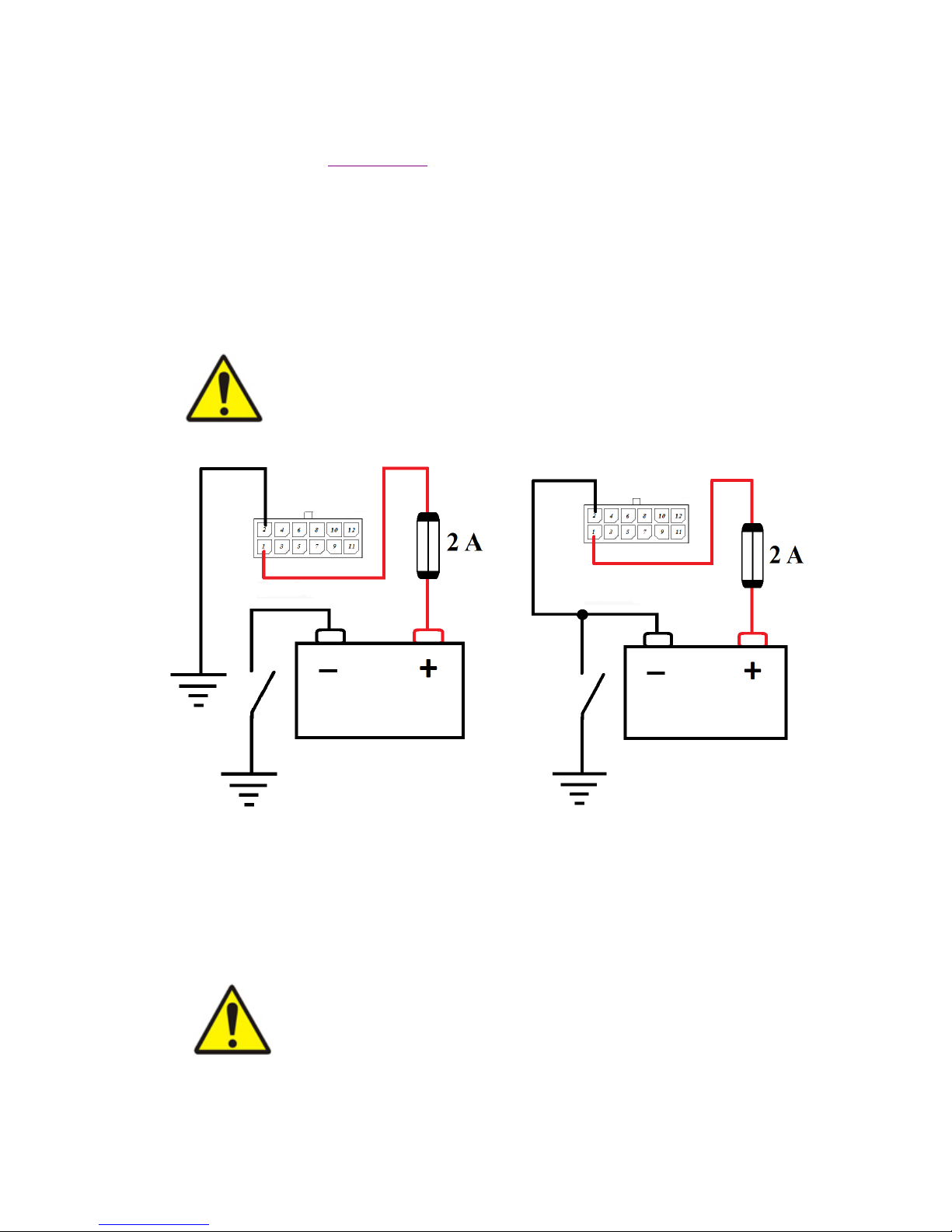
8.2. Power connection
Before connection the power to the tracker get sure that the mains voltage fits the acceptable
range (see the section “Specifications”)
Plug in the connector with the crimped wires to the X1 connector in the tracker, to connect the
GND contact to the wire of the main power, and PWR contact to the plus wire of the main
power. The wires’ cut must be 0.5 mm or more. All connections must provide dependable
contact and be safely isolated.
The preferable version is connection the tracker to the mains after the ground switcher.
Important!
Keep the power polarity!
It is necessary to set a 2 A fuse to the power circuit!
After the ground switch Before the ground switch
Pic.5.Connecting the main power to the X1 connector before and after the ground switch
schemes
Important!
When doing the electric welding on the automobile, or when the engine is
starting by the external current source the tracker must be disconnected from
automobile board mains! Otherwise the device can break down.

13
To prevent the intervention to device’s work and intentional damage it is recommended to seal
up the connectors, terminal blocks and the case of the tracker after its installation.
After the installation and connection the device is ready to work. If it was connected
appropriately, it starts the work automatically. The LED indication of the right working device
can be seen in the following section of this guide.

14
8.3. Connecting the analog sensors to tracker
Tracker has two analog inputs (AIN1 and AIN2) available in the interface connector X1. These
inputs can be used for measuring the direct current voltage in range 0..30 V.
Analog inputs can be used for measuring the vehicle parameters with value proportional to the
voltage level (ex. fuel level value from internal or external sensor)
Typical scheme of connecting the sensor to analog input can be seen on pic. 6.
To increase the accuracy of measurements it’s recommended to draw the minus wire directly
from the sensor, but it’s acceptable to use the common ground.
Pic.6.Installing analog sensors to AIN input
There are two ways of analyzing data from analog input, by the setting AIN or DIN channel with
corresponding number:
AIN channel shows the voltage on the corresponding input;
DIN channel indicates that the voltage on this input is higher, than the threshold, assigned
in TLD parameter for this channel (see pic. 7). If the voltage is higher, than this
threshold, the channel value is 1, if it’s lower – 0.

15
Pic.7.DIN channel setting in configurator
8.4. Connecting contact sensors (buttons)
To connect a contact sensor (button) to tracker use one of the following ways – closing to a
common ground or to a common plus (vehicle mains) (both cases use analog input, schemes
illustrate it on example of AIN1):
Pic.8. Connecting button to analog input closing to a common ground
16
Pic.9. Connecting button to analog input closing to common mains
To use this kind of sensors set up the DIN channel in configurator (with same number as used
input) (see pic.7).
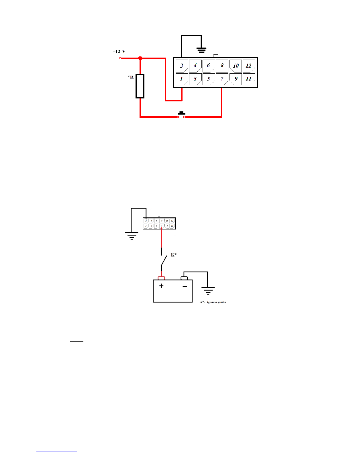
8.5. Ignition detecting
To detect the automobile ignition also use analog input, connected by the following schemes:
If there’s a plus-circuit splitter in the automobile, use the scheme from pic. 10 to detect
the ignition.
Pic.10.Ignition detecting in plus circuit
If there’s a minus-circuit splitter in automobile, use the scheme from pic. 11.
Note: external resistor 15 kΩ to 51 kΩ, capacity from 0.1 W.

17
Pic.11.Ignition detecting in minus circuit
To detect the automobile ignition it is recommended to use the DIN channel with parameter TLD
set to value 8 (see pic. 7). It is acceptable to use the AIN channel instead, but in this case the
threshold must be set in virtual ignition sensor in monitoring system.
8.6. Connecting the frequency/pulse inputs of tracker
Tracker has two frequency/pulse inputs (FRQ1, FRQ2)6. One of the working modes (frequency
or pulse) can be chosen for each of them.
Use one of the following schemes to connect an external device, depending on its type.
To connect the sensor with positive output to the tracker, plug in the connector with the crimped
wires the way to connect the GND contact to the ground, and the FRQ1 or FRQ2 to positive
output of external sensor.
Pic.12.Installing the sensor with frequency output to the tracker
6
These inputs were marked DIN1 and DIN2 on trackers manufactured earlier than September 2017.

18
To connect a device with “open collector” output it is necessary to add a resistor 2..10 KΩ
(depending on acceptable output amperage) by the pic.13 scheme:
Pic.13. Connecting the “open collector” output device
To connect a device with optocoupled output use the following scheme (pic.14). It is
recommended to add a resistor to a optron collector’s circuit (resistor’s parameters are the same
as in previous kind of conection).
Pic.14. Connecting device with optocoupled output
Get sure that the incoming voltage for these inputs fit the appropriate range:
2..30 V.

19
External sensors must be serviceable and provide dependable work. Otherwise,
manufacturer isn’t responsible for right sensor status registration (losing the
contact etc.).
To work with sensor data set up the corresponding channel in configurator (as seen in Channel
setting in configurator):
To count the pulses from sensor set the CNT channel;
To measure the frequence set the FRQ channel.

20
8.7. Connecting the power output of the tracker
Tracker has one power output (DOUT contact). It can be used for controlling the external
executive devices.
Important!
Maximum acceptable load voltage must not be higher than 30 V.
Maximal acceptable amperage - 1 А.
Typical load connection scheme (pic. 15):
Pic.15.Power output load connection (right side – internal scheme of power output)
For external device control use the channel REL1. When its value is set to 1 (in configurator (as
in pic. 16) or by remote command (SMS or TCP, see remote configuration guide on the
website)), the ground circuit of the controlled device (“load” on the pic. 15) connects with
ground circuit of a vehicle, providing the device work. When the value is 0, contact disconnects.
Pic.16. Setting the value to REL1 channel in configurator

21
8.8. Connecting devices to RS-485 interface
Tracker has an ability to read data from digital sensors by RS-485 interface (those that work by
LLS protocol). This interface allows connecting several sensors simultaneously. Typical scheme
of connecting devices to this interface is on pic. 17:
Pic.17.Connecting devices to RS-485 interface
Data from sensors connected by this interface is shown in channels LLS1..LLS12. To set the
correspondence between sensor and channel use the address parameter (ADDR). Also there is a
parameter to set working mode - MODE with these acceptable values:
FUEL – fuel level measuring mode,
TMP – temperature measuring mode,
RFID – reading RFID-marks.
Pic.18.LLS channel parameter

22
8.9 Connecting devices to 1-Wire interface
1-Wire allows to work with DS18B20 temperature sensors and iButton electronic identifiers.
There’s an ability to work with DS18B20 only in parasitic power mode. Connection is shown on
scheme:
Pic.19 Connecting temperature sensor to tracker 1-Wire input
It is possible to connect three sensors at the same time. Also, it’s possible to connect one iButton
device parallel to sensors.
Pic.20.Connecting several sensors to 1-Wire input
Data from sensors is shown in WIR1..WIR3 channels. iButton identifying number – IBT1.
There’s a parameter WIR_AUTOSEARCH, which allows searching for external sensors and
assigning channels to them automatically. Default value of this parameter is 1 (autosearch is
enabled). To disable it, change the value of parameter to 0 in configurator (“Settings” tab,
“Advanced” button).
In case of disabled autosearch, the manual setting of the channel is necessary. To set the channel
to the sensor, assign its ID to the corresponding parameter of the channel (as in pic.21)

23
Pic.21 Settings of WIR channel in configurator

24
9. Device status indication
There are two status LEDs on a tracker: SAT and DAT.
SAT indicator
SAT LED indicates the positioning status (GPS/GLONASS satellites).
When power is connected appropriately, LEDs light and go out twice in order from SAT to
DAT: it signals that work started successfully. Then SAT begins to blink once or twice in 5
seconds – it is a stable device work indication. If it blinks twice, the device is searching for
satellites; if it blinks once – satellites are captured.
DAT indicator
DAT indicator lights while sending data sets by GPRS and indicates the work with mobile net. If
it’s lighting permanently, the connection is not established yet, if it’s blinking – data is sending
successfully.
If both LEDs are blinking, or both LEDs light permanently, there’s a
system error of device. You should connect the service center.

25
10. Contacts
Phone: 8 (800) 700-42-73
E-mail: info@cguard.ru
Website: cguard.ru
Address: 432027, Russian Federation,
Ulyanovsk,
Yunosti str., 5а
Technical support:
E-mail: support@cguard.ru
Skype: cguard_support
 Loading...