

Page 1

CGAntenna
GW‐1000APRSTOTALSOLUTION
v1.2.1
UserManual
Lastmodified:12Jul2016
1
Page 2

Table of Contents
1. Introduction
2. Connectivity
3. Front indicators
4. Software installation
5. Basic configuration setting
6. Bluetooth TNC (Optional)
7. Reminds
2
Page 3

1. Introduction
GW-1000 has features of Digipeater, iGate, APRS data monitoring &
Weather station report. In the future, it could extend to Telemetry by
firmware upgrading.
It has Bluetooth capability.
1.1. Digipeater
GW-1000 supports APRS packet repeat which is called Digipeater. It
reads APRS data from RF transceiver, repacks it and send out via RF
transceiver
.
1.2. iGate
It supports RF-IS and IS-RF both way data relay.
RF-IS, The APRS data from RF will be relayed to APRS IS network. So
people can check these data on the internet. E.g arps.fi
IS-RF, the GW-1000 could read the APRS data which IS server sent to it
and relay to RF.
1.3. Weather station report
Currently 2 kinds of weather stations are supported.
1, Peetbros weather station in ‘Complete record mode’
2, CG Antenna WX-01 simple weather station. It could detect
temperature, humidity & air pressure. Possible to connect to 3
rd
party
anemometer & rain gauge.
1.4. TNC
GW-1000 has an embedded KISS TNC. The speed is 1200 baud rate. It
supports KISS control protocol. Using AFSK to modulate & de-modulate
the signal. With extra Bluetooth installed, it could be used as a standalone
APRS KISS TNC.
1.5 Bluetooth(Optional)
With the Bluetooth module installed, the Bluetooth indicator will blink. If
it is paired with Bluetooth terminal (such as computer, tablet or smart
3
Page 4

phone), the indicator will light on solid. The device name is SPP-CA. The
pairing passcode is 1234.
2. Connectivity
There are 4 connectors on the back panel.
Power supply
Radio connection port
Ethernet port
Data extension port
2.1. Power supply
GW-1000 supports 9-15VDC. Current drain <0.8A
2.2. Radio connection port
Pin 1. AF OUT, GW-1000 audio output to radio input
Pin 2. GND, ground
Pin 3. PTT, radio PTT
Pin 5. AF IN, GW-1000 audio input from radio output
For normal Kenwood and generic handheld radio which has a 3.5mm &
2.5mm microphone and speaker plug. The 3.5mm jack as microphone
and the 2.5mm jack as speaker.
Wiring as
4
Page 5
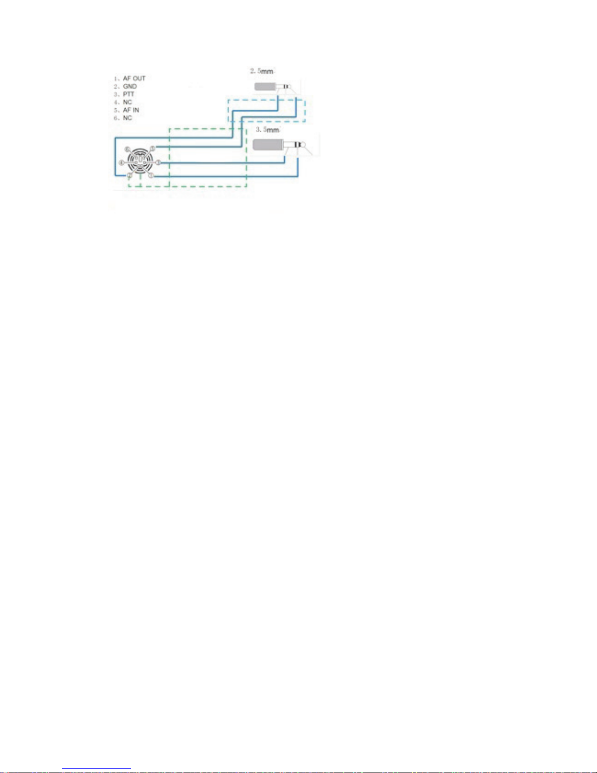
Mini din 6, pin 1 to the ring of 3.5mm jack(AF out)
Mini din 6, pin 3 to the sleeve of 3.5mm jack(PTT)
Mini din 6, pin 5 to the tip of 2.5mm jack(AF in)
Mini din 6, pin 2 to the sleeve of 2.5mm jack(GND)
For most of Yaesu, ICOM & Kenwood mobile radios which are using
same mini din 6 data jack. Just one to one by straight connect 4 wires. Pin
1, pin 2, pin 3, pin 5.
For Yaesu handheld radio, there is no PTT wire. So user must open the
GW-1000, locate the JP3 2-pin jumper which is beside the mini-din 6
socket. Put a jumper cap on it. Then GW-1000 could properly drive
Yaesu handheld radio to transmit.
2.3. Ethernet port
802.11 Ethernet port for connecting to Internet
2.4. Data extension port
DB-9 data port for connecting weather station, LCD & external
Telemetry data board(in future)
2.4.1. DB-9 port definition
5
Page 6

pin-1 +5VDC
pin-2 GND
pin-3 LCD 1
pin-4 LCD 2
pin-5 PeetBros weather station
pin-6 WX-01 simple weather data board
2.4.2. For Peetbros Ultimeter connection
Connect pin 2 to the ground of PB data connector
Connect pin 5 to the data output of PB data connector
2.4.3. For WX-01 simple weather station connection
Connect pin 1 to the +5V of WX-01
Connect pin 2 to the ground of WX-01
Connect pin 6 to the data output of WX-01
Due to voltage decrease, please connect external +5VDC to the WX-01 if
it is put more than 3 meters away from GW-1000.
2.4.4. For LCD connection
Refer to the wiring diagram at the back of GW-1000 LCD. The LCD is
supplied separately.
6
Page 7

3. Front indicators
There are 6 indicators at the front edge of the GW-1000.
Power, Internet, APRS receive, Decode/Encode, APRS transmit,
Bluetooth
3.1. Power
This indicator is on when DC power is supplied.
3.2. Internet
This indicator is flash when GW-1000 trying to connect to APRS IS
server. After connection is established, it goes to solid.
3.3. APRS receive
This indicator is on when GW-1000 is receiving APRS packet.
3.4. Decode/Encode
This indicator is on when GW-1000 is decoding or encoding APRS
packet data.
3.5. APRS transmit
This indicator is on When GW-1000 is transmitting the APRS packet.
3.6. Bluetooth
Only working if the optional Bluetooth module is installed.
Flash – pairing with other Bluetooth terminal. Such as smartphone, table
or computer.
Solid – paired with other side.
7
Page 8

4. Software installation
The configuration software support WinXP, Win 2000, Win 7, Win 8.
Minimal operation system requirement:
win xp (service pack 3)
Microsoft .Net Framework client profile 4.
Client configuration software download link.
http://www.cgantenna.be/driver/GW1000v102.zip
Download this file and unzip it to your harddisk.
Step 1. Create a folder on your hard drive. E.g ‘c:\gw1000’
Step 2. Copy all files into this folder.
Step 3. Click ‘DOTNET40CLIENT.EXE’. It will install Microsoft .Net
Framework client profile 4. If you have already installed this or higher
version, you could ignore this step.
Now you can run the configuration software on your PC. Click ‘APRS
GW-1000 Configure.exe’ in the ‘C:\GW1000’
8
Page 9

5. Basic configuration setting
At the top section of configuration software, user must input the IP
address and passcode of the GW-1000 which would be connected. The
default IP address is 192.168.1.120 and passcode is 00000000.
5.1. Status tab
It shows the unit information. Such as firmware version, on board
voltage. Network information. Weather station data.
5.2. General tab
GW-1000 IP
Default IP address is 192.168.1.120, netmask 255.255.255.0
In case, you forget the IP address or the configuration setting corrupted,
you could choose to go back default setting by open the GW-1000 case
(Please disconnect the power first). Locate the RESET button. Push and
hold the button. Meanwhile connect the power. You will see all the lights
flash. Then release the button. System does a hard reset. It will set GW1000 to default IP address 192.168.1.120, netmask 255.255.255.0.
Router- the IP address of your router.
Callsign – The radio callsign.
SSID - This is the SSID for your iGate. Usually it is 10.
Passcode – The passcode for APRS IS login.
Filter – The APRS server side filter.
APRS server IP
You could manually setup 3 different APRS server IP address
Polling – GW-1000 will try each server if one is not available
Always use Server A - Only connect to the 1
st
server.
9
Page 10

Restart after connection overtime twice – GW-1000 will restart if it
fails to connect to server twice
TX Delay- This value is the delay time in milliseconds before sending
APRS packet. It is necessary for transmit to stabilize the TX frequency,
also for receiver to synchronize the session.
TX Skip – This value is the skip time in milliseconds between two APRS
packets.
LCD- The general switch for the LCD display(optional).
10
Page 11

5.3. Beacon tab
Active the beacon to automatically report the position of the iGate or
Digipeater. Either by radio RF or APRS IS.
SSID – SSID for beacon. We suggest that use 0 to 4. It will be used as
Digipeater SSID if it is enabled.
IS Report- APRS internet service transmitting interval in seconds. 0
means no transmitting.
RF Report- Radio RF transmitting interval in seconds. 0 means no
transmitting.
PATH – APRS path name. GW-1000 supports only WIDE1, WIDE2 and
max. to 2 hops.
Latitude – Latitude of the station. Format in datum WGS1984. E.g. 54
deg. 17.10 min N.
Longitude – Longitude of the station. Format in datum WGS1984. E.g.
120 deg. 23.20 min E
Comment - The text in comment position of the APRS beacon packet.
11
Page 12

5.4. Weather station tab
For Peetbros weather station, you must set up the weather station in
‘Complete record Mode’, speed rate 2400 bps.
SSID – SSID for weather station. Suggest using 13.
IS Report- APRS internet service transmitting interval in seconds. 0
means no transmitting.
RF Report- Radio RF transmitting interval in seconds. 0 means no
transmitting.
PATH– APRS path name. GW-1000 supports only WIDE1, WIDE2 and
max. to 2 hops.
Latitude – Latitude of the station. Format in datum WGS1984. E.g. 54
deg. 17.10 min N.
Longitude – Longitude of the station. Format in datum WGS1984. E.g.
120 deg. 23.20 min E
Comment - The text in comment position of the APRS weather report
packet.
12
Page 13

5.5. Digipeater tab
Relay on WIDE1- Enable Digipeater on any APRS packet with WIDE1
path.
Relay on WIDE2- Enable Digipeater on any APRS packet with WIDE2
path.
Insert Gateway Name- Insert gateway name in the new forward APRS
packet.
TX if channel free- Transmit the APRS packet when the channel is
quiet.
TX wait- This value is the Digipeater waiting time in milliseconds before
forwarding the packet.
LCD Display – Display DigiPeater data on LCD.
13
Page 14

5.6. iGate tab
RF-IS – Enable RF to IS. GW-1000 will upload the APRS data to APRS
internet service once it receives the APRS packets from RF.
IS-RF – Enable IS to RF. GW-1000 will download the APRS data from
APRS internet service and transmit out by radio RF.
* Be careful to switch on IS-RF, it will make your iGate very busy due to
much data coming from IS.
5.7. Monitor tab
Show all traffic information.
14
Page 15

15
6. Bluetooth Extension (Optional)
With Bluetooth wireless extension, you could connect your smartphone,
tablet or computer to GW-1000. Then you could do following tasks
1. GW-1000 could output the received station information in NMEA
or KISS format
2. GW-1000 could be used as a 1200 bps packet TNC modem
If user installed the Bluetooth kit on the GW-1000, it could be turned into
a Bluetooth TNC. The default Bluetooth device name is SPP-CA and the
pairing code is 1234.
There are various software support Bluetooth TNC. These software could
be run on computer, smartphone or tablet. Choose the right suitable
software and do the next 2 steps to use the GW-1000 as Bluetooth TNC
Step 1. Bluetooth pairing your device with GW-1000
On your operating device, run the Bluetooth management software,
search for the device named “SPP-CA”. Pair it with code 1234.
Step 2. In your APRS or TNC software, normally there is an option for
TNC. So choose the Bluetooth device that is just paired.
Recommended software:
1. APRSdroid
It runs on Android system. APRSdroid could use GW-1000 as
Bluetooth TNC.
2. Locus Map
Running on Android system. Locus Map directly support
OpenstreetMap and several other popular free or open source map.
In its Setting -> GPS and location -> Bluetooth GPS, there is
NMEA READER function. It could read NMEA output data from
GW-1000. Then point the station position on the map.
 Loading...