

Page 1
the
Great Outdoors
Assembly and
Owner’s Manual
®
A053041
X-Series
Portable
Gas Grill
L.P. Gas
Cylinder
Not Included
ASSEMBLER / INSTALLER:
Leave these instructions with the consumer.
CONSUMER / USER:
Read all of these instructions and keep them in a safe place for future reference.
FOR YOUR SAFETY
If you smell gas:
1
Shut off gas to the appliance.
2
Extinguish any open flame.
3
Open lid.
4
If odor continues, immediately call
your gas supplier or fire department.
FOR YOUR SAFETY
1
Do not store or use gasoline or other
flammable vapors and liquids in the
vicinity of this or any other appliance.
2
An unconnected liquid propane
cylinder should not be stored in the
vicinity of this or any other appliance.
FOR YOUR SAFETY: Never leave a grill unattended when in use.
Page 2

Table of Contents
Page Number
Chapter 1 - INSTALLATION
Necessary Information . . . . . . . . . . . . . . . . . . . . . . . . . . .
Choosing a Safe Location . . . . . . . . . . . . . . . . . . . . . . . . .
Portable L.P. Gas Grills . . . . . . . . . . . . . . . . . . . . . . . . . . .
L.P. Gas Dealer Instructions . . . . . . . . . . . . . . . . . . . . . . .
Chapter 2 - ASSEMBLY INSTRUCTIONS
Step 1 ( Identifying Parts ) . . . . . . . . . . . . . . . . . . . . . . . . .
Step 2 ( Attach Legs ) . . . . . . . . . . . . . . . . . . . . . . . . . . . .
Step 3 ( Attach Feet ) . . . . . . . . . . . . . . . . . . . . . . . . . . . .
Step 4 ( Tank Retainer ) . . . . . . . . . . . . . . . . . . . . . . . . . .
Step 5 ( Modesty Panel ) . . . . . . . . . . . . . . . . . . . . . . . . . .
Step 6 ( Side Tables ) . . . . . . . . . . . . . . . . . . . . . . . . . . . .
Step 7 ( Grill Head ) . . . . . . . . . . . . . . . . . . . . . . . . . . . . . .
Step 8 ( Ignitor Wire ) . . . . . . . . . . . . . . . . . . . . . . . . . . . .
Step 9 ( Lid Handle ) . . . . . . . . . . . . . . . . . . . . . . . . . . . . .
Step 10 ( Internal Parts ) . . . . . . . . . . . . . . . . . . . . . . . . . .
Step 11 ( Warming Rack ) . . . . . . . . . . . . . . . . . . . . . . . . .
Step 12 ( Drip Cup ) . . . . . . . . . . . . . . . . . . . . . . . . . . . . . .
Installing an L.P. Gas Cylinder . . . . . . . . . . . . . . . . . . . . .
4
4
4
5-7
8
9
10
11
12
13
14
15
16
17
18
19
20
21
22-23
Formerly:
®
Now:
CFM Corporation
2695 Meadowvale Boulevard
Mississauga, Ontario L5N 8A3 Canada
(800) 668-5323
www.cfmcorp.com
Service Note: If you are experiencing difficulties or are dissatisfied with your purchase, please contact CFM at
the telephone number listed above prior to returning your grill to the store.
Page 3
X-Frame Model Series Gas Grill
Installation 1Chapter
Necessary Information to
Safely Use a Gas Grill
The gas fuel used by this product is
highly flammable and must be used in
a responsible and cautious manner.
It is your responsibility to assemble,
operate, and maintain your gas
barbecue grill properly.
·
Operating this or any gas-fired appliance
in an enclosed area can produce a build-up
of carbon-monoxide, which could result in
injury or death.
2. Installation must conform with local
codes
either the National Fuel Gas Code, ANSI
Z223.1, NFPA 54 (USA), or CAN/CGA-B
149.2, Propane Installation Code (Canada)
and CAN/CGA-B 149.1 Natural Gas
Installation Code.
To check local codes, contact your local gas
dealer or gas company listed in the Yellow
Pages for recommended installation
procedures and regulations.
3. This appliance is not intended to be
installed in or on a recreational vehicle
and/or boat.
or, in the absence of local codes, with
If these instructions are ignored, there
is a possibility of a hazardous fire or
explosion which could result in proper-
ty damage, physical injury or death.
Choosing a Safe Location
for a Gas Barbecue Grill
1. The gas barbecue grill may only be used
for cooking out-of-doors.
· Do not operate this barbecue in garages,
breeze ways, sheds or any enclosed area.
4. Keep the barbecue grill at least 24
inches (61 cm) away from any combustible
construction.
·
Do not use a grill under a ceiling or cover
where the heat or flame could cause
damage.
·
Choose a level surface where the grill is
not facing directly into the wind.
·
Avoid moving the grill during use.
5. The grill area must be clear and free from
combustible materials, gasoline, and any
other flammable liquids or vapors.
·
Do not use lighter fluid or charcoal
briquettes in a gas grill. The flow of
combustion and ventilation air is not to be
obstructed. The ventilation openings of the
cylinder enclosure must be kept free and
clear from other debris. Do not store grill
covers or other items in the cylinder area.
4
Page 4
The L.P. Fuel Supply System
9. Make sure that the drip pan is in place
under the grill bottom.
Hot drippings from cooking food could
·
damage the fuel supply system.
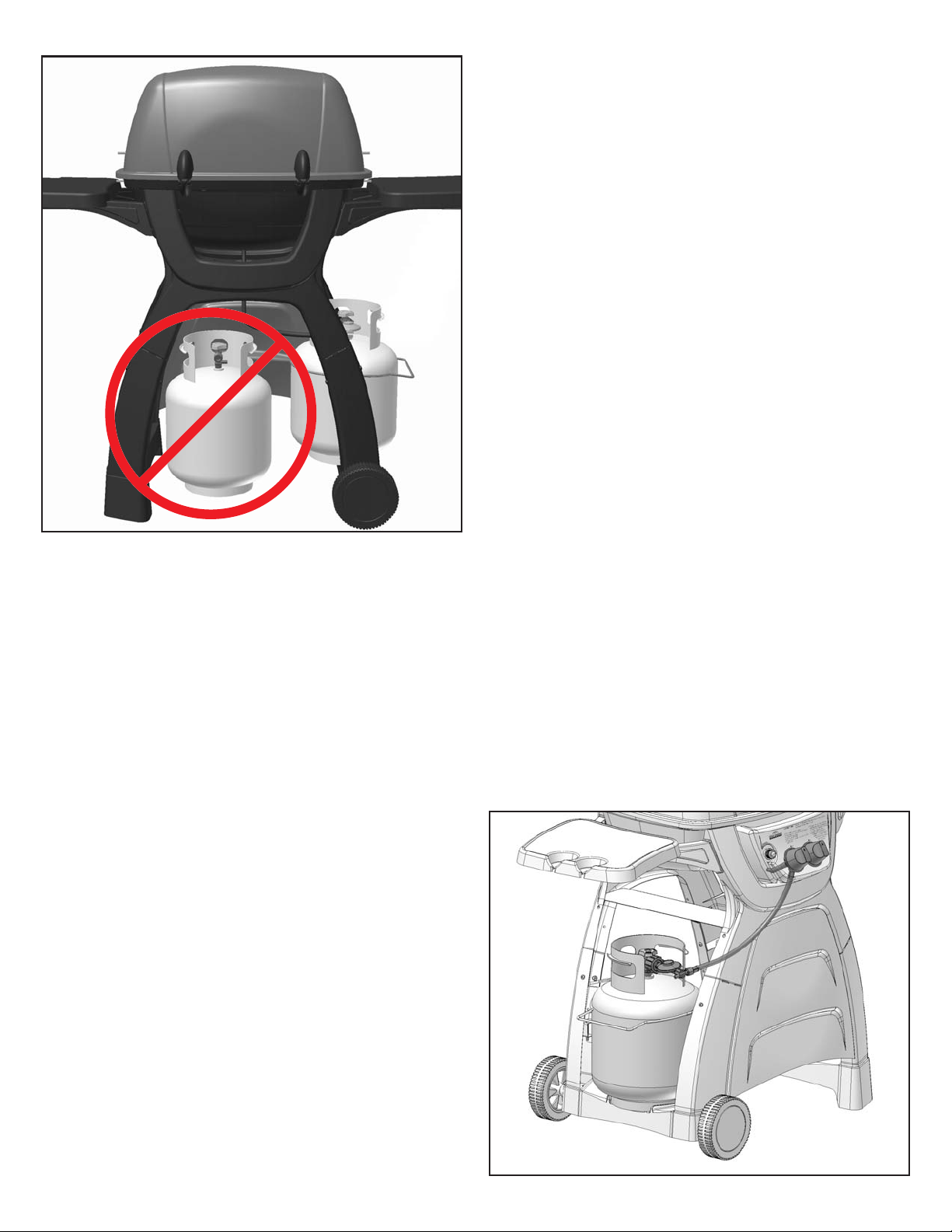
6. Do Not store a spare L.P. gas cylinder
under or near this appliance.
Do not store an L.P. cylinder in a building,
garage or any other enclosed area. Instead,
store the cylinder outdoors in a well
ventilated area, away from people and out of
the reach of children.
7. NOT FOR USE BY CHILDREN.
Place your barbecue grill in a location
·
away from children and pets.
Do not leave grill unattended when in use.
·
IMPORTANT:
unattended when in use.
NEVER leave a grill
Portable L.P. Gas
Barbecue Grills
WARNING:
appliance designed for L.P. gas. Use only
liquid propane (L.P.) gas in an appliance
designed for L.P. gas.
L.P. Gas
Liquid Propane (abbreviated L.P.) gas is
stored under high pressure inside a cylinder
and will vaporize when released. It is
important that there are no leaky connections
on the grill fuel supply system. Refer to the
Leak Testing section of this manual.
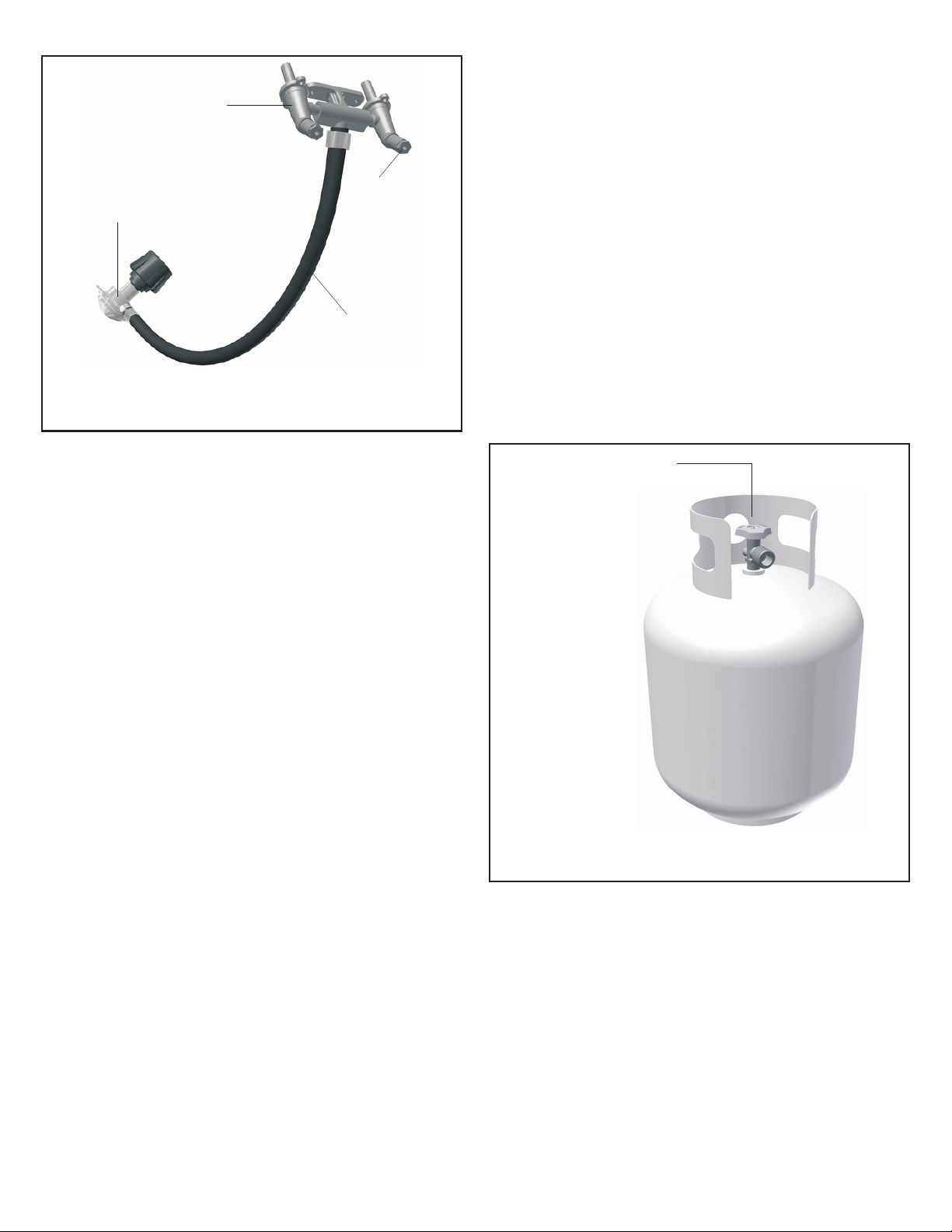
The L.P. Fuel Supply System
An L.P. gas grill requires a fuel delivery
system made up of a L.P. gas supply
cylinder, a fuel regulator with hose and a
gas-control valve.
Do not use natural gas in an
8. The outside of the barbecue grill will
become hot during use.
To avoid burns, do not touch any hot grill
·
surface. If necessary, use a protective glove
when operating control knobs, tank shut-off
valve, or lid handle.
Do not place combustible material, such
·
as cloth or plastic, on grill surface during
use.
·
Do not lean on side tables or place more
than 15 pounds of weight on a side table.
The L.P. Fuel Supply System
5
Page 5
Dual Burner
Fuel-Control Valve
4. The pressure regulator and hose
assembly provided is factory set at an outlet
pressure of 11 inches water column (.4 lb.
per sq. Inch).
Type 1 Fuel
Regulator
Fuel Supply
Valve
Orifice
Hose
The L.P. Fuel Supply System
(the fuel regulator and hose)
FUEL REGULATOR AND HOSE
The fuel regulator supplied is equipped with
a Type 1 coupling nut. Do not attempt to
connect to any other L.P. cylinder not
equipped with a mating Type 1 cylinder
valve. This grill is not to be used with any
other cylinder connection device.
The fuel regulator and hose assembly with
the Type 1 fitting supplied must be used with
the appliance. Do not use a hose and
regulator assembly other than the one
supplied with the grill or a manufacturer’s
replacement fuel pressure regulator
assembly.
The Type 1 connection system has the
following features:
1. The system will not allow gas to flow until
a positive connection has been made.
2. The system has a thermal element that
will shut off the flow of gas between 240°F
and 300°F.
3. The system has a flow-limiting device
which, when activated, will limit the flow of
gas to 10 cubic feet per hour.
WARNING:
Any attempt to adjust the
regulator is dangerous and could create a
situation causing personal injury or property
damage. Consult your L.P. gas dealer if you
think the regulator is not working properly.
L.P. GAS SUPPLY CYLINDER
L.P. Cylinders can be obtained at the store
where you purchased your grill or from an
authorized L.P. gas dealer.
Cylinder Control
Valve
L.P. Gas
Cylinder
NOTE:
L.P. Gas
Cylinder
NOT
INCLUDED
The L.P. Fuel Supply System
(L.P. gas cylinder)
L.P. GAS CYLINDER SPECIFICATIONS
Any L.P. gas-supply cylinder used with this
grill must be approximately 12 inches
diameter and 18 inches high.
The maximum
fuel capacity must be 20 pounds of propane.
Full-cylinder weight should be approximately
38 pounds (43.7 lbs. Nominal water
capacity).
6
Page 6

The L.P. gas cylinder must have a shut-off
valve
cylinder-valve outlet.
terminating in a Type 1 L.P. gas-
A Type 1 compatible
cylinder with a Type 1 cylinder valve has a
positive seating connection that does not
permit gas flow until a positive seal has been
obtained.
The cylinder must be arranged for vapor
withdrawal. It must also include a collar to
protect the cylinder valve. A safety-relief
device having direct communication with the
vapor space of cylinder must be provided.
This will expel high-pressure gas if the
cylinder is overfilled or overheated.
Have the gas dealer weigh the cylinder
after filling to ensure that the cylinder is not
overfilled.
DANGER:
a.) Do not store a spare L.P. gas cylinder
under or near this appliance.
b.) Never fill the gas cylinder beyond 80
percent full.
c.) If the information in (a.) and (b.) Is not
followed exactly, a fire causing serious
injury or death may occur.
All L.P. gas cylinders used with this
appliance shall be constructed and marked
in accordance with the specifications for L.P.
gas cylinders of the U.S. Department of
Transportation (DOT) or the National
Standard of Canada, CAN/CSA-B339,
Cylinders, Spheres and Tubes for
Transportation of Dangerous Goods; and
Commission, as applicable; and shall be
provided with a listed overfilling-prevention
device. Read labels on the L.P. gas-supply
cylinder.
DANGER:
Do not insert any foreign objects
into the valve outlet. You may damage the
back check, A damaged back check can
cause a leak, which could result in explosion,
fire, severe personal injury or death.
Allow only a qualified L.P. gas dealer to
fill or repair an L.P. gas-supply cylinder.
Inform the gas dealer if it is a new or used
cylinder to be filled. Caution the gas dealer
not to overfill the fuel cylinder.
TRANSPORTING A FULL CYLINDER
WARNING:
Handle a full cylinder with care.
Gas is under high pressure.
You should transport only one cylinder at a
time. Transport the cylinder in an upright and
secure manner with the control valve turned
off and the POL dust cap in place.
Do not transport a cylinder in the passenger
compartment of a vehicle.
Do not leave cylinder in direct sunlight or in
a high-heat area such as a closed car trunk.
High-heat areas could cause the relief valve
to vent gas.
Use a cylinder cap on the cylinder-valve
outlet during transport and when the cylinder
is not connected to the grill. Keep cylinder
valve closed when not in use.
After filling, have the gas dealer check for
leaks and that the relief valve remains free to
function.
7
Page 7
Take These Instructions to the L.P. Gas Dealer
When using a cylinder exchange, be sure the
exchanged cylinder is a Type 1 cylinder; a 510
POL cylinder will not fit a Type 1 regulator.
FILLING AND PURGING
TYPE 1 L.P. GAS CYLINDERS
DANGER:
cylinders must be performed by personnel who
have been thoroughly trained in accepted L.P.
gas industry procedures. Failure to follow this
instruction may result in explosion, fire, severe
personal injury or death.
IMPORTANT:
filling. This tank is easily filled with a standard
CGA 510 POL filling connection.
Purging and filling of L.P. gas
Purge new cylinders before
The L.P. gas cylinder has a Type 1 cylinder
valve with a back-check module in its outlet
that will not permit gas to flow until an
evacuation device is installed. To purge the
L.P. gas cylinder, the back-check module must
be opened with an evacuation device.
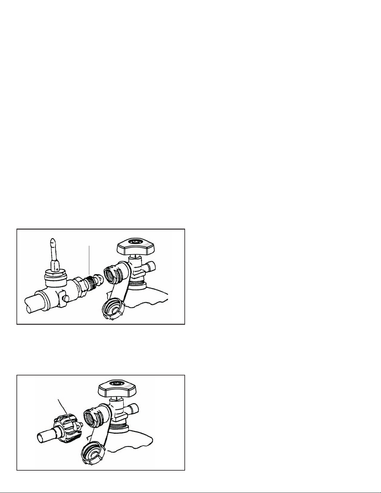
PURGING AND EVACUATION DEVICES
FOR L.P. GAS CYLINDER WITH TYPE 1
CYLINDER VALVES
A. Hose-end valve with a bleed port: Purging
can be accomplished using a hose-end valve
containing a bleed port, which also allows for
evacuation without the use of an adapter.
B. Hose-end valve without a bleed port:
When a hose-end valve does not have a bleed
port, a separate device must be used for
evacuation.
CGA-510 POL
Example A
Filling a Type 1 Cylinder Valve
Example A: shows a CGA-510 POL fitting.
Example B: shows using a Type 1 POL fitting.
Type 1
(cut away to see fitting)
C. Purging using a Type 1 connection: L.P.
gas cylinder evacuation can be accomplished
during each purging by using a Type 1
connection. The Type 1 valve outlet has 15/16” external ACME right-hand thread that will
accept this connection.
CAUTION:
cylinder, do not insert a POL plug into the
valve outlet. Insertion of this plug will prevent
the back-check from closing. Use ONLY the
provided cap and strap attached to the outlet.
Close the cylinder valve knob before returning
the cylinder to the customer.
For proper purging procedures in the USA,
refer to: Safety Bulletin NPGA # 133, “Purging
L.P. Gas Cylinders,” and Safety Bulletin NPGA
#130, “Recommended Procedures for Filling
Cylinders.”
After purging or filling an L.P. gas
Example B
DANGER:
beyond 80% full. If this information is not
followed exactly, a fire causing serious injury
or death may occur.
8
Do not fill an L.P. gas cylinder
Page 8
X-Frame Model Series Gas Grill
Assembly Instructions 2Chapter
Getting Started
1. Please follow the steps in the order that
they are presented.
2. Assemble the grill where you plan to use
it.
3. You may want to place an old towel or
cloth at the assembly site to prevent nuts
and bolts from becoming lost.
4. Have a friend help. An assistant can
make the assembly easier by holding the
parts in place while you fasten the nuts and
bolts.
5. To be ready to barbecue immediately,
have the L.P. gas cylinder filled by an
authorized L.P. dealer or cylinder exchange
center.
Unpacking the Grill Parts
1. Remove and set aside all inner boxes
and parts from the master carton.
2. Remove and set aside all wrapping
paper and additional packaging from the
parts.
3. Do not destroy carton or packing until
your grill is completely assembled and
operating to your satisfaction.
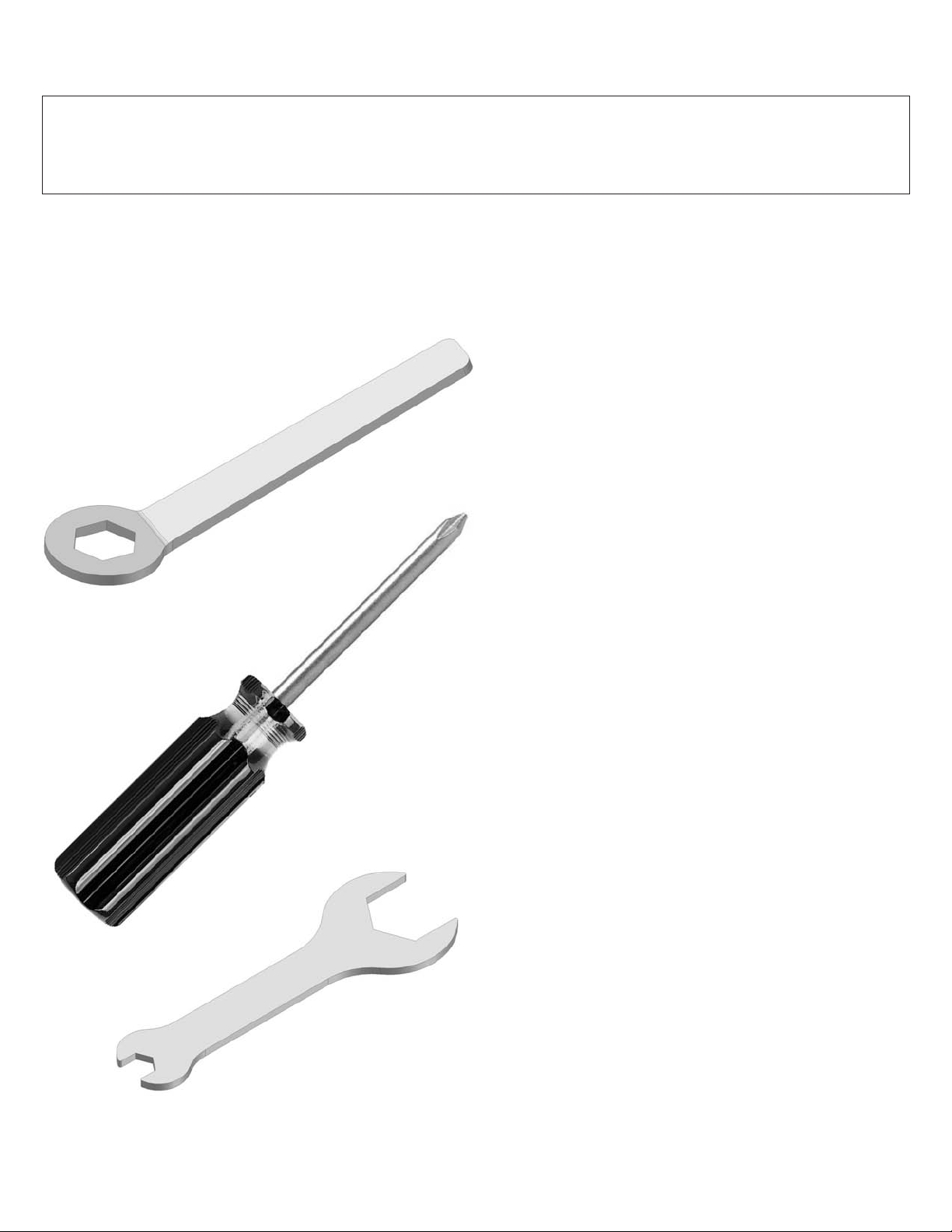
Tools needed to assemble grill:
(tools included)
·
10mm closed-end wrench*
·
Phillips-head screwdriver
·
17mm / 7mm open-end wrench*
A socket set or an adjustable wrench may be used
*
in place of the open-end wrenches if desired.
9
Page 9
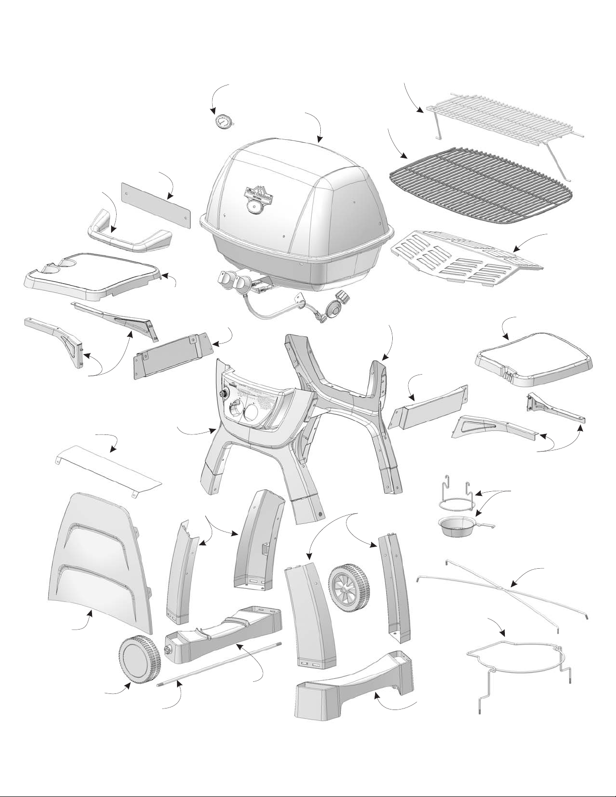
Assembly Step 1 - Identifying the Grill Parts
Locate these parts:
Note: Refer to the parts
listing on page 33 of the
manual for replacement part
information.
Handle
Heat Shield
Lid Handle
Left Side
Table
Table
Bracket
Heat
Indicator
Grill Head
Assembly
Warming Rack
Cooking Grid
Rear
X-Frame
Heat
Plate
Right Side
Table
Table Arms
Tank
Heat Shield
Modesty
Panel
Front X-Frame
with Control Panel
Legs
Table
Bracket
Table Arms
Drip Cup
and Holder
Legs
Wire
X-Brace
Wire Tank
Retainer
Wheel
Axle
Not Pictured:
Master Hardware Pack
Left Foot
(Tank Holder)
Right Foot
10
Page 10

Assembly Step 2 - Attach Legs to X-Frames
Tools Needed:
LOCATE THESE PARTS:
Phillips head screwdriver
USE HARDWARE ”A”
M6x15mm
A
Bolt (8)
Attach the leg to the X-frame by
1.
M6 Flat
B
Washer (8)
inserting the top tabs into the
corresponding slots in the X-frame
as shown.
2.
Line up the bolt holes on the side of
each leg and insert a bolt into each
of the bolt holes.
X-Frame
with
Control
Panel
2 Left
Legs
X-Frame
2 Right
Legs
3.
Tighten the bolts securely.
4.
Repeat steps 1 through 3 above for
each leg and frame. Be sure to
match the correct leg component to
its corresponding side, left/right.
When these steps are complete, you
will have 2 sets of frames with legs
attached.
B
A
11
Page 11

Tools Needed:
Assembly Step 3 - Attach the Feet
LOCATE THESE PARTS:
Phillips head screwdriver
17mm Wrench
USE HARDWARE ”B”
A
Wheel
Washer(2)
Assemble the wheels and axle to the
1.
B
M10 Axle
Nut (2)
C
M6x15mm
Bolt (8)
tank-side foot as shown above right.
Insert the axle through the foot, one
wheel on each end, tighten one nut
and wheel washer on each end, and
snap the hub caps onto the wheels
D
M6 Flat
Washer (8)
B
Axle
Nut
Hub
Cap
A
Wheel
Washer
Left Foot
(tank side)
Wheel
Axle
Right Foot
2.
Attach each foot to the bottom of
the frame assemblies as shown.
The legs will snap into the feet.
Be sure the is on
the of the assembly as
left side
wheeled foot
shown.
3.
For each mounting location,
insert 2 bolts with washers as
shown.
4.
Once all of the bolts are
securely tightened,
position the assembly so
that the wheels are on
your left side as you
face it. (This is the front)
C
D
LEFT
FOOT
12
Page 12

Assembly Step 4 - Install the Tank Retainer
USE HARDWARE ”C”
M4 Wing
A
Nut (1)
Insert the legs of the wire tank retainer
1.
M4x10mm
B
Bolt (1)
M6 Wing
C
Nut (6)
into the mounting brackets inside the grill
legs. The wire tank retainer must be
mounted on the wheel side of the grill.
2.
Align the center hole of the x-brace wires,
insert the M4 bolt through both wires, and
thread on the M4 wing nut as
shown above right.
Tools Needed:
Phillips head screwdriver
LOCATE THESE PARTS:
Wire Tank
Retainer
B
A
Wire
X-Brace
3.
Insert the ends of the wire x-brace
into the mounting
holes located
near the
middle of
the grill legs
and thread
a M6 wing
nut onto
each end.
4.
Thread M6
wing nuts onto
the ends of the
wire tank retainer.
C
C
13
Page 13

Assembly Step 5 - Attach the Modesty Panel
Tools Needed:
LOCATE THESE PARTS:
Phillips head screwdriver
7mm Wrench
USE HARDWARE ”D”
B
M4 KEPS
A
Nut (6)
1.
Position the modesty panel between the front legs of the
M4x15mm
Bolt (6)
assembly. Align the mounting tabs with the bolt holes in
the legs.
From the back side of the assembly, insert the
2.
M4 bolts through each of the mounting holes
and thread on the M4 KEPS nuts.
insert the bolt indicated - it will be installed
yet
DO NOT
during a later assembly step.
IMPORTANT! The Tank Heat Shield
must be properly installed to provide an
additional precautionary safeguard.
Tank
Heat
Shield
Modesty
Panel
A
B
3.
Position the Tank Heat Shield
between the front and rear
x-frame assemblies as shown
below.
B
A
4.5.For each mounting hole, insert M4 bolts and
thread on M4 KEPS nuts.
Securely tighten all the bolts. Remember to set
aside the remaining bolt and nut for a later step.
14
Page 14

Assembly Step 6 - Attach the Side Tables
Tools Needed:
Phillips head
screwdriver
USE HARDWARE ”E”
10mm Wrench
LOCATE THESE PARTS:
Left Side Table
Table Mounting
Brackets (2)
A
M6x25mm
Bolt (8)
1.
To assemble each table, use one left and one right
B
M6 Hex
Nut (8)
C
Lock
Washer (8)
D
Washer
(8)
table arm.
2.
Line up the bolt hole of the table arms
to the INSIDE set of holes on the side
table as shown.
3.
For each bolt location, insert a M6 bolt.
Once all bolts are mounted, securely tighten.
4.
Align the assembled side table, along with one
side table bracket to the side of the grill
assembly as shown. Insert the pre-mounted
bolts through the mounting bracket and onto
the side of the
grill assembly.
Side Table Arms (2 Left, 2 Right)
Right Side Table
A
B
C
D
5.
For each bolt, thread on a flat washer,
lock washer and M6 hex nut.
Do not yet tighten the nuts.
6.
After 4 nuts are in place, securely
tighten all of the bolts.
7.
Repeat steps for the other side table.
15
Page 15

Assembly Step 7 - Installing the Grill Head
Tools Needed:
USE HARDWARE ”F”
Phillips head screwdriver
LOCATE THESE PARTS:
Grill Head
Assembly
M6x15mm
A
Bolt (4)
1.
Holding the grill head upright, slightly rotate
M6 Flat
B
Washer (4)
Bolt
C
Gasket (4)
the knob side down and set it onto the frame
assembly. The knobs will insert through the
control panel first, then rotate the grill head
down until it rests properly onto the frame.
2.
Line up the 4 bolt holes near the
inside corners of the grill tub.
(The lid will need to be opened
to access the bolt locations.)
3.
Loosely insert all of the bolts with
washers and gaskets.
4.
After all bolts are threaded, make sure the
control knobs centered and securely tighten
the bolts.
C
B
A
16
Page 16

Assembly Step 8 - Ignitor Installation
1. Locate the loose end of the
ignitor wire. Connect it to the
ignitor electrode underneath the
grill tub, between the two burner
tubes.
Installing the Battery
1.
Unscrew the cap from the ignitor button.
2.
Insert an AA battery (from the hardware pack)
The positive end of the battery faces out.
2.
Using the remaining bolt and nut from
Step 5 (page 14), bolt the hose bracket
to the frame.
Be sure the bolt mounts through the
modesty panel tabs and the frame leg.
Securely tighten the bolt and nut using
a phillips head screwdriver and 7mm
wrench.
Place the button spring and cap back onto
3.
the ignitor and thread it back on.
Test the ignitor: Make sure gas is off or
disconnected. Press the ignitor button and
check for a spark in the grill tub and the side
burner.
17
Page 17

Assembly Step 9 - Installing the Lid Handle
USE HARDWARE ”G”
M6 Wing
A B C
Nut (2)
M6 Flat
Washer (2)
No tools are required for this step.
LOCATE THESE PARTS:
Handle
Heat Shield
Bolt
Gasket (2)
Lid Handle
1. Align the lid handle bolts with the
mounting holes in the lid and set
the handle on the grill lid.
From the inside of the
2.
lid, thread on a gasket
onto each bolt.
3.
C
Place the Heat Shield
onto the bolts.
4.
B
Thread on a washer
and wing nut for each
A
handle bolt.
5.
Securely tighten the
wing nuts.
18
Page 18

Assembly Step 10 - Installing the Grids
LOCATE THESE PARTS:
Heat PlateCooking Grid
No tools are required
for this step.
2
2
1
1.2.Set the Heat Plate into the tub as
shown. It will rest on the lowest ledge
inside the tub, just above the burner.
Set the cooking grid into the tub. It will
rest on the topmost ledge of the tub.
19
Page 19

Assembly Step 11 - Install the Warming Rack
LOCATE THESE PARTS:
Warming Rack
Assembly
3.4.Work the other end of the rack into the
other side of the lid.
Insert the other foot of the warming
rack into the other side of the grill tub.
It will require slight bending to place
the foot into the mounting hole.
No tools are required for this step.
1.2.Position the warming rack as shown and
insert one end of the rack into the lid as
shown.
Working on the same side of the grill,
insert one foot of the warming rack into
the mounting hole near the top of the grill
tub.
1
3
2
4
20
Page 20

Assembly Step 12 - Install the Drip Cup
LOCATE THESE PARTS:
Drip Cup
Holder
Drip Cup
Grease
Drain
Hole
No tools are required for this step.
1.2.Underneath the grill tub, insert the drip
cup holder into the mounting holes on
either side of the grease drain hole.
Set the drip cup into the drip cup holder.
LOCATE THESE PARTS:
Indicator
Gasket
Heat Indicator
Heat
Indicator
Nut
Heat
1.2.Insert the stem of the heat indicator into
the front of the lid, through the name
plate as shown.
From the inside of the lid, thread on the
heat indicator gasket and nut. Securely
tighten.
10mm wrench required for this step.
21
Page 21

Assembly Step 13 - Attaching the L.P. Gas Cylinder
LOCATE THESE PARTS:
L.P. Gas Cylinder
()NOT INCLUDED
1.2.Lift the tank retainer wire up.
Set the L.P. Gas Cylinder onto the left
foot of the grill, resting it in the grooves.
In order to use your new grill immediately,
have your L.P. Gas Cylinder filled prior to
assembly.
4. Attach the regulator to the L.P. Gas
Cylinder valve.
Refer to the following page for
important L.P. Gas Cylinder
connection information.
3. Lower the tank retainer wire down
around the L.P. Gas Cylinder. Snap it
snugly around the tank.
Tighten
22
Page 22

Connecting the L.P. Gas Cylinder
Connecting the Regulator to Cylinder
1. The top knob on the supply cylinder must
be closed. See that the top cylinder knob is
turned clockwise to a full stop.
2. Check that all the grill burner knobs are
turned off.
3. Remove the protective caps from the
cylinder valve and coupling nut, if present.
4. Hold the regulator in one hand and insert
the nipple into the valve outlet. Be sure the
nipple is centered in the valve outlet. The
coupling nut connects to the large outside
threads on the valve outlet. Use care not to
cross thread the connection.
5. Hand tighten the coupling nut clockwise
until it comes to a full stop. Tighten by hand
only. Do not use tools.
6. CAUTION: In the connection process,
the grill side of the connection will seal on
the back check in the valve, resulting in a
slight resistance. The connection requires
about one-half to three-quarters additional
turn to complete the connection.
NOTE: If you cannot complete the final
connection, disconnect the regulator and
repeat steps 4 through 6. If you are still
unable to complete the connection, do not
use this valve and regulator.
7. Make sure the hose has no kinks or
sharp bends and clears any areas that will
become hot during use. Never put strain on
the hose where it joins a fitting. The rubber
fuel supply hose must not touch the bottom
grill casting during use.
8. Before lighting grill, check all connections
for leaks using a mild soapy-water solution.
9. Maker sure the Drip Cup is in place
underneath the grill tub. During use the cup
will catch hot grease drippings that could
damage the fuel supply system.
23
Page 23

X-Frame Model Series Gas Grill
Use and Care Directions 3Chapter
Leak Testing the
Fuel Supply System
Lighting Instructions
Replacement Parts
25
Page 24

Leak Testing
Leak Testing the
Fuel Supply System
(arrows denote primary
areas to check)
DANGER
To prevent fire or explosion hazard:
· Do not smoke while performing a leak
test.
· Do not permit any sources of ignition
in the area when testing for leaks.
· Perform leak tests outdoors only.
· Never perform a leak test near a fire or
lame.
f
How to Check the Fuel Supply System for
Gas Leaks
1. Mix a solution of equal parts mild
detergent or liquid soap and water.
2. Turn off the burner control knobs.
3. Turn the top knob of the fuel-supply
cylinder counterclockwise one rotation to
open.
4. Apply the soap solution to all connections
of fuel-supply assembly.
Perform a leak test each time the gas
supply cylinder is connected to the regulator.
Leak test any time a part of the gas system
is replaced. Perform a leak test at least once
each year whether the L.P. gas supply
cylinder has been disconnected or not.
Have a dealer check the cylinder for
deterioration after 10 years, according to
DOT regulations. Immediately replace
cylinder if any is found.
IMPORTANT! Inspect the gas supply hose
regularly. If there are cuts, excessive
abrasion or wear, replace the hose prior to
operating the appliance.
Use only the hose replacement specified in
the parts list for your grill.
If no soap bubbles appear, the grill is fine
for use.
If bubbles form at the connections, there is
a leak. In case of a leak, try tightening the
joint. If necessary, replace the faulty part with
a replacement part recommended by the
manufacturer.
5. Turn off the knob on fuel-supply cylinder.
6. Turn on the burner control knobs for a
moment to release pressure in hose, then
turn the control knobs back off.
7. Wash off soapy solution with cold water
and towel dry.
WARNING: Do not attempt to repair the
cylinder valve. If it becomes damaged,
the cylinder must be replaced.
If you are unable to stop a leak, shut off the
gas supply at the cylinder valve. Remove the
cylinder from the grill. Call a gas appliance
serviceman or L.P. gas dealer. Do not use
appliance until the leak is fixed.
Leak Testing the
Fuel Supply System
(arrows denote primary
areas to check)
26
Page 25

Lighting Instructions
5
6
IGNITER LIGHTING SYSTEM
The Igniter System consists of an igniter unit,
a gas-collector box, one ceramic electrode,
and lead wires. Gas is collected in the metal
collector box located at the burner. When the
igniter knob is turned, an electric spark is
created at the ceramic electrode. The gas is
then ignited by the spark.
To test: Make sure the L.P. gas cylinder is
shut off or disconnected. Watch the electrode
tip inside the gas collector while activating the
igniter. To avoid a possible shock, do not touch
the burner or metal parts on igniter system
while performing igniter test. A visible spark
should jump from the electrode. The spark gap
is set when the electrode is installed.
If there isn't a spark, check the lead wires
and connections. The igniter wires should be
kept away from the grill bottom. Also check
that the ceramic electrode in the collector box
is not broken.
Sometimes dirt and rust at and around the
electrode can prevent an igniter spark. Clean
them with a degreaser or warm soapy water,
and dry. Remove rust from electrode tip and
metal surfaces by lightly sanding with an
emery cloth or fine-grain sandpaper.
The igniter battery may be removed and
replaced by un-screwing the igniter button.
STEP 4. Go behind the grill and turn on the
fuel supply valve on the L.P. gas cylinder.
Open the valve turns.
only 1-1/2
CAUTION: Do not stand with head or arms
over the grill.
STEP 5. To light using the igniter:
Push in and turn the left burner-control knob
counter-clockwise to the high (light) setting.
STEP 6. Immediately press the igniter button.
You will hear rapid clicks. Repeat if necessary.
The burner should light within 3-5 seconds.
STEP 7. If the burner fails to light properly,
turn the burner control knob off. Also turn off
the L.P. cylinder valve. Wait five minutes
before attempting to light the burner again.
This will allow time for released gas to
disperse.
HINT: If the burner does not light after trying
again, turn off burner-control knob, the L.P.
cylinder valve and try match lighting the grill
once the gas has cleared.
LIGHTING INSTRUCTIONS
(Read all the steps before beginning.)
STEP 1. Check the burner venturi tubes for
blockage from an insect nest (see,
“CLEANING THE BURNER VENTURI
TUBES”).
STEP 2. Ensure that both of the burnercontrol knobs are in the OFF position.
STEP 3.
OPEN GRILL LID
WARNING: Attempting to light the grill with
the lid down could cause an explosion.
5
6
Operating the Control Knobs
Use the LEFT burner gas control knob, PUSH
IN and rotate counter-clockwise to the HIGH
position.
PRESS THE IGNITER BUTTON UNTIL IT
CLICKS rapidly to light the burner.
27
Page 26

Lighting Instructions
MATCH LIGHTING
IMPORTANT: The match lighting hole is
found under the front right corner of the grill
bottom. When match lighting the grill, use the
gas control knob on your RIGHT-HAND side
(closest to the match lighting hole).
Repeat steps 1 to 4 of “Igniter Lighting
Instructions.”
STEP 5. To match light: push down and turn
the RIGHT burner control knob
counterclockwise to the high setting.
STEP 6. IMMEDIATELY strike a match and
position the burning match through match
lighting hole in the grill bottom. Extend the
flame near a burner port in the bottom edge of
the burner. The burner should light. (A match
holder is supplied in the hardware pack to hold
and extend the match into the burning
chamber.)
To light the other side of the burner, press in
and turn the opposite control knob. The flame
will track around the burner. Allow grill to
preheat with the grill lid closed for five to ten
minutes before cooking.
CAUTION: Do not touch any hot grill parts.
The outside of the grill bottom becomes very
hot during use. It may be necessary to use
protective gloves.
HOW TO SHUT OFF THE GRILL
STEP 1. Turn the burner-control knob(s) off.
The burner flame will go out.
STEP 2. Turn off the top L.P. cylinder valve
by turning the knob in a clockwise direction
until it stops.
IMPORTANT: Always have the gas shut off at
the L.P. cylinder valve when the grill is not in
use. The L.P. cylinder has a leak detection
feature which will restrict the amount of gas
flow to the burner if the
tank shut-off valve
has not been
turned off
prior to the
next use.
Locating the Match Lighting Hole
The match lighting access hole is located
underneath the bottom of the grill tub.
Match Light
Access Hole
28
Page 27

Model A053041 Replacement Parts
Replacement parts are available direct from our
warehouse. Some components are not available
preassembled and may be ordered separately. For
convenience, the following parts list is provided along
with a representation of the items listed. Charges for
replacement parts and shipping may apply.
For warranty replacements, proof of ownership and
Parts and Assemblies (See page 10)
description
Master Hardware Pack
Grill Head Assembly
Warming Rack
Cooking Grid
Heat Plate
Lid Handle
Drip Cup
Drip Cup Holder
Wire X-Brace
Wire Tank Retainer
Left Side Table Assembly
Right Side Table Assembly
Front X-Frame Assembly
Rear X-Frame
Left Leg
Right Leg
Left Foot (Tank Holder)
Right Foot
Wheel
Axle
Modesty Panel
Tank Heat Shield
part no.
AZ001354
See Right
AZ001319
AZ001355
AZ001356
AZ001320
AZ001314
AZ001315
AZ001357
AZ001358
See Right
See Right
See Right
AZ001302
AZ001305
AZ001306
AZ001359
AZ001360
AZ001310
AZ001361
AZ001311
AZ001362
Sub-Assemblies
description
Grill Head Assembly
Grill Lid
Heat Indicator / Nameplate
Left Hinge Assembly
Right Hinge Assembly
Grill Tub
Valve Mounting Bracket
HVR Assembly
Burner Control Knob
Venturi Assembly
Stainless Steel H-Burner
Ignitor Electrode Assembly
Left Side Table Assembly
Table Mounting Bracket (L)
Table Mounting Bracket (R)
Left Side Table
Side Bracket (Tub Mount)
date of purchase is required. Please call to receive a
return authorization number before returning any grill
components. To order parts call toll free
in the USA:
in Canada:
1-800-944-8982
1-800-668-5323
part no.
AZ001342
AZ001343
AZ001333
AZ001335
AZ001336
AZ001344
AZ001326
AZ001345
AZ001325
AZ001346
AZ001347
AZ001365
AZ001348
AZ001349
AZ001350
AZ001351
AZ001364
Right Side Table Assembly
Table Mounting Bracket (L)
Table Mounting Bracket (R)
Right Side Table
Side Bracket (Tub Mount)
Front X-Frame Assembly
Front X-Frame
Control Panel
Ignitor Module w/ Wires
Ignitor Battery
33
AZ001352
AZ001349
AZ001350
AZ001353
AZ001364
AZ001301
AZ001302
AZ001330
AZ001328
AZ000803
 Loading...