

Page 1
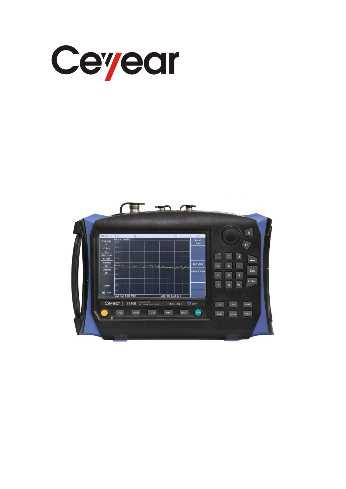
3680A/B
Cable & Antenna Analyzer
Quick Start Guide
China Electronics Technology Instruments Co., Ltd
Page 2
Preface
Thank you for choosing
3680A/B Cable & Antenna
Analyzer developed and
produced by China
Electronics Technology
Instruments Co., Ltd. As a
high-grade, precision and
advanced product, this
Analyzer has higher cost
performance of its kind.
We will assume trying our
best to meet your needs as
our responsibility to provide
high quality instruments for
you and also bring you firstclass after-sale service. We
always persist in “Good
Quality, Satisfied Service”
and promise to offer
satisfactory products and
service for you.
Manual No.
AV2.733.1040SK
Ver. No.
A.1 2014.9
China Electronics Technology
Instruments Co., Ltd
Manual Authorization
The information contained in
this guide is subject to change
without notice. And the
explanation right of all the
content and the terms in this
Guide belongs to China
Electronics Technology
Instruments Co., Ltd.
The copyright of the Guide
belongs to China Electronics
Technology Instruments Co.,
Ltd. Other entities and
individuals can’t change or
juggle it without our permission,
and can’t copy and spread for
earn business benefits. If
discovered, we have the right for
the legal action.
Product Warranty
From the date of production,
warranty period of this product
is 18 months. Within warranty
period, we will repair or replace
the damaged parts according to
the actual situations. This
requires user to return the
product back to the
manufacturer and prepay the
postage, which will be returned
together after maintenance.
Certificate of Quality
We ensure that this product
meets the indexes in the guide
from the date of production.
Calibration measurements will
be carried out and finished by
measurement unit with national
qualification, providing user
with relevant information for
reference.
Quality/Environment
Management
This product strictly adheres to
quality and environmental
management system in the
whole process from research and
development, manufacturing to
testing. China Electronics
Technology Instruments Co.,
Ltd has passed the ISO 9001 and
ISO 14001 system certifications.
Safety Precautions
“WARNING” denotes a
hazard. It calls attention to a
particular operating
procedure, method, or other
similar situations which, if
not correctly performed or
not adhered to, could result
in personal injury. Don’t
continue the next step until
you has fully understood
and met the indicated
warning conditions.
The sign of CAUTION
represents important
information tips, but no
danger. It calls attention to a
particular operating
procedure, method, or other
similar situations which, if
not correctly performed or
not adhered to, could result
in damage to the instrument
or loss of important data.
Don’t continue the next step
until you has fully
understood and met the
indicated attention
conditions.
WARNING
CAUTION
Page 3

Quick Start Guide for 3680A/B Cable and Antenna Analyzer
Contents
Chapter 1 Manual Overview ................................................................................. 1
Chapter 2 Ready for Use ....................................................................................... 2
2.1 Pre-operation Preparation ......................................................................... 2
2.2 Startup and utilization ............................................................................... 4
2.3 Front Panel ................................................................................................ 4
2.4 Operating interface .................................................................................... 7
2.5 Top Interface ............................................................................................. 7
2.6 Battery ....................................................................................................... 8
Chapter 3 Typical Application ............................................................................ 10
3.1 Calibration ............................................................................................... 10
3.2 Cable Test ............................................................................................... 12
3.3 Antenna Test ........................................................................................... 18
3.4 Universal Devices and Parts Test ........................................................... 19
3.5 Test Skills ................................................................................................ 20
Chapter 4 Ask for Help ....................................................................................... 25
4.1 Primary check ......................................................................................... 25
4.2 Help ......................................................................................................... 25
4.3 Return-to factory repairing method ........................................................ 26
Appendix I: Technical Indicators ........................................................................ 27
Appendix II: Accessories / Options List ............................................................. 28
Page 4

Quick Start Guide for 3680A/B Cable and Antenna Analyzer
Chapter 1 Manual Overview
This guide makes an all-round and three-dimensional introduction on the structure and use of 3680A/B
Cable & Antenna Analyzer (hereinafter referred to as 3680A/B or the Analyzer), from several aspects,
including instrument panel, power supply, startup, typical application, after-sales services, etc. Through this
guide, the reader can have a more systematic understanding on the Analyzer, and quickly grasp some basic
operations. For your proficiency of the instrument, please read the guide carefully and operate properly
upon instructions in the guide before operation.
Quick Start Guide for 3680A/B Cable & Antenna Analyzer contains chapters as follows:
Ready for Use
This Chapter introduces preparations before operation, startup, panel introduction, battery replacement,
etc., of 3680A/B. Through this chapter, you can acquire perceptual knowledge on 3680A/B on the whole,
and make a well preparation for appropriate and safe operation.
Typical Application
It introduces the calibration of 3680A/B in detail, and describes operating steps for basic measurement
formats of 3680A/B and gives a brief description on techniques used in the test, through test cases such
as cable testing, antenna testing, etc. By reading this chapter, you can use 3680A/B to finish some
typical DUT test by yourself.
Ask for Help
This Chapter contains two parts named after-sale maintenance and repair method, which emphatically
introduces the problem solving in the process of operation, maintenance, and repair of the instrument.
Page 5
Quick Start Guide for 3680A/B Cable and Antenna Analyzer
To prevent damage to the instrument, avoid electric shock, fire and personal
injury:
Do not open up the instrument without authorization
Do not attempt to disassemble or modify any part not described in this guide.
If disassemble it at your own discretion, it may cause various consequences
such as degradation of electromagnetic shielding performance and damage to
internal parts, thus affecting product reliability. If disassemble it without
authorization, even during the warranty period, we will no longer provide
free maintenance.
Warning
Chapter 2 Ready for Use
3680A/B Cable & Antenna Analyzer is designed with exquisite appearance and comfortable operation. It
has smaller volume, with the largest overall dimension being only 205mm (H) × 295mm (W) × 70mm (D);
and lighter weight, with the single unit weighing totally about 2.5kg (including battery), which is easy to
carry for field test. This Chapter will emphatically introduce the instrument’s test environment, power
supply, structure and battery replacement.
2.1 Pre-operation Preparation
This Section will describe the precautions before initial use of 3680A/B Cable & Antenna Analyzer. It
meets the requirements of security specified in GJB3947A-2009, please read the following safety
instructions carefully to avoid damage to the instrument or unnecessary personal injury.
2.1.1 Environmental Requirements
To ensure the service life and validity and accuracy of 3680A/B, please conduct testing under the following
conditions:
1. Temperature range: Storage temperature range: -40℃ ~ +70℃; operating temperature range: -10℃ ~
+50℃
2. Low pressure:
Low pressure (altitude): 0 ~ 4600m
2.1.2 Power Supply Requirements
3680A/B can be powered in three ways:
1、Powered by AC power supply and adapter
Page 6
Quick Start Guide for 3680A/B Cable and Antenna Analyzer
Power Supply Parameter
Applicable Range
Input Voltage
100V~240VAC
Rated Input Voltage
1.7A
Operating Frequency
50/60Hz
Output Voltage/Current
15.0V/4.0A
Operating voltage and frequency is subject to that indicated in the nameplate of
supplied power adaptor.
Rechargeable battery shall not be exposed to fire and high temperatures (above
70℃), or thrown into the fresh or salt water, and wetted, and shall keep away
from children.
Rechargeable batteries can be reused, and shall be placed in a suitable container
to avoid short circuit. The heavy metals such as nickel and chromium contained in
the battery may pollute the environment, so waste batteries should be placed in a
dedicated battery recycling bins rather than disposed at will ,.
Warning
Warning
AC-DC adapter provided together with the instrument must be used if adopting AC power supply. Input of
adapter is AC power supply with 100~240V, 50/60Hz.
When transported and carried by a backpack, the AC-DC adapter should not be connected with the
Analyzer in order to avoid overheating of the instrument. AC-DC adapter has a wide range of input voltage;
therefore when using, it should ensure the power supply voltage should be within the scope required in
Table 2.1.
Table 2.1 Power Supply Requirements
2. Powered by DC power supply
Voltage: 12V~18V (with battery uninstalled), 15V~18V (with battery installed)
Current: 2A (at minimum)
3. Powered by built-in battery
3680A/B can be powered by rechargeable lithium-ion batteries. If left unused for a long time, the battery
will self discharge, so it must first charge the battery before using it again. Refer to Section 2.6 for battery
usage details. The basic parameters of batteries provided together with the instrument are as follows:
Nominal voltage: 10.8V
Nominal volume ≥7000mAh
Page 7
Quick Start Guide for 3680A/B Cable and Antenna Analyzer
In this guide, the keys on the front panel are expressed with 【XXX】, XXX is
the key name; the menu button on the touch screen is expressed with [XXX],
XXX is menu name.
Warning
2.1.3 Electro-Static Discharge (ESD)
When using the instrument, please pay attention to ESD protection. Take the following precautions
to prevent static electricity if possible:
1. Before connecting the cable to the instrument for testing, the center conductor of the cable must be
grounded first. It can be achieved by following these steps: connect one end of cable with short circuit and
make the center conductor and outer conductor of the cable be short-circuited. When wearing an antistatic
wrist strap, please grasp the casing of cable connector, connect the other end of cable and then remove the
short circuit.
2. Ground yourself before cleaning test port of inspection instrument or connecting. It may be achieved by
grasping the metal casing of instrument grounded or the casing of connector of testing cable.
2.2 Startup and utilization
Prior to powering 3680A/B, please perform power supply instrument inspection following “Power
Requirements” in Section 2.1.2. Power for testing is allowed only after checked to be faultless.
Press the power ON/OFF key ( key) for about three seconds and then release the ON/OFF key after
hearing a sound of “beep”. It might take the Analyzer 20s to enter mainframe program. A warm-up for
15min is recommended before testing to keep the performance of internal components of instrument stable
for better testing results.
2.3 Front Panel
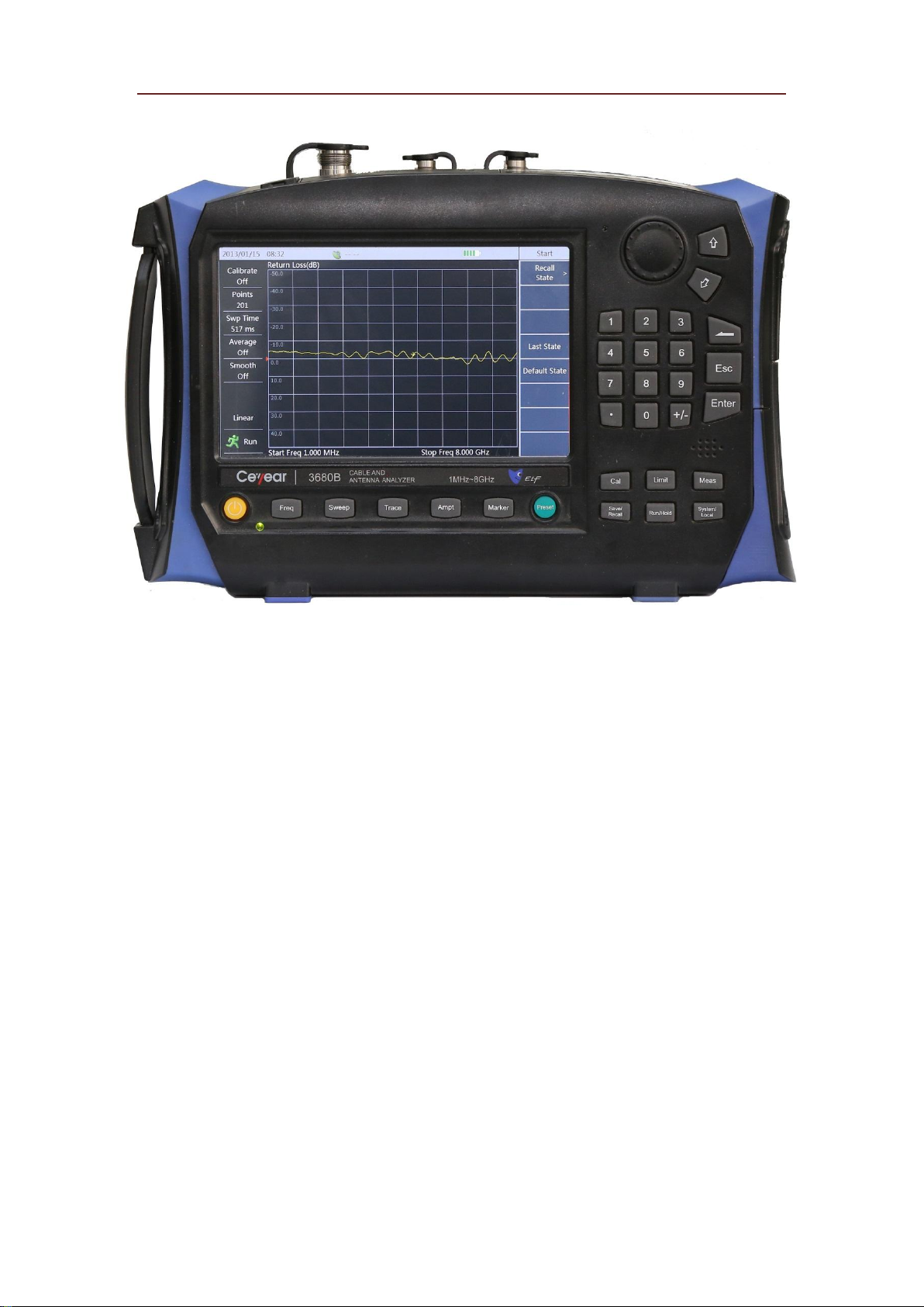
This Section provides a detailed introduction of the front panel of 3680A/B. Figure 2.1 is the front panel of
3680A/B.
Page 8
Quick Start Guide for 3680A/B Cable and Antenna Analyzer
Figure 2.1 Front panel of 3680A/B Cable & Antenna Analyzer
The features of common keys are described as below:
【Freq】: used for measurement parameter settings such as frequency parameter, signal standard, distance
parameter and velocity factor etc.
【Sweep】: used for measurement parameter settings such as trigger mode, scan mode, scan time, scan
points and average / bandwidth etc.
【Trace】: Realize contrastive function of memory trace and current data, including arithmetical operation
such as subtraction and division etc.; or store the current data as trace in memory.
【Ampt】: used for setting display area of Y-axis.
【Marker】: realize functions of marker, including settings like marker ON/OFF, marker mode, peak
search, and marker drag.
【Cal】: realize calibration, including calibration mode, calibration status ON/OFF and selection of
calibration kit models.
【Save/Recall】: used for file operations such as store and recall of measurement state, store and recall of
measured trace, screen capture, storage location and file copy etc.
【Limit】: realize limit functions, including limit ON/OFF, alarm ON/OFF, limit line edit, store / recall
and so on.
【Run/Hold】: used to switch between the results of consecutive switch and keeping current switch of
Analyzer.
【Meas】: Measurement format setting and single / double window switching etc.
【System/Local】: When the Analyzer is in local operating mode, it is used for setting system status, such
as mode switching between cable and antenna analyzer and power test, setting of date, time, power saving
mode, viewing the product serial number and instrument applications version number etc.; when the
Analyzer is in control mode, it is used for switching to local operating mode.
Numerical (character) key: used for inputting numbers or characters
Page 9
Quick Start Guide for 3680A/B Cable and Antenna Analyzer
Instrument
Status
LED status
Physical state of Analyzer
Off state
Off
a) The battery has been installed; not connected to the power
supply.
b) The battery has not been installed; not connected to the
power supply.
Constant yellow
a) Battery has not been installed; connected to power supply.
b) The battery has been installed and full; connected to power
supply.
Flashing yellow
The battery has been installed and not full; connected to
power supply.
On state
Constant green
a) The battery has not been installed; connected to power
supply.
b) The battery has been installed and full; connected to power
supply.
c) The battery has been installed battery; not connected to
power supply.
Flashing green
The battery has been installed and not full; connected to
power supply.
【↑】and【↓】: Represent up and down respectively and used to control step or select current options.
【←】backspace key: used to delete the last entered number or character.
【Cancel】: Used to cancel parameter setting and close the input tag.
【Enter】: is used to confirm parameter settings.
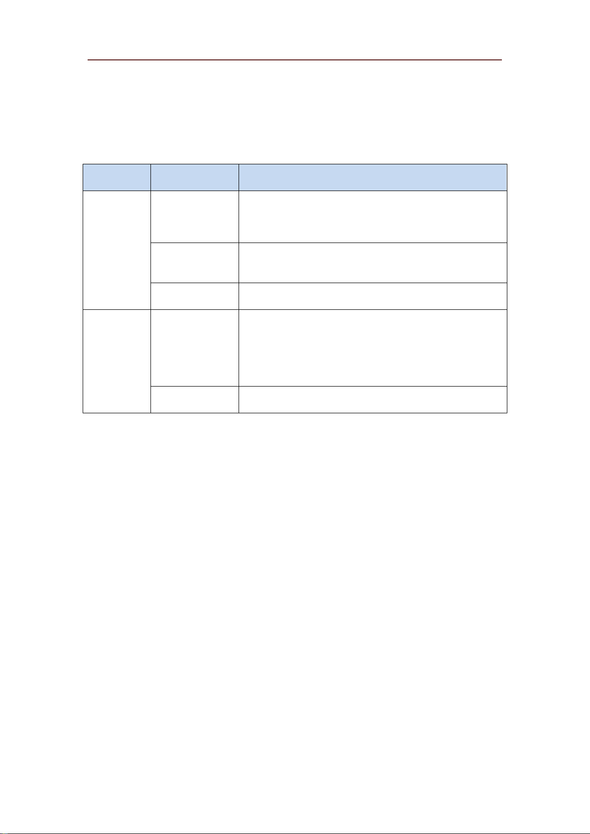
LED indicator: with yellow and green two colors, the physical state of the instrument corresponding to the
color is as shown in the following table.
Table 2.2 LED Status Description
Page 10
Quick Start Guide for 3680A/B Cable and Antenna Analyzer
Power interface
GPS antenna port
10MHz I/O port
Port 1
SD card slot
LAN
interface
Mini
USB
USB A-type interface
2.4 Operating interface
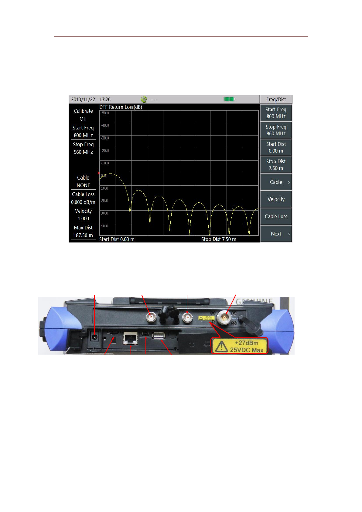
3680A/B is provided with a 7-inch HB TFT true color LED with the function of touch screen and supports
soft-key operations of applications through touch screen. The operating interface is as shown in Figure 2.2.
3680A/B provides different interfaces with different color contrast corresponding to different testing
environment such as outdoor, nighttime, and normal testing environment; In addition, this instrument also
supports automatic adjustment of brightness, hibernation, and automatic shutdown.
Figure 2.2 Operating Interface of 3680A/B Cable & Antenna Analyzer
2.5 Top Interface
3680A/B top panel is composed of three parts, including power interface, digital interface and the test port.
Figure 2.3 Top interface of 3680A/B Cable & Antenna Analyzer
2.5.1 Power interface
Power supply interface of the instrument supplies power for the Analyzer with DC output of AC-DC
adapter or DC power. Inner conductor of external power interface is anode, and outer conductor is
grounded.
2.5.2 Test port
1. GPS antenna port: Connect GPS antenna equipment and support positioning of the current location of
Analyzer.
2.10MHz I/O port: can be used to provide 10MHz signal for the Analyzer as reference signal by connecting
Page 11
Quick Start Guide for 3680A/B Cable and Antenna Analyzer
Warning
with other external instrument; output 10MHz reference signal inner Analyzer for the use of external
instrument.
3. Port 1: or know as test port, is used in cable or antenna test. Characteristic impedance is 50Ω, N-type
female port.
In order to protect the instrument better, the test port of instrument provides
some identification symbols, users shall pay attention on their meanings to
avoid permanent damage to the instruments.
Detailed description of instrument symbols are as described in Section 2.5.4.
2.5.3 Digital Interface
1. SD card slot: Micro SD card slot can be used in memory space extension of the instrument.
2. LAN (network) interface: a 10/100Mbps network interface, can be used to connect a computer (PC) via a
network cable, related tools and software then can be operated by PC to perform program control and data
transmission to 3680A/B.
3. Mini USB interface: connect an external PC, then related tools and software can be operated by PC to
perform program control and data transmission to 3680A/B.
4. A-type USB port: connect external USB equipment, such as USB storage device, USB mouse and
keyboard.
2.5.4 Instrument symbol
Instrument symbol shown in the picture (yellow label) means that the maximum input power of test port 1
is +27dBm; the maximum input DC level is 25VDC. Do not connect signals beyond this range to the port
in use, which could burn the instrument!
2.6 Battery
3680A/B is equipped with a rechargeable lithium-ion battery with a large capacity with operating time of
up to more than 8 hours for 3680A and 4 hours for 3680B. In order to assure the service life, the battery
shall be taken out of the battery compartment in transport and long-term storage. Buying stand-by
batteries of the same model with the original one is recommended if long-time field test is performed.
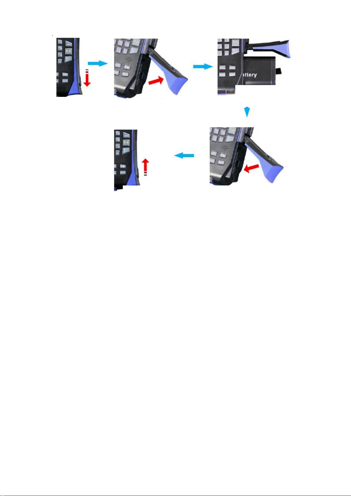
The mounting or replacement of the battery of 3680A/B is easily performed as shown in Figure 2.4.
Page 12
Quick Start Guide for 3680A/B Cable and Antenna Analyzer
Pull down
battery cover
Open battery cover
Mount/ Pull out
the battery
Close battery cover
Push up battery cover
Figure 2.4 Battery Mounting or Replacement
In addition, for those dead batteries, charging time in OFF state is about 4 hours.
Page 13
Quick Start Guide for 3680A/B Cable and Antenna Analyzer
Chapter 3 Typical Application
3680A/B offers many measurement formats, and this Chapter will make a detailed instruction on
operation steps of several basic measurement formats by three test cases.
3.1 Calibration
To ensure accuracy of test results, the instrument needs to be calibrated before test to eliminate the errors.
3680A/B adopts mechanical calibration method, whose calibration process is as follows:
1. Press 【CAL】 to enter the calibration menu.
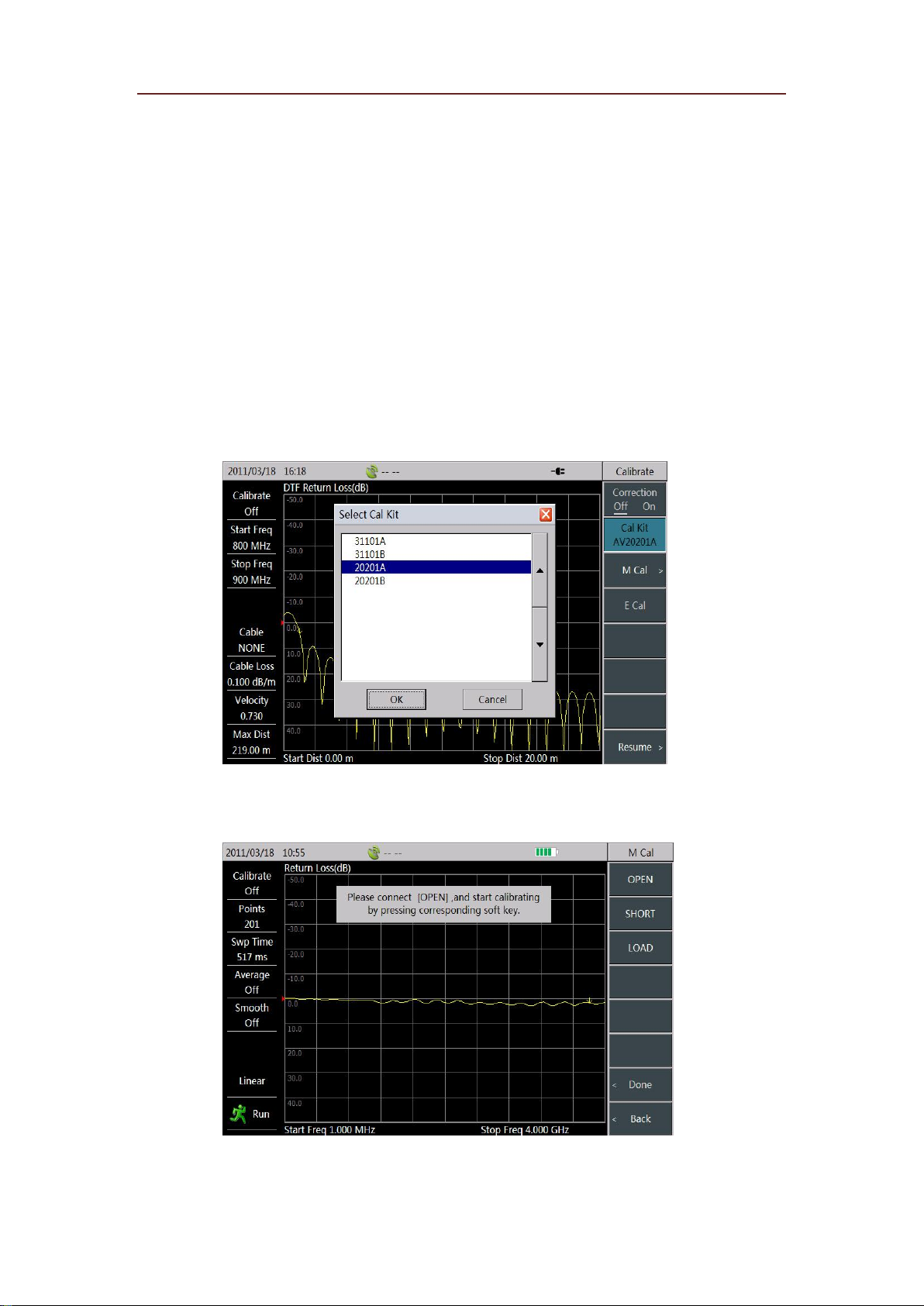
2. Select [Cal Kit] menu, then choose the matched model of calibration kit from “Select Cal Kit” list
popped up in the screen, and select the “Enter” key or press 【Enter】 to finish the calibration kit selection,
as shown in Figure 3.1.
Figure 3.1 Selection of Calibration Kit Model
3. Select [M Cal] menu to calibrate the Analyzer following by screen tips. After that, Analyzer’s software
will give calibration prompt instructions, as shown in Figure 3.2.
Figure 3.2 Mechanical Calibration Prompt
Page 14
Quick Start Guide for 3680A/B Cable and Antenna Analyzer
Specific mechanical calibration procedure is as follows:
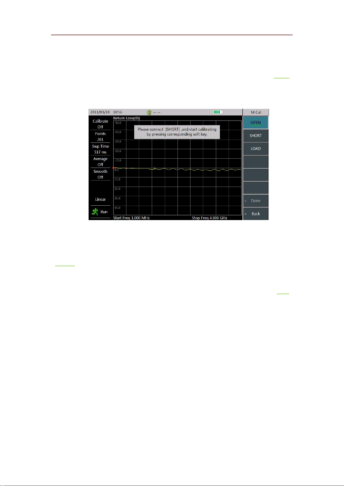
Connect the open to the test port and select the [OPEN] menu. At this time, the screen will
automatically prompt “[OPEN]Measuring……”. When the [Open] menu becomes into [OPEN], it
indicates the completion of the open circuit calibration. Figure 3.3 below indicates the completion of
open circuit measurement.
Figure 3.3 Completion of Open Calibration
Connect the short to the test port and select the [Short] menu. At this time, the screen will
automatically prompt “[SHORT]Measuring ……”. When the [SHORT] menu becomes into
[SHORT], it indicates completion of the short circuit calibration.
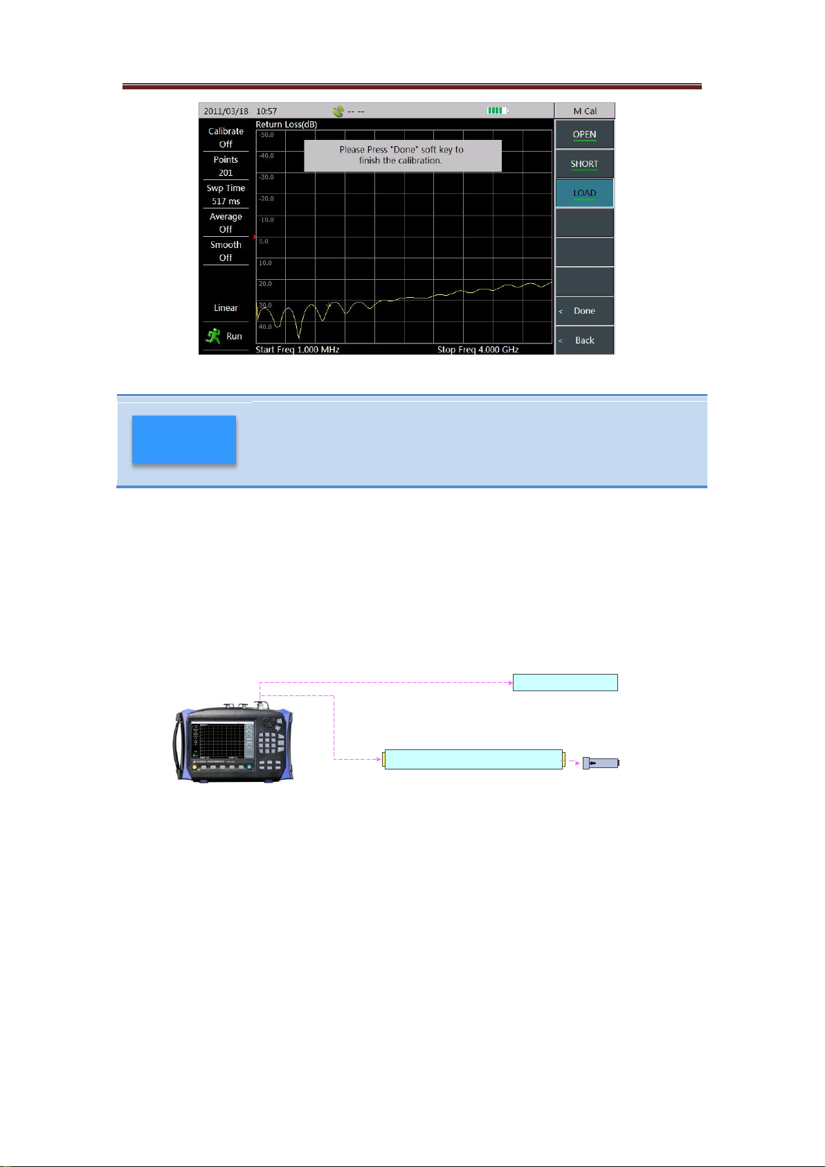
Connect the load to the test port. Then, select the [Load] menu, at this time, the screen will
automatically prompt “[LOAD]Measuring……”. When the [Load] menu becomes into [Load], it
indicates completion of the load calibration, as shown in Figure 3.4. At this moment, select the
[Done] menu to finish mechanical calibration process.
Page 15
Quick Start Guide for 3680A/B Cable and Antenna Analyzer
In the real calibration process, open circuit, short circuit and load may be
measured by any sequence, without following that in the present example.
menu to finish the calibration after all three states are
calibrated.
CAUTION
Figure 3.4 Calibration Completion
Select [Done]
3.2 Cable Test
3.2.1 Return Loss/VSWR Measurement
Return Loss/Voltage Standing Wave Ratio (VSWR) is a representation of the reflection characteristic. In
engineering applications, this Analyzer can test the return loss or VSWR of single-port or double-port
devices, which is separately shown as (1) and (2) in Figure 3.5.
( 1 )
( 2 )
Device Under Test
Cable & Antenna Feeder System
Match Load
Figure 3.5 Connection method for Return Loss/VSWR Measurement
3680A/B mainly tests RF cable. Take the cable with length of 25m, radio frequency of 2.1GHz and
VSWR of 1.05 as an example, this part makes a detailed instruction on test steps of return loss
(Measurement steps of return loss and VSWR test are the same, therefore, it only takes return loss
measurement as example here).
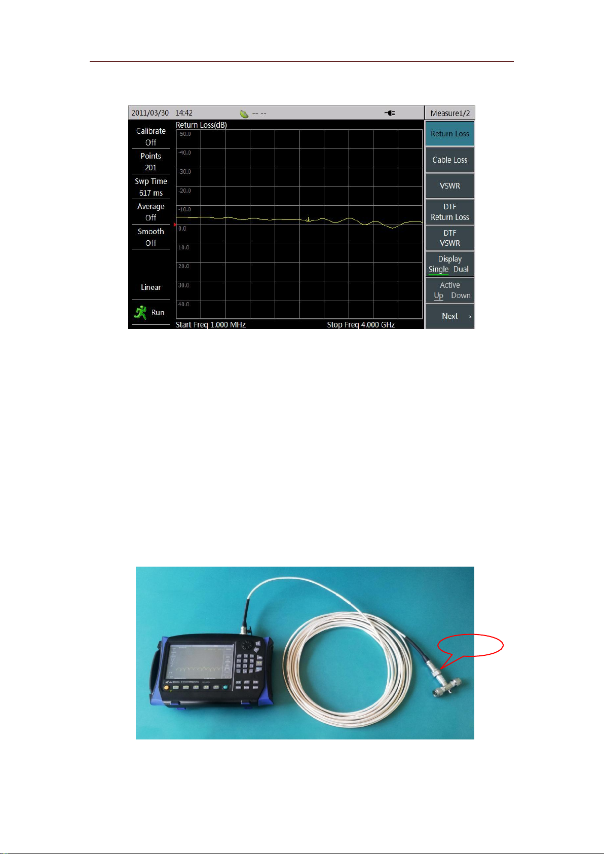
1. Press【MEAS】to enter the measurement menu;
2. Select [Return Loss] menu to set the current measurement format of instrument as “Return Loss”, as
shown in Figure 3.6.
Page 16
Quick Start Guide for 3680A/B Cable and Antenna Analyzer
Figure 3.6 Selection of Measurement Format
3. Press 【FREQ】 to enter the frequency menu; select [Start Freq] menu, then use the numeric keys, knob
or arrow keys to input the start frequency value and select the corresponding unit menu to complete the
input; the frequency in this example is set to 1MHz.
4. Similar to step 3, set the stop frequency needed by the measurement; the frequency in this example is set
to 4GHz.
5. According to the Section 3.1 in this Chapter, calibrate at port 1 of the instrument;
6. After the Port 1 is calibrated, connect the measured cable to the Analyzer and link match load to other
end of the cable, as shown in Figure 3.7. The Analyzer will display the measured return loss curve.
Matched Load
Figure 3.7 Return Loss or VSWR Test Connection Diagram
7. You can adjust the amplitude display for easy observation by methods implied in Section 3.5; then,
Page 17
Quick Start Guide for 3680A/B Cable and Antenna Analyzer
Return loss or VSWR is the matching degree of DUT at each frequency point
in the whole frequency band. Sweep span can be specifically set according to
press 【Marker】 to turn on marker function, so that you can check the return loss conditions of the cable
at each frequency.
CAUTION
operating frequency of the measured cable or DUT during measurement.
3.2.2 Cable Loss Measurement
Cable loss refers to the energy consumed by cable in the process of signal transmission, which is generally
represented by average value. During the test, the cable loss is usually measured by the following
connection, as shown in Figure 3.8.
Figure 3.8 Cable Loss Measurement Connections
Now, this part takes the cable with length of 25m, frequency of 2.1GHz and cable loss of 0.36dB/m to
introduce the cable loss test steps.
1. Press 【Meas】 to enter measurement menu;
2. Select [Cable Loss] menu to set the current measurement format of instrument as “Cable Loss”.
3. Press 【Freq】 to enter the frequency menu; select [Start Freq] menu, then use the numeric keys, knob
or arrow keys to input the start frequency value and select the corresponding unit menu to complete the
input; the frequency in this example is set to 1MHz.
4. Similar to step 3, set the stop frequency needed by the measurement; the frequency in this example is set
to 4GHz.
5. According to the section 1 in chapter 3, calibrate at port 1 of the instrument;
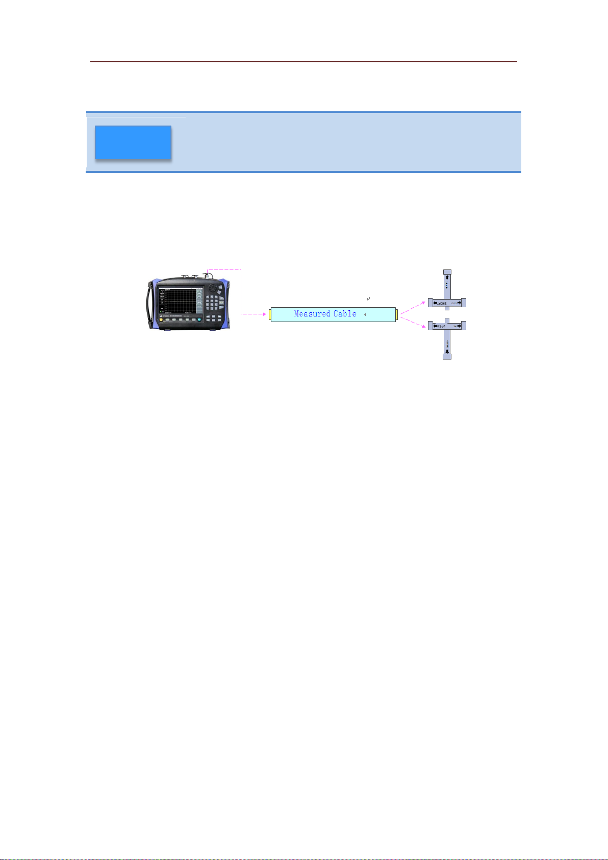
6. After the Port 1is calibrated, connect the measured cable to the Analyzer to ensure the accuracy of cable
loss measurement. Terminal of the measured cable shall connect to the open circuit or short circuit, as
shown in Figure 3.9.
Page 18
Quick Start Guide for 3680A/B Cable and Antenna Analyzer
Open/Short
Figure 3.9 Cable Loss Test Connection Diagram
Cable loss curve of the measured cable can be obtained through above steps. The so-called average loss
refers to average the measured extreme values of loss. Users can use 【Marker】 to find peak value and
valley value of the loss curve, then average them, and finally obtain the average loss of the cable. Limit
value search process is as follows:
Press 【Marker】 to enter the marker menu, and the Marker 1 defaults to be in open state at this time;
Select [Peak] menu to place Marker 1 onto the peak position of the cable loss curve;
Select [Marker 1 2 3 4 5 6] menu again, the menu becomes into [Marker 1 2 3 4 5 6] at this time, and
then select [Marker Off On] menu to open Marker 2;
Select [Valley] menu to place Marker 2 onto the peak position of the cable loss curve;
Upon the cable loss values shown by Marker 1 and Marker 2, sum and average them to obtain average
loss of the cable.
Page 19
Quick Start Guide for 3680A/B Cable and Antenna Analyzer
3.2.3 DTF Measurement
DTF (Distance To Fault) measurement, also called fault point location measurement, is a kind of
performance verification and fault analysis tool in the maintenance and repair process of antenna and
transmission line. DTF function of 3680A/B is realized by adopting the measurement technique named
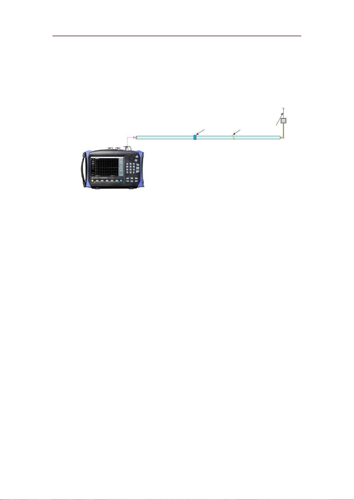
Frequency-Domain Reflectometry. In engineering applications, DTF measurement usually adopts the
connection type shown in Figure 3.10 to measure the fault point status of connection cables of devices
such as base stations, etc.
Antenna
Connector Fault Point
Figure 3.10 DTF Measurement Connections
3680A/B provides two measurement formats including DTF return loss and DTF VSWR. As for their
difference, we will not explain here again for it is similar to the difference between return loss and VSWR.
We will make a detailed introduction for measurement steps on cable length and return loss at each point,
through taking the cable with length of 25m, velocity factor of 0.76 and cable loss of 0.26dB/m.
1. Press 【Meas】 to enter the measurement menu;
2. Select [DTF Return Loss] menu to set the current measurement format to “DTF Return Loss”.
3. Press 【Freq】 to enter the frequency menu; select [Start Freq] menu, then use the numeric keys, knob
or arrow keys to input the start frequency value and select the corresponding unit menu to complete the
input; the frequency in this example is set to 1GHz.
4. Similar to step 3, set the stop frequency needed by the measurement; the frequency in this example is set
to 2GHz.
5. Press 【Sweep】 to enter Sweep menu; select [Point] to set the required sweep point, which is set to
401 here.
6. Select [Start Distance] menu, input appropriate measurement start distance by the numeric keys, knob
or arrow keys, and then select the unit menu [Meter] to finish the setting.
7. Similar to step 6, set the measurement stop distance. Once the test points and frequency are set, the
current maximal test distance of Analyzer is determined (it is displayed in the lower left corner of the
screen) too. Users can adjust stop distance based on this value and estimated position of measured fault
points. If the current maximum distance is less than the measurement distance, sweep span and points can
be properly adjusted. Detailed explanation can be found in “DTF Measurement Distance & Resolution”
Page 20
Quick Start Guide for 3680A/B Cable and Antenna Analyzer
Velocity factor and cable loss are inherent parameters of cable, if any
further questions, please check the cable instructions or consult the
cable manufacturer.
CAUTION
part in Section 3.5 of this Chapter.
8. According to Section 3.1 in this Chapter, calibrate port 1 of Analyzer;
9. Press 【Freq】->[Velo Factor] to set velocity factor of DUT, which is the transmission speed and light
speed of electromagnetic wave in the cable, is between 0~1.
10. Select [Cable Loss] menu, and set cable loss of the measured cable according to the known parameters
of DUT.
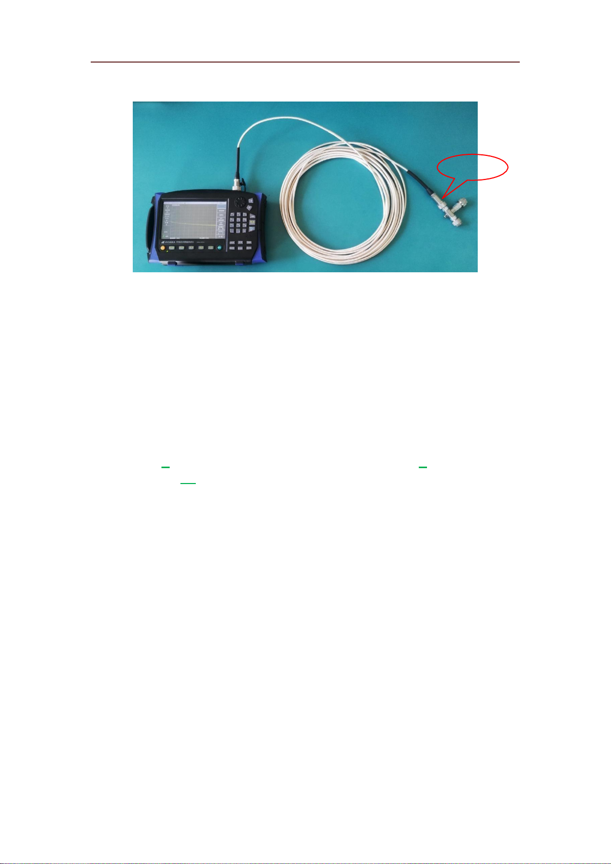
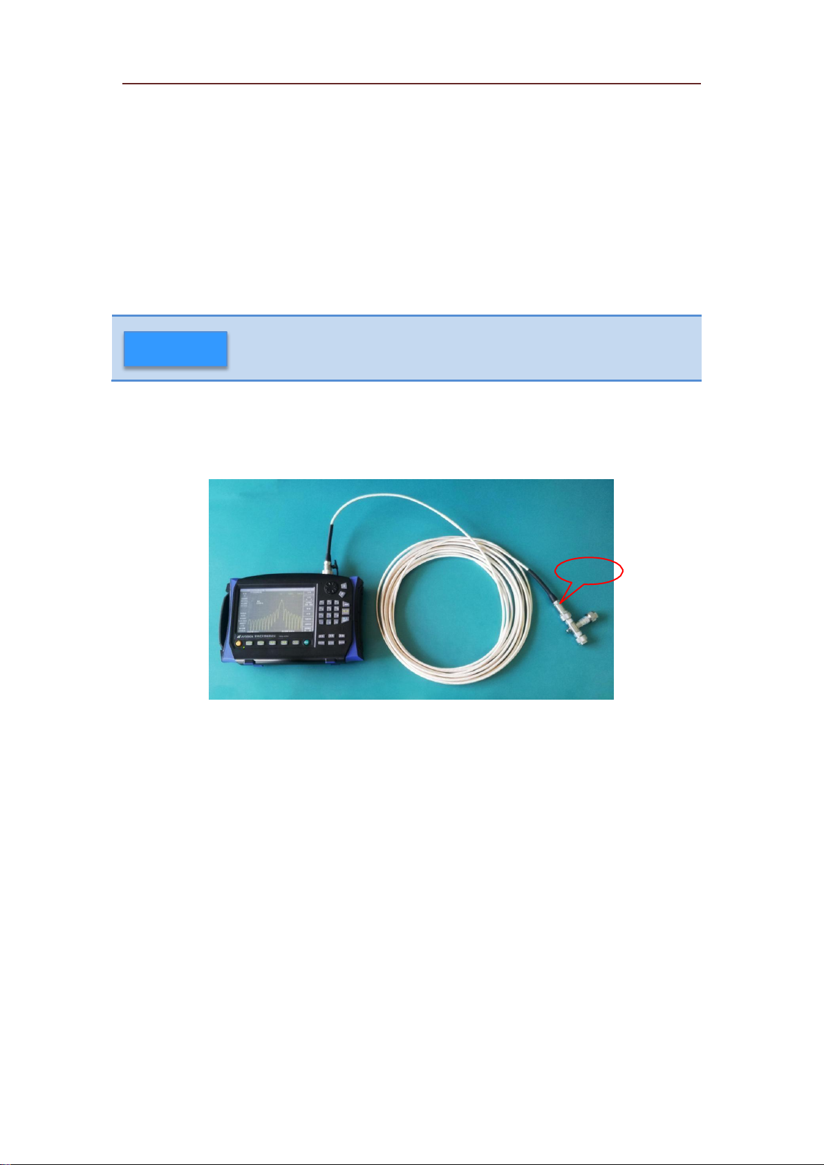
11. DTF return loss curve can be measured and obtained by connecting DUT to Analyzer and then link the
mismatch load or open circuit to the end of the cable (as fault point). DTF return loss test connection is as
shown in Figure 3.11.
Open circuit
Figure 3.11 DTF Return Loss Test Connection Diagram
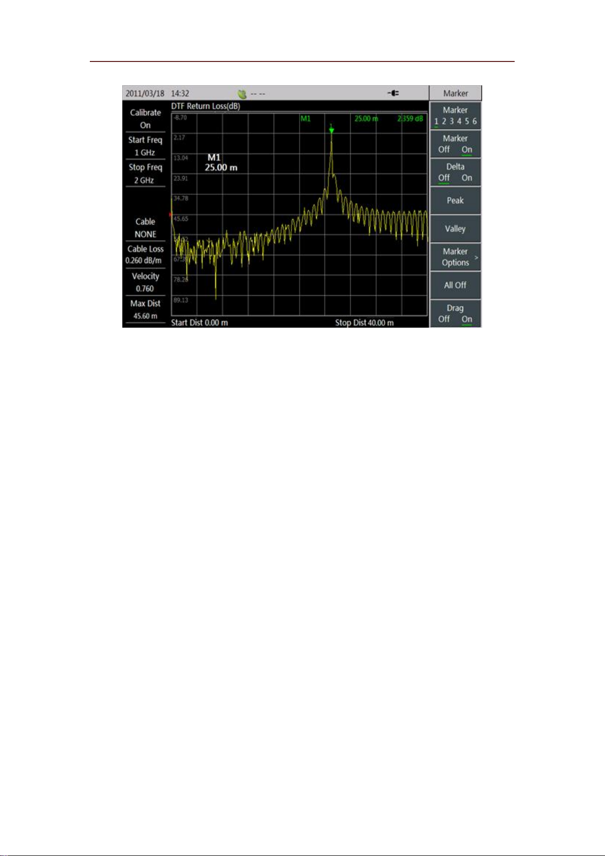
12. Press 【Marker】 to enter the marker menu, Marker 1 has been turned on at this time. Select [Peak]
menu to place Marker 1 onto peak value (namely fault point), in order to read out the location of fault
point, that is the distance from fault point to measurement port of Analyzer. At 25m length of this cable
exampled here, we measure that DTF return loss is 2.359 which indicates that the length of cable is
25m. Or, you can check DTF return loss at each position by moving the marker. Fault points measured
here are shown in Figure 3.12.
Page 21
Quick Start Guide for 3680A/B Cable and Antenna Analyzer
Figure 3.12 Measurement on Length of Cable
3.3 Antenna Test
3680A/B can test the return loss/VSWR of general passive receiving antenna. This part will introduce the
measurement process of passive antenna by taking terminal antenna TZD-P021Z05-195 as an example.
Terminal antenna TZD-P021Z05-195 is kind of receiving antenna with frequency of 2,100MHz, whose
standing wave is minimum at 2,100MHz in theory.
1. Press 【Meas】 to choose “Return Loss” or “VSWR” as the measurement format of Analyzer.
2. Press【Freq】to set instrument frequency measurement range by contrasting with receiving frequency
range of the antenna to be received; if the frequency range of antenna is not clear, users can measure return
loss/VSWR according to system default measurement range (1MHz~4MHz), which is set to 2GHz ~
2.2GHz here.
3. As the antenna has interface with diameter of 3.5mm, N-3.5mm adapter needs to be connected to the
test port of Analyzer, and then use the calibration kit (option) with diameter of 3.5mm to calibrate the
Analyzer as described in section 3.1.
4. After calibration, connect the measured antenna to Analyzer as shown in Figure 3.13.
Page 22
Quick Start Guide for 3680A/B Cable and Antenna Analyzer
Figure 3.13 Antenna Measurement Connection Diagram
Make corresponding adjustment on the displayed amplitude according to amplitude set-method described
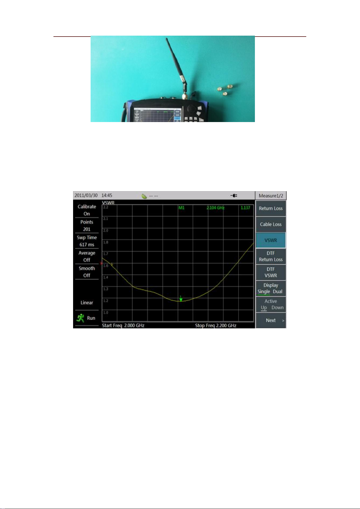
in section 3.5; then press 【Marker】 to turn on the marker function, so that you can see the VSWR
situation of antenna at each frequency. Through observation we can find that VSWR of antenna is smaller
near 2,100MHz, with minimum at 2,104MHz.
Figure 3.14 VSWR Test of Terminal Antenna TZD-P021Z05-195
3.4 Universal Devices and Parts Test
Addition to cable and antenna test, 3680A/B can also be used for testing the attenuation, cable connectors,
cable joints, etc. This part will measure the return loss of 10dB attenuation, as an example, with
operations as follows:
1. Press 【Meas】 to choose “Return Loss” as the measurement format of Analyzer.
2. Press 【Freq】 to set measurement range of Analyzer according to the working frequency range of
attenuator; if the frequency range of attenuator is not clear, users can measure the return loss/ VSWR
according to the system default frequency range (1MHz ~ 4GHz).
3. As the attenuator to be measured has interface with diameter of 3.5mm, N-3.5mm adapter needs to be
Page 23
Quick Start Guide for 3680A/B Cable and Antenna Analyzer
connected to the test port of Analyzer, and then use the calibration kit (option) with diameter of 3.5mm to
calibrate the Analyzer as described in section 3.1.
4. After calibration, connect the measured attenuator to Analyzer and the match load to the terminal of
attenuator as shown in Figure 3.15.
Figure 3.15 Attenuator Measurement Connection Diagram
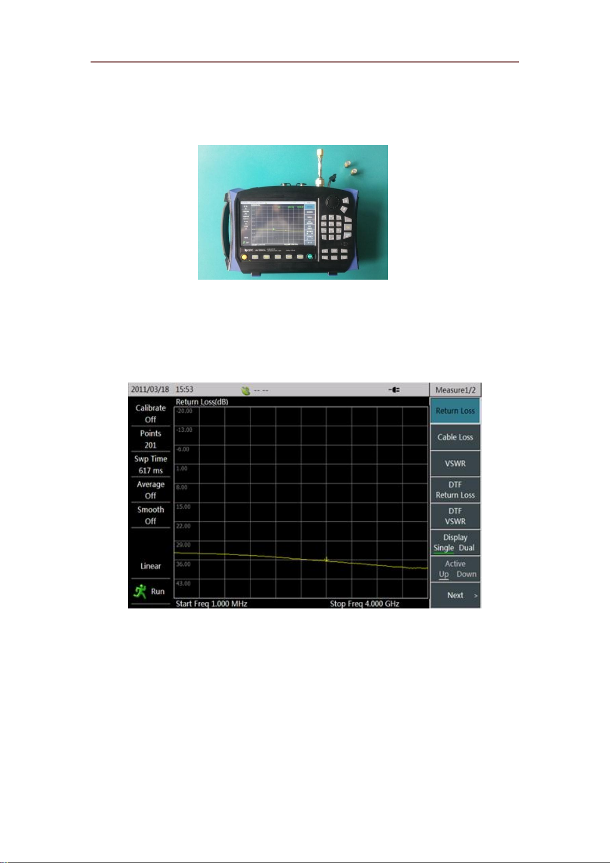
Make some corresponding adjustments on the displayed amplitude according to amplitude set-method
described in Section 3.5; we can find that the return losses of attenuator are all below 30dB. Based on the
test data, designer can confirm attenuator index by contrasting with design index, as shown in Figure 3.16.
Figure 3.16 Return Loss Test of 10dB Attenuator
3.5 Test Skills
As there have given a detailed description to the test steps for several test formats, this part will make a
brief introduction on some common skills used in the measurement process.
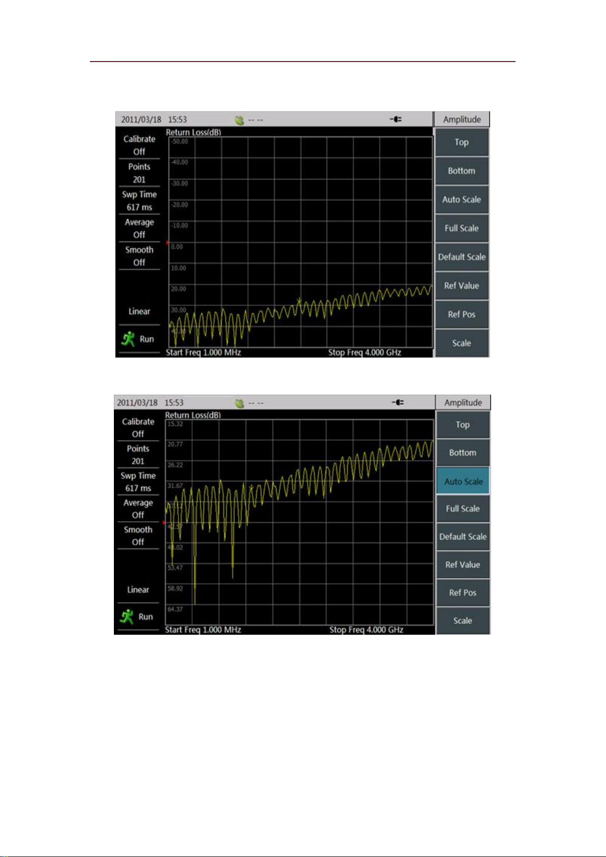
1. Amplitude: 3680A/B provides three ways for amplitude adjustment: First, through the top and bottom
adjustment; Second, through automatic ratio adjustment; Third, through the adjustment on reference
value, location and ratio. In order to make a clearer and more intuitive observation on the measured curve,
the amplitude of displayed curve can be adjusted by adopting any ways under 【Amptd】. After
Page 24
Quick Start Guide for 3680A/B Cable and Antenna Analyzer
automatic ratio adjustment of default scale and amplitude, the measured return loss curve exampled in
Section 3.2 is displayed as in Figure 3.17 and Figure 3.18.
Figure 3.17 Return Loss Curve under Default Scale
Figure 3.18 Return Loss Curve after Automatic Ratio Adjustment
2. Limit line: Users have their own eligibility criteria in batch test. In this regard, 3680A/B provides
【Limit】 function for the setting of limit line, making it easier to test products. Thus, when large
quantities of products need to be tested, it only needs to replace DUT and observe limit line to judge
whether the product is qualified or not. If the limit line is red, DUT is disqualified; if the limit line is green,
DUT is qualified. What’s more, it can avoid repetitive edit by saving/recalling the limit line. Limit line in
Figure 3.19 has been edited.
Page 25

Quick Start Guide for 3680A/B Cable and Antenna Analyzer
Figure 3.19 Limit Line in Use
3. Alarm: The Analyzer also has alarm function that users can turn on or off this function by [Alarm
Off On] when limit line is in use. If test curve of DUT exceeds the set limit line when the alarm
function is turned on, Analyzer will raise a “beep ... beep” alarm, through which users can judge
whether the product is qualified or not. Test curve in Figure 3.20 has exceeded the set limit line.
Figure 3.20 Alarm for Limit Line When Overstepping the Boundary
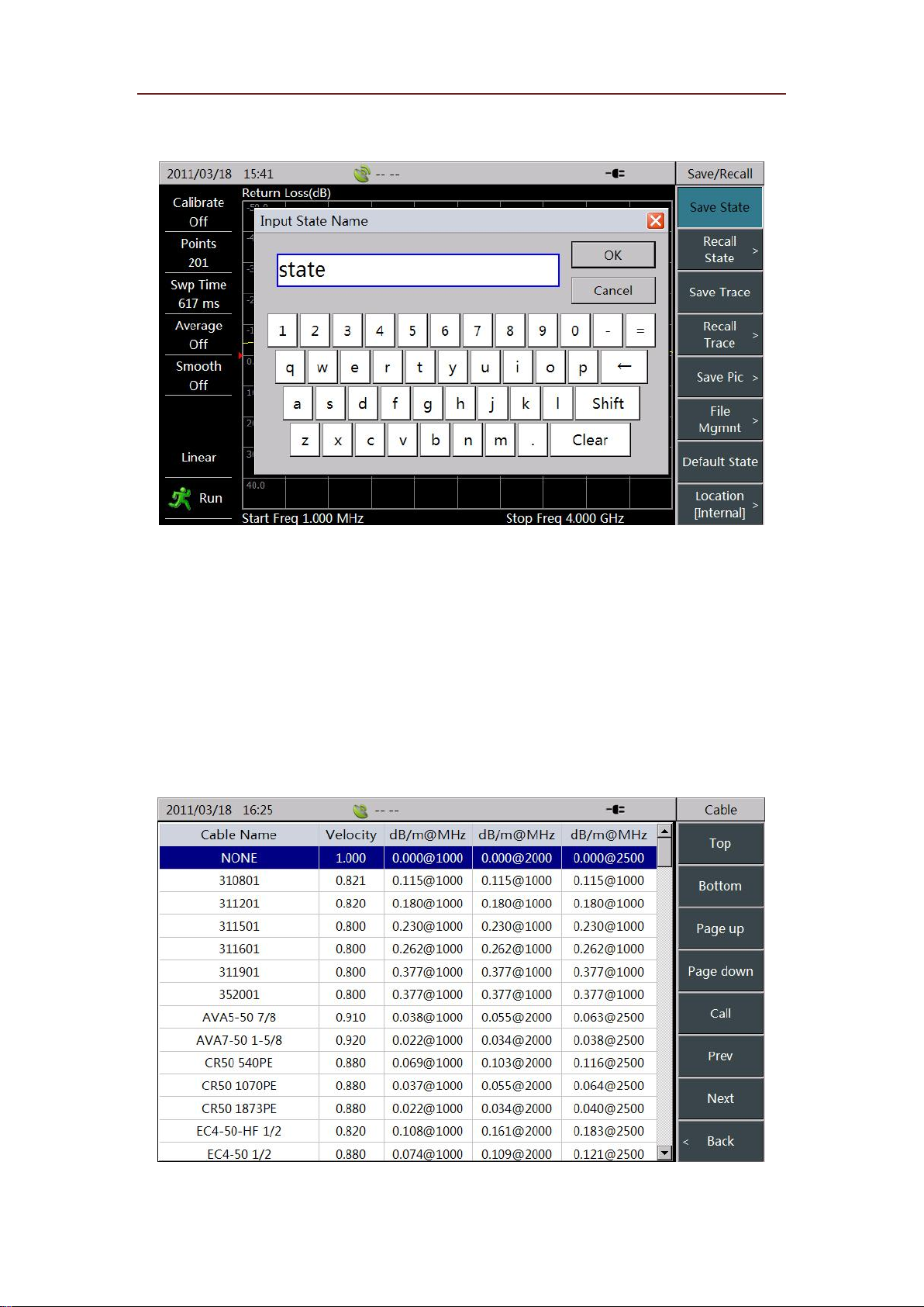
4. Store/Recall: 3680A/B provides store/recall function, for saving and recalling the measurement state,
trace and pictures to meet the requirements of users when they writing the subsequent report, checking
the state, analyzing the data, etc.
Page 26
Quick Start Guide for 3680A/B Cable and Antenna Analyzer
Figure 3.21 Return Loss Curve Measured Store
5. Cable Model: It has given detailed steps for setting velocity factor and cable loss in DTF test. To make
it easier to test and set parameters, 3680A/B offers a series of common cable models for user’s recall.
Users can directly use [Cable Model] menu in the menu bar of 【FREQ】 to enter the interface for cable
model selection. Then select the corresponding cable model through the touch screen, knob or arrow keys,
choose [Recall] menu or press 【Enter】 key to complete recall of cable models. Thus, Analyzer will
automatically match parameters for the selected cable based on its model, including velocity factor, cable
loss, etc. Cable model recall interface is shown in Figure 3.22.
Figure 3.22 Cable Model Select
Page 27

Quick Start Guide for 3680A/B Cable and Antenna Analyzer
In addition, in the menu of cable models, this Analyzer also provides [Head], [Foot], [Page Up] and [Page
Down] menu to make it easier to search cable model.
6. DTF measurement distance and resolution: In DTF analysis, measurement distance is influenced by
sweep span and sweep points of frequency as well as transmission speed of electromagnetic wave in the
cable to be measured. The smaller the sweep span is, the longer the measured maximum distance will be.
The more the sweep points are, the longer the measured maximum distance will be.
In terms of cable loss, nominal value of effective directionality of 3680A/B is equal to or more than 42dB.
If the reflected signal energy is less than the effective directionality, the valid test result is not available.
DTF measurement resolution is related to frequency sweep span. The wider the sweep span is, the higher
the resolution will be.
Page 28

Quick Start Guide for 3680A/B Cable and Antenna Analyzer
Chapter 4 Getting Help
Under normal circumstances, problems are caused by hardware, software, or improper operation of users. If
there are any problems, first observe error messages and store them; analyze the possible reasons and use
the methods provided in “4.1 Basic check” as reference and perform primary check to solve the problems.
You can also contact our customer service center and provide error messages collected. We will assist you
in solving problems as fast as we can. Please check 4.2 for detailed contact information or via
www.ceyear.com online for the nearest technical support contact information.
4.1 Basic check
If any problem occurs in the 3680A/B you are using. You can check them yourself in accordance with
the following guidance. If the problem persists, please contact us.
If 3680A/B cannot be started after pressing startup key, please check whether the power supply is
normal. Check whether the indicators of adapter are powered on, or whether the power of battery is
with electricity. If nothing wrong with the aforementioned problems, then it might be an instrument
failure, please contact us for return-to-factory repair.
Please press 【Reset】 key and return to a known state, if you cannot enter into the system or
application programs after 3680A starts up. If it still cannot work normally, then it might be an
instrument failure, please contact us for return-to-factory repair.
If 3680A/B fails to start up and self test, please press 【Reset】 key, which makes 3680A/B return to
a known state. If the self test still fails then it might be an instrument failure, please contact for returnto-factory repair.
If the touch screen of 3680A/B does not respond, please use the key combination (【System/Local】
+ 【↑】) and perform recalibration towards the touch screen (【System/Local】 → [Settings] →
[Touch Screen Calibration]), if the problem on touch screen response persists then it might be an
instrument failure, please contact for return-to factory repair.
If 3680A/B performance index is not normal, please check whether the testing tools and testing
environment meet the requirements; whether the test port connectors are worn out; whether the
performance index of calibration kits are normal. If nothing wrong with the aforementioned problems,
then it might be an instrument failure, please contact for return-to factory repair.
If 3680A/B cannot communicate via LAN, first confirm the IP address setting of Analyzer and then
check the yellow LED indicator next to LAN interface on the rear panel. If this indicator does not
flash then check LAN cable and connection.
4.2 Help Information
3680A/B provides “Error log” function, when a problem occurs, the instrument will automatically generate
“Error log”, which records the abnormities of hardware, file deletions, program control etc.; it is composed
of three levels, including message, warning, and error and used for assisting in analyzing instrument failure.
Users can view “Error log” via 【System/Local】→ [Page Down] → [Error log].
Page 29
Quick Start Guide for 3680A/B Cable and Antenna Analyzer
Tel:
+86-0532-86896691
Website:
www.ceyear.com
E-mail:
Hereby declares! Full responsibility shall be taken at your own risk in case
the damages to the instrument or personal injury are caused by misoperation
or improper operation occurred.
Warning
In addition, the customer service support center is ready to help users at anytime. Points of sales and offices
have been set up all over the country. Technical support personnel located there can provide services such
as rapid on-site technical exchange with customers, training, and product maintenance etc. We can provide
comprehensive and convenient technical support and related services for your convenience.
In addition, you can also log in on www.ceyear.com and use QQ online customer service to perform online
counseling.
The instruments we supplied have been checked by quality and security departments to be qualified. We
guarantee an 18-month warranty and long-term maintenance; free maintenance for those instruments under
warranty, damaged for reasons excluding man-made causes; fees will be charged for those after warranty
based on maintenance costs. Different methods such as telephone or home maintenance etc. will be adopted
to solve your problems.
In addition, please contact us in time if instrument failure occurs, we will provide assistance required.
Return-to-factory repair is also supported if necessary. Users are forbidden to disassemble the instrument
by themselves in case damages to internal circuits and parts caused by misoperation.
4.3 Repair Method
When your problems with 3680A/B appear difficult to solve, you can contact us by phone or fax. If you
confirm that the instrument needs to be repaired, please follow the steps below to package the instrument:
1) Write a paper document describing the instrument failure and put it in a packing case with the Analyzer;
2) Package the instrument with original packaging materials to reduce potential damage;
3) Place gaskets in the four corners of the outer carton and place the instrument inside the outer packaging
case;
4) Seal the mouth of packaging case with glue and reinforce the packaging case with nylon tape;
5) Mark “Fragile! Do not touch! Handle with care!” on the box;
6) Consign this instrument in conformity with precision instrument and keep all copies of transport
document.
Page 30
Quick Start Guide for 3680A/B Cable and Antenna Analyzer
Mode
3680A
3680B
Frequency Range
1MHz~4GHz
1MHz~8GHz
Initial Frequency
Accuracy
±2×10⁻⁶ (23℃)
±2.5×10⁻⁶ (23℃)
Frequency stability
±1×10⁻⁶/10℃(@23℃)
±1×10⁻⁶/10℃(@23℃)
Frequency Resolution
1kHz
1kHz
Effective Directionality
≥42dB(M Cal)
≥35dB(Embedded E Cal)
≥42dB(1MHz~6GHz, M Cal)
≥36dB(6GHz~8GHz, M Cal)
≥31dB(1MHz~6GHz,Embedded E Cal)
≥26dB(6GHz~8GHz, Embedded E Cal)
Source Match
≥31dB(M Cal)
≥31dB
Reflection Tracking
±0.08dB(M Cal)
±0.08dB
Battery
8h (without Embedded E Cal,70% light)
6h (with Embedded E Cal)
≥4h
Power
≤15W(Not Charging)
≤54W(Charging)
≤18W(No Charging)
≤54W(Charging)
Measurement Speed
1ms/point(10kHz IFBW)
Power Supply
AC:
110V(1±10%)or 220V(1±10%),50Hz(1±5%)
Size
295mm(width)×205mm(high)×70mm(deep)
Weight
2.5kg(including battery)
Operating Temperature
-10℃~+50℃
Storage Temperature
-40℃~+70℃
EMI
Compliant for the 3.9.1 section in GJB3947A-2009
Test Port
Type N female
10MHz In/Out Port
BNC
GPS Port
BNC
Appendix I: Technical Indicators
The technical indicators of 3680A/B have been strictly tested when leaving the factory. Users can also
verify the testing in accordance with the technical indicators provided in this guide. The major technical
indicators of 3680A/B are as shown in the table below.
Attached Table 1 Technical indicator of 3680A/B Cable & Antenna Analyzer
Page 31
Quick Start Guide for 3680A/B Cable and Antenna Analyzer
Home
Accessories/ Options No.
Accessories/ Options
Accessories
---
1 power cord
---
1 AC-DC adapter
---
1 lithium-ion battery
---
1 USB interface cable
---
1 Software tool disc
---
1 3680A/B Cable & Antenna Analyzer Quick Start
Guide
---
1 Conformity Certificate
---
Car charger
Options
3680-001
Configuration in English version(3680A)
3680-002
User Manual (English version)
3680-003
User Manual (Chinese version)
3680-004
Programming manual (Chinese version)
3680-005
Programming manual (English version)
3680-006
USB Power Measurement Software
3680-007
87230 USB continuous wave power probe (9kHz6GHz)
3680-008
87231 USB continuous wave power probe (10kHz18GHz)
3680-009
87232 USB continuous wave power probe (50kHz-
26.5GHz)
3680-010
87233 USB continuous wave power probe (50kHz40GHz)
3680-011
Standby rechargeable lithium-ion battery
3680-012
N-type male calibration kit (DC-18GHz)
3680-013
N-type female calibration kit (DC-18GHz)
3680-014
N-type male calibration kit (DC-9GHz)
3680-015
N-type female calibration kit (DC-18GHz)
3680-016
Functional backpack
3680-017
Shoulder package
3680-018
Safety device transport case
3680-019
N-DIN adapter (L29/N-KJ-T)
3680-020
N-DIN adapter (L29/N-JJ-T)
3680-021
GPS antenna
3680-022
Low loss cable (N-JK, 80cm)
3680-023
Low loss cable (N-JJ, 80cm)
3680-024
2 m purple UTP cable
3680-025
Micro SD Class4 (8G) memory card
3680-026
Standby Power Adapter
3680-027
Embedded electronic calibration(3680A)
3680-028
Economic calibration kit (male head)
3680-029
Economic calibration kit (female head)
3680-030
Configuration in English version(3680B)
3680-031
Embedded electronic calibration(3680B)
Appendix II: Accessories / Options List
Table 2 Accessories / Options List of 3680A/B Cable & Antenna Analyzer
Page 32

Quick Start Guide for 3680A/B Cable and Antenna Analyzer
 Loading...