

Page 1
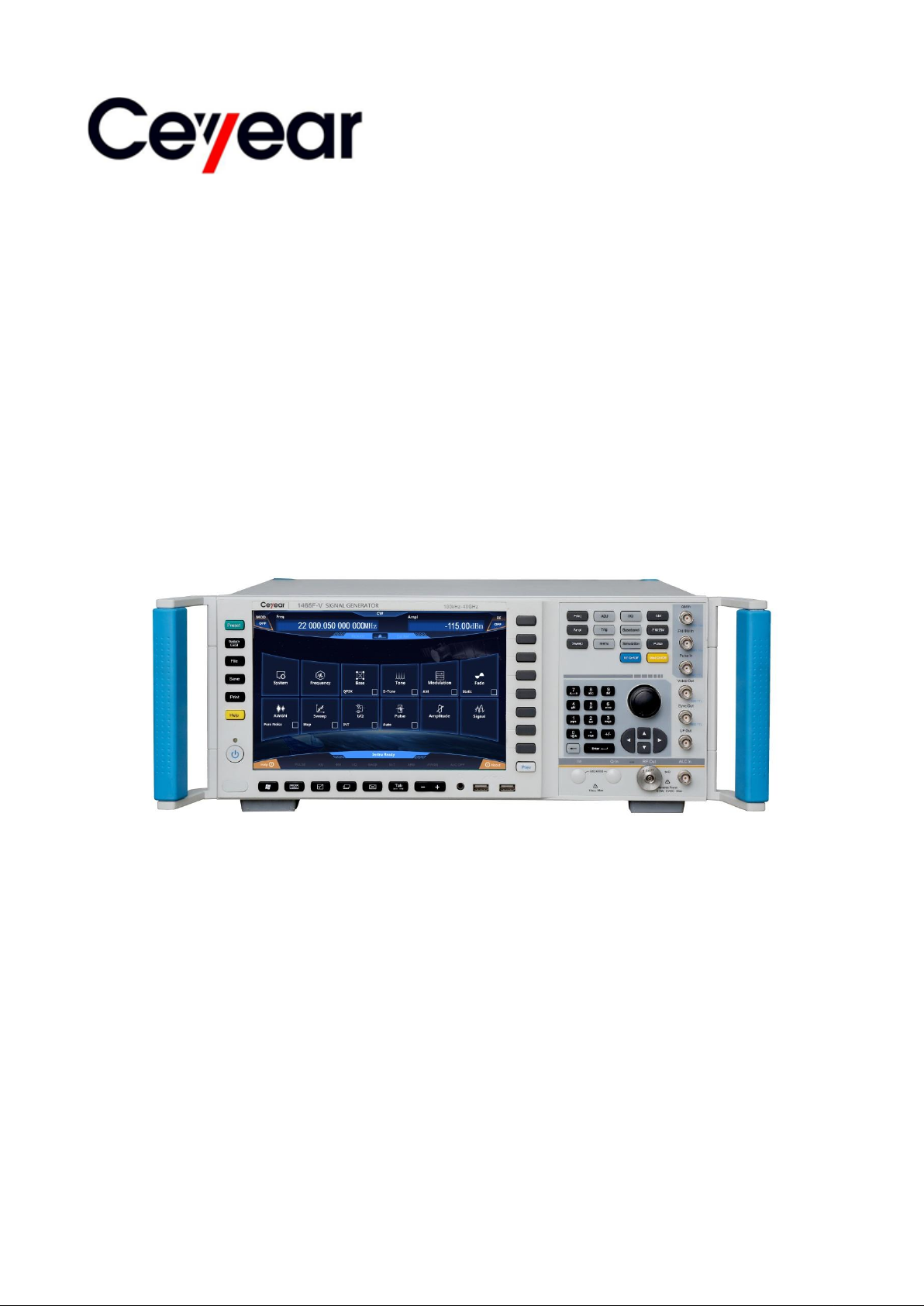
1465 Series
Signal Generator
Quick Start Guide
China Electronics Technology Instruments Co., Ltd
Page 2

This manual applies to the following types of signal generators, based on firmware version 1.0 and
above.
1465A Signal Generator (100kHz ~ 3GHz)
1465B Signal Generator (100kHz ~ 6GHz)
1465C Signal Generator (100kHz ~ 10GHz)
1465D Signal Generator (100kHz ~ 20GHz)
1465F Signal Generator (100kHz ~ 40GHz)
1465H Signal Generator (100kHz ~ 50GHz)
1465L Signal Generator (100kHz ~ 67GHz)
1465A-V Signal Generator (100kHz ~ 3GHz)
1465B-V Signal Generator (100kHz ~ 6GHz)
1465C-V Signal Generator (100kHz ~ 10GHz)
1465D-V Signal Generator (100kHz ~ 20GHz)
1465F-V Signal Generator (100kHz ~ 40GHz)
1465H-V Signal Generator (100kHz ~ 50GHz)
1465L-V Signal Generator (100kHz ~ 67GHz)
Edition: A.3 September 2018, China Electronic Technology Instruments Co., Ltd
Address: No. 98, Xiangjiang Road, Qingdao City, China
Tel.: (86) 0532-86896691
Web: www.ceyear.com
E-mail: [email protected]
Postcode: 266555
Page 3
Preface
Caution
Warning
Thank you very much for
choosing 1465 series signal
generator developed and
produced by China Electronics
Technology Instruments Co.,
Ltd. Our products, high-tech,
precise and sophisticated, are
highly cost effective among
similar products.
Pursuing to maximally meet
your demands, we will provide
you with quality measuring
instruments and first-class
after-sales services. Adhering
to our consistent tenet of "good
quality and considerate
service", we promise to provide
you with satisfactory products
and services.
Manual Number
2.827.1202 SKCN
Edition
Manual Authorization
The content of this manual is
subject to changes without
prior notice. The right of final
interpretation of the content
and terminology used in this
manual belongs to China
Electronic Technology
Instruments Co., Ltd.
The copyright of this manual
belongs to China Electronics
Technology Instruments Co.,
Ltd. Without authorization of
the company, no organization
or individual is allowed to
modify the content of this
manual or copy and
disseminate it for profit. China
Electronics Technology
Instruments Co., Ltd. reserves
the right to seek legal liabilities
of infringers.
required qualification and has
passed ISO 9001 and ISO
14001 management systems.
Safety Precautions
A Warning sign indicates the
existence of danger. It prompts
users to pay attention to a
certain operation process,
operation method or similar
situation. Failure to comply with
the rules or correct operation
may cause personal injury. Do
not proceed to the next step
after completely understanding
and meeting the warning
conditions.
A.3 2018.9
CHINA ELECTRONICS
TECHNOLOGY
INSTRUMENTS CO., LTD
Product Warranty
This product is under warranty
for 18 months from the date of
delivery. During the warranty
period, the manufacturer will
repair or replace the damaged
parts according to the actual
situation. Please refer to
related contracts for specific
maintenance and operation
matters.
Product Quality
Certification
We guarantee that this product
meets the specifications in the
manual as from the date it is
manufactured. The calibration
and measurement have been
completed by organizations of
metrology with national
qualifications, and relevant
information has been provided
for your reference.
Quality / Environmental
Management
This product has complied with
the quality and environmental
management systems in the
process of R&D, manufacturing
and testing. The company has
A Caution sign prompts some
important information, which
will not cause danger. It
prompts users to pay attention
to a certain operation process,
operation method or similar
situation. Failure to follow the
rules or operate correctly may
result in instrument damages or
loss of important data. Do not
proceed to the next step after
completely understanding and
meeting the conditions.
Page 4

Page 5

1465 Series Signal Generator
1
Contents
Contents
1 Manual Navigation ................................................................................................................................... 1
1.1 About the Manual .......................................................................................................................... 1
1.2 Related Documents ...................................................................................................................... 1
2 Getting Prepared ..................................................................................................................................... 3
2.1 Preparations before Operation ..................................................................................................... 3
2.2 Operating System Configuration ................................................................................................. 12
2.3 Appearance of Instrument........................................................................................................... 16
3 Typical Applications ............................................................................................................................... 21
3.1 Setting CW RF Output Frequency at 500 MHz and Power Level at 0 dBm ............................... 21
3.2 Generating AM Signals: LO Frequency of 3.5 GHz, Modulation Rate of 1 kHz, and AM Depth of
30%. .................................................................................................................................................. 24
3.3 Generating Pulse Modulation Signals: LO Frequency of 3.5 GHz, Pulse Width of 50 us, and
Period of 1 ms ................................................................................................................................... 26
3.4 Configuring Step Sweep: Start Frequency of 1 GHz, Stop Frequency of 3 GHz, and 5 Step
Points ................................................................................................................................................ 27
3.5 Configuring List Sweep: Start Frequency of 1 GHz, Stop Frequency of 3 GHz, and 5 List Points29
3.6 Configuring Ramp Sweep: Start Frequency of 1 GHz, Stop Frequency of 3 GHz .................... 31
3.7 Configuring Baseband: Data Source PN Sequence, Modulation Type QPSK, and Code Element
Rate of 4 Msps .................................................................................................................................. 32
3.8 Sequence Playback Function ..................................................................................................... 34
3.9 Arbitrary Wave Playback Function .............................................................................................. 36
3.10 Selecting ALC Bandwidth ......................................................................................................... 38
3.11 Setting Reset State ................................................................................................................... 39
3.12 Storing / Calling a User State ................................................................................................... 40
3.13 Copying / Moving / Deleting Files ............................................................................................. 42
4 Getting Help ........................................................................................................................................... 43
4.1 Basic Checks .............................................................................................................................. 43
4.2 Help Information .......................................................................................................................... 44
4.3 Repair .......................................................................................................................................... 45
Page 6

1465 Series Signal Generator
2
Contents
Page 7

1 Manual Navigation
1
1.1 About the Manual
1 Manual Navigation
This chapter introduces the function, chapters and main contents of the Quick Start Manual for 1465
Series Signal Generator, as well as instrument-related documents provided to users.
About the Manual ………………………………………………………………………………………1
Relevant Documents …………………………………………………………………………………1
1.1 About the Manual
This manual introduces the basic functions and operation methods of 1465 series signal generator.
It describes such information as the operations before startup, system settings, features of front and rear
panels, basic operation methods and examples, simple fault diagnosis and repair methods, so as to help
you get familiar with and master the operations and key points of this instrument as soon as possible. In
order to facilitate your proficiency in using the instrument, please read this manual carefully before
operating the instrument, and follow this manual for correct operation.
This Quick Start Manual contains the following chapters:
Getting Prepared
This chapter introduces such information as the pre-operation inspection, operating system
configuration, initialization configuration and appearance of 1465 series signal generator with the
purpose of helping users make early preparations for correct and safe operation of this instrument.
Typical Applications
This chapter gives a detailed description of the operation with examples, such as setting up RF CW
(continuous wave), modulation, sweep, data storage / calling, according to the frequency and
importance of the functions of the instrument so as to help users get familiar with the use of 1465 series
signal generator as soon as possible.
Getting Help
This chapter includes basic methods for fault diagnosis, solutions and repair of the instrument.
1.2 Related Documents
The product documentation of 1465 series signal generator includes:
Quick Start Manual
Online Help
User's Manual
Programmer’s Manual
Quick Start Manual
This manual introduces the configuration of the instrument and basic operations for startup
configuration with the purpose of allowing users to quickly understand the characteristics of the
instrument, master basic settings and basic local and programmable operations. It contains the following
chapters:
Getting Prepared
Typical Applications
Getting Help
User's Manual
This manual gives a detailed introduction of the functions and operations of the instrument,
including configuration, program control and maintenance information, with the purpose of instructing
users to comprehensively understand the features of the product and master common testing methods
Page 8

1 Manual Navigation
2
1.2 Related Documents
of the instrument. It mainly contains the following chapters:
Manual Navigation
Summary
Getting Started
Operation Guide
Menus
Remote control
Fault Diagnosis and Repair
Technical Indicators and Testing Methods
Appendixes
Programmer’s Manual
This manual gives a detailed introduction of programming foundation, SCPI foundation, SCPI
commands, programming examples and I / O driver function library with the purpose of instructing users
to quickly and comprehensively master the program control commands and methods of the instrument. It
mainly contains the following chapters:
Remote Control
Program Control Commands
Programming Examples
Error Description
Appendixes
Online Help
The online help is integrated into the instrument for providing quick help via text navigation so as to
facilitate the local and remote operations of users. Both the hard keys on the front panel or the toolbar in
the user interface provide shortcuts to activate this function. Its main chapters are the same as that of
the User’s Manual.
Page 9
2 Getting Prepared
3
Caution
Warning
2.1 Preparations before Operation
2 Getting Prepared
Preparations before Operation ………………………………………………………………………3
Operating System Configuration ……………………………………………………………………12
2.1 Preparations before Operation
This chapter introduces the precautions before setting and using the 1465 series vector signal
generator for the first time.
Unpacking ………………………………………………………………………………………………4
Instrument Placement and Installation ………………………………………………………………5
Power on / off ……………………………………………………………………………………………5
Correct Use of Connectors ……………………………………………………………………………7
User Check ……………………………………………………………………………………………9
Online Help ……………………………………………………………………………………………10
Avoid damaging the instrument
To avoid electric shock, fire and personal injury:
Do not open the chassis without authorization.
Do not attempt to disassemble or modify any part not specified in this manual. Disassembly
without permission may lead to decrease in the electromagnetic shielding efficiency and damage of
internal parts, which will affect the reliability of the product. If the product is under warranty, we will no
longer provide free maintenance.
Read carefully the section of "2.2 Safe Use Guide" of the User’s Manual and the following
operation safety precautions. Attention should also be paid to specific operating environment
requirements mentioned in the data pages.
Electrostatic protection
Please pay attention to the anti-static measures in the workplace to avoid damages to the
instrument. Please refer to the section "2.2 Safe Use Guide" of the manual for details.
Page 10
2 Getting Prepared
4
Caution
Tip
Caution
2.1 Preparations before Operation
When operating the instrument, please note:
Improper operating position or measurement settings may damage the instrument or instruments
connected to it. Please pay attention to the following before power-on of the instrument:
Ensure that the fan blades are not blocked, the radiator holes are unobstructed, and the
distance between the instrument and the wall is at least 10 cm.
Keep the instrument dry.
Place the instrument flat and reasonably.
The ambient temperature meets the requirements specified in the data pages.
The input signal power of the port meets the specified range.
The signal output port is connected correctly without overloading.
Influence of electromagnetic interference (EMI):
EMI will affect the measurement results, therefore:
Please select suitable shielded cables, double shielded RF / network connection cables, for
instance.
For opened cable connection ports, please close temporarily unused output ports or connect
matching loads to the ports in time.
Pay attention to refer to the EMC level specified in the reference data page.
2.1.1 Unpacking
2.1.1.1 Visual Examination
Step 1. Check the packing box and shock-proof package of the instrument for damages. If there are
no damages, keep the outer package for future use and proceed with the following steps.
Step 2. Unpack the instrument and check it and enclosed items for damages.
Step 3. Check the above items carefully according to Table 2.1.
Step 4. In case of any damages or mistakes of the packing box, the instrument and enclosed
articles, it is strictly forbidden to turn on the power! Please contact our Customer Service Center
according to the contact information provided in the inside front cover or "4.3 Repair", and we will repair
or replace it as soon as possible according to the actual situation.
Handling: Because the instrument and the packing box are heavy, they should be handled by two
people together with care.
Page 11
2 Getting Prepared
5
Name
Qty
Function
Generator:
1465
1
—
Standard:
Three-core power cord
1
User's Manual
1
—
Programmer’s Manual
1
—
Packing List
1
—
Product Qualification Certificate
1
—
Be Careful
2.1 Preparations before Operation
2.1.1.2 Model Confirmation
Table 2.1 List of enclosed items for 1465 signal generator
2.1.2 Instrument Placement and Installation
In order to ensure normal functionality of 1465 series signal generator, please note:
The operating site should meet: The operating environment requirements, heat dissipation
requirements, and correct electrostatic protection measures should be taken with reference to the
section "3.1.1.2 Environmental Requirements" in the User's Manual.
The operating requirements of a vertical instrument should be met: The instrument can be
placed horizontally on a worktable equipped with an anti-static table mat or supported by its own legs.
For details, please refer to the section "2.2.2 Operational Status and Location" in the User’s Manual.
Attention should be paid when deploying legs of the instrument:
To ensure instrument stability and personal safety, please fully deploy or retract the legs.
When the legs are deployed, do not move the instrument or operate or place articles under the
instrument.
In case of overload, the legs may break. When the legs are deployed, the maximum load shall
not exceed 500 N.
2.1.3 Power on / off
Methods and precautions for switching on / off the instrument are as follows:
2.1.3.1 Connecting Power Supply
Before the first power-on, please confirm the power supply parameters and the power cord. For
details, please refer to precautions before power-on in section 3.1.1.3 in the User’s Manual.
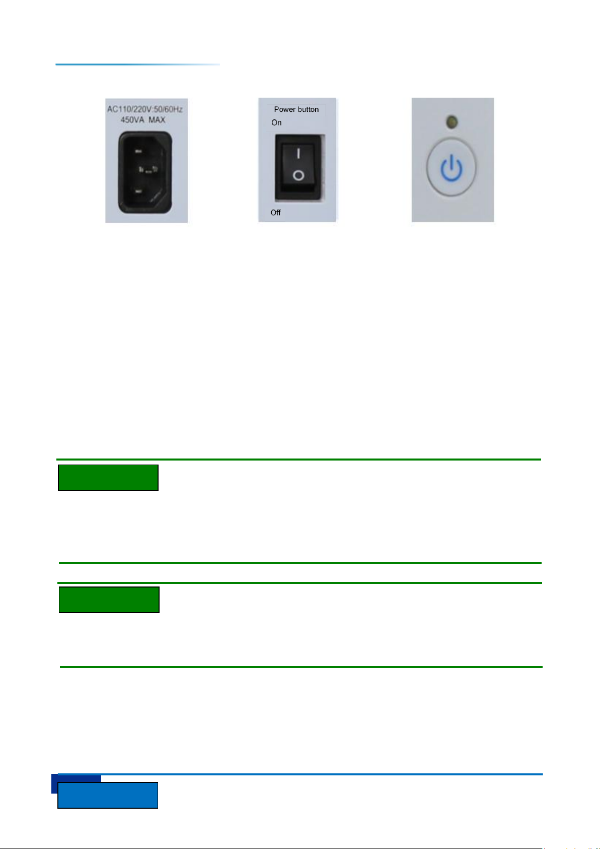
Step 1. Connect the power cord: Connect one end of the power cord delivered with the signal
generator in the packing box or a three-core power cord conforming to the requirements to the power
socket on the rear panel of the signal generator (Figure 2.1), and the other end to a conforming AC
power supply.
Step 2. Turn on the power switch on the rear panel: As shown in Figure 2.2, observe the standby
indicator above the front panel power switch (Figure 2.3) till it turns yellow.
Step 3. Turn on the power switch on the front panel: As shown in Figure 2.3, do not connect any
device to the signal generator before startup. If everything is normal, you can turn it on, and then the
indicator above the front panel power switch will turn green.
Page 12
2 Getting Prepared
6
Caution
Tip
Tip
2.1 Preparations before Operation
Figure 2.1 Power socket Figure 2.2 Rear panel power switch Figure 2.3 Front panel power switch
2.1.3.2 Turning on / off the Instrument
1) Turning on the instrument
Step 1. Turn on the back panel power switch ("|").
Step 2. Turn on the power switch in the lower left corner of the front panel (Figure 2.3), and then the
power indicator above the power switch will change from yellow to green.
Step 3. The user interface on the front panel of the signal generator will gradually display the
relevant information of the start-up process of the instrument: Firstly, the manufacturer's information is
briefly displayed, and then the operating system menu will be displayed. There are two options in the
menu, and users need not operate the menu during normal operation. Windows 7 will be started
automatically after the timer shows 0.
Step 4. After Windows 7 is started successfully, the system will automatically run the initialization
program of the signal generator and displays the main operation menu of the signal generator.
The instrument is now in an operational state.
10MHz Time Base and Preheating
In order to keep the 10 MHz time base of 1465 series signal generator at the operating temperature
during cold start, it is necessary to preheat it for a period of time. The signal generator does not need
time for preheating when it is started from the standby state. The instrument needs to be preheated for
two hours when testing indicators. (Refer to relevant instructions in the data indicators for details).
Attenuator Initialization
After entering the host program, when the attenuator is initialized, you will hear the sound of the
attenuator for setting ranges, so do not mistake it as an error of the signal generator.
Page 13
2 Getting Prepared
7
Caution
Be Careful
2.1 Preparations before Operation
System Startup
This instrument adopts the control platform of Windows + x86 computers. In the process of BIOS
self-test and Windows loading, no user intervention is required, so do not cut off the power halfway or
modify the settings in BIOS.
2) Turning off the instrument
Step 1. Turn off the power switch in the lower left corner of the front panel (Figure 2.3). At this time,
the instrument enters the shutdown process (some processing of the hardware and software is required
before the power can be turned off). After more than ten seconds, the instrument is powered off, when
the color of the power indicator above the power switch changes from green to yellow.
Step 2. Turn off the back panel power switch ("O") or disconnect the power of the instrument.
The instrument is now shut down.
Instrument Power Cut
During normal operation, the instrument can only be shut down by operating the front panel power
switch. Do not directly operate the back panel power switch or disconnect the power connection
with the instrument; otherwise, the instrument cannot enter the normal shutdown state, which will
damage the instrument or cause loss of the current instrument status / measurement data. Please
always shut down the instrument in the right way.
2.1.3.3 Cutting off the Power
Under abnormal circumstances, in order to avoid personal injury, emergency power cut of the signal
generator is necessary. At this point, you just need to unplug the power cord (from the AC socket or from
the power socket on the back panel of the instrument). Therefore, sufficient operating space should be
reserved when operating the instrument to allow you to directly cut off the power when necessary.
2.1.4 Correct Use of Connectors
Connectors are often used in various tests of the signal generator. Please pay attention to the
following precautions when using connectors:
2.1.4.1 Checking Connectors
Anti-static wristbands should be worn when checking connectors. A magnifier is recommended to
check the following:
1) Whether the electroplated surface is worn, and whether there are deep scratches.
2) Whether the thread is deformed.
3) Whether there are metal particles on the thread of the connector and the joint surface.
4) Whether the inner conductor is bent or broken.
5) Whether the bolt sleeve of the connector rotates badly.
Page 14
2 Getting Prepared
8
Keep still
Rotate the
screw sleeve
Keep still
2.1 Preparations before Operation
Avoid Damaging Instrument Ports through Connector Checking
Any damaged connector may damage the good connector connected to it even when during the first
measurement connection. In order to protect the various interfaces of the signal generator itself, it is
necessary to check the connectors before operating the connector.
2.1.4.2 Connection Method
Connectors should be checked and cleaned before measurement connection to ensure them to be
clean and free of damages. Anti-static wristbands should be worn during the connection. The correct
connection method and steps are as follows:
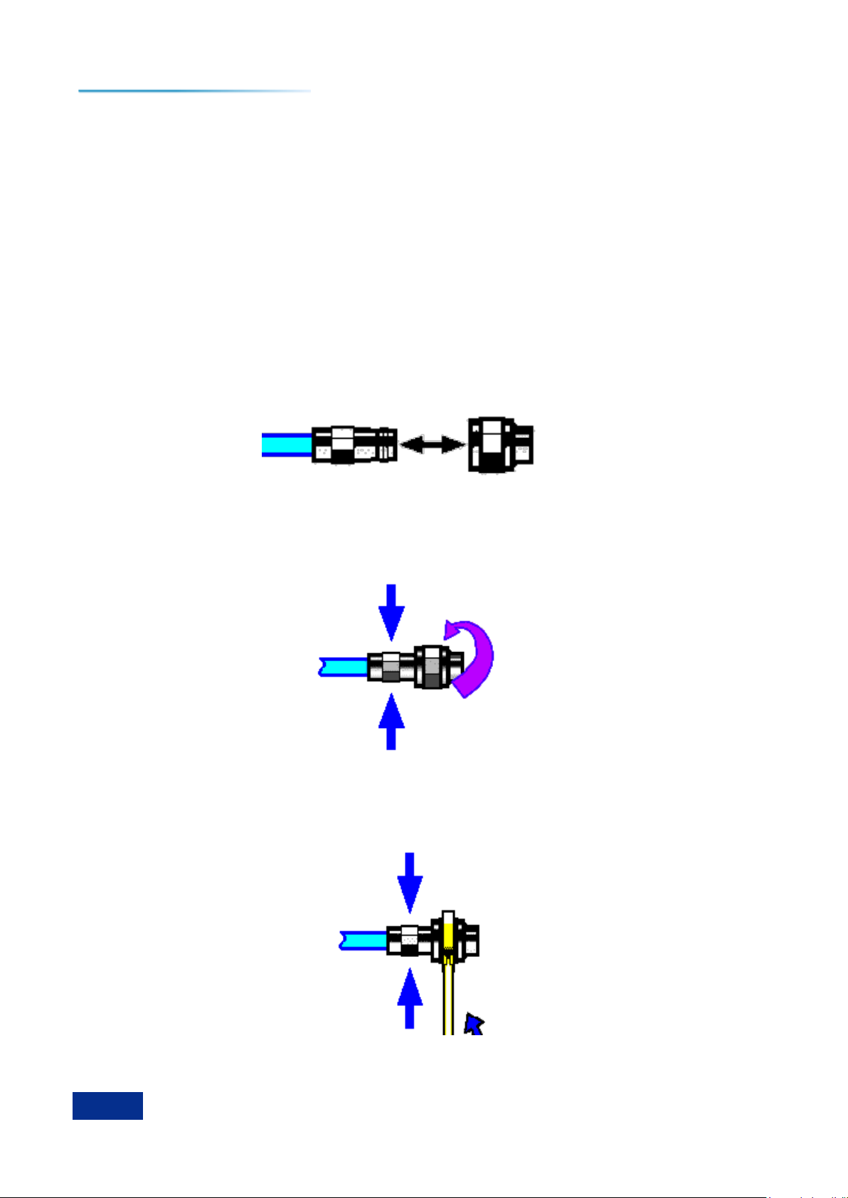
Step 1. As shown in Figure 2.4, align the axes of the two devices to be connected to ensure that the
pins of the male connector slide into the female connector concentrically.
Figure 2.4 The axes of the interconnected devices are along a straight line.
Step 2. As shown in Figure 2.5, move the two connectors horizontally together so that they can be
smoothly engaged. Rotate the connector bolt sleeves (not the connectors themselves) until tightened.
There should be no relative rotation between the connectors during the connection.
Figure 2.5 Connection method
Step 3. As shown in Figure 2.6, the connection is completed with a torque wrench. Attention should
be paid to prevent the torque wrench from exceeding the initial bending point. An auxiliary wrench can
be used to prevent the connectors from rotating.
Figure 2.6 Competing the connection with a torque wrench
Page 15
2 Getting Prepared
9
Torque direction
Stop applying force when the
handle is to be bent
Tip
2.1 Preparations before Operation
2.1.4.3 Disconnection Method
Step 1. Support the connectors to prevent any connector from being twisted, shaken or bent.
Step 2. An open-end wrench can be used to prevent the connectors from rotating.
Step 3. Loosen the bolt sleeves of the connectors with another wrench.
Step 4. Complete the disconnection by rotating the connector sleeves by hand.
Step 5. Pull the two connectors apart horizontally.
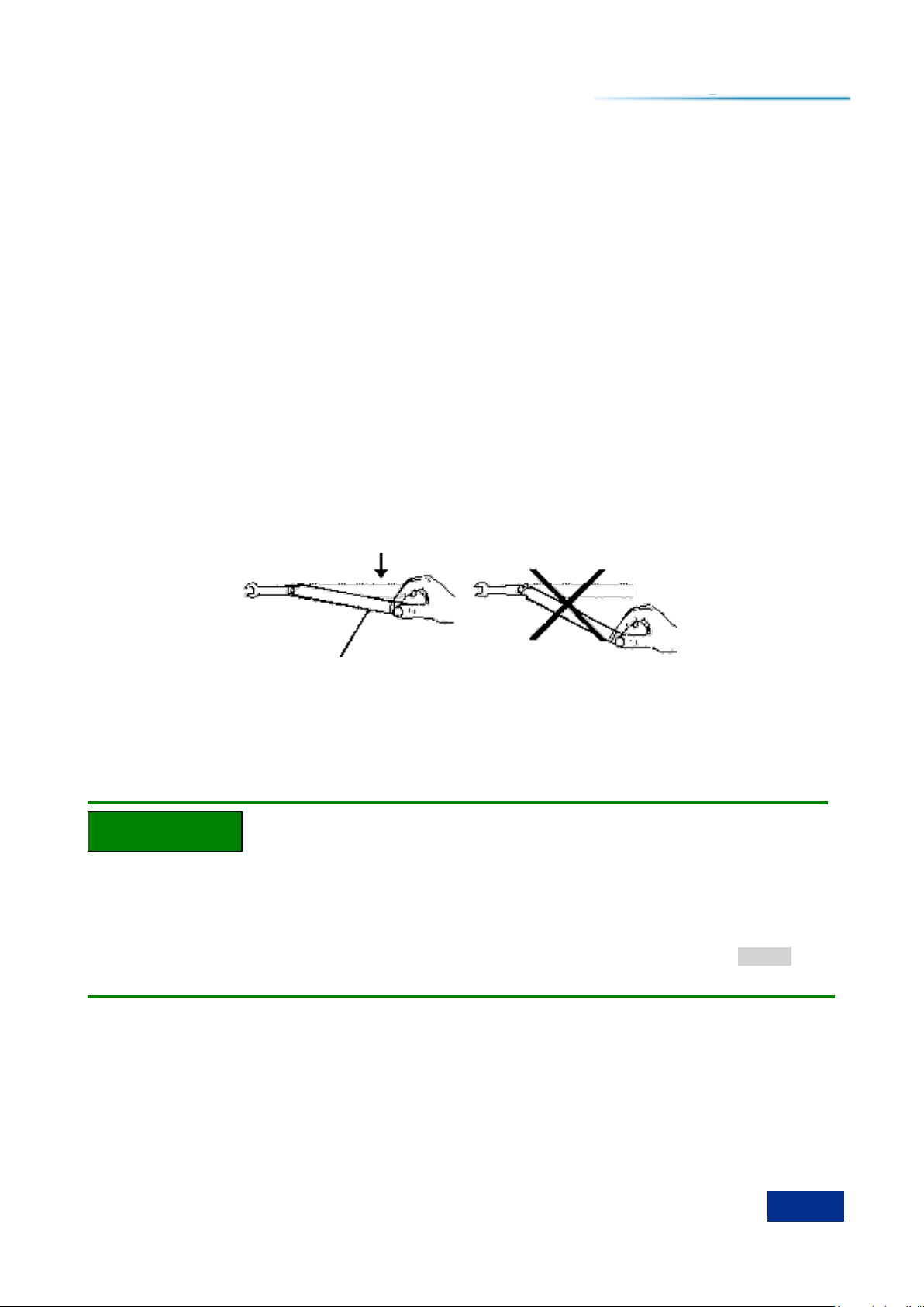
2.1.4.4 Use of Torque Wrenches
The use of a torque wrench is shown in Figure 2.7. The following points should be paid attention to
when using a torque wrench:
Make sure that the torque of the torque wrench is set correctly before use.
Make sure that the angle between the torque wrench and another wrench (used to support
connectors or cables) is within 90° before applying force.
Gently grasp the end of the torque wrench handle and apply a force in the direction
perpendicular to the handle until the breakout torque of the wrench is reached..
Figure 2.7 Use of a torque wrench
2.1.5 User Check
After the first power-on of 1465 series signal generator, it is necessary to check whether the
instrument works normally to ensure subsequent measurement.
Hard Keys on the Front Panel and Soft Keys in the Manu
The front panel keys are described as follows: [Frequency], where frequency is the name of the
hard key;
If a key corresponds to multiple states, the option of the selected value whose color changes and
the background is darkened indicates that the state is valid. For example: [Sweep Time Manual Auto]
indicates that the manual option of sweep time is valid.
2.1.5.1 Self-test
Connect the 1465 series signal generator to the power supply. Observe whether the power indicator
above the power switch in the lower left corner of the front panel is yellow, which indicates that the
standby power supply is working normally. Touch the front panel power switch and observe whether the
front panel power indicator turns green and the backlight of the display is on. The display start-up
process needs about 30 seconds, and then the boot status interface is displayed.
After 10 minutes of preheating, set the signal generator as follows:
Page 16

2 Getting Prepared
10
2.1 Preparations before Operation
Step 1. Press the [System] key on the front panel key or tap the [System] function area on the
touchscreen to enter the system menu.
Step 2. Select [self-test] in the self-test options.
Step 3. In the pop-up self-test configuration window, select the self-test project, select [Start Test],
and observe the test results: If successful, "all pass" will be displayed, indicating that the instrument
works normally; if failed, "Self-test failure, XX items failed" will be displayed, indicating that the
instrument is not working properly. In such case, please contact our Service Consultation Center
according to the contact information provided in the inside front cover or "4.3 Repair", and we will repair
or replace it as soon as possible according to the actual situation.
2.1.5.2 Function Verification
Turn on the 1465 series signal generator and preheat it for at least 30 minutes. The RF output
terminal is applied with matching load. Set the instrument as follows:
Step 1. Press the [Power] key on the front panel or tap the [Power] function area on the touch
screen to enter the power menu, and set the power at 0 dBm in the pop-up dialog box for power
parameter settings.
Step 2. Press the [Frequency] key on the front panel or tap the [Frequency] function area on the
touch screen to enter the power menu, and set the continuous wave at 100 MHz in the pop-up dialog box
for frequency parameter settings.
Step 3. Press the [FR On / Off] key on the front panel or tap the [FR] function area on the touch
screen to turn on RF output of the signal generator.
Step 4. Set the frequency of the signal generator up at the interval of 100 MHz with the arrow keys
on the front panel until the maximum frequency is reached. Pay attention to the alarm indication area of
the front panel display. If there is no alarm, it indicates that the instrument is working normally; If there is
any alarm information, it indicates that the instrument is not working properly. In this case, please contact
our Service Consultation Center according to the contact information provided in the inside front cover or
"4.3 Repair", and we will repair or replace it as soon as possible according to the actual situation.
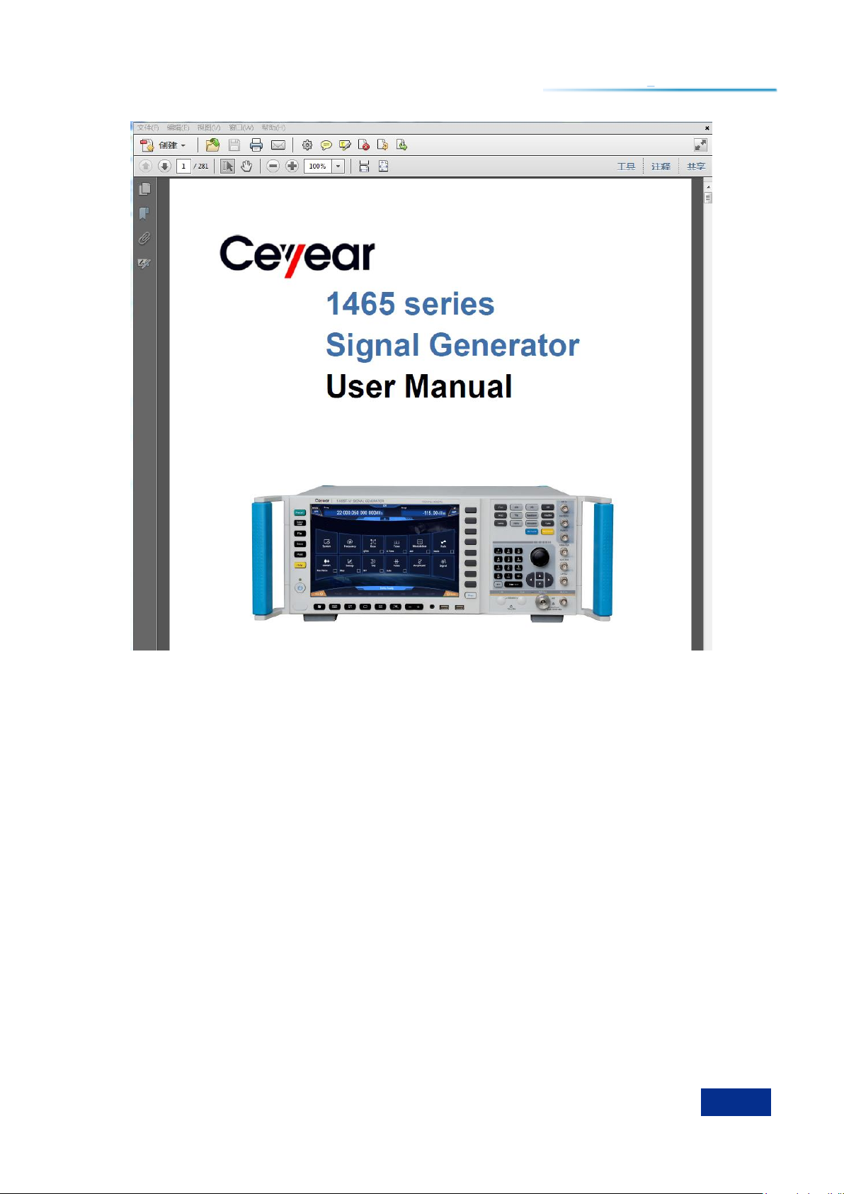
2.1.6 Online Help
The 1465 series signal generator offers online help feature. Press the yellow [Help] key on the left
side of the front panel to call the online help file "Help".
Page 17
2 Getting Prepared
11
2.1 Preparations before Operation
Figure 2.8 Opening 1465 online help file
Page 18
2 Getting Prepared
12
Caution
Caution
Caution
2.2 Operating System Configuration
2.2 Operating System Configuration
The 1465 series signal generator is equipped with Windows 7 operating system, which has been
configured according to the functions and requirements of the instrument. The host software of the
instrument is based on Windows 7 operating system, which has been installed before shipment of the
instrument. To ensure normal operation of the instrument software, certain rules must be obeyed when
using the operating system.
Windows 7 Configuration ……………………………………………………………………………12
Windows 7 System Security and Maintenance ……………………………………………………14
Third-party Software Affects Instrument Performance
The 1465 series signal generator adopts the open Windows environment. Installing other third-party
software may affect the performance of the signal generator. Please use only software that has been
tested by the manufacturer and is compatible with the host software.
2.2.1 Windows 7 Configuration
The operating system of 1465 series signal generator has been configured to the best state before
shipment of the instrument. Any change of the operating system settings may cause decline in the
measurement performance of the instrument. Normally, you need not make any changes to settings of
the Windows operating system.
BIOS Settings are not Modifiable
Users should not modify the settings in BIOS; otherwise, the instrument may be subject to
exceptions in startup and operation.
Changing System Configuration Causes Problems
In case of problem in the use of the instrument or system crashes due to change in the system
configuration, the system recovery tool of the instrument can be used to recover the operating system
and the application software. You can also contact our Service Consulting Center by dialing our service
number provided in this manual, and we will solve your problems as soon as possible.
However, in order to facilitate users in measurement reports and system integration, the following
items can be changed by users as required.
Configuring GPIB ……………………………………………………………………………………12
Configuring LAN ………………………………………………………………………………………13
2.2.1.1 Configure GPIB
Users may need to modify the GPIB address when using the signal generator to build the system.
Page 19
2 Getting Prepared
13
2.2 Operating System Configuration
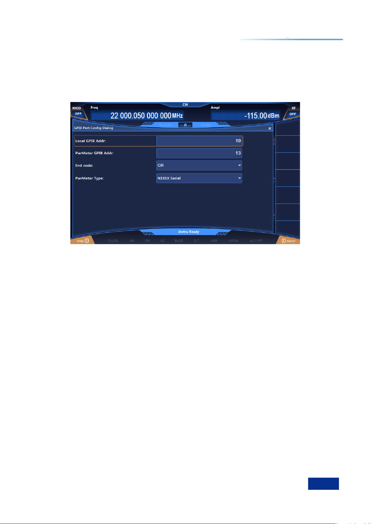
The default GPIB address of the local machine is 19.
The GPIB address can be change as follows:
Press the [System] key on the front panel or tap the [System] function area on the touch screen and
select [GPIB Interface] to enter the interface shown in Figure 2.9, where you can change the address in
the GPIB address bar with numeric keys on the front panel or by tapping on the touch screen.
Figure 2.9 GPIB port settings
2.2.1.2 Configuration LAN
a) Change host name
The host name (computer name) of 1465 series signal generator has been preset as "41-PC" before
leaving the factory. In order to avoid the repeated names in the network, for such cases as multiple 1465
signal generators are connected in the same network, users may change the host names as required.
The specific steps to change the host name are as follows: (or you can refer to Help Document of
Microsoft Windows 7.)
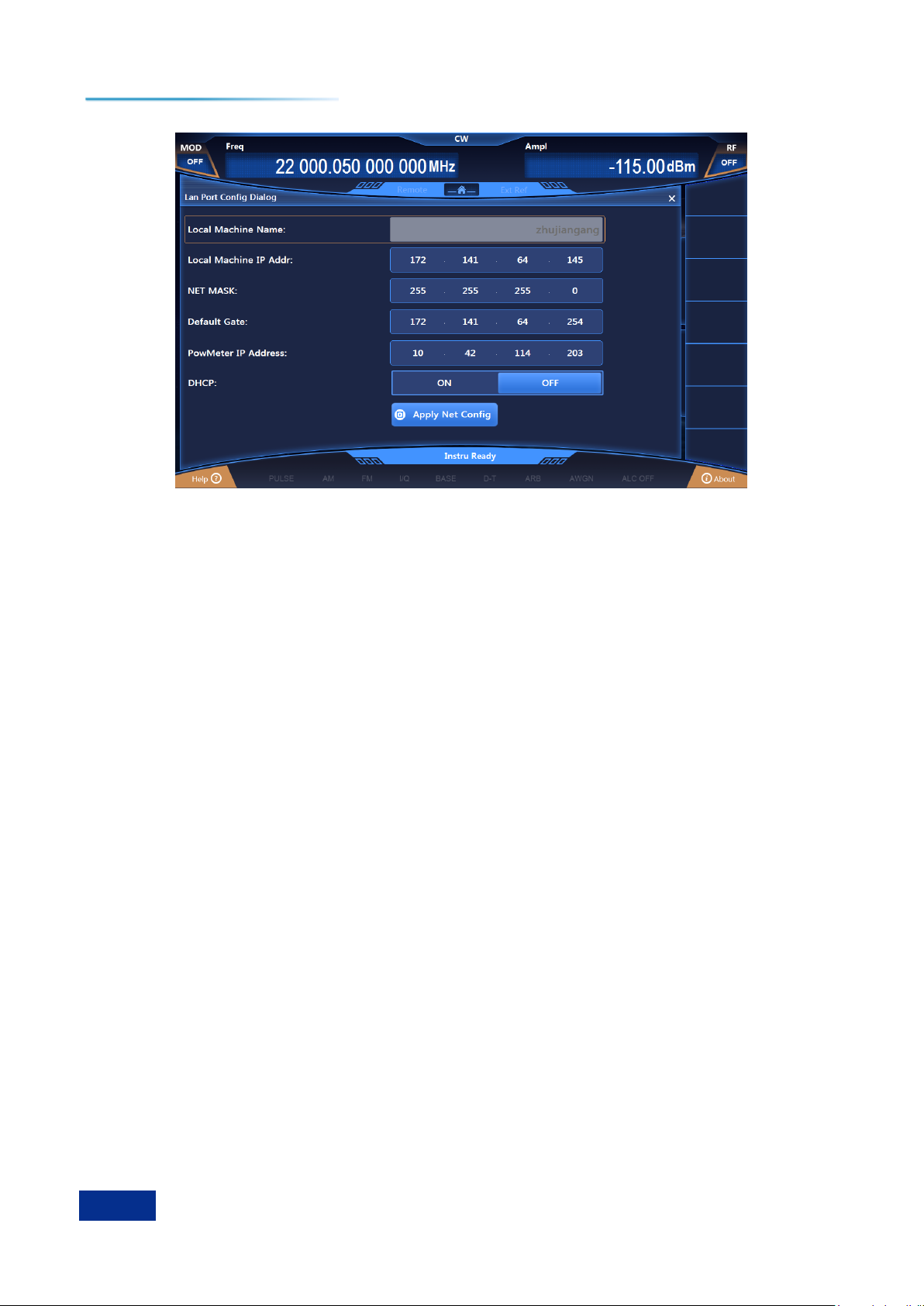
Step 1. Press the [System] key or tap the [System] function are and select "LAN Interface" to enter
the network property settings page as shown in Figure 2.10, which displays the "Host Name" in the
current LAN.
Step 2. Edit and type in the new host name, and close the current dialog box.
Page 20
2 Getting Prepared
14
2.2 Operating System Configuration
Figure 2.10 Lan port configuration
b) Configure IP address, subnet mask, and default gateway
The IP address and gateway are so preset as to automatically obtain IP address before shipment of
the instrument. IP address, subnet mask, and gateway can be changed manually. In the window shown
in Figure 3.10, you can change the IP address, subnet mask and default gateway. For detailed
operations, please refer to the steps in "a) Changing host name" or refer to the Help Document of
Microsoft Windows 7.
c) Change system firewall settings
The firewall is used to prevent unauthorized users from remotely operating the instrument.
Therefore, we suggest that you enable the firewall protection. The firewall protection for all port
connections of the system related to remote operations has been enabled before shipment of the 1465
series signal generator.
The Administrator has the only permission to change firewall settings.
2.2.2 Windows 7 System Security and Maintenance
2.2.2.1 Antivirus Software
Installation of antivirus software may have some negative effects on the performance of the
instrument. To avoid virus infection, users are strongly recommended not to use the instrument as a
normal computer for browsing web pages or transferring files.
Before using any USB mobile storage devices, it is firstly required to carry out anti-virus processing
on such mobile devices based on a computer installed with the latest antivirus software to prevent the
devices from become virus carriers.
Once the signal generator system platform is infected with virus, it will have a negative impact on its
operation and use. In such cases, system recovery operation is recommended. Refer to the relevant
content in "2.2.2.2 System Maintenance" of this section for details on system recovery operation.
2.2.2.2 System Maintenance
1) Windows 7 Backup
Users are recommended to make system backups regularly. The data and system of the instrument
can be backed up completely with the "System Recovery Tool" of this instrument. For detailed operation,
please refer to "System Backup and Recovery".
It is recommended that in order to make backups of the instrument before it can be used for
Page 21

2 Getting Prepared
15
2.2 Operating System Configuration
purposes other than conventional use, such as long-term access to the Internet, installation of third-party
software, to avoid accidental infection of viruses and other harmful operations to the instrument system.
The Windows 7 operating system also offers the function of data backup, which can be used to back
up all data on the instrument and create system disks that can be used to restore Windows in case of
serious failure. More information can be obtained from the Help and References of Windows 7. You can
also use third-party backup software provided that it does not conflict with the system software of the
instrument. It is recommended that the system data be backed up on external devices, such as only hard
drives or USB hard drives.
2) Windows 7 System Recovery
Windows 7 has the function of system recovery, which can restore the system to its previous state.
However, the built-in system backup and recovery function of Windows is not always successful, so this
solution is not recommended. For specific recovery steps, please refer to the section "3.1.2.5 System
Backup and Recovery" in the User’s Manual.
2.2.2.3 Hard Drive Partitioning and Use
The hard drive is divided into three partitions: "Local Disk C:", "Local Disk D:" and "Local Disk E:".
Disk C is a system disk with Windows 7 operating system.
Disk D stores instrument applications and data. Third-party software can also be installed on Disk D.
D is the only drive letter for backup and recovery.
Disk E is mainly used for data backup storage, including system data on Disk C, instrument data on
Disc D and software data stored by users. The backup data on Disk E can be copied to external storage
media so that users will only need to restore the backup data to a new hard drive even if it is required to
replace the hard drive.
Page 22
2 Getting Prepared
16
SN
Name
Description
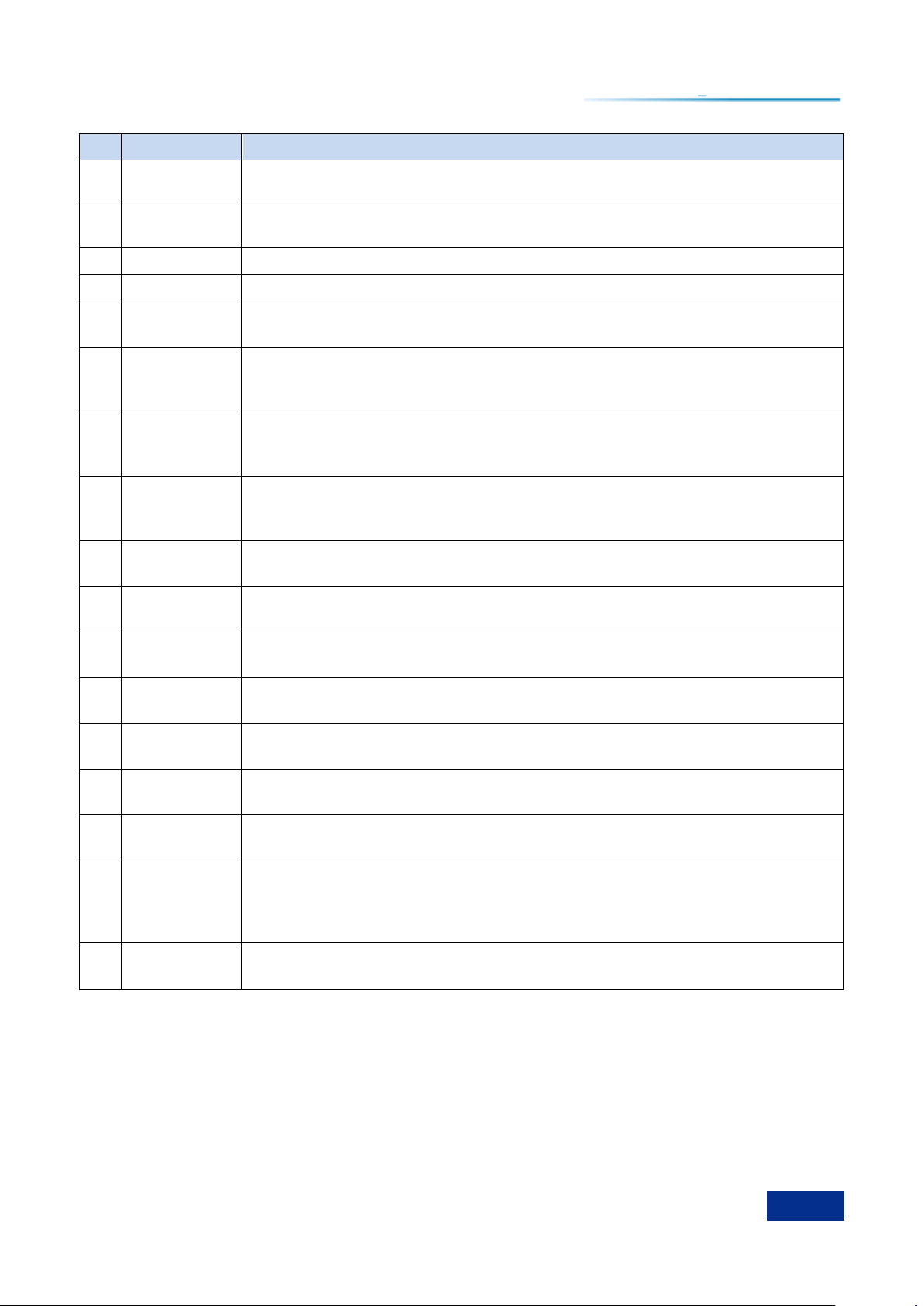
1
Display area
LED display, used to display all measurement results, states and settings
information, and allow switching between different measurement tasks. Refer to
Chapter ―3.3.1.1 Characteristics of the Operation Interface‖ for details.
2
Soft key area
When a soft key is pressed, the display area will display the menu name directly
corresponding to the left side of the soft key. Selecting a soft key is equivalent to
selecting the adjacent menu item.
3
Function area
It is composed of function hard keys of the front panel. Selecting the keys allows
you to execute such functions of the instrument as frequency, power, sweep,
2.2 Operating System Configuration
2.3 Appearance of Instrument
This chapter introduces the elements of the front and rear panels and operation interfaces of 1465
series signal generator, their functions, as well as composition and functions of the front panel.
Front Panel ……………………………………………………………………………………………16
Operating Interface ……………………………………………………………………………………17
Rear Panel ……………………………………………………………………………………………18
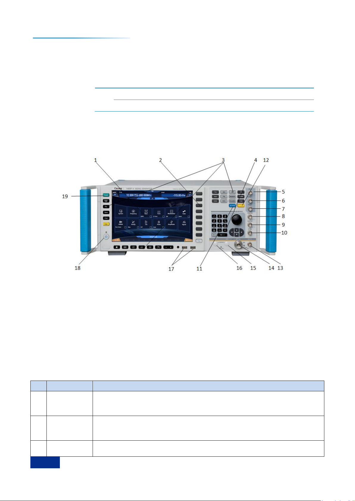
2.3.1 Front Panel
This section introduces the composition and functions of the front panel of 1465 series signal
generator. The front panel is as shown below (Figure 2.11) and detailed description is provided in Table
2.2.
1. Display area
2. Soft key area
3. Function area
4. Input area
5. AM
6. FM / ΦM input
7. Pulse input
Figure 2.11 Front panel of1465
8. Monitor output
9. Synchronous output
10. Low frequency output
11. RF switch
12. Modulation switch
13. External detector input
14. RF output
Table 2.2 Front panel description
15. Q input
16. I input
17. USB interface
18. Power switch
19. Reset key
Page 23
2 Getting Prepared
17
SN
Name
Description
modulation, baseband mode, I / Q, arbitrary wave, calibration, display, triggering,
confirmation, exit, menu, system, storage calling, file, printing, reset and local.
4
Input area
It contains arrow keys, knobs, ←/– (backspace / negative sign), and numeric
keys. All inputs can be changed with keys and knobs in the input area.
5
AM input
BNC female, input fixed at ±1Vp, achieving external AM function.
6
FM / ΦM input
BNC female, input fixed at ±1Vp, achieving external FM / PM function.
7
Pulse input
BNC female, compatible with TTL level pulse signal input signal, input impedance
2 kΩ.
8
Monitor output
BNC female, outputting pulse signal compatible with TTL, outputting pulse signals
consistent with modulation envelope in all pulse modes, with rated source
impedance at 50 Ω.
9
Synchronous
output
BNC pupil, outputting a synchronous pulse signal with the rated width of 20 ns in
internal and triggered pulse modulation process and compatible with TTL, with
rated source impedance at 50 Ω.
10
Low
frequency
output
BNC female, capable of outputting low frequency signals with frequency of 0.01
Hz - 10 MHz, amplitude of 40 mVp - 4 Vp and output impedance of 50 Ω through
settings.
11
RF switch
Turning on / off the RF output. When it works, the green indicator on its right side
will be one, indicating that the RF is enabled; otherwise, RF is disabled.
12
Modulation
switch
Enabling / disabling the modulation function, allowing users to set corresponding
modulation parameters as needed in the modulation window.
13
External
detector input
BNC female, providing users with amplitude stabilization control function.
14
RF output
The output of the signal generator, with the output impedance of 50 Ω and the
reverse power of 0.5 W.
15
Q input
BNC female, receiving I / Q modulated "Q" inputs, with input impedance of 50 or
600 Ω.
16
I input
BNC female, receiving I / Q modulated "I" inputs, with input impedance of 50 or
600 Ω.
17
USB interface
Used for connection of mice and keyboards for upgrading system software and
backup data, etc..
18
Power switch
When the instrument is in the "Standby" state, the yellow indicator on the left side
above the power switch is on; when the power switch is pressed once, the green
indicator on the upper right side of it is on, indicating that the instrument is in the
"Working" state.
19
Reset key
Click the key to restart the instrument, and enter the factory or user settings state
after self-test and initialization of the system.
2.3 Appearance of Instrument
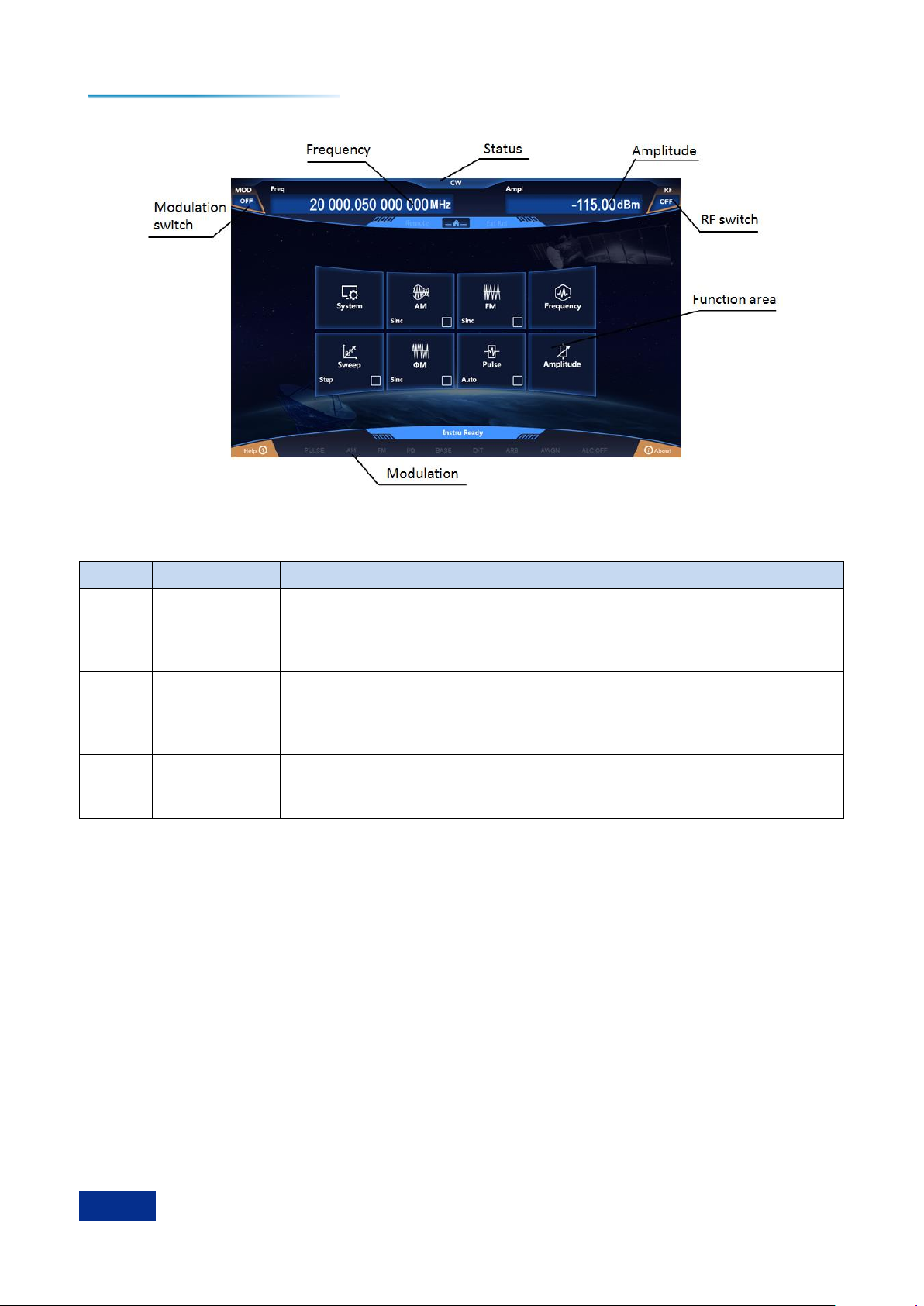
2.3.2 Operating Interface
The LED display on the front panel of 1465 series signal generator is used to display user's
operation interface, where the status of all measurement tasks, parameter settings and measurement
results are displayed. Please refer to Figure 2.12 and detailed description in Table 2.2.
Page 24
2 Getting Prepared
18
SN
Name
Description
1
Main
information
area
Displaying the main parameter values: Frequency, power, modulation switch
state, radio frequency switch state and modulation state, etc., corresponding
to frequency display, power display, modulation switch and RF switch in
Figure 2.12.
2
Function area
When corresponding functions are selected by tapping in the function area
of the display or pressing the front panel function keys, corresponding
menus will be displayed in this area. This area corresponds to the function
area in Figure 2.12.
3
Status
indicator area
It is used to display the working mode, working state and the latest warning /
error information of the instrument. This area corresponds to state indication
and modulation indication in Figure 2.12.
2.3 Appearance of Instrument
Figure 2.12 Operating Interface of 1465
Table 2.3 Operating interface description
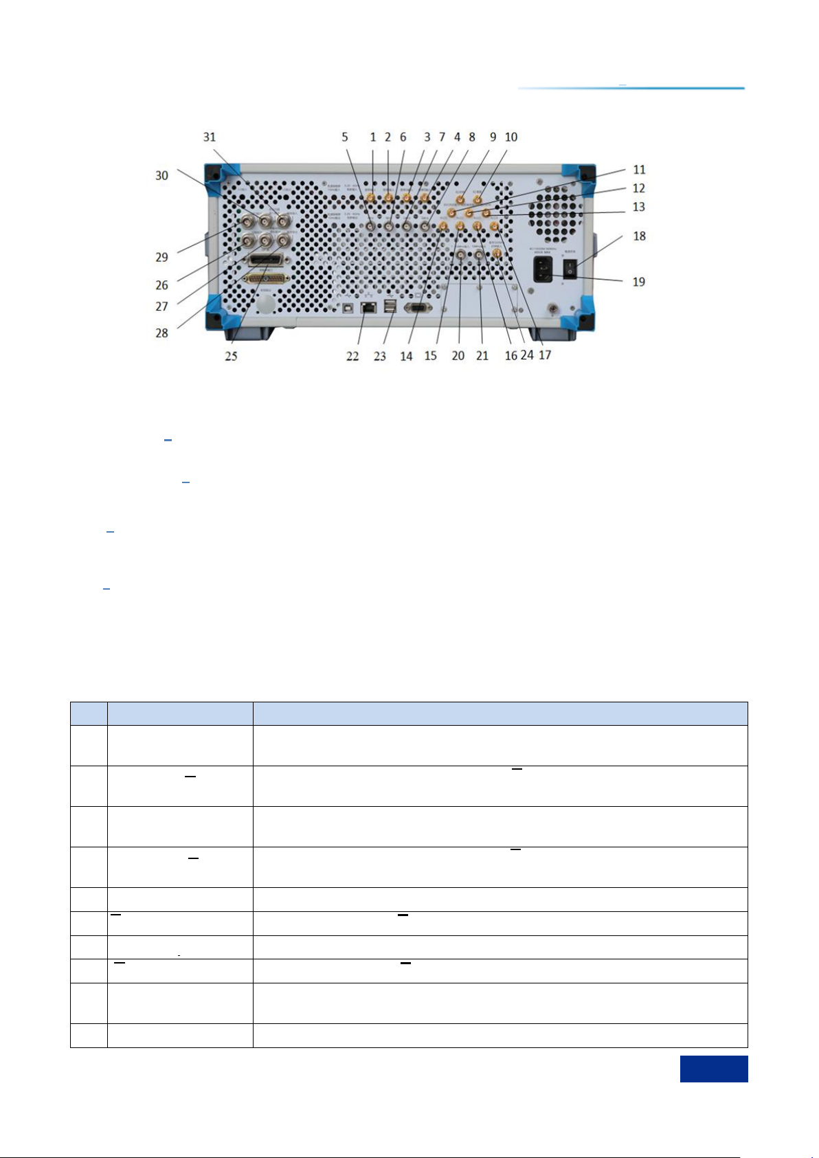
2.3.3 Rear Panel
This section introduces the composition and functions of the rear panel of 1465 series signal
generator. The rear panel is as shown below (Figure 2.13) and detailed description is provided in Table
2.4.
Page 25
19
Figure 2.13 Rear panel of 1465
SN
Name
Description
1
I Input
SMA female, external baseband signal I input when external broadband is
selected for IQ modulation.
2
Broadband I Input
SMA female, external baseband signal I input when external broadband is
selected for IQ modulation.
3
Broadband Q-input
SMA female, external baseband signal Q input when external broadband is
selected for IQ modulation.
4
Broadband Q-input
SMA female, external baseband signal Q input when external broadband is
selected for IQ modulation.
5
I output
BNC female, channel I output of internal baseband signal generator.
6
I output
BNC female, channel I output of internal baseband signal generator.
7
Q output
BNC female, channel Q output of internal baseband signal generator.
8
Q output
BNC female, channel Q output of internal baseband signal generator.
9
IQ clock
SMA female, when the data source is external in the baseband mode, IQ
serial clock input, with the level compatible with 3.3V-LVTTL.
10
IQ data
SMA female, when the data source is external in the baseband mode, IQ
2 Getting Prepared
2.3 Appearance of Instrument
1. Broadband I Input
2. Broadband I Input
3. Broadband Q-input
4. Broadband Q-input
5. I output
6. I output
7. Q output
8. Q output
9. IQ clock
10. IQ data
11. Trigger input
12. Code pattern trigger input
13. Code element clock
14. Marker 1
15. Marker 2
16. Marker 3
17. Marker 4
18. Power switch
19. Power input
20. 1 - 50 MHz input
21. 10 MHz output
22. LAN
Table 2.4 Rear panel description
23. USB
24. Baseband 500 MHz clock
input
25. GPIB
26. Sweep output
27. Z-axis blanking / frequency
standard output
28. Trigger output
29. Flyback output
30. Stop sweep input / output
31. Trigger input
Page 26
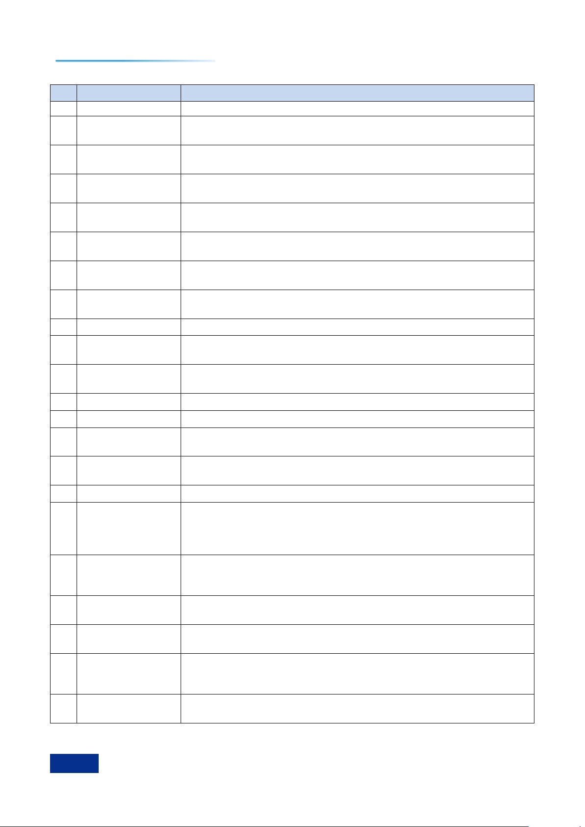
2 Getting Prepared
20
SN
Name
Description
serial data input, with the level compatible with 3.3V-LVTTL.
11
Trigger input
SMA female, external trigger signal input in baseband and arbitrary wave
mode, with the level compatible with 3.3V-LVTTL.
12
Code pattern trigger
input
SMA female, external code pattern trigger input in baseband and arbitrary
wave mode, with the level compatible with 3.3V-LVTTL.
13
Code element clock
SMA female, code element clock input in the baseband mode when the
data source is external, with the level compatible with 3.3V-LVTTL.
14
Marker 1
SMA female, outputting marker 1 set by arbitrary wave in arbitrary wave
modulation.
15
Marker 2
SMA female, outputting marker 2 set by arbitrary wave in arbitrary wave
modulation.
16
Marker 3
SMA female, outputting marker 3 set by arbitrary wave in arbitrary wave
modulation.
17
Marker 4
SMA female, outputting marker 4 set by arbitrary wave in arbitrary wave
modulation.
18
Power switch
Control switch of the main power of the instrument.
19
Power input
power plug of the instrument, parameter requirements: 220 V (+10%), 50
Hz (+5%), 200 W.
20
1-50 MHz input
BNC female, receiving frequency reference signals with 1 - 50 MHz, step of
1 Hz and -5 ~+10 dBm from the external time base.
21
10 MHz output
BNC female, signal level >+4 dBm, typical output impedance of 50 Ω.
22
LAN
Used for software upgrading and control, etc..
23
USB
Used for mouse and keyboard connection, system upgrading and data
backup, etc..
24
Baseband 500 MHz
clock input
SMA female, used for external clock input when external input is selected
for the baseband clock.
25
GPIB
Standard IEEE488 interface, supporting SCPI language.
26
Sweep output
BNC female, outputting voltage in direct proportion of the sweep frequency,
0 V corresponding to the start frequency of the sweep, and 10 V
corresponding to the stop frequency of the sweep (0 - 10 V corresponding
to the frequency range of the whole instrument in CW mode).
27
Z-axis blanking /
frequency standard
output
BNC female, outputting positive pulse (+5V for load of 2kΩ) during flyback
of RF output or band switching; outputting negative pulse (-5V) for RF
output = activated frequency scale frequency..
28
Trigger output
In the frequency sweep mode, it corresponds to the output of TTL low
pulses with the width of 1 μs for each frequency conversion.
29
Flyback output
Outputting TTL high level when the frequency sweep starts and outputting
TTL low level upon completion of the frequency sweep.
30
Stop Sweep input /
output
BNC female, outputting TTL high level when the frequency sweep starts
and outputting TTL low level upon completion of the frequency sweep. If
externally grounding, it can force the instrument to stop frequency sweep.
31
Trigger input
BNC female, valid on the TTL rising edge, used for frequency hopping in
external trigger stepping and list sweep modes.
2.3 Appearance of Instrument
Page 27
3 Typical Applications
21
Tip
Tip
3.1 Setting CW RF Output Frequency at 500 MHz and Power Level at 0 dBm
3 Typical Applications
This section introduces common and important basic settings and functions of 1465 series signal
generator step by step through examples with the purpose of enabling users to quickly understand the
characteristics of the instrument and master the basic measurement methods.
Firstly, the signal generator completes the preparatory work before the operation in the following
steps:
Step 1. Power-on.
Step 2. Initialization after entering the system.
Step 3. Preheating for 10 minutes.
Step 4. When there’re no error message prompts in the main interface of the front panel, proceed
with the following operations.
The basic settings mainly include: Setting and output of the continuous wave RF signal, as well as
the setting and output of the modulation signals through the user interface on the front panel of the signal
generator. According to the following steps, the RF output port of the front panel of the signal generator
can be used to output corresponding RF signals, and the system configuration window can be used to
save user status.
Step 1. Set the frequency and power parameters of continuous wave RF signals.
Step 2. Set carrier modulation parameters.
Step 3. Store user status.
Front Panel Keys and Mouse Operation are both Supported
The user interface of the 1465 series signal generator supports operation with keys on the front
panel, the touch screen and mouse. The following examples mainly show operation with keys on the
front panel. The operation with keys on the front panel corresponds to menu operation with the touch
screen and a mouse.
User may also complete the same operations through the touch screen of the instrument or a
mouse as required.
3.1 Setting CW RF Output Frequency at 500 MHz and Power Level at 0 dBm
Instrument Reset State
The reset state of the signal generator can be set to one specified by the user as required. However,
in the following example, the factory-specified reset state is used. The reset state of the instrument can
be changed in the setting of [System]. Before performing the following operations, please confirm that
the current reset status is [Factory].
Step 1. Reset.
Press the [Reset] key to set the signal generator to the factory-specified state.
Step 2. RF on.
Page 28
3 Typical Applications
22
3.1 Setting CW RF Output Frequency at 500 MHz and Power Level at 0 dBm
Press the [RF ON / OFF] key or tap the [RF] function area on the touch screen to switch to RF
for output of RF signals.
At this time, the RF switch state area in the operation interface of the front panel displays "RF ON".
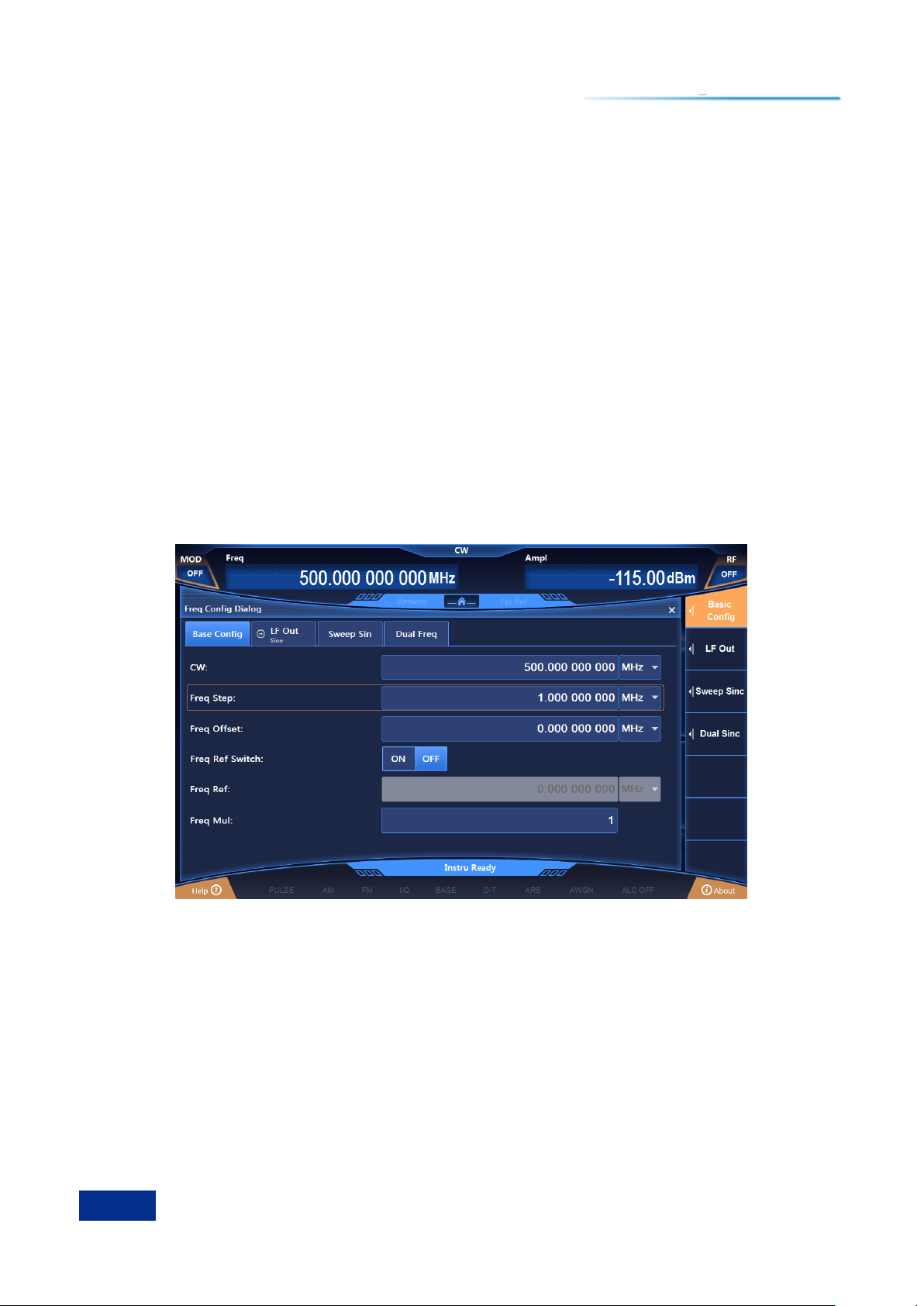
Step 3. Set CW at 500 MHz and frequency step to 1 MHz.
Press [Frequency] to edit the frequency.
Press the [Frequency] key or tap the [Frequency] function area on the touch screen, and the
frequency configuration window will pop up.
Rotate the front panel RPG clockwise (or counter-clockwise), select the frequency input box, and
press the knob, when the frequency input box is in the editing state; or tap the frequency input box on the
touch screen to make the frequency input box in the editing state. The frequency value displayed in the
current editing box is the default value of the system or the frequency value set in the previous CW
operation. At this time, type 500 MHz to end the input, and the display frequency of the main information
display area will be refreshed synchronously.
Edit frequency stepping.
Rotate the front panel RPG clockwise (or counter-clockwise) to select the frequency stepping
editing box in frequency settings; or tap the frequency stepping editing box on the touch screen to make
the box in the editing state. Similar to the method of setting point frequency, set the frequency stepping
value to 1 MHz.
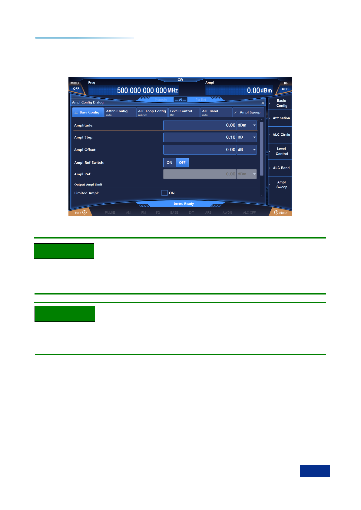
Figure 3.1 Setting CW to 500 MHz and frequency stepping value to 1 MHz
Step 4. Set the power to 0 dBm and step to 0.1 dB:
Edit power
Press the [Power] key or tap the [Power] function area on the touch screen, and the power
configuration window will pop up (Figure 3.2).
Rotate the front panel RPG clockwise (or counter-clockwise) to select the power input box, press
the knob, and the power input box is in the editing state; or tap the power input box on the touch screen
to make the power input box in the editing state. The current display of power value is the default value
of the system or the power value set in the previous power level operation. Enter 0dBm in the box to end
the input. The power displayed in the main information display area will be refreshed synchronously.
Edit power step
Rotate the front panel RPG clockwise (or counter-clockwise) to select the power step editing box in
Page 29
3 Typical Applications
23
Tip
Tip
3.1 Setting CW RF Output Frequency at 500 MHz and Power Level at 0 dBm
power settings; or tap the power step editing box on the touch screen to make the power step editing box
in the editing state, then set the power step value to 0.1 dB in the method similar to setting the
frequency.
Figure 3.2 Setting power level to 0 dBm and power step to 0.1dB
Focus Sequence in the CW / Power Input Box
To facilitate user input, when the frequency / power configuration window is opened, the CW /
Power input box is automatically in the editing state.
Changing Input Box Parameter by Stepping
When the input box is in the editing state, you can change the input parameters by stepping through
the front panel RPG or the arrow keys.
Page 30

3 Typical Applications
24
3.2 Generating AM Signals: LO Frequency of 3.5 GHz, Modulation Rate of 1 kHz, and AM Depth of 30%.
3.2 Generating AM Signals: LO Frequency of 3.5 GHz, Modulation Rate of 1 kHz, and
AM Depth of 30%.
The 1465 series signal generator has four modulation functions: AM, FM, phase modulation and
pulse modulation.
Step 1. Set RF output signals of the signal generator:
Set CW to 3.5 GHz and power level to 0 dBm.
Step 2. Activate the AM configuration window:
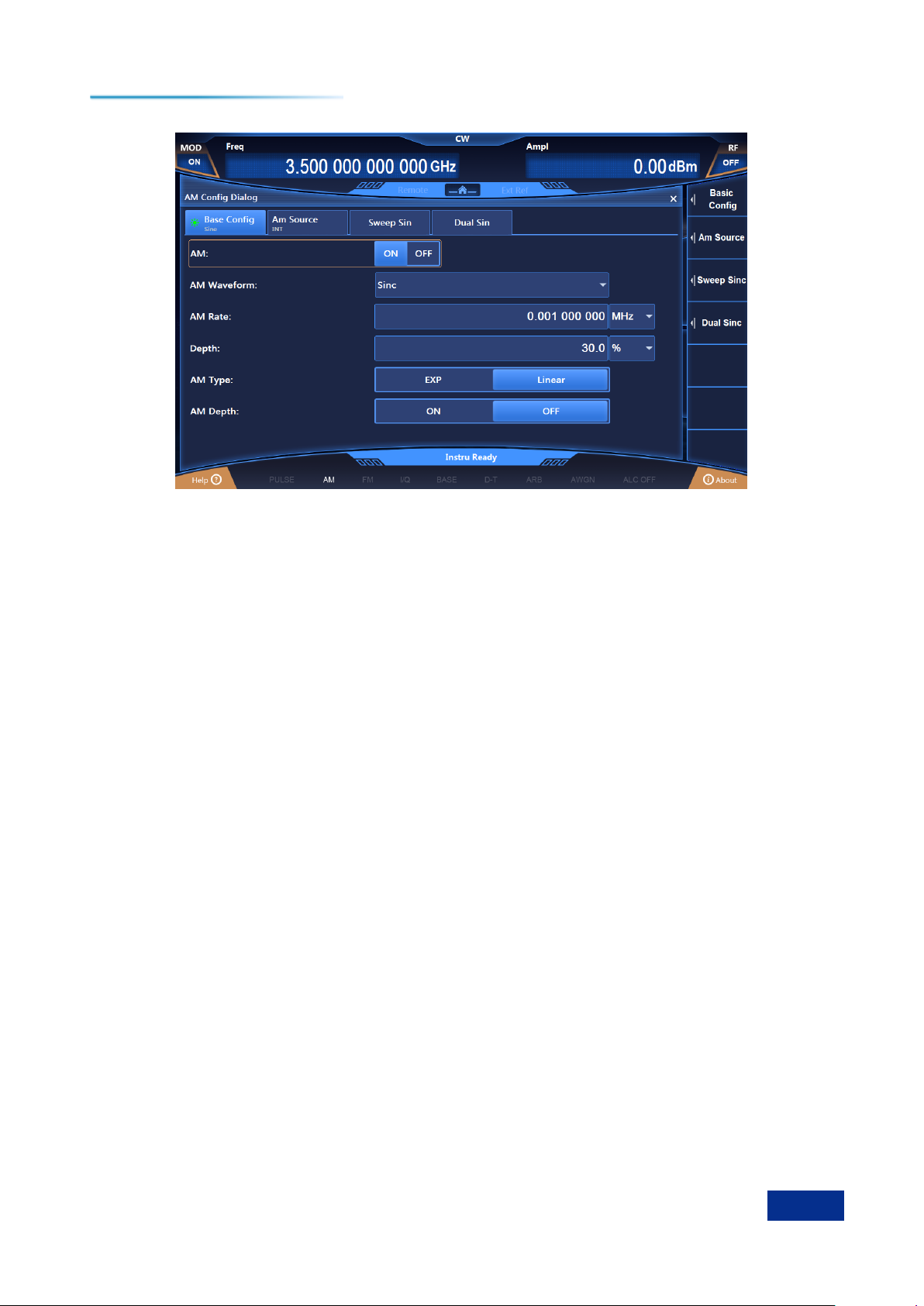
Press the [AM] key or tap [AM] in [Analog Modulation] on the touch screen, and the AM
configuration window will pop up. You may also select the [Modulation On / Off] key to open the
modulation configuration window and switch to the AM configuration window.
Step 3. Set AM waveform:
Rotate the knob clockwise (or counter-clockwise), select the AM waveform combo box, press the
knob, activate the option, press the up / down keys and select the "Sine wave" option; or select the "Sine
wave" option in the AM waveform combo box through the touch screen.
Step 4. Set AM type:
Rotate the knob clockwise (or counter-clockwise) and press the knob to select the "Linear" option of
AM types; or select the "Linear‖ option for AM type on the touch screen.
Step 5. Set AM source:
Rotate the knob clockwise (or counter-clockwise), press the knob, and select the "Internal" option of
AM sources, or select the " Internal" option of AM sources on the touch screen.
Step 6. Set depth AM:
Clockwise (or counterclockwise) turn the knob and select the ―OFF‖ option in Deep AM by pressing
the knob or touching the screen..
Step 7. Set modulation rate:
Rotate the knob clockwise (or counter-clockwise), select the modulation rate input box, and press
the knob to make the modulation rate input box in the editing state; or select the modulation rate input
box on the touch screen to make it in the editing state. Enter 0.001 MHz to end the input.
Step 8. Set AM depth:
Rotate the knob clockwise (or counter-clockwise), select the AM depth input box, and press the
knob to make the AM depth input box in the editing state; or select the AM depth input box on the touch
screen to make it in the editing state. Enter 30% to end the input.
Step 9. RF ON:
Press [RF ON / OFF], or tap the [Power] function area on the touch screen and switch to RF ON to
output RF signals.
At this time, the RF switch state area in the operation interface of the front panel displays "RF ON".
Step 10. Enable AM:
Rotate the knob clockwise (or counter-clockwise), select the AM switch option, and press the knob
to enable AM; or tap the AM switch option on to touch screen to enable AM. At this time, the modulate
indication area of the main information displays , while the text information area displays the
component information of AM in the form of a list, which indicates that AM has been enabled and the
signal generator is outputting AM signals from the RF output connector.
Page 31
3 Typical Applications
25
3.2 Generating AM Signals: LO Frequency of 3.5 GHz, Modulation Rate of 1 kHz, and AM Depth of 30%.
Figure 3.3 Setting AM signals
Page 32
3 Typical Applications
26
3.3 Generating Pulse Modulation Signals: LO Frequency of 3.5 GHz, Pulse Width of 50us, and Period of 1 ms
3.3 Generating Pulse Modulation Signals: LO Frequency of 3.5 GHz, Pulse Width of
50 us, and Period of 1 ms
Step 1. Set RF output signals of the signal generator:
Set CW to 3.5 GHz, power level to 0 dBm, and [RF ON / OFF] to ON.
Step 2. Activate the pulse modulation configuration window:
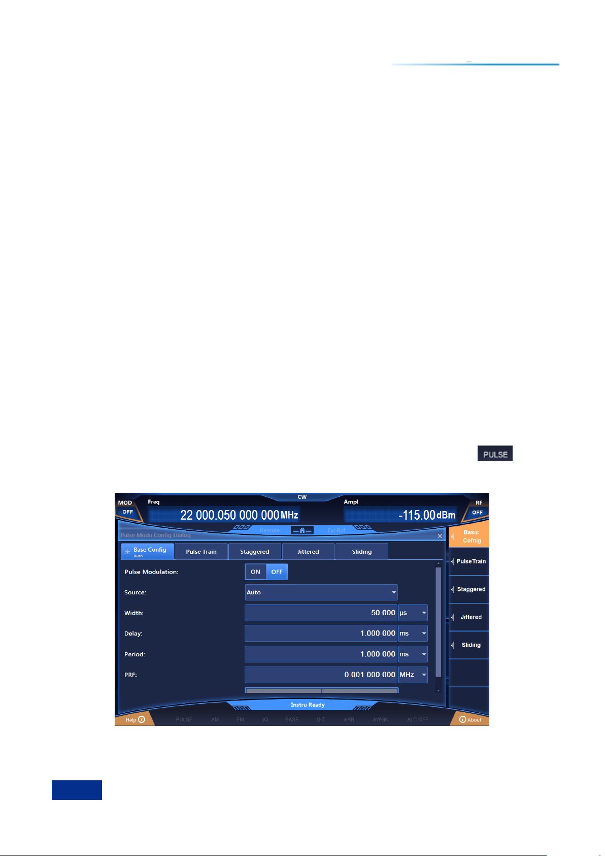
Press the [Pulse] key or tap the [Pulse] function area on the touch screen, and the pulse modulation
configuration window will pop up in the user interface as shown in Figure 3.22.
Step 3. Set pulse source:
Rotate the knob clockwise (or counter-clockwise), select the "Auto" option in the pulse source
combo box, and press the knob to select the ―Auto‖ option; or tap the pulse source combo box on the
touch screen to select the ―Auto‖ option.
Step 4. Set pulse width:
Rotate the knob clockwise (or counter-clockwise), select the pulse width input box, and press the
knob to make the pulse width input box in the editing state; or tap the pulse width input box on the touch
the screen to make it in editing state. Enter 50 MHz to end the input.
Step 5. Set cycle:
Rotate the knob clockwise (or counter-clockwise), select the periodic input box, and press the knob
to keep the periodic input box in editing state; or tap the periodic input box on the touch screen to make it
in editing state. Enter 1 ms to end the input.
Step 6. Enable pulse modulation:
Rotate the knob clockwise (or counter-clockwise), select the ―Pulse modulation switch‖ option, and
press the knob to enable pulse modulation; or tap the pulse modulation switch on the touch screen to
enable pulse modulation. Other options of the pulse configuration window remain at the default values.
At this time, the modulation indication area of the main information display area displays . At the
same time, the text information area displays the component information of pulse modulation in the form
of a list.
Figure 3.4 Setting pulse modulation signals
Page 33
3 Typical Applications
27
3.4 Configuring Step Sweep: Start Frequency of 1 GHz, Stop Frequency of 3 GHz, and 5 Step Points
3.4 Configuring Step Sweep: Start Frequency of 1 GHz, Stop Frequency of 3 GHz,
and 5 Step Points
Sweep function is one of many important functions of signal generators. There are three sweep
modes offered by 1465 series signal generator: Step, list and ramp. The following examples will describe
the configuration and implementation methods of step, list and ramp sweep modes in turn.
Step 1. Activate the Sweep Configuration window:
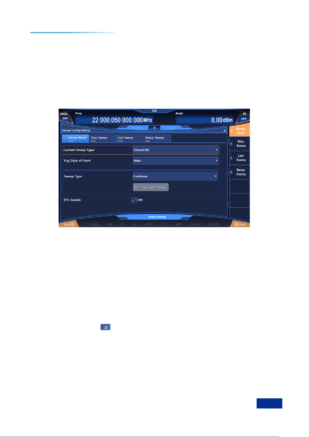
Press the [Sweep] key or tap the [Sweep] function area on the touch screen, and the Sweep
Configuration window will pop up in the operation interface (Figure 3.5).
Figure 3.5 Configuration Window
Step 2. Activate the Step Sweep Configuration window:
Select [Step].
Select the [Sweep mode] option in the sweep configuration window, turn the knob clockwise (or
counter-clockwise), select the [Frequency generation mode] option, press the knob, rotate the knob
clockwise (or counter-clockwise), and select the [Step] option to enable the step sweep mode; or tap the
[Step] option in [Frequency generation mode] on the touch screen to enable the step sweep mode. At
this time, the instrument will automatically sweep by stepping with the current configuration parameters.
Step 3. Configure step sweep parameters:
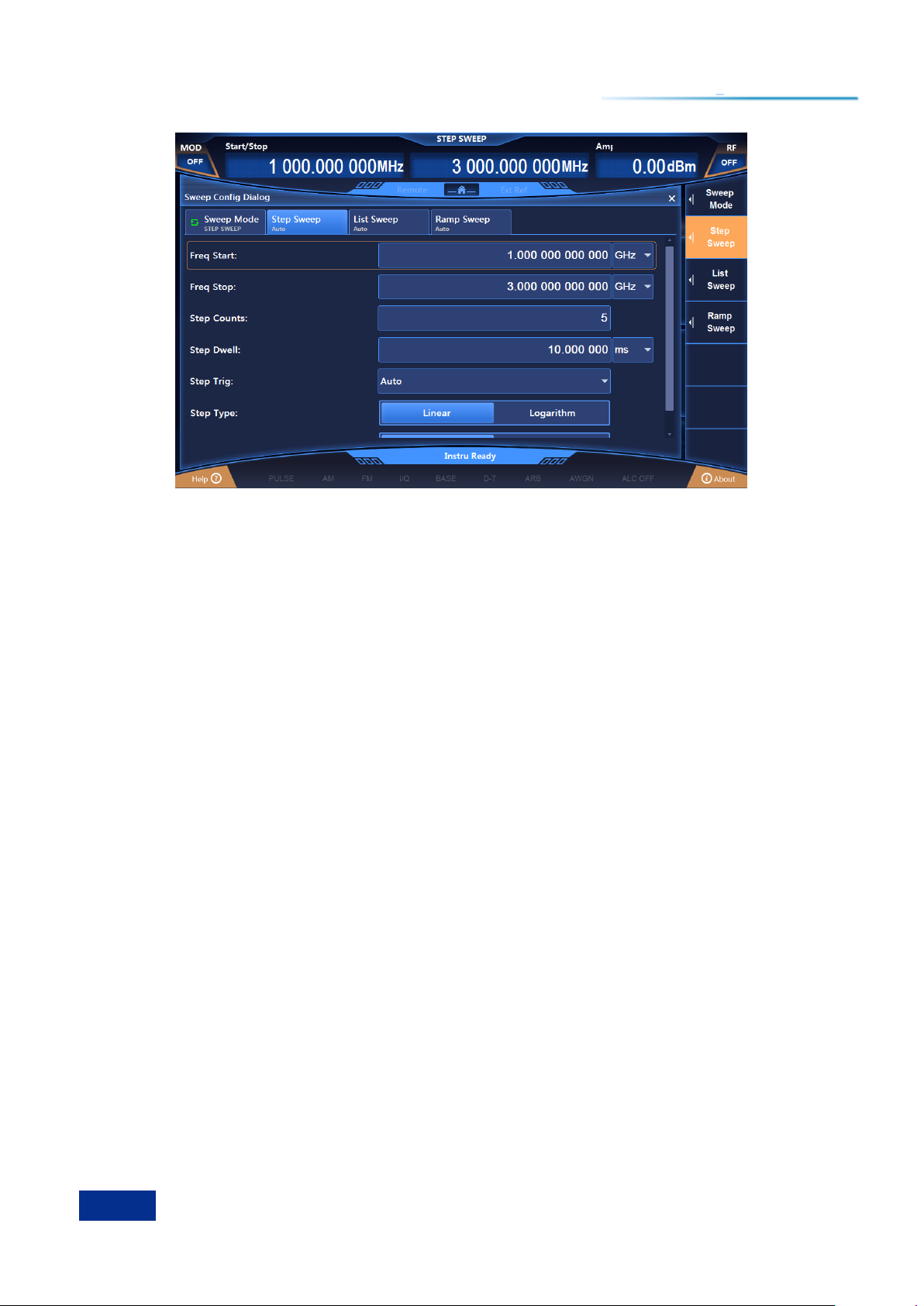
Select the [Step sweep] option of the sweep configuration window, as shown in Figure 3.6. In the
Step Sweep Configuration window, set the start frequency to 1 GHz, stop frequency to 3 GHz, and the
steps to 3.
After the setting, tap the key or keep tapping the [Return] key to close the current window.
Page 34
3 Typical Applications
28
3.4 Configuring Step Sweep: Start Frequency of 1 GHz, Stop Frequency of 3 GHz, and 5 Step Points
Figure 3.6 Configuring step sweep
Step 4: Instrument status display:
After activating the step sweep, the main information display area of the operation interface will
display the start frequency and the stop frequency parameters of stepping.
Page 35

3 Typical Applications
29
3.5 Configuring List Sweep: Start Frequency of 1 GHz, Stop Frequency of 3 GHz, and 5 List Points
3.5 Configuring List Sweep: Start Frequency of 1 GHz, Stop Frequency of 3 GHz, and
5 List Points
Step 1. Activate the Sweep Configuration window:
Press the [Sweep] key or tap the [Sweep] function area on the touch screen, and the Sweep
Configuration window will pop up in the operation interface (Figure 3.5).
Step 2. Activate the List Sweep Configuration window:
Select [List sweep].
Select the [Sweep mode] option in the Sweep Configuration window, rotate the knob clockwise (or
counter-clockwise), select the [Frequency generation mode] option, press the knob, rotate the knob
clockwise (or counter-clockwise), and select the [List sweep] to enable the list sweep mode; or tap the
[List sweep] option in [Frequency generation mode] on the touch screen to enable the list sweep mode.
At this point, the instrument will automatically sweep the list with the current configuration parameters.
Step 3. Configure list sweep parameters:
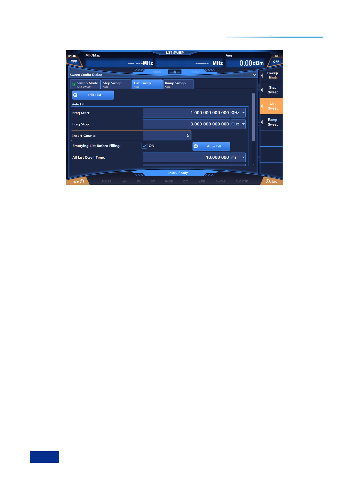
Select the [List sweep] option in the Sweep Configuration window as shown in Figure 3.7. In the List
Sweep Configuration window, there are two methods for configuration.
Method 1: Manual insertion of list points.
Rotate the knob clockwise (or counter-clockwise), select the [Edit list] option, press the knob, select
"Insert frequency point", rotate the knob clockwise (or counter-clockwise) to select the parameters to be
set to make them in the editing state; or select the parameters to be set in the [Edit list] option on the
touch screen to make them in the editing state. List sweep parameters include: CW, offset and dwell time
of the current frequency. Keep inserting frequency points until the sweep list is completed.
Method 2: Automatic filling.
Rotate the knob clockwise (or counter-clockwise), select the start frequency input box, press the
knob to make the start frequency input box in the editing state and input 1 GHz. Similarly, set the stop
frequency to 3 GHz, set the insertion points to 5, rotate the knob clockwise (or counter-clockwise), select
the option [Auto filling], and press the knob to enable auto filling of the sweep list; or select the start
frequency input box on the touch the screen to make the start frequency input box in the editing state
and input 1 GHz. Similarly, set the stop frequency to 3 GHz, set the insertion points to 5, and tap the
[Auto filling] option on the touch screen. The list triggering is set to automatic and the sweep mode is set
to positive. After automatic filling, you can also manually edit the parameters in the edit list. After the
setting, tap the key or keeping tapping the [Return] key to close the current window.
Page 36
3 Typical Applications
30
3.5 Configuring List Sweep: Start Frequency of 1 GHz, Stop Frequency of 3 GHz, and 5 List Points
Figure 3.7 List Sweep Configuration window
Step 4: Instrument status display:
After activating list sweep, the main information display area of the operation interface displays
parameters of list sweep: Minimum frequency and maximum frequency, for instance.
Page 37
3 Typical Applications
31
Tip
3.6 Configuring Ramp Sweep: Start Frequency of 1 GHz, Stop Frequency of 3 GHz
3.6 Configuring Ramp Sweep: Start Frequency of 1 GHz, Stop Frequency of 3 GHz
Step 1. Activate the Sweep Configuration window:
Press the [Sweep] key or tap the [Sweep] function area on the touch screen, and the Sweep
Configuration window will pop up in the operation interface (Figure 3.5).
Step 2. Activate the Ramp Sweep Configuration window:
Select [Ramp sweep].
Select the [Sweep mode] option in the Sweep Configuration window, rotate the knob clockwise (or
counter-clockwise), select the [Frequency generation mode] option, press the knob, rotate the knob
clockwise (or counter-clockwise), and select the [Ramp sweep] option to enable the ramp sweep mode;
or tap the [Ramp sweep] option in frequency generation modes on the touch screen to enable the ramp
sweep mode. At this time, the instrument will automatically conduct ramp sweep with the current
configuration parameters.
Step 3. Configure ramp sweep parameters:
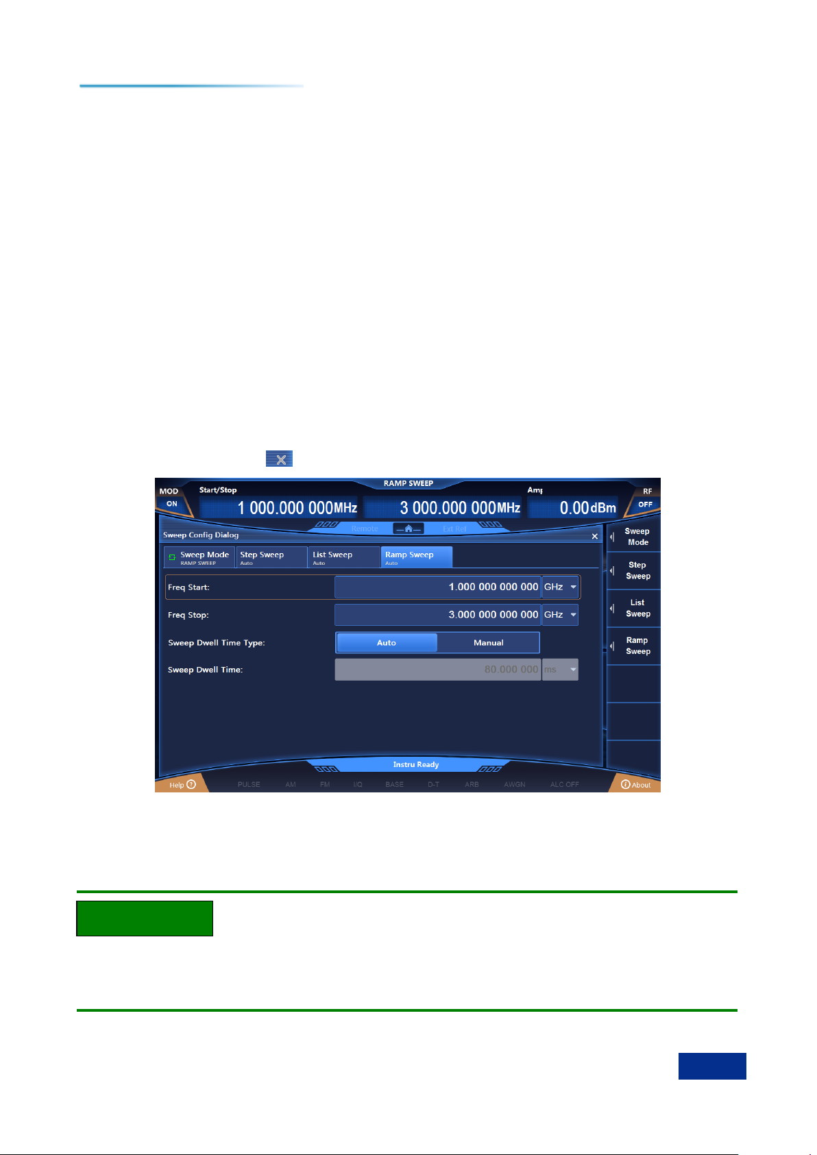
Select the [Ramp sweep] option of the Sweep Configuration window. As shown in Figure 3.8, in the
Ramp Sweep Configuration window, set the start frequency to 1 GHz, the stop frequency to 3 GHz, and
the sweep time to ―Auto‖.
After the setting, tap the key or keeping tapping the [Return] key to close the current window.
Figure 3.8 Ramp Sweep Configuration window
Step 4: Instrument status display:
After the ramp sweep is activated, the main information display area of the operation interface will
display parameters of ramp sweep: Minimum frequency and maximum frequency, for instance.
Sweep State Returns to CW State
To make the instrument returns to the CW state from the sweep state, it is required to set the
[Frequency generation mode] in the Sweep Configuration window to CW.
Page 38
3 Typical Applications
32
3.7 Configuring Baseband: Data Source PN Sequence, Modulation Type QPSK, and Code Element Rate of 4 Msps
3.7 Configuring Baseband: Data Source PN Sequence, Modulation Type QPSK, and
Code Element Rate of 4 Msps
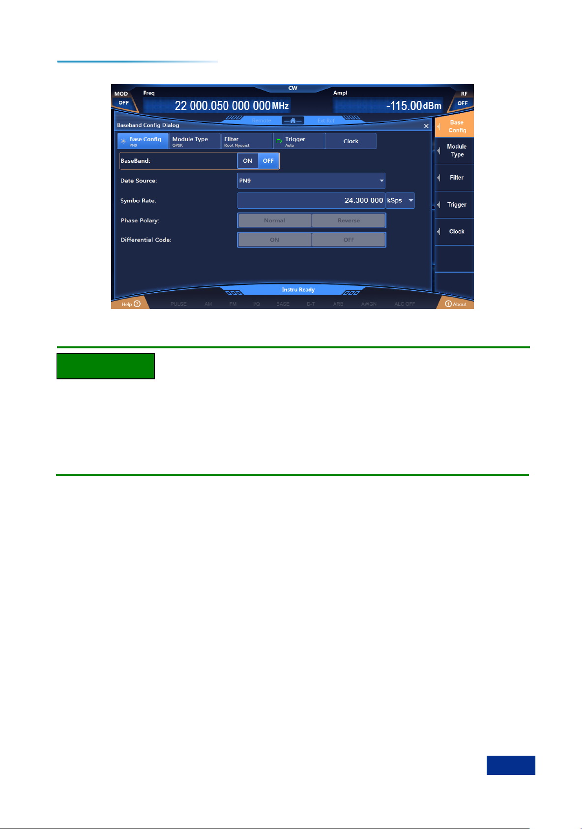
Step 1. Activate the Baseband Configuration window:
Press the [Baseband] key or tap the [Real-time baseband] function area on the touch screen, and
the Baseband Configuration window will pop up in the operation interface (Figure 3.9).
Step 2. Select data source:
Select the [Baseband configuration] option of the Baseband configuration window, rotate the RPG
clockwise (or counter-clockwise), move the focus to the data source selection combo box, press the
knob to display the data source options to be selected; or select the data source selection combo box on
the touch screen to display the data source options to be selected. The data source options to be
selected include: [PN Sequence], [Fixed 4-digit Pattern], [Equivalent 10 Code Pattern] and [File Code
Stream], select the [PN9] option in [PN Sequence].
Step 3. Select modulation type:
Select the [Modulation type] option in the Baseband Configuration window to display the modulation
type currently selected, select the modulation type to "QPSK", or on the touch screen select the [PSK]
option in [Modulation type selection] - > then select the [QPSK / OQPSK] option in [PSK] option - > and
finally select the [QPSK] option in [QPSK / OQPSK].
Step 4. Set code element rate:
Select the [Baseband configuration] in the Baseband Configuration window, rotate the knob
clockwise (or counter-clockwise), select the code element rate input box, and press the knob, or select
[Code element rate] on the touch screen to make the code element rate input box in the editing state; or
select the code element input box on the touch screen to make it in the editing state. Enter 4 Msps to end
the input.
Step 5. Select filter type:
Select the [Filter] option in the Baseband Configuration window, rotate the RPG clockwise (or
counter-clockwise), move the focus to the filter selection combo box, press the knob to select "Root
Nyquist"; or select the [Filter selection] option in the [Filter] option on the touch screen to show the filters
to be selected, and select the [Root Nyquist] option.
Step 6. Enable baseband:
After configuring the baseband parameters, select the [Baseband settings] option in the Baseband
Configuration window, rotate the front panel RPG clockwise (or counter-clockwise), select the real-time
baseband switch, and press the knob to enable the baseband; or select [Real-time baseband switch] on
the touch screen to switch the option to activate the baseband output. At this time, the modulation
indication area of the main information display area will display accordingly.
Page 39
3 Typical Applications
33
Note
3.7 Configuring Baseband: Data Source PN Sequence, Modulation Type QPSK, and Code Element Rate of 4 Msps
Figure 3.9 Configuring baseband
Data Source and Modulation Type Options
If the data source is chosen as "Fixed 4-digit code pattern", it is required to input the code pattern
data, whose scope is 0000 (binary) ~ 1111 (binary), and the display and input in the configuration window
is in displayed and input in decimal with the input range of 0 - 15.
When the modulation type is FSK (2FSK, 4FSK, 8FSK, 16FSK) MSK, in order to get better output,
the filter should be "Gauss".
Page 40
3 Typical Applications
34
3.8 Sequence Playback Function
3.8 Sequence Playback Function
Step 1. Set frequency:
Edit frequency and power, enable RF.
Set the frequency to 10 GHz, the power to 0 dBm, and RF to ON.
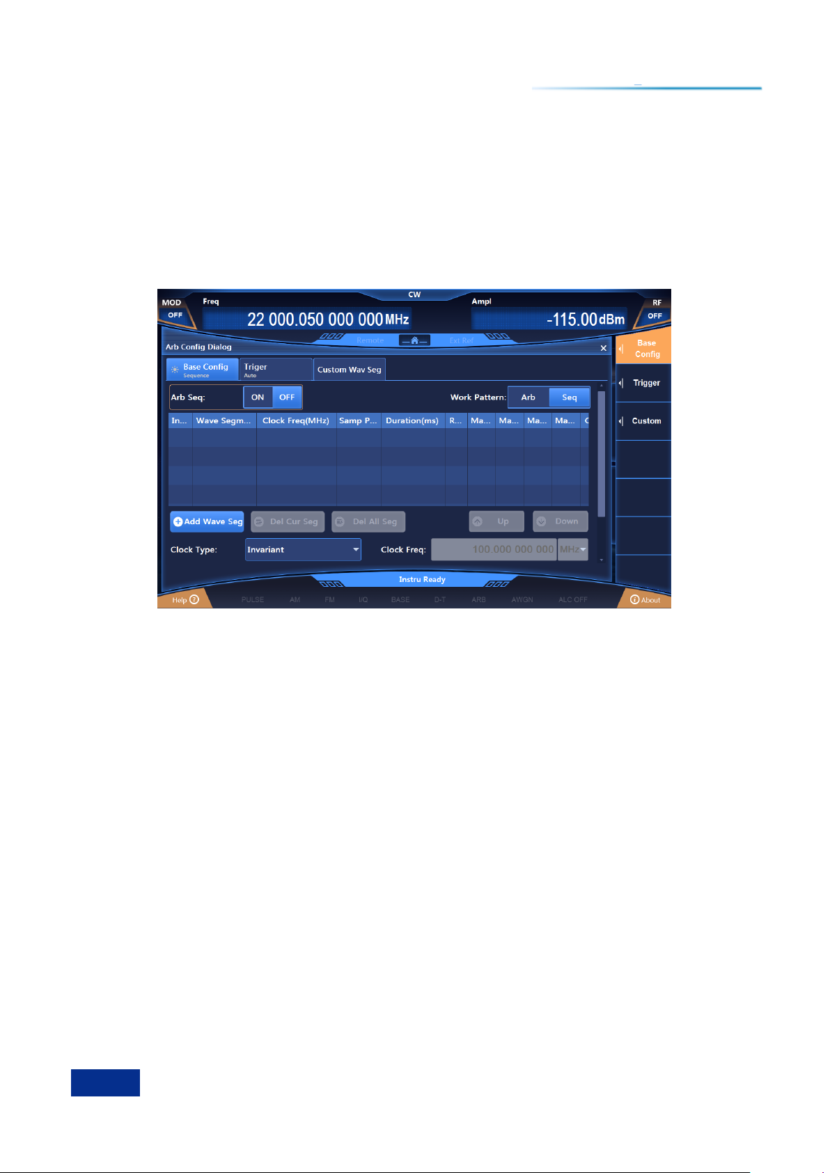
Step 2. Activate the Arbitrary Wave Configuration window:
Tap the [Arbitrary wave] option in the function area of [Signal simulation], and the Arbitrary
Wave configuration window will pop up in the operation interface (Figure 3.10).
Figure 3.10 Arbitrary Wave Sequence Configuration window
Step 3. Setting parameters
Set working mode: Sequence.
Rotate the front panel RPG clockwise (or counter-clockwise), select the "Working mode" option box,
and press the knob to set the working mode to Sequence; or tap the "working mode" option box on the
touch screen to set the working mode to Sequence.
Set clock type: Unchanged.
Rotate the front panel RPG clockwise (or counter-clockwise), select the "Clock type" option box,
and press the knob to set the clock type to Unchanged; or tap the "Clock type" option box on the touch
the screen to set the clock type to unchanged.
This clock type indicates that: The baseband plays at variable sampling rate for each waveform segment,
with the two waveform segments in the sequence played at their default clock frequencies.
Step 4. Add waveform segments
Add waveform segments as required.
Rotate the front panel RPG clockwise (or counter-clockwise) or, in the touch screen mode, select
"Add waveform segment", and select the waveform segment sample file 400KSin_16MClk.seg in the
pop-up window, and add it to the sequence list; then select ―Add waveform segment" again to add the
waveform segment sample file 400KTri_16MClk.seg to the sequence list.
Step 5. Enable arbitrary wave
Select ―Arbitrary wave sequence‖ to ON.
Page 41
3 Typical Applications
35
Tip
3.8 Sequence Playback Function
After configuring arbitrary wave parameters, turn the front panel knob clockwise (or
counter-clockwise), select the arbitrary wave sequence switch, and press the knob to enable arbitrary
wave sequence; or, in the touch screen mode, tap on the arbitrary wave switch to enable arbitrary wave
sequence. At this point, the instrument will automatically download the playback sequence.
Description of Waveform Segment Sample Files
The baseband output of the waveform sample file 400KSin_16MClk is a sinusoidal wave (with
clock frequency of 16 MHz, playback time of 25 ms). Sinusoidal output can be seen by connecting the I
output (or Q output) of the rear panel of the instrument to the oscilloscope.
The baseband output of 400KTri_16MClk is 16M triangular wave (with clock frequency of 16
MHz, and playback time of 25 ms). Triangular wave output can be seen by connecting the I output (or Q
output) of the rear panel of the instrument to the oscilloscope.
Page 42

3 Typical Applications
36
3.9 Arbitrary Wave Playback Function
3.9 Arbitrary Wave Playback Function
Step 1. Set frequency:
Edit frequency and power, enable RF.
Set the frequency to 10 GHz, the power to 0 dBm, and RF to ON.
Step 2. Activate the Arbitrary Wave Configuration window:
Tap the [Arbitrary wave] option in the function area of [Signal simulation], and the Arbitrary
Wave configuration window will pop up in the operation interface (Figure 3.10).
Step 3. Set parameters
Set working mode: Arbitrary waves.
Rotate the front panel RPG clockwise (or counter-clockwise), select the "Arbitrary wave sequence"
option box, and press the knob to enable arbitrary wave sequence; or tap the "Arbitrary wave sequence"
option box on the touch screen to enable arbitrary wave sequence.
Set clock frequency: 100 MHz.
Rotate the front panel RPG clockwise (or counter-clockwise), select the "Clock frequency" input box,
and press the knob to make it in the editing state; or tap the "Clock frequency" option box on the touch
screen to make it in the editing state.
Step 4. Add arbitrary wave files
Load arbitrary waves as required.
Select "Load arbitrary eaves", select the file type Mat-File in the pop-up window, and select the
sample file 1MSin. mat to be added to the list.
Step 5. Set file format
Set the matrix list data type according to ―Configuration by file format...‖
Rotate the front panel RPG clockwise (or counter-clockwise) or through the touch screen, select
"File format configuration..." option box to enable automatic reading of the matrix list in the current mat
file. Select Idata_Int16 from the drop-down list of I matrix, and Qdata_Int16 from the drop-down list of Q
matrix, and Marker Data_int8 from the drop-down list of the Marker matrix. The data type is set by
default. Close the File Format Configuration dialog box and return to the Arbitrary Wave Sequence
Configuration window.
Step 6. Set marker switch
Set markers 1 to 4 to ON in the list.
Step 7. Enable arbitrary wave
Select ―Arbitrary wave sequence‖ to ON.
The instrument can download and play files automatically. Connect the I channel output (or Q
channel output) on the rear panel of the instrument to the oscilloscope, you can see triangular wave
output. Connect markers 1 - 2 on the rear panel of the instrument to the oscilloscope, you can see output
of the edited markers.
Page 43

3 Typical Applications
37
Tip
3.8 Sequence Playback Function
User-defined Arbitrary Wave Data File Format are Supported
The signal generator supports user-defined playback of arbitrary wave data files.
At present, the signal generator supports the conversion of the following five file formats: Mat-File 5,
ASCII, Binary, cap, and csv. The signal generator can convert the five format data files above into
waveform data files .seg (16-bit data) and marker files .mrk, which are used in the signal generator, for
playing.
Page 44

3 Typical Applications
38
3.9 Arbitrary Wave Playback Function
3.10 Selecting ALC Bandwidth
In the internal amplitude stabilization mode, the signal generator adopts automatic level control
(ALC) circuit before RF output.
ALC bandwidth has five options: Auto, 100 Hz, 1 kHz, 10 kHz, and 100 kHz.
In auto mode (reset option), the signal generator automatically selects ALC bandwidth according to
the configuration and settings; when frequency is less than 1 MHz or vector modulation is turned on, the
bandwidth is 100 Hz, the frequency is between 1 MHz and 10 MHz, and the bandwidth is 1 kHz; when
AM is enabled and pulse modulation is disabled, the bandwidth is 100 kHz; in other cases, the
bandwidth is set to 10 kHz. In the non-automatic mode of ALC bandwidth, the bandwidth is set according
to the user's choice.
Operation Steps:
Step 1. Enable ALC bandwidth
Press the [Power] key or tap the [Power] function area on the touch screen, select the [ALC
bandwidth] option in the Power Configuration window, and set "ALC bandwidth manual" to ON.
Step 2. Select bandwidth value
Bandwidth options: 100 Hz, 1 kHz, 10 kHz, and 100 kHz, which can be selected as required.
Limited bandwidths or narrow bandwidths will increase the sampling time of ALC, and can represent the
RMS values of the signals more accurately.
Page 45
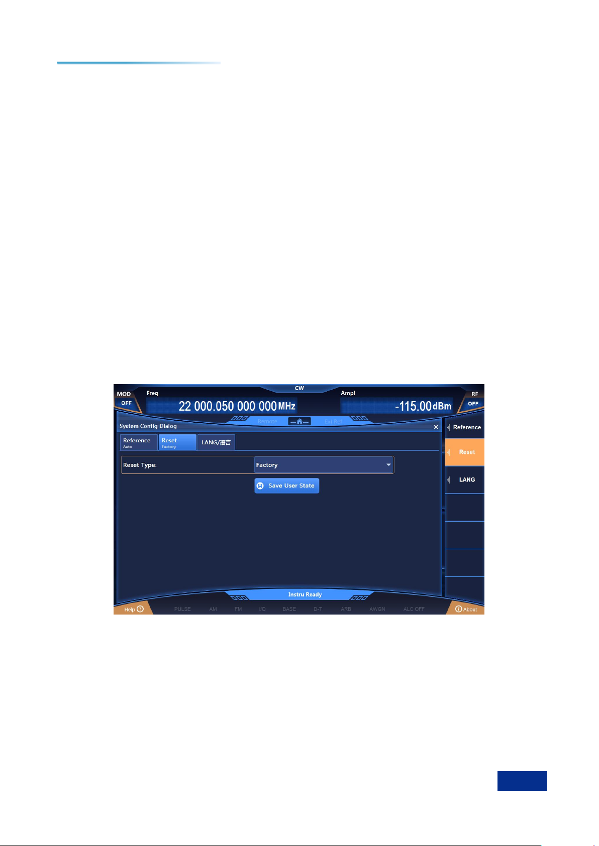
3 Typical Applications
39
3.10 Selecting ALC Bandwidth
3.11 Setting Reset State
The 1465 series signal generator provides users with the option of power-on reset (factory, user and
last state) as the initial state of start-up for measurement. Usually, when the measurement of the
instrument is wrong, users can restore the initial state of the instrument by resetting the instrument state.
The reset state of the signal generator is set as follows:
Step 1. Activate the System Configuration window:
Press the [System] key or tap the [System] function area on the touch screen, and the System
Configuration window will pop up in the user interface. Select the [Reset state] option, as shown in
Figure 3.11.
Step 2. Set reset options:
Rotate the RPG clockwise (or counter-clockwise), select the reset status combo box, press the knob
to activate the option; press the up / down keys or tap the touch screen to switch among "Factory",
"User", And "Last State" to select the setting state when the signal generator is reset.
Select "Factory": Press the [Reset] key, or restart the instrument to make the instrument enter
the default state of factory settings after startup.
Select ―User‖, and tap the ―Save user state‖ key: The instrument will automatically save the
current configuration, presses the [Reset] key, or restart the instrument, the instrument will be initialized
to the settings saved by the user last time.
Select "Last State": Press the [Reset] key, or restart the instrument, and the instrument will
enter the state automatically saved before the last shutdown.
Figure 3.11 Setting the reset state
Page 46
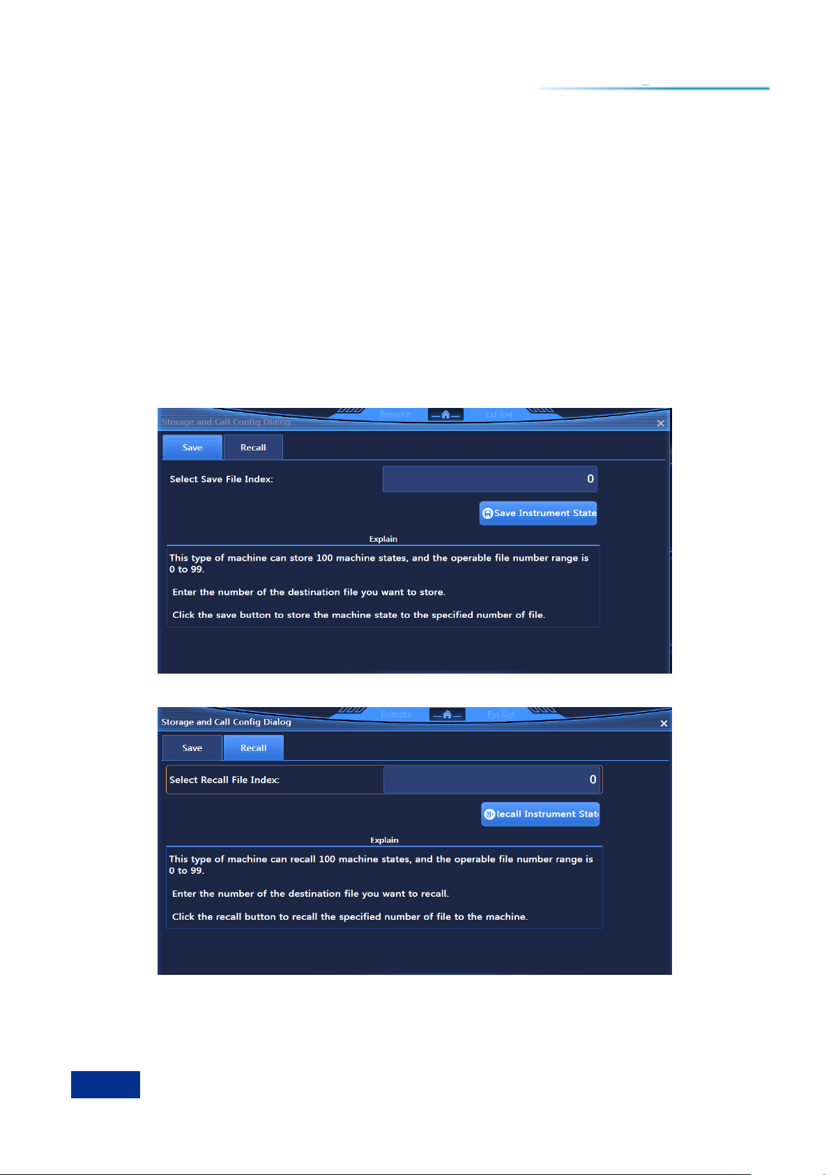
3 Typical Applications
40
3.11 Setting Reset State
3.12 Storing / Calling a User State
The 1465 series signal generator enables users to store and call the measuring state (data) of the
instrument, which can facilitate users to restore the required measuring state for observation and
evaluation again, and save required measuring data for further analysis.
Step 1. Open the Save / Recall Configuration window:
Press the [Save] key, and the Save / Recall Configuration window will pop up in the user interface,
as shown in Figure 3.12.
Step 2. Set Save / Recall file numbers:
Rotate RPG clockwise (or counter-clockwise), or operate on the touch screen to select the "Select
save / call file number" input box, and press the knob to make the input box in the editing state. Enter a
number in the range of 0 - 99 and press the Enter key on the front panel to finish the input. After saving,
wait for a few seconds to complete the saving procedure; after calling, it is also required to wait for more
than ten seconds so that the signal generator can complete the hardware and software settings
according to the selected instrument state.
Figure 3.12 (a) Save Configuration window
Figure 3.12 (b) Recall Configuration window
Page 47

3 Typical Applications
41
Tip
3.12 Storing / Calling a User State
Maximum Number of Instrument States to be Saved / Called
The 1465 series signal generator can save / call up to 100 instrument states, with the state file serial
numbers ranging from 0 to 99.
Page 48
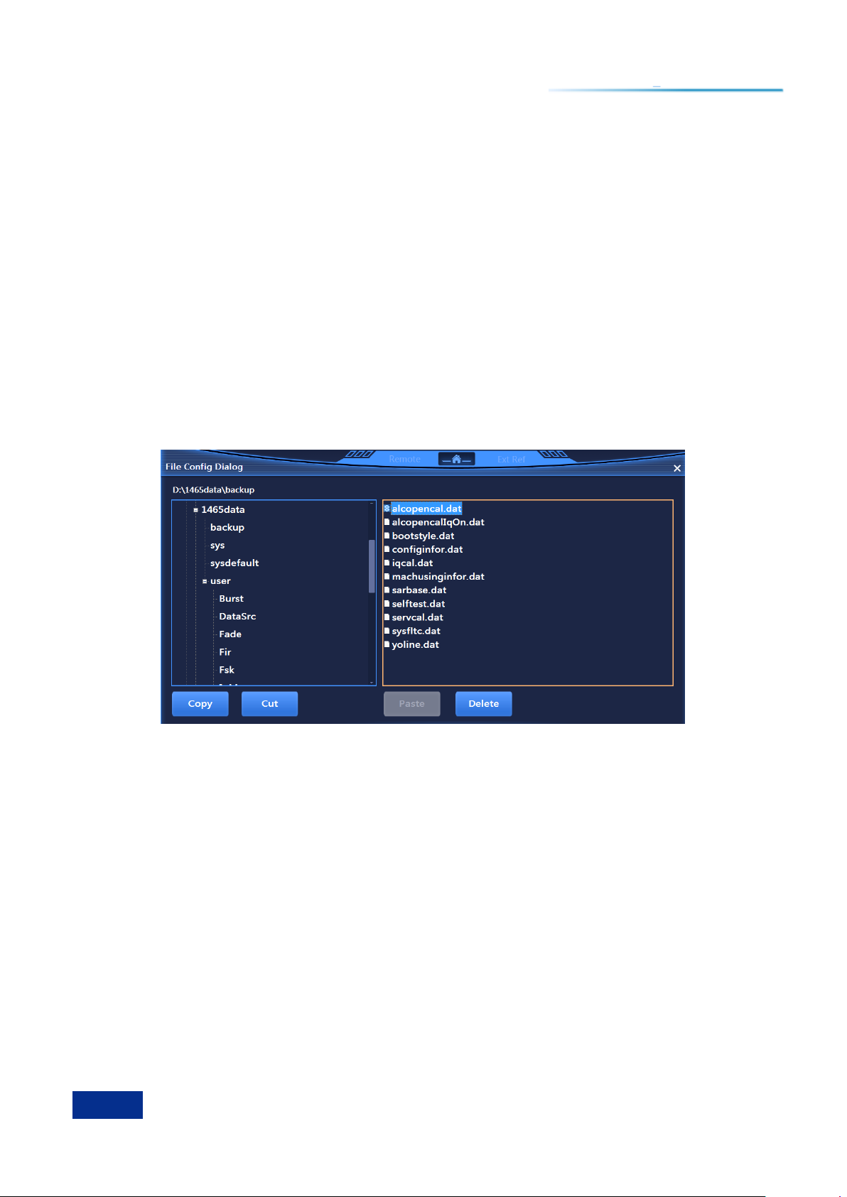
3 Typical Applications
42
3.13 Copying / Moving / Deleting Files
3.13 Copying / Moving / Deleting Files
The 1465 series signal generator provides functions similar to Windows Resource Manager. Users
can browse files conveniently and realize such file operations as copying, cutting, pasting and deletion.
Step 1. Open the File Management window:
Press the [File] key to open the File Management window (Figure 3.13).
Step 2. Select the file directory:
Put the focus on the file directory on the left, then press the up / down keys on the front panel to
switch among file directories of the same level, and press the left / right keys to expand / fold the
sub-directories. When switching directories, the list of files included in the current directory is refreshed
synchronously on the right.
Step 3. Copy / move / delete files:
Select file - > Select ―Copy‖ - > Select ―Paste‖.
Select file - > Select ―Cut‖ - > Select ―Paste‖.
Select file - > Select ―Delete‖.
Figure 3.13 Copying / moving / deleting Files
Page 49

4 Getting Help
43
4.1 Basic Checks
4 Getting Help
Normally, causes of problem come from improper use of hardware and software or incorrect
operation by users. Once a problem occurs, the first step should be observing the error information and
save it, analyze the possible causes and refer to the methods provided in "4.1 Basic Checks" for
troubleshooting. You can also contact our Customer Service Center and provide us with the collected
error information according to the contact information provided in the inside front cover or "4.3 Repair" of
the Guide. We will help you solve the problems as quickly as possible.
Basic Checks …………………………………………………………………………………………43
Help Information ………………………………………………………………………………………44
Repair …………………………………………………………………………………………………45
4.1 Basic Checks
Does the power outlet is active?
Is the signal generator turned on? Check whether the green LED next to the power switch is on.
Pay attention to the noise of the internal fans to judge whether the cooling fans of the signal generator
are running.
If other instruments, cables or connectors are used in conjunction with the signal generator,
ensure that they are connected correctly and working properly.
If the signal generator can't communicate with the LAN, check the Yellow LED beside the LAN
interface on the rear panel. If the indicator does not flash, check the LAN cable and connection.
If the signal generator cannot fully load or run the operating system, or if the application of the
instrument does not start successfully, the problem may be hard drive damage; if the signal generator
startup process cannot be completed after running for enough time, follow the operations described in
"Windows 7 System Recovery" in section "2.2.2.2 System Maintenance".
Does the application run? If not, tap the program startup shortcut icon located on the desktop.
Is the configuration window selected? (Namely, the blue window bar is highlighted) If not, select
the application window with a mouse.
When the problem first occurs, check the measurement steps performed. Are all settings
correct?
If the signal generator does not work properly, press the [Reset] key to return the signal
generator to a known state.
Are the settings performed and their results in accordance with the performance indicators and
characteristics of the signal generator? Please refer to the section on performance indicators and data in
chapter "8 Technical Indicators and Testing Methods" in the User's Manual of the signal generators.
In order to meet the requirements of the signal generator, the signal generator needs to be
calibrated to ensure the correctness of the calibration data by the manufacturer.
Page 50

4 Getting Help
44
4.2 Help Information
4.2 Help Information
When the instrument is not working properly, the operation interface will prompt error information. In
most cases, based on such information, you can query the causes of the errors and find solutions. In the
chapter "7 Fault Diagnosis and Repair" of the User’s Manual, some errors and solutions are described in
detail, and error information is also explained.
In addition, our Customer Service Center can help users at any time to solve any problems
encountered when using 1465 series signal generator. If you provide us with the following information,
we will be able to find solutions for you more quickly and efficiently.
Instrument information: The “Instrument Information” dialog box (press the [Menu] key
or tap the “About” pop-up in the lower right corner of the screen) provides information related to
the following:
– Hardware version information: The cumulative running time of the system, namely the times of
switches, and the firmware version information, namely the version information of optional parts.
– Software Version Information: Version information of software that has been installed in your
instrument, namely, software component version information.
– Instrument error messages: Error files are saved in chronological order.
– About the signal generators: Configuration information of optional parts of the signal generator.
About: In the same window as the instrument information, providing the following
information:
– About the signal generators: Configuration information of optional parts of the signal generator.
– Contact information: Contact information of after-sales services and technical indicators of the
instrument.
Support documents: sys file in the data folder in the main installation directory, which is the
necessary support file for the running of the whole instrument.
Page 51
4 Getting Help
45
Caution
Tip
4.3 Repair
4.3 Repair
When your signal generator has problems that are difficult to solve, you can contact us by telephone
or fax. If it is confirmed after communication that the signal generator needs to be repaired, please pack
the signal generator with the original packaging materials and carton in the following steps:
1) Write a detailed description of the failure of the signal generator, and put it in the carton along
with the signal generator.
2) Pack the signal generator with the original packaging materials to reduce possible damages.
3) Place padding in the four corners of the packing carton, and then place the instrument into the
carton.
4) Seal the opening of the packing carton with adhesive tape and reinforce the packing carton with
nylon tape.
5) Mark "Fragile! Don't touch! Handle with Care!" on the carton.
6) Please consign the instrument as a precision instrument.
7) Keep copies of all transport documents.
Contact information:
Tel.: (86) 0532-86896691
Website: www.ceyear.com
E-mail: [email protected]
Zip Code: 266555
Address: No. 98, Xiangjiang Road, Qingdao City, China
Please Note when Packing the Signal Generator
Using other materials to pack the signal generator may damage the instrument. It is forbidden to use
polystyrene balls as packaging materials. On the one hand, they cannot protect the instrument
adequately, on the other hand, they will be absorbed into the fans of the instrument by electrostatic,
which will cause damage to the instrument.
Packing and Transportation of the Instrument
When transporting or handling this instrument (e.g. due to damage during delivery), please strictly
observe the precautions described in section "2.1.1 Unpacking".
 Loading...