


C-net 2000 MULTI
Users Guide
Issue 08 (V2 series software)


3
Welcome...
All of us at Cetrek would like to welcome you to the
reliable world of Cetrek Autopilot and Control Systems.
Thank you for buying this C-net 2000 MULTI. It is designed
to let you select the information that you want, presented
in the manner most suited to you.
Document
Reference:
806500
Issue 08
Sept 1999

C-net 2000 MULTI
4
EMC Directive 89/336/EEC
This product has been designed to be compliant with the
above Directive.
Maximum performance, and compliance with the EMC
Directive, can only be ensured by correct installation. It is
strongly recommended that the installation conforms with
the following standards:
SMALL CRAFT - ELECTRICAL SYSTEMS:
a) ISO 10133 -Extra Low-Voltage DC Installations
b) ISO 13297 -Alternating Current Installations
ISO = International Standards Organisation
The information contained in this manual is believed to be accurate at
the time of going to print but no responsibility, direct or consequential,
can be accepted by Cetrek Ltd. for damage resulting from the use of this
information. Cetrek Ltd. reserve the right to make changes without
notice to any of its products.
© Cetrek Ltd 1998

5
Contents
1. Using the Instrument ................ 7
2. Speed Information .................. 12
3. Depth Information .................. 14
4. Multi Data Information ........... 16
5. NAV Data Information ............. 18
6. WIND Information ................... 20
7. HEADING Information ............. 22
8. Temperature Information......... 24
9. Battery Voltage Information .... 25
10. Configuration Settings .......... 26
11. Installation............................ 33
12. Alarms .................................. 36
13. Message Formats .................. 37
Index .......................................... 39

C-net 2000 MULTI
6
The C-net 2000 MULTI.
930640 and 930650
LCD (Liquid Crystal Display ) screen.
The C-net 2000 Multi has five soft keys whose function
changes depending on the display, in general the Grey
keys change the displayed information and the Blue key
adjusts viewing conditions.
There is a simple upgrade to convert the Coastal version to
an Ocean version, part number 930022.

7
1. Using the Instrument
1.1 Introduction
There are two versions of the C-net 2000 Multi, Coastal
and Ocean.
Coastal displays: Ocean displays:
‰ Speed ‰ Speed
‰ Depth ‰ Depth
‰ Water Temperature ‰ Water Temp.
‰ Battery Voltage ‰ Battery Voltage
‰ Navigator
‰ Wind
‰ Heading
‰ Rudder Angle
The information can each be displayed in many different
ways, for example:
as a GRAPHICAL display as an ANALOGUE display
as a BIG digital display as a MULTI DATA display

C-net 2000 MULTI
8
1.2 Getting Started
When the self-test routine is complete, the display will
change to show the last viewed information display.
In this example, the Speed Graph display.
When first powered up, the C-net
2000 Multi will
carry out a selftest routine.
Here is shown the
software version.
The ID number.
Checksum
numbers.
The bar chart
gives an
indication of how
far self testing has
progressed.

9
Use the key below this to
increase the lighting
brightness
Use the key below
this to increase the
contrast
Use the key below this to
decrease the contrast
Use the key below this to
decrease the lighting
brightness
Bar graph shows the
setting. This changes
as the keys are
pressed
Use the key below
this to return to
the current
information
display
1.3 Lighting and Contrast
Press the blue button while viewing an information
display, and the LCD lighting and contrast adjustment
becomes available. Adjust these to give the most
comfortable image.
CONTRAST RESET
If the display contrast was to be set so that the
display was unreadable and so could not be
adjusted back, press all four grey keys together.
This will reset the contrast to a central value, reset
the lighting to full and reset the language to
English.
Calibration data will not be lost.

C-net 2000 MULTI
10
ñ
1.4 Changing the Information Display
Press any of the grey buttons, while viewing an
information display, and a pop-up menu will be displayed
at the bottom of the screen.
The menu shows the current function of each button.
After each press of a Grey key the display changes to the
selected Information Display.
If no button is pressed within 5 seconds, the menu will
slowly sink off the bottom of the screen.
Press any Grey button to recall the menu.
SPEED Graph DEPTH Graph MULTI Data 1
SPEED Gauge DEPTH Gauge MULTI Data 2
SPEED Big DEPTH Big MULTI Quad 1
SPEED Statistics DEPTH Statistics MULTI Quad 2
SPEED Log DEPTH Alarms
RACE Timer
Stopwatch
Each press cycles
through the
Speed Displays
Each press cycles
through the
Depth Displays
Each press cycles
through the Multi
Data Displays
Changes the
menu to the
second set of
options
ñ
ñ
ñ
ñ
ñ
These are in the
Ocean and
Coastal
versions
Quad2 is in the
Ocean version
only.

11
Each press cycles
through the
Temperature Displays
Each press cycles
through the
Battery Displays
Changes the
menu to the
first set of
options
NAV Glide Wind Gauge HEAD Digital
NAV Position Wind Tack HEAD Big
NAV D.R. WIND Stats HEAD Tack
NAV Tide Wind Speed HEAD Gauge
NAV Plot WIND Angle HEAD Card
WIND Big HEAD Pilot
WIND Alarm HEAD Rudder
WIND Digital
Each press cycles
through the NAV
Displays
Each press cycles
through the Wind
Displays
Each press cycles
through the Heading
Displays
Changes the
menu to the
third set of
options
ñ
ñ
Temperature Graph Battery Graph
Temperature Gauge Battery Gauge
Temperature Big Battery Big
Temperature Statistics Battery Statistics
ñ
ñ
ñ
ñ
ñ
ñ
ñ
ñ
These are in
the Ocean and
Coastal
versions
These are in
the Ocean
version only

C-net 2000 MULTI
12
2. Speed Information
SPEED GRAPH
Digital display of the vessels speed.
Graph of the speed over the last two minutes.
SPEED GAUGE
A moving pointer representation of the vessels speed, with
a small digital display. The gauge will auto scale to suit the
input data.
SPEED BIG
A digital display using big characters.
SPEED STATISTICS
Displays of the fastest and the average Speed, since the
C-net 2000 Multi was powered up or reset.
Press any Grey key, the menu will now have a RESET
option. This resets both values to the current speed.
SPEED LOG
Displays of Distance and Time, as both Trip and Total.
Press any Grey key, the menu will now have a RESET
option.
This resets both Trip Distance and Trip Time to zero.
Total Distance and Total Time cannot be reset.

13
RACE TIMER
This is a countdown to the start of a race. The timer then
starts counting up to time the race itself.
Press any Grey key, the menu will now have a SET TIMER
option. Press this key, the options are displayed: Set Timer,
Start, Stop and OK. Press the SET TIMER key repeatedly to
select the countdown period required, up to 10 minutes.
Press the START key to start the countdown. An audible
bleep will sound at 5 minutes , 1 minute, then every 10
seconds. A long bleep (3 seconds) is sounded when the
countdown is completed and the Race Timer starts
counting up.
The timer will continue to run, even if you switch to other
displays, until STOP is pressed.
Press the STOP key to stop the Race Timer.
Press the OK key to exit the SET TIMER controls.
STOPWATCH
Press any Grey key, the menu will now have a SET WATCH
option. Press this key and five options are displayed:
START, STOP, LAP TIME, RESET and OK.
Press the START key to start the stopwatch. Press the LAP
key after completing a lap. The lap time is displayed until
the LAP key is pressed again.
Press the STOP key to stop the Stopwatch.
Press the RESET key to reset the Stopwatch to zero.
Press the OK key to exit the SET WATCH controls.
The stopwatch will continue to run, even if you switch to
other displays, until STOP is pressed.

C-net 2000 MULTI
14
3. Depth Information
DEPTH GRAPH
Digital display of the depth of water under the vessel.
Graph of the depth over the last two minutes.
DEPTH GAUGE
A moving pointer representation of the depth, with a
small digital display. The gauge will auto scale to suit the
input data.
DEPTH BIG
A digital display using big characters.
DEPTH STATISTICS
Displays of the deepest Depth recorded, and the average
Depth, since the C-net 2000 Multi was powered up or
reset.
Press any Grey key, the menu will now have a RESET
option. This resets the three values to the current depth.
DEPTH ALARMS
There are four alarms that can be set:
Shallow and Anchor Shallow give alarms when the
measured depth is less than the setting.
Deep and Anchor Deep give alarms when the measured
depth is more than this setting.

15
Shallow/Anchor Shallow increment in one unit,
Deep/Anchor Deep increment in ten units
These alarms
are active
These alarms
are not active
Used to select the alarm
you wish to change
Use to adjust the selected alarm
(Deep Anchor in this example),
a new menu will be displayed
Use to exit the
ADJUST option
Press any Grey key, the menu will now have an ADJUST
option. Press the Blue key.
Used to change
depth of the alarm
Use to return to
the previous menu
Use to switch the alarm
On or Off
Press the OK key in each level of the menu to exit the
ADJUST option.
Depth Alarms are global in a system. The Depth Alarm
settings can be changed at any unit in a system. The
setting will change on every unit in the system.
A pop-up window will be displayed, if an active Depth
Alarm setting is reached. Press any key to clear the pop-up
window.

C-net 2000 MULTI
16
4. Multi Data Information
MULTI Data1
Displays two windows, press a grey key for adjust option.
The black box represents the window changed by that key.
Press the key repeatedly to step through the options that
can be displayed in that window. Stop at the one required.
This selection will be stored for future use.
MULTI Data2
A second display of two windows, adjusted as above.
Choices for display, if the system has the information, are:
Coastal: SPEED, DEPTH, TEMP, DISTANCE.
Ocean: SPEED, DEPTH, TEMP, DISTANCE, HEADING,
POSITION, SOG, COG, WIND_SPEED, WIND_ANGLE.

17
MULTI Quad1
Displays four windows, press a grey key for adjust option.
The black box represents the window changed by that key.
Press the key repeatedly to step through the options that
can be displayed in that window. Stop at the one required.
This selection will be stored for future use.
MULTI Quad2 only on Ocean versions
A second display of four windows, adjusted as above.
Choices for display, if the system has the information, are:
Coastal: SPEED, DEPTH, TEMP, DISTANCE.
Ocean: SPEED, DEPTH, TEMP, DISTANCE, SOG, COG,
HEADING, RUDDER, XTE.

C-net 2000 MULTI
18
5. NAV Data Information
Ocean version only
The Navigator pages repeat information from a Navigation
system. It could be a sophisticated Chart Plotter system or
a simple hand held GPS. The data is received from any
standard NMEA 0183 source. Only one source is allowed.
If the signal is from a Differential GPS, a D will be
displayed in the top right corner of the display
NAV Glide
The first screen shown is the Glide Path view of an
approaching waypoint. The distance, bearing and
waypoint name is shown clearly at the top of the screen.
Also on the screen is the current water speed and depth
reading. The boat symbol at the bottom of the screen
indicates the distance off-track from the direct course to
the waypoint.
NAV Pos
This screen shows the vessels current position, course and
speed.
NAV D.R.
This screen displays dead reckoning information. It uses
boat water speed and compass heading input to calculate
total distance and course made good since power on. Also
available is a RESET function. In the event of a GPS failure
this screen can be used to assist manual navigation.

19
NAV Tide
The display shows the strength and direction of the tidal
flow.
This requires information from the Navigation System
(better with GPS or best with DGPS), an accurately
calibrated water speed sensor and heading input. The
difference between these sensor inputs allows the tidal
stream to be measured.
NAV Plot
A basic plotter screen, showing the recent history of
positions taken once per second. An ADJUST mode
provides a Zoom feature and the ability to store a single
event.
When an event has been stored and is turned on, the
display will indicate the distance and bearing back to the
event. The event data is lost when the power is removed.
The event data is local and is not shared between other
MULTIs in the system.

C-net 2000 MULTI
20
6. WIND Information
Ocean version only
WIND Gauge
A replica of an Analogue display, showing live wind angle
and wind speed. A choice of TRUE or APPARENT and speed
units can be made from the system menu, section 10,
page 26.
WIND TACK
As above, but with an amplified scale for close hauled and
running. The needle is three times more sensitive to
changing wind angle in this mode.
WIND Stats
A useful summary of the highest wind speed, average
wind speed and average wind angle. The statistics have a
RESET option.
WIND Speed
This screen has a 2 hour history of wind speed relative to
the Earth or ground. The current value is shown above the
graph. This allows the trend in the wind strength to be
easily seen.

21
WIND Big
A digital display of Wind Speed using big characters.
WIND Alarm
There are two wind alarm thresholds. Both values can be
adjusted and enabled separately. This is a global function
in a system, the setting can be changed on any Multi and
it changes all in the system. When an alarm is triggered, it
repeats on all MULTIs in the system.
WIND Digital
A display of both wind angle and wind speed in a digital
form. The angle is indicated 0-180 degrees to Port (P) or
to Starboard (S).

C-net 2000 MULTI
22
7. HEADING Information
Ocean version only
HEADING Digital
A large digital display of heading and a tape repeater to
simulate the movement of a compass card.
The ADJUST option provides: locked heading minus and
plus that only work once a heading is locked, heading
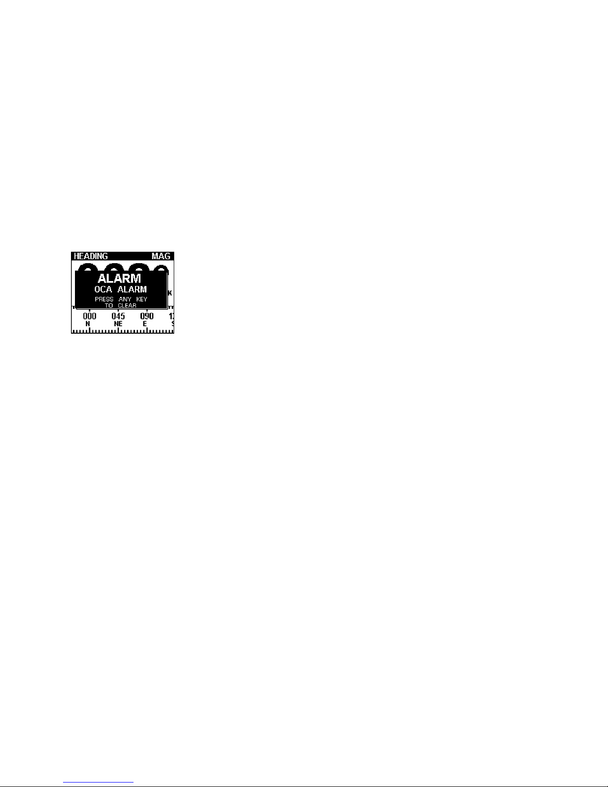
LOCK on or off,and OCA (off course alarm) function.
If a heading is Locked and the vessel is slightly off course,
the bar graph above the tape repeater shows the direction
and the amount of deviation from the locked course.
The Off Course Alarm function will only work if the
heading is locked and the alarm switched on.
The bell symbol indicates the alarm is on.
The alarm can be set in 5º steps.
HEADING Big
A digital display of heading in big characters.

23
HEADING Tack
The ADJUST function for this display screen allows two
tack angles to be stored. The bar graph at the top of the
screen indicates a change of course from the entered
values in the form of a HEAD or LIFT function. The current
locked value is taken as the closest stored value and this
can be fine tuned with the LESS /- and MORE/+ keys.
HEADING Gauge
A steering compass with a moving pointer and digital
read-out.
HEADING Card
A steering compass with rotating card and digital read-
out.
HEADING Pilot
A repeater function for a Cetrek Autopilot. Operates only
with a Pilot Computer with V2 or later software.
HEADING Rudder
A large clear rudder angle indicator for a Cetrek Autopilot.
Operates with a Pilot Computer with V2 or later software.

C-net 2000 MULTI
24
8. Temperature Information
TEMPERATURE GRAPH
Digital display of the Water Temperature around the vessel.
Graph of the Water Temperature over the last two hours.
TEMPERATURE GAUGE
A bulb thermometer representation of the Water
Temperature, with a small digital display.
TEMPERATURE BIG
A digital display using big characters.
TEMPERATURE STATISTICS
Displays of the highest and lowest recorded, and the
average Water Temperature, since the C-net 2000 Multi
was powered up or reset.
Press any Grey key, the menu will now have a RESET
option. To reset to the current temperature, press the Blue
key.

25
9. Battery Voltage Information
BATTERY GRAPH
Digital display of the supply voltage.
Graph of the supply voltage over the last two hours.
BATTERY GAUGE
A moving pointer representation of the voltage, with a
small digital display.
BATTERY BIG
A digital display using big characters.
BATTERY STATISTICS
Displays of the highest and lowest recorded, and the
average Battery Voltage, since the C-net 2000 Multi was
powered up or reset.
Press any Grey key, the menu will now have a RESET
option. To reset to the current battery voltage, press the
Blue key.

C-net 2000 MULTI
26
10. Configuration Settings
Press and hold the blue (righthand) button, and you select a
group of configuration settings that, once set, rarely need
changing.
Each system menu option has a similar layout to the example
above.
The bar graph indicates
that there are more
options in the list but
not currently displayed,
CONFIG for instance.
Used to select the option
you wish to change
Use to adjust the selected
option (Units in this example),
a new menu will be displayed
Use to exit the
ADJUST option
UNITS
This option allows the setting of the following:
Speed ............... Knots, MPH or KPH
Depth ............... Meters, Feet or Fathoms
Temperature ...... Celsius or Fahrenheit
Distance Units ... Nm, Miles or Km
extra on Ocean versions:
Wind Angle ....... Apparent, True
Wind Speed....... Knots, m/s, MPH, Beaufort
Bearing ............. Mag, True
Select the units to be displayed, on any C-net 2000 Multi
in a system. This information is Global and will be used
by all other MULTIs in the system.

27
CALIBRATION
The Speed option changes the speed transducer reading
by the percentage set here.
It is also possible to calibrate automatically against a GPS
speed input. If there is very little tide and the GPS is giving
good Speed Over Ground information, press AUTO key and
the MULTI will calculate the correct percentage value to
ensure that both water speed and ground speed are
identical.
The Depth Offset option allows a fixed dimension to be
added or subtracted from the depth reading. This allows
compensation for keels, or depths from the water surface
to be displayed.
only on Ocean versions:
The windvane may require fine adjustment to ensure that
it reads zero angle with the wind direction dead ahead.
Use this screen to rotate the wind angle so that it reads
correctly. This adjustment also corrects any WIND or TACK
units connected in the system.
only on Ocean versions:
This is used for directly connected compass systems that
respond to a remote trigger for calibration, such as those
using 930541/930543 interfaces. This page starts the
calibration run directly from the MULTI. If the compass
calibration reads CLEAR, go directly to Step 2. If the
compass status reads CORR, the current compass
calibration needs to be removed as in step 1.
When connecting to a heading source from a Cetrek
Autopilot System, Calibration and Alignment is done as
part of the Autopilot installation. Do not calibrate or Align
it from here.
STEP 1 1.1 Switch the system OFF
1.2 Remove the top cover from the 541/543 compass
interface, and locate the calibration link (LK1).
1.3 Remove the black jumper from the calibration link
pins and apply it to the two pins of LK2, that are next to
LEDs 1 & 2.

C-net 2000 MULTI
28
1.4 Switch the power back on and wait for the C-net 2000
to completely power up, and then switch the power off.
1.5 Remove the jumper from LK2, and replace it in the
original position on the calibration link.
1.6 Replace the cover, and switch the system power back on.
STEP 2 2.1 Return the C-net 2000 to the compass calibration
page and resume the calibration routine:
2.2 Press Cal Now button. (Compass status will change
to INT).
2.3 As soon as the vessel starts to move, in a clockwise
direction, the status will change to RUN.
2.4 When the compass has completed its deviation turns,
the compass status will read CORR.
Compass calibration is now complete.
This next setting allows the compass reading to be aligned
to a known, correct heading. Use the keys to adjust the
heading reading to the correct one.
DAMPING
This allows readings to be damped if they change too fast
so that they change slower and can be read.
The range is 0 (undamped) to 9 (maximum damping).
LANGUAGES
The language used on all C-net 2000 units in the system is
changed here.

29
BLEEP
The internal bleeper sounds each time a key is pressed.
This can be disturbing on a night watch when some of the
crew are resting. Turning this option to off will silence the
key bleep. The audible alarm functions are unaffected. This
function only affects the local unit and remains set until
changed.
LIGHTING
The lighting on each MULTI can be set as LOCAL, GROUP A
or GROUP B,
If set to LOCAL, changing its lighting level will affect only
that unit.
If set to GROUP A or B, when the light level is changed on
any MULTI in the same group, all MULTIs in that group will
change.
Two groups are available so that for example, one group
could be inside, the other outside.
Selecting the Lighting option in the Lighting menu sets
the level that the lighting be when the system is powered
up. The choices are: LAST (previous value), 0 (OFF), 1 ,2
and 3.
If you wish the start-up lighting to be always on high, then
set this value to 3.
The setting changes all MULTIs in the group.

C-net 2000 MULTI
30
CONFIG MENU
The settings in this menu should only be used with caution
by trained personel.
The NMEA Filter is an extremely powerful method of
controlling the NMEA 0183 input and output data flow.
Individual messages can be masked to ON or OFF for each
of the three input channels and the single output channel.
The messages are listed individually or all messages can be
masked on or off with the all option.
Here all the NMEA messages are turned on for all
channels.
Here the MWV message for input three has been removed.
This message is then ignored on that input channel.
This can be used to break message loops that some
system configurations cause.
The Demo option selects a demonstration display that will
run without having any transducers connected.

31
The Reset All option resets all settings back to a default
value and should be used with caution as all calibration
data will be lost.
The programme from one MULTI can be copied across the
CAN bus to other MULTIs and also to WIND or TACKs. The
Upload feature will be described with the upgrade kits.
The Self Test provides diagnostic information and has a
very useful NMEA viewer.
The other options are for factory use only.
Press the key to select the required NMEA channel.
Press the same key again to freeze the display for
examination of the data.

C-net 2000 MULTI
32
Bulkhead Mounting
Trunnion Mounting
Trunnion Mounting Kit
is available,
Part Number 930293
Specifications
Supply 12V nominal
(10.5V to 15.0V)
max. CAN link 30 units
NMEA inputs 3 per unit
NMEA outputs 1 per unit
Dimensions 110mm x 110mm
(4.3 x 4.3)
max. Stud depth 7mm
Weight 290g (9.3oz)
Operating temp. 0º to +55ºC
Storage temp. -20º to +70ºC
Environmental Weatherproof from front,
back must be protected.

33
11. Installation
11.1 Mounting the instrument
Decide on a location.
Allow adequate clearance behind the unit for cable
connections to ensure that the cables are not unduly
stressed.
Ensure that there is sufficient length of cable to remove
the unit for servicing purposes.
Ideally, if the rear of the C-net 2000 is going into an
enclosed area, that the area should be adequately
ventilated so that the rear sees the same ambient
temperature as the front.
Most units will be mounted in a bulkhead and that
method is described here. A Trunnion mounting kit is also
available, Part Number 930293.
Using the supplied template as a guide, cut out the
hole for the back and drill the four ø 4.3 mm (0.170)
holes for the studs.
Screw the four
studs into the rear
case, longer M4
studs can be used
if required (not
supplied).
Connect the cables
to the rear of the
unit.
Place the unit into
position, then
secure it by
screwing the
thumb nuts onto the studs.
Not to Scale

C-net 2000 MULTI
34
11.2 Connections
GENERAL
Try to keep cable runs as short as possible to reduce the
risk of voltage drop and interference.
All cable runs should be kept at least 100mm (4) from
other cables carrying RF (Radio Frequency) or pulsed
signals.
If it is necessary to extend any of the data cables, the same
type of cable must be used and the screens must be
carried through.
SUPPLY
The supply must be 12 volt, from the switched side of a
Circuit Breaker and be fused, or protected, at 500 mA per
unit. For CAN Link runs totalling more than 10m, it is
advisable to supply power at both ends of the link, from
the same breaker.
TRANSDUCER & DATA INPUTS
NMEA 0183 instrument data can be connected to any
spare input of any unit in the system, (with the exception
of the Cetrek 3400 which cannot use NMEA 1 inputs).
Ensure only one source per input. The data is shared
throughout the system.
The Masthead Sensor 930387, the Speed/Depth interface
930346, Compass interfaces 930541 or 930543, GPS,
Navigator or Plotters all use this method.
Wire them to the 10 way terminal block on the back.
12V supply
+ve, -ve
NMEA 1 input
(RX) +ve, -ve
+ve, -ve
NMEA 2 input (RX)
NMEA 3 input
(RX) +ve, -ve
-ve, +ve
NMEA output (TX)
pin 1
PL1 Pin-out
Details
BUS TERMINATION
The Bus Termination resistor must be fitted to the Power
lead connector of the unit at each end of the CAN link.
SCREEN CONNECTION
Where a Screen/Chassis/Ground connection is available,
(NOT SS-ve), connect all Screens to this point.

35
Connecting a Single MULTI to the 931659
Transducer Pack
Connect the transducers to the interface box as explained
in the leaflet that comes with the transducer pack.
Connect the NMEA and power leads as shown here.
Connecting a System
The two 5way connectors at the rear of this product are
for the high speed CAN bus data link. This operates at
250Kbit/sec. which is 52 times faster than NMEA 0183.
MULTI, WIND and TACK units can all be in one system, in
any sequence.
Link cables are available, Part Numbers:
930030 = 5m Link cable, 930031 = 10m Link cable
When fitting a new unit to an existing system, ensure all
calibration settings are checked and reprogrammed, as
per the calibration procedure on page 27.
930346
C-net 2000 MULTI
36
12. Alarms
NO DATA
Dashes will be displayed, on the information displays, if
data has not been received.
Check the connections to the sensor/transducer.
Check the sensor/transducer itself.
DATA LOST
A alarm window will pop up giving details of the alarm
condition.
Check the connections to the sensor/equipment.
Check the sensor/equipment itself.
DEPTH ALARM, WIND ALARM and HEADING ALARM
When an active Alarm is reached a pop-up window will be
displayed, press any key to clear the alarm.
RACE TIMER AUDIBLE ALARM
An audible alarm sounds at 5 minutes , 1 minute, then every
10 seconds. A three second long bleep is sounded when the
countdown is completed and the Race Timer starts.

37
13. Message Formats
All C-net 2000 Instruments read, combine and output the
following NMEA 0183 (version 2) messages :-
APA APB BOD BWC BWR DBT DPT GGA GLL
HDG HDM HDT MTW M W V RMA RMB RMC RSA
VHW VLW VTG VWR WAS WDC XTE
Also used are two proprietary messages:-
$PCETP $MNXT

C-net 2000 MULTI
38
Index
A
Alarm
Race Timer Audible Bleep
............................... 13, 36
Alarms ............................. 36
amplified scale .................. 20
Anchor alarms ................... 14
audible alarm .................... 28
average Speed ................... 12
B
Battery Information .. 7, 11, 25
Battery Voltage Information 25
boat symbol ...................... 18
brightness .......................... 9
Bus Termination ................ 34
C
C-net Bus ......................... 33
Cable Routing ................... 34
Calibration
Depth Offset .................. 27
Speed ........................... 27
calibration ........................ 27
Changing Information ........ 10
Circuit Breaker .................. 34
Configuration Settings ...........
............................ 26, 36, 37
Connecting a Single Display 35
Connecting a System ......... 35
Connections ...................... 34
contrast .............................. 9
contrast reset ...................... 9
D
damping .......................... 28
Dashes ............................. 36
Data display ...................... 16
dead reckoning ................. 18
Demo ............................... 30
Demo Option .................... 30
Depth Alarms ............... 10, 36
Depth alarms .................... 14
Depth Information ......... 7, 14
Depth Offset ..................... 27
display image ...................... 9
Distance ........................... 12
E
event ............................... 19
F
four windows ................... 17
Fuse ................................. 34
G
Glide Path ......................... 18
H
Heading Information ......... 22
I
ID number .......................... 8
image ................................ 9
Information Display ............. 7
Installation ....................... 33
Interference ...................... 34
K
keys ................................... 7
L
language .......................... 28
lighting .............................. 9
lighting group ................... 29
lighting start up ................ 29
Link cables ........................ 35
location ............................ 33
M
Menu Display
Pop-up .......................... 10
Sinking ......................... 10
menus .............................. 10
Mounting ......................... 32
Multi Data Information ..........
....................... 10, 16, 18, 20
N
Navigator pages ................ 18
NMEA 0183 messages ........ 37
NMEA Filter ...................... 30
NMEA Input ...................... 35
NMEA Messages ........... 36, 37
NMEA viewer .................... 31
O
Ocean ................................ 7
off course alarm ................ 22
off-track ........................... 18
P
plotter screen .................... 19
Pop-up Alarm Window ....... 36
Pop-up Depth Alarm Window
.................................. 15, 36
Pop-up Menu .... 10, 13, 14, 26
Q
Quad display ..................... 17
R
Race Timer ................... 13, 36
Radio Frequency ................ 34
Reset All ........................... 31
RF (Radio Frequency) .......... 34
rudder angle indicator ....... 23
S
Screening ......................... 34
Self Test ............................ 31
self-test routine ................... 8
software version .................. 8
specifications .................... 32
Speed Information .... 7, 10, 12
Speed Log ............. 10, 11, 12
Stopwatch ................... 10, 13
supply .............................. 34
T
Tack ................................. 23
Temperature Information ........
.............................. 7, 11, 24
Template .......................... 33
thermometer .................... 24
Tide ................................. 19
Time ................................ 12
Transducer Pack ................. 35
Trip .................................. 12
Trunnion ........................... 33
two windows .................... 16
U
units ................................ 26
unreadable ......................... 9
Upload ............................. 31
V
voltage drop ..................... 34
W
Wind Information .............. 20
windvane zeroing .............. 27


 Loading...