


NEMESYS
Hardware Manual and Reference
OR IGINAL INSTRUCTIONS 2.0 8– AUGUST 2018

2 neMESYS Hardware Manual
CETONI GmbH
Wiesenring 6
07554 Korbussen
Germany
T +49 (0) 36602 338-0
F +49 (0) 36602 338-11
E info@cetoni.de
www.cetoni.de

neMESYS Hardware Manual 3
The information and data contained in this document are subject to change without notice. CETONI
GmbH is constantly striving to develop all its products. This means that there may be changes in form,
equipment and technology. Claims cannot therefore be made on the basis of information, illustration or
descriptions in these instructions. The description for the product specification in this manual does not
constitute an integral part of the contract.
If you control the products with a software from CETONI GmbH, you agree to the applicable license
agreement, which can be read in the corresponding software manual. This and all other current product
manuals can be found at https://www.cetoni.de/en/downloads/manuals.
The reproduction, distribution and utilization of this document as well as the communication of its
contents to others without explicit authorization are prohibited. Offenders will be held liable for the
payment of damages.
We are always open to comments, corrections and requests. Please send them to info@cetoni.de.
The general terms and conditions of CETONI GmbH shall apply. Alternative agreements must be in
written form.
Copyright © CETONI GmbH – Automation and Microsystems. All rights reserved.

4 neMESYS Hardware Manual
1 Overviews and Directories
1.1 Table of Contents
1 Overviews and Directories 4
1.1 Table of Contents 4
1.2 Revision History 7
2 Introduction 8
2.1 Foreword 8
2.2 Symbols and Key Words Used 8
2.3 Norms and Guide Lines 9
2.4 Application Purpose 9
2.4.1 General Description of the Advice 9
2.4.2 Intended Use 9
2.4.3 Reasonably Foreseeable Faulty Application 9
2.4.4 Safety Advice 10
2.4.5 Measures for Safe Operation 11
2.4.6 Safety Devices on the System 11
2.4.7 Condition of the Devices 11
2.5 Warranty and Liability 12
2.6 Scope of Supply 13
3 Initial Start-Up 14
3.1 Software Installation 14
3.2 System Configuration 14
3.2.1 Connecting the Base Module 15
3.2.2 Connecting Additional Modules 16
3.3 Module Configuration 18
4 Base Module BASE 120 19

neMESYS Hardware Manual 5
4.1 Technical Data 19
4.1.1 Environment 19
4.1.2 Mechanical Data 19
4.1.3 Electrical Data 20
4.1.4 Interfaces 20
4.2 Transport and Storage 20
4.3 Maintenance and Care 20
4.4 Hardware Operation 21
5 Low Pressure Syringe Pump 22
5.1 Technical Data 22
5.1.1 Environment 22
5.1.2 Mechanical Data 22
5.1.3 Electrical Data 23
5.1.4 Interfaces 23
5.1.5 Dosing Performance 23
5.1.6 Valve 24
5.2 Transport and Storage 24
5.3 Maintenance and Care 25
5.4 Hardware Operation 25
5.4.1 Mounting a Syringe 26
5.4.2 Fluidic/Valve 29
6 Mid Pressure Syringe Pump 32
6.1 Technical Data 32
6.1.1 Environment 32
6.1.2 Mechanical Data 32
6.1.3 Electrical Data 33
6.1.4 Interfaces 33
6.1.5 Dosing Performance 34
6.2 Transport and Storage 35
6.3 Maintenance and Care 35

6 neMESYS Hardware Manual
6.4 Hardware Operation 35
6.4.1 Mounting a Syringe 36
6.4.2 Fluidic/Valve 39
6.4.3 Mounting the Blank Holder 41
7 High Pressure Syringe Pump 42
7.1 Technical Data 42
7.1.1 Environment 42
7.1.2 Wetted Parts 42
7.1.3 Mechanical Data 43
7.1.4 Electrical Data 43
7.1.5 Interfaces 43
7.1.6 Dosing Performance 44
7.2 Transport and Storage 45
7.3 Maintenance and Care 45
7.4 Hardware Operation 45
7.4.1 Mounting the Safety Hood 46
7.4.2 Fluidic Connections 47
7.4.3 Mounting a Syringe 49
7.4.4 Pressure Sensor 51
8 Accessory Port 53
9 RS232 Connection 55
9.1 Pin Assignment of Module Interfaces 55
9.2 OEM RS232 Cable Set 55
9.2.1 RS232 Wiring 55
9.2.2 Communication Settings 56
9.2.3 Pin Assignment of the RS232 Cable 56
10 Disposal 57

neMESYS Hardware Manual 7
1.2 Revision History
RE V
DATE
CH AN GE
2.00
21.06.2013
Manuals merged
2.01
06.02.2014
Adaption of the pin assignment table
2.02
29.01.2015
Correction of pin assignment table
2.03
07.09.2015
Removed cable colors for I/O interface
Added safety advices about the Pressure Equipment Directive
2.04
19.10.2015
Correction of the pin assignment of the I/O-Interface for the High Pressure Syringe Pump
2.05
10.03.2016
New Corporate Design
2.06
21.11.2016
Correction of pin assignment table
2.07
29.05.2017
Pictures BASE module and USB cable updated
2.08
06.08.2018
Pressure sensor type in High Pressure Syringe Pump changed

8 neMESYS Hardware Manual
2 Introduction
2.1 Foreword
Thank you for deciding to purchase a CETONI product. We would like to support you with this
handbook as far as possible in your interaction with the neMESYS syringe pump system. We are directly
available for any questions or suggestions that you may have.
The neMESYS syringe pump system may only be taken in operation after carefully reading and
understanding this manual. We wish you much success in your work with the neMESYS syringe pump
system.
2.2 Symbols and Key Words Used
The following symbols are used in this manual and are designed to aid your navigation through this
document:
HINT. Describes practical tips and useful information to facilitate the handling of the
software.
IMPO RT AN T. Signifies important hints and other useful information that may not
result in potentially dangerous or harmful situations.
ATTE NT IO N. Identifies a potentially harmful situation. Failure to avert this situation
may result in damage to the product or anything in its proximity.
CAUTION. Indicates a potentially dangerous situation. Failure to avert this situation
may result in light or minor injuries or property damage.

neMESYS Hardware Manual 9
2.3 Norms and Guide Lines
CETONI GmbH declares under its sole responsibility, that the individual neMESYS devices
and the entire neMESYS syringe pump system comply with the health and safety
requirements of the relevant European directives.
2.4 Application Purpose
2.4.1 General Description of the Advice
The neMESYS devices are syringe pumps. They allow emptying and filling syringes by the relative linear
movement of a syringe- and a piston holder.
2.4.2 Intended Use
The neMESYS syringe pump system serves for precise and pulsation-free dosing of fluids in the range of
nanolitres per second up to millilitres per second. Pressures of up to several hundred bar can be reached
depending on the device.
Application usually takes place in laboratory-like rooms.
2.4.3 Reasonably Foreseeable Faulty Application
A use for applications distinct from the intended purpose can lead to dangerous situations and is to be
omitted.
CAUTION. The unit must not be used as a medical device or for medical purposes.

10 neMESYS Hardware Manual
2.4.4 Safety Advice
The safety of the user and a failure-free operation of the devices are assured only if original parts are
used. Only original accessories may be used. Warranty claims will not be accepted for damage due to
the use of alien accessories or expendables.
The devices have been developed and constructed in such a way as to largely rule out hazards due to its
intended use. Nevertheless, you must observe the following security measures in order to exclude any
remaining hazards:
CETONI GmbH points out the responsibilities of the operator for the operation of the devices.
The laws and regulations of the place of installation must be observed while operating the
devices! To ensure a safe work routine, operators and users must assume responsibility for
adhering to regulations.
The devices must not be used as a medical device or for medical purposes.
Before operating the unit, the user must at all times ensure the operational reliability and the
adequate and orderly condition of the unit.
The user must be familiar with the operation of the devices and the software.
The devices and pipes must be checked for damage before operation. Damaged pipes and plug
devices must be replaced immediately.
Cables must be laid in a way that avoids any risk of stumbling.
Any moving parts must not be touched whilst the devices are in operation. There is a risk of
crushing!
It is not allowed to use the devices in an explosive atmosphere or with potentially explosive
substances.
The device is designed and approved to work in fluidic systems, which fall within the scope of
Article 4 Paragraph 3 of the Pressure Equipment Directive 2014/68/EU. This means that the
system may not exceed a maximum volume of 1 liter. With the use of fluids from Group 1
according to Article 13 of the Pressure Equipment Directive 2014/68/EU, the maximum
allowable system pressure is 200 bar. For fluids from Group 2 it is 1000 bar. If different,
product-specific values for the maximum pressure are given in the section "Technical Data",
these values must be complied with. Regarding the maximum operating temperature, the
specification from the section "Technical Data" must be observed.
CETONI GmbH is not liable for consequences that may arise if the user expands the system by
peripheral devices, such that one of the values or both values are exceeded.

neMESYS Hardware Manual 11
It is the user's responsibility to become familiar with the mentioned Pressure Equipment
Directive and to comply with the prevailing requirements.
Wear protective glasses if you are working with corrosive, hot or otherwise dangerous
substances during assembly work on the device.
Transportation, storage or operation of the devices below 0°C with water in the fluid passages
may cause damage to the modules.
2.4.5 Measures for Safe Operation
2. 4. 5. 1 ELEC TR OM AG NE TI C EMISSIONS
The Qmix system is intended for use in any type of facility, connected directly to the public power
supply network that supplies buildings used for domestic purposes.
2. 4. 5. 2 ELEC TR OS TA TI C DISCHARGE
Floors should be made of wood, concrete, or ceramic tiles. If the flooring is made of a synthetic material;
the relative humidity must be at least 30%.
2. 4. 5. 3 ELEC TR IC D ISTU RBANCES
The quality of the supply voltage should be to the standard of a typical business or hospital
environment.
2. 4. 5. 4 MA GNETIC D IS TU RBANCES
Do not place power connector cables, even of other appliances, in close proximity of the devices and
their cables. Mobile communication devices may not be used in closer proximity of the devices or their
cables than the recommended safety distance!
2.4.6 Safety Devices on the System
The system can be switched off at any time in an emergency using the mains switch on the Base
Module (rocker switch on the side of the housing); this will cause no damage to the unit.
2.4.7 Condition of the Devices
Irrespective of the faultless manufacture of the devices, damage can occur whilst the unit is in
operation. With this in mind, always carry out a visual check of the components mentioned before use.
Pay particular attention to crushed cables, damaged tubing, and deformed plugs. If you should notice
any damage, please do not use the devices and inform CETONI GmbH without delay. CETONI will put

12 neMESYS Hardware Manual
your devices back to an operational condition at the earliest. Do not attempt to repair the devices
yourself.
2.5 Warranty and Liability
The devices left our company in perfect condition. Only the manufacturer is permitted to open the
devices. All guarantee and liability entitlements, particularly damage entitlements due to personal
injuries, are void if the devices are opened by an unauthorized person.
The duration of the warranty is 1 year from the day of delivery. It is not extended or renewed due to
work carried out under warranty.
CETONI GmbH considers itself responsible for the devices with regard to safety, reliability and function
only if assembly, new settings, changes, extensions and repairs are carried out by CETONI GmbH or an
authorized centre, and if the devices have been used in accordance with the instruction manual.
The neMESYS syringe pump system conforms to the basic safety regulation standards. Industrial
property rights are reserved on the circuits, methods, names, software programs, and units.

neMESYS Hardware Manual 13
2.6 Scope of Supply
The delivery should correspond to the order. The following items should be included in the scope of
supply of the base module:
COUNTRY SPECIFIC POWER CABLE FOR NON-
HEATING APPARATUS
USB CABLE 10 m ACTIVE
BUS TERMINATING PLUG
HARDWARE-MANUAL AND CD WITH SOFTWARE-
MANUAL, SOFTWARE AND DRIVERS

14 neMESYS Hardware Manual
3 Initial Start-Up
IMPO RT AN T. Please carefully read this manual and the associated software manual in
their entirety before starting up your neMESYS syringe pump system.
To ensure failure-free initial start-up of your syringe pump system, the following sequence must be
adhered to. The individual steps are described in more detail in the sections below.
3.1 Software Installation
Before connecting the system, the supplied software and drivers must be installed. The procedure is
described in the associated software manual, which you can find on the supplied CD or USB stick.
IMPO RT ANT. Install the software and device drivers as described in the software
manual, before connecting your device to a PC via USB.
3.2 System Configuration
Place your neMESYS modules on a firm and level surface in the desired sequence, without connecting
them. You can arrange the system horizontally or vertically.
Module Configuration
Setting syringe size, pressure limits…
System Configuration
Adding modules to the system one by one
Software Installation
Before initially connecting the devices to a PC

neMESYS Hardware Manual 15
ATTE NT IO N. In vertical arrangement the assembly will be less stable. Please take
precautions to avoid tipping and place the devices at least 40 cm from the edge of the
table.
3.2.1 Connecting the Base Module
After installing the software and device driver, connect the USB connector of the base module (USB
type B) with a free USB connector on your PC (USB type A). Plug the base module into a power outlet
using the supplied power cable. The device can be connected to AC power sources ranging from 90 to
264 volts and 47 to 63 Hz.
CAUTION. Danger of injury due to damaged power lines and plugs! Check the device
and power lines for damage! Never operate the device with damaged power lines or
plugs! Only use supplied cables.
CAUTION. Danger of stumbling due to connecting cables! Place cables in such way as
to avoid any danger of stumbling!
USB-socket (type B)
Power socket
Fuse
Power switch

16 neMESYS Hardware Manual
Flip the power switch to turn on the device. The on/off switch should light up while the device is turned
on. If this is not the case, make sure that the power cord is firmly connected to the device and the
power outlet.
3.2.2 Connecting Additional Modules
The modules must be configured individually by the software before they can be used. The procedure is
slightly different depending on whether you use the neMESYS UserInterface or QmixElements.
The exact process is described in the respective software manuals and will be touched on briefly here:
In case of the neMESYS UserInterface the modules are added to the base module one by one,
before being configured. According to this sequence, each module is assigned a number internally.
That is the reason devices have to be reset through “Remove Dosing Unit” before they can be used
in a different system. This also resets the assigned number.
In QmixElements every module is plugged into the base module, configured and unplugged
individually. Once all modules are configured, the system can be assembled.
Following, we will describe the mechanical connection of additional modules. To ensure correct function
of the overall system, please read and observe the respective section in the associated software manual,
before connecting additional modules.
IMPO RT AN T. Please read and observe the respective section of the associated
software manual before connecting additional devices.

neMESYS Hardware Manual 17
Place the module you would like to connect next to your base module or your existing system in such
way that the centering pins of the final system module face the centering holes of the module to be
connected.
Plug the new module into the system. The centering pins are inserted into the respective centering
holes and the plug connectors are connected. To ensure clean contact between the modules, both
modules must make physical contact across their entire surface. Avoid canting the modules.
Connecting additional modules
Insert the bus termination plug into the last connected module of your system. Make sure that this plug
is always plugged in before the system is turned on. Otherwise, there may be disruptions in data
communication.
IMPO RT AN T. Always insert the bus termination plug into the socket of the final
connected system. Otherwise there may be disruptions in data communication.

18 neMESYS Hardware Manual
Connecting Terminator Plug
IMPO RT AN T. Deactivate the standby/sleep mode of your PC to avoid malfunctions.
3.3 Module Configuration
Among other things, module configuration includes inserting syringes, using valves and connecting
periphery devices. All necessary information with respect to technical data and hardware operation as
well as configuration of the various models can be found in the following module-specific sections of
this manual.
If software actions become necessary, the manual will point you to the software manual at the
appropriate time. There you will also find additional and helpful information.

neMESYS Hardware Manual 19
4 Base Module BASE 120
4.1 Technical Data
4.1.1 Environment
OPERATING T EMPERATU RE
0°C to 50°C
STORAGE TEM PERATURE
-20°C to 75°C
OPERATING A IR HUMID ITY
20% to 90%, non-condensing
STORAGE AIR HUMIDITY
20% to 90%, non-condensing
4.1.2 Mechanical Data
DIME NS IONS (L X W X H)
310 x 100 x 56 mm
WEIGHT
≈1800 g

20 neMESYS Hardware Manual
4.1.3 Electrical Data
SUPPLY VOLT AGE
90 to 260 VAC
FR EQUE NCY
47 to 63 Hz
PO WE R OUTPUT
24 VDC, 5A, 120 W
4.1.4 Interfaces
USB
1.1 and 2.0
4.2 Transport and Storage
Please do not lift or transport the modules while they are plugged into each other. Transport in
assembled state is only permissible when using the original packaging. Please refer to section 4.1.1 for
information about storage.
ATTE NT IO N. Danger of damaging the device! Do not transport modules while they are
plugged into each other.
4.3 Maintenance and Care
When used properly, the device is maintenance-free. In case of problems that you cannot fix yourself or
that require opening the device, please contact CETONI GmbH to coordinate any further actions. The
device may be opened only by CETONI GmbH or authorized service personnel. Failure to adhere to this
rule will void the warranty.
The software manual includes detailed information about malfunctions with respect to the operating
software.
Wipe the device with a moist (not wet) cloth in such way that no liquids get into the inside. In case of
heavy soiling you may use some detergent or alcohol.

neMESYS Hardware Manual 21
4.4 Hardware Operation
The base module supplies all other modules with power and serves as an interface to your PC.
The BASE 120 base module can continuously supply a power of 120 W. Under the “technical data” →
“electrical data” section you can find the power consumption of every module you may want to connect.
Please make sure that the total power consumption of the assembly must not exceed the power supply
capability of the base module. In case of overload the base module will deactivate itself and all
connected devices and you will lose control of your application.
Should the power supply capacity of the BASE 120 base module be insufficient, you may also use the
BASE 600 base module or the BASE 600XT extension.
ATTE NT IO N. Danger of sudden deactivation! Make sure that the total power
consumption of all connected devices does not exceed the power supply capacity of the
base module.
On one side of the device there is a power connector with a fuse box. A replacement fuse (Ø5x20 mm)
can be found in the same box. The rated current of the fuse may vary depending on the country of use
and can be seen on the type plate.
The power switch is located to the right of the power socket and will light up red when the device is
turned on. The type B USB-connector is used to connect the device to your PC.
USB connector (type B)
Power socket
Fuse
Power switch

22 neMESYS Hardware Manual
5 Low Pressure Syringe Pump
5.1 Technical Data
5.1.1 Environment
OPERATING T EMPERATU RE
0°C to 45°C
STORAGE TEM PERATURE
-20°C to 75°C
OPERATION A IR HUMID ITY
20% to 90%, non-condensing
STORAGE AIR HUMIDITY
20% to 90%, non-condensing
5.1.2 Mechanical Data
DIME NS IONS (L X W X H)
310 x 47 x 56 mm
WEIGHT
≈1300 g

neMESYS Hardware Manual 23
5.1.3 Electrical Data
SUPPLY VOLT AGE
24 VDC
CU RR ENT DRAW
0,3 A
PO WE R CONSUM PTION
7 W
5.1.4 Interfaces
CA N
1 Mbit/s
RS-232
section 9
ACCE SS ORY PORT
section 8
5.1.5 Dosing Performance
The following table provides an overview of minimum and maximum dosing speeds of the various gear
configurations as well as the resulting flow rates, using the example of a 1 ml syringe with a 60 mm
stroke. Dosing precision slowly decreases below the speeds and flow rates referred to as pulsation-free.
Gear
w/o
STANDARD
Special
Min. speed [µm/s]
0,065
0,065
0,065
Min. pulsation–free speed [µm/s]
14,648
1,042
0,502
Max. speed [mm/s]
89
6,33
3,06
1 ml syringe with 60mm
stroke
Min. flow [µl/min]
0,065
0,065
0,065
Min. pulsation-free flow [µl/min]
14,648
1,042
0,502
Max. flow [ml/min]
89
6,33
3,05

24 neMESYS Hardware Manual
5.1.6 Valve
5. 1. 6. 1 TECH NI CA L DATA
HOUSING MATER IAL
PEEK
SEALING MATER IAL
FFKM (perfluoroelastomer)
ME DI A TEMPER ATURE
0 to +50°C
MA X. VISCOSI TY
21 mm²/s
IN TE RNAL V OLUME
approx. 45 µl
MA X. PRESSURE
3 bar
NOMINAL SIZE
0,6 mm
FL UI DIC CONN ECTIONS
¼“ – 28 UNF
5.2 Transport and Storage
Please do not lift or transport the modules while they are plugged into each other. Transport in
assembled state is only permissible when using the original packaging.
Use the original packaging for shipping the modules. Please observe the information provided in 5.1.1
with respect to storage.

neMESYS Hardware Manual 25
ATTE NT IO N. Danger of damaging the device! Never transport modules while they are
plugged into each other.
5.3 Maintenance and Care
When used properly, the device is maintenance-free. In case of problems that you cannot fix yourself or
that require opening the device, please contact CETONI GmbH to coordinate any further actions. The
device may be opened only by CETONI GmbH or authorized service personnel. Failure to adhere to this
rule will void the warranty.
The software manual includes detailed information about malfunctions with respect to the operating
software.
Wipe the device with a moist (not wet) cloth in such way that no liquids get into the inside. In case of
heavy soiling you may use some detergent or alcohol.
5.4 Hardware Operation
Connect the Low Pressure Syringe Pump to your base module / system as described in section 3.2.2 and
the software manual.
If the module has not been configured, you will be required to perform a reference move during the
configuration process. During the reference move the piston holder will move to its front position and
be synchronized with the software display. To avoid damage the reference move may only be performed
without a syringe.
After deactivating the base module the piston holder can be moved by applying some force (e.g.
through residual pressure in the system). Therefore, it is sensible to repeat the reference run from time
to time.
ATTE NT IO N. The reference move must be performed without syringe. Otherwise the
device or the syringe may be damaged.
CAUTION. Do not touch any moving parts on the device during operation! There is a
danger of crushing.

26 neMESYS Hardware Manual
5.4.1 Mounting a Syringe
The syringe holder of Low Pressure Syringe Pump allows the use of syringes with outside diameters
ranging from 6 to 30 mm and a piston stroke of up to 65 mm.
IMPO RT AN T. Please use high-quality glass syringes with outside diameters ranging
from 6 to 30 mm to ensure precise flow rates.
Before mounting a syringe to the Low Pressure Syringe Pump, it must be configured and selected in the
operating software. The respective process is described in the software manual. You need the volume
(scale volume), the nominal stroke (scale length) and the total stroke (piston stroke), which may be
different.
Scale Length
Piston Stroke
Scale Volume

neMESYS Hardware Manual 27
Use the following process to mount a syringe to the Low Pressure Syringe Pump:
Loosen the knurled screw of the syringe receptacle. Now you can push the bracket off the pins and lift it
up.
Disassembly syringe holder
Loosen the knurled screw of the piston holder and remove the adapter plate. Lift up the clamping piece.
Disassembly piston holder
In order to make use of the entire syringe volume, move the piston holder to the front position through
the software. Place an empty syringe on the remaining base of the syringe holder in such way that the
piston touches the piston holder.
The syringe position can be varied somewhat by moving the piston holder. For this purpose loosen the
screw with a 4 mm Allen wrench.

28 neMESYS Hardware Manual
ATTE NT IO N. To avoid damage, please make sure that the remaining syringe stroke is
always the same as or larger than that of the module.
Replace the bracket of the syringe holder, insert into the pins and lock the syringe by using the large
knurled screw.
Replace the clamping piece and insert the adapter plate suitable for the piston diameter in such way
that the “piston plate” is located between piston holder and adapter plate.
The piston is locked in place by slightly tightening the knurled screw on the back. Make sure that
syringe and syringe piston are in alignment.
Screw
neMESYS Hardware Manual 29
IMPO RT AN T. The syringes, particularly the seals, are wear parts. Check them on a
regular basis and replace them, if necessary.
5.4.2 Fluidic/Valve
The Low Pressure Syringe Pump can be fitted with an optional valve. The valve allows you to switch the
syringe connection between your application (outlet) and a reservoir (intake), allowing an automatic
refilling of the syringe. Through the software, you can set the valve in such way that it automatically
switches to the intake during filling.
The three connections are fitted with a ¼“-28 UNF thread and therefore allow the use of common HPLC
fittings.
A rocker inside the valve (green) connects the syringe port (1) alternatively with the outlet (2) or the
intake (3). In the following image the syringe is connected with the outlet (blue), while the intake is
closed (red).
A FFKM membrane connected to the rocker (shaded in green) seals the fluidic system. This membrane
limits the operating pressure of the valve to 3 bar.
Intake
(normally
closed)
Outlet
(normally
open)
Syringe
connection

30 neMESYS Hardware Manual
ATTE NT IO N. To avoid damaging the valve, please observe the maximum operating
pressure of 3 bar.
ATTE NT IO N. Before using the valve, please check the chemical resistance of the PEEK
housing material and the FFKM sealing material (perfluoroelastomer) against the dosing
liquid.
5. 4. 2. 1 VA LVE IN STALLA TIO N AND REMOVAL
The valve can be removed from the device in a few simple steps. This simplifies the fitting of tubes as
well as cleaning. It also allows operation without a valve, in cases where it is not needed.
To remove the valve press the rocking catch at the plug and remove the plug. When replacing it later
please observe the orientation of the plug (the white surface must face the valve, the rocking catch
must face away from the valve).

neMESYS Hardware Manual 31
ATTE NT IO N. Observe the orientation of the valve plug (the white surface must face
the valve, the rocking catch must face away from the valve).
In the next step you can simply pull up the valve to remove it.
Rocking Catch

32 neMESYS Hardware Manual
6 Mid Pressure Syringe Pump
6.1 Technical Data
6.1.1 Environment
OPERATING T EMPERATU RE
0°C to 45°C
STORAGE TEM PERATURE
-20°C to 75°C
OPERATING A IT HUMID ITY
20% to 90%, non-condensing
STORAGE AIR HUMIDITY
20% to 90%, non-condensing
6.1.2 Mechanical Data
DIME NS IONS ( L X W X H)
310 x 59 x 60 mm
WEIGHT
≈2000 g

neMESYS Hardware Manual 33
6.1.3 Electrical Data
SUPPLY VOLT AGE
24 VDC
CU RR ENT DRAI N
0,3 A
PO WE R CONSUM PTION
15 W
6.1.4 Interfaces
CA N
1 Mbit/s
RS-232
section 9
ACCE SS ORY PORT
section 8

34 neMESYS Hardware Manual
6.1.5 Dosing Performance
The following table provides an overview of minimum and maximum dosing speeds. The resulting flow
rates shown here are based on the example of a 1 ml glass syringe with a 60 mm stroke as well as
CETONI stainless steel syringes. Dosing precision slowly decreases below the speeds and flow rates
referred to as pulsation-free.
The table also indicates the maximum pressure. In case of a glass syringe, the syringe itself is the
limiting element. In case of stainless steel syringes it is the force of the module.
You need the nominal and maximum stroke for the software configuration of syringes. Please read the
relevant sections in the software and syringe manual.
SPEEDS
MI N
[µM/S]
MIN
PULSATION- FREE
[µM/S]
MA X [MM/S]
0,065
1,005
6,00
SYRINGE
NOMINAL
STRO KE /
MA X. STROKE
[MM].
MA X.
PR ES SURE
FL OW RATES
MI N
[µL/MIN]
MI N
PU LS ATION- FREE
[µL/MIN]
MA X
[ML/S]
1 ML-ILS
GL AS S
SYRINGE
60
64
37 bar
530 psi
0,065
1,005
0,10
2,5 ML
49,99
60
200 bar
2900 psi
0,196
3,015
0,30
5 ML
52,85
60
100 bar
1500 psi
0,370
5,703
0,57
10 ML
49,89
60
50 bar
720 psi
0,784
12,083
1,20
25 ML
50,86
60
20 bar
290 psi
1,923
29,631
2,95
50 ML
51,91
60
10 bar
140 psi
3,768
58,064
5,78

neMESYS Hardware Manual 35
6.2 Transport and Storage
Please do not lift or transport the modules while they are plugged into each other. Transport in
assembled state is only permissible when using the original packaging.
Use the original packaging for shipping the modules. Please observe the information provided in 6.1.1
with respect to storage.
ATTE NT IO N. Danger of damaging the device. Do not transport modules while they are
plugged into each other!
6.3 Maintenance and Care
When used properly, the device is maintenance-free. In case of problems that you cannot fix yourself or
that require opening the device, please contact CETONI GmbH to coordinate any further actions. The
device may be opened only by CETONI GmbH or authorized service personnel. Failure to adhere to this
rule will void the warranty.
The software manual includes detailed information about malfunctions with respect to the operating
software.
Wipe the device with a moist (not wet) cloth in such way that no liquids get into the inside. In case of
heavy soiling you may use some detergent or alcohol.
6.4 Hardware Operation
Connect the Mid Pressure Syringe Pump to your base module / system as described in section 3.2.2 and
the software manual.
If the module has not been configured, you will be required to perform a reference move during the
configuration process. During the reference move the piston holder will move to its front position and
be synchronized with the software display. To avoid damage the reference move may only be performed
without a syringe.
After deactivating the base module the piston holder can be moved by applying some force (e.g.
through residual pressure in the system). Therefore, it is sensible to repeat the reference run from time
to time.

36 neMESYS Hardware Manual
ATTE NT IO N. The reference move must be performed without a syringe. Otherwise the
device or the syringe may be damaged.
CAUTION. Do not touch moving parts during operation! There is a danger of crushing.
6.4.1 Mounting a Syringe
The syringe holder of Mid Pressure Syringe Pump allows the use of syringes with a ¼“-28 UNF outside
thread at the tip and an M3 thread in the piston. The maximum diameter is 50 mm, the maximum
syringe stroke 65 mm.
ATTE NT IO N. On the Mid Pressure Syringe Pump please only use syringes offered by
CETONI GmbH for this device. When using glass syringes, please make sure not to
exceed their maximum operating pressure.
Before mounting a syringe to the Mid Pressure Syringe Pump, it must be configured and selected in the
operating software. The respective process is described in the software manual. You will need the
volume (scale volume), the nominal stroke (scale length) and the maximum stroke (piston stroke), which
may be different.
The scale volume and scale length values are engraved on CETONI stainless steel syringes. Unless
otherwise stated, the piston stroke is 60 mm. These values can also be found in the table in section
6.1.5.
For more information with respect to syringes, please refer to the syringe manual.

neMESYS Hardware Manual 37
Please follow these steps to mount a syringe on the Mid Pressure Syringe Pump:
Loosen the screws on the syringe holder and push it all the way to the front, or completely remove it
from the device.
Loosen the knurled screws of the holding-down clamp, if installed.
Scale Length
Scale Volume
Fasting screw
Knurled screws

38 neMESYS Hardware Manual
Screw the syringe into the syringe holder. Use one of the supplied PTFE disks to achieve a sealed
connection.
In order to make use of the entire syringe volume, move the piston holder to the front position through
the software. Push back the syringe holder until the piston touches the piston holder. Retighten the
fastening screws of the syringe holder.
Lock the syringe piston with the knurled screw. To avoid bending the syringe in case of high pressure,
lower the blank holder onto the syringe and fasten the two knurled screws.
PTFE disk

neMESYS Hardware Manual 39
IMPO RT AN T. Syringes, and particularly the seals, are wear parts. Check them on a
regular basis and replace them if necessary.
ATTE NT IO N. To avoid damage, please make sure that the remaining syringe stroke is
always larger than or the same as that of the module.
ATTE NT IO N. Before use, please check the resistance of syringe seals against the
dosing medium. Use a different material, if necessary.
6.4.2 Fluidic/Valve
The syringe holder of the Mid Pressure Syringe Pump offers two ¼“-28 UNF threaded connections on
the output side, allowing the use of common HPLC connectors.
The Mid Pressure Syringe Pump can be fitted with an optional pair of non-return valves. They allow
automatic switching of the syringe connector between your application (outlet) and a reservoir (intake)
and thereby automatic refilling of the syringe.
Please refer to the associated valve manual for more detailed information about valves.
The valves are simply plugged onto the corresponding pins on the module.
Knurled screw
Blank holder

40 neMESYS Hardware Manual
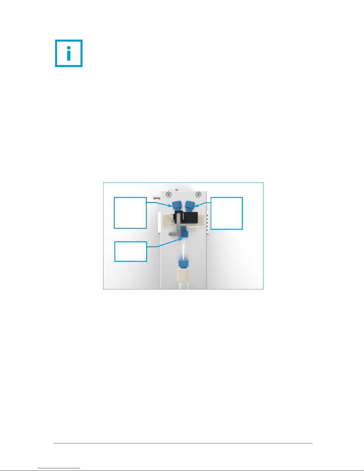
Connect tubes between the syringe holder and the valves as follows:
ATTE NT IO N. Before using the valve please check its chemical resistance against the
media you intend to pump.
Outlet
Intake

neMESYS Hardware Manual 41
6.4.3 Mounting the Blank Holder
The blank holder prevents the syringe from bending upward, which is an effect that occurs in case of
high pressure. As a consequence syringe wear is decreased as well. To mount the blank holder simply
place it into the two gaps on the device and fasten it on both sides with the provided screws (2 mm
Allen head).

42 neMESYS Hardware Manual
7 High Pressure Syringe Pump
7.1 Technical Data
7.1.1 Environment
OPERATING T EMPERA TURE
0°C to 45°C
STORAGE TEM PERATURE
-20°C to 75°C
OPERATING A IR HUMID ITY
20% to 90%, non-condensing
STORAGE AIR HUMIDITY
20% to 90%, non-condensing
7.1.2 Wetted Parts
SYRINGE HOL DER AND FI TTING
Stainless steel 1.4404 (316L)
PR ES SURE SEN SOR
Aluminium oxide (Al2O3)
PR ES SURE SEN SOR SEAL
Perfluoroelastomer FFKM

neMESYS Hardware Manual 43
7.1.3 Mechanical Data
DIME NS IONS (L X W X H)
310 x 110 x 136 mm
WEIGHT
≈4500 g
7.1.4 Electrical Data
SUPPLY VOLT AGE
24 VDC
CU RR ENT DRAI N
1,9 A
PO WE R CONSUM PTION
45 W
7.1.5 Interfaces
CA N
1 Mbit/s
RS-232
section 9
ACCE SS ORY PORT
section 8

44 neMESYS Hardware Manual
7.1.6 Dosing Performance
The following table provides an overview of minimum and maximum dosing speeds. The resulting flow
rates shown here are based on CETONI stainless steel syringes. Dosing precision slowly decreases below
the speeds and flow rates referred to as pulsation-free.
The table also indicates the maximum pressure that can be achieved with the High Pressure Syringe
Pump in combination with the respective syringe.
You need the nominal stroke and the maximum stroke for the software configuration of syringes. Please
read the relevant sections in the software and syringe manual.
SPEED
MIN
[µM/S]
MI N
PU LS ATION- FREE
[µM/S]
MA X [MM/S]
0,061
0,636
7,00
SYRINGE
NOMINAL /
MA X STROKE
[MM].
MA X.
PR ES SURE
FL OW RATES
MI N
[µL/MIN]
MI N
PU LS ATION- FREE
[µL/MIN]
MA X
[ML/S]
2,5 ML
49,99
60
510 bar
7400 psi
0,182
1,908
0,35
5 ML
52,85
60
270 bar
3900 psi
0,344
3,609
0,66
10 ML
49,89
60
120 bar
1740 psi
0,728
7,646
1,40
25 ML
50,86
60
50 bar
360 psi
1,785
18,751
3,44
50 ML
51,91
60
25 bar
360 psi
3,499
36,743
6,74
100 ML
50,89
60
12 bar
175 psi
7,137
74,960
13,76

neMESYS Hardware Manual 45
7.2 Transport and Storage
Please do not lift or transport the modules while they are plugged into each other. Transport in
assembled state is only permissible when using the original packaging.
Use the original packaging for shipping the modules. Please observe the information provided in 7.1.1
with respect to storage.
ATTE NT IO N. Danger of damaging the device. Do not transport modules while they are
plugged into each other.
7.3 Maintenance and Care
When used properly, the device is maintenance-free. In case of problems that you cannot fix yourself or
that require opening the device, please contact CETONI GmbH to coordinate any further actions. The
device may be opened only by CETONI GmbH or authorized service personnel. Failure to adhere to this
rule will void the warranty.
The software manual includes detailed information about malfunctions with respect to the operating
software.
Wipe the device with a moist (not wet) cloth in such way that no liquids get into the inside. In case of
heavy soiling you may use some detergent or alcohol.
7.4 Hardware Operation
Connect the High Pressure Syringe Pump to your base module / system as described in section 3.2.2
and the software manual. The High Pressure Syringe Pump only works with an installed safety hood and
may only be operated with it in place. Please refer to section 7.4.1 for more information about using the
safety hood.
If the module has not been configured, you will be required to perform a reference move during the
configuration process. During the reference move the piston holder will move to its front position and
be synchronized with the software display. To avoid damage the reference move may only be performed
without a syringe.

46 neMESYS Hardware Manual
After deactivating the base module the piston holder can be moved by applying some force (e.g.
through residual pressure in the system). Therefore, it is sensible to repeat the reference run from time
to time.
ATTE NT IO N. The reference move must be performed without a syringe. Otherwise the
device or the syringe may be damaged.
7.4.1 Mounting the Safety Hood
Place the safety hood on the device in such way that the pins slide into the gaps provided for them
(blue in image). Push down on the opposite end of the hood until the spring-loaded balls (also shown in
blue) settle into the holes provided for them in the hood. To remove the hood, simply reverse this
process.
CAUTION. Only use the High Pressure Syringe Pump with the mounted safety hood!
Do not touch any moving parts on the device during operation!
IMPO RT AN T. If you remove the safety hood during operation, the High Pressure
Syringe Pump will stop automatically.
Balls
Pins

neMESYS Hardware Manual 47
7.4.2 Fluidic Connections
A Swagelok® tube fitting is used for fluidic connection. It is suitable for using capillaries made from
metal (e.g. stainless steel, titanium) and plastic (e.g. PTFE, PEEK). Please refer to information provided by
the respective manufacturer with respect to maximum pressure.
The High Pressure Syringe Pump is supplied with two tube fittings for capillaries with an external
diameter of 1/16” and 1/18”.
Following is a description of using the tube fittings:
7. 4. 2. 1 FI RST-TI ME INSTALLATION
(1) Fully insert the tube / hose into the fitting and against the shoulder; rotate the nut finger-tight.
(2) Mark the nut at the 6 o’clock position.
(3) Tighten the nut three-quarters turn to the 3 o’clock position with an open-end wrench.
7. 4. 2. 2 DI SMAN TLIN G
ATTE NT IO N. Release pressure from the system before loosening the fittings.
(1) Before dismantling, draw a marker line across the nut and the fitting body. In this way you create
a reference for retightening the cap nut to exactly the same position it was in before.
(2) Pull out the capillaries. The nut and the ferrules remain on the capillary.
7. 4. 2. 3 RE AS SE MBLY
(1) To reassemble, insert the capillary with preassembled ferrules into the fitting body until the front
ferrule seats against the fitting body.
(2) Rotate the nut with open-end wrench to the previously pulled-up position as indicated by the
marks you made before; at this point you will feel a significant increase in resistance.
(3) Retighten the nut slightly. Done!
You can purchase additional connecting material from Swagelok, such as replacement clamping rings
(ordering number SS-100-SET).

48 neMESYS Hardware Manual
IMPO RT AN T. Only use capillaries specified for the anticipated pressure levels. The
supplied 1/16” PEEK tubes are suitable for pressures up to 200 bar.
ATTE NT IO N. After connecting, check the tightness of all fluidic connections on a
regular basis.
7. 4. 2. 4 RE PLAC IN G TH E CONDUIT FITTING
The tube fitting is screwed into the syringe holder and can be loosened or tightened with a 9/16” open
end wrench. For this purpose, place the wrench onto the large hexagon nut (not the small one of the
cap nut)!
There is a metal bushing behind the conduit fitting for sealing purposes. This bushing can remain in the
borehole while the conduit fitting is replaced.
Firmly tighten the newly mounted conduit fitting to achieve a sealed connection.

neMESYS Hardware Manual 49
7.4.3 Mounting a Syringe
Before mounting a syringe to the High Pressure Syringe Pump, it must be configured and selected in the
operating software. The respective process is described in the software manual. You will need the
volume (scale volume), the nominal stroke (scale length) and the maximum stroke (piston stroke), which
may be different.
The scale volume and scale length values are engraved on CETONI stainless steel syringes. Unless
otherwise stated, the piston stroke is 60 mm. These values can also be found in the table in section
7.1.6.
Additional information can be found in the syringe manual.
Follow these steps to mount a syringe on the High Pressure Syringe Pump:
To be able to screw the syringe into the mounting bore while establishing a sealed connection, please
insert one of the provided O-rings (3 mm inside diameter and 1.5 mm cord thickness) into the
indentation at the syringe outlet (blue in image).
Scale Length
Scale Volume

50 neMESYS Hardware Manual
Position the piston holder in such way as to make sufficient space to screw in the syringe. Remove the
safety hood as described in section 7.4.1. Screw the syringe into the syringe holder as far as it will go.
Put the safety hood back on the device and advance the piston holder until it touches the piston. Take
off the safety hood and attach the piston to the piston holder using the knurled screw.
O-ring

neMESYS Hardware Manual 51
After putting the safety hood back on, you are ready for dosing.
ATTE NT IO N. Before operation, check the resistance of the syringe seal against the
dosing medium. If necessary, replace the seal with a seal made from a different material.
IMPO RT AN T. Syringes, and particularly seals, are wear parts. Check them on a regular
basis and replace them if necessary.
7.4.4 Pressure Sensor
There is an integrated pressure sensor in the syringe holder of the High Pressure Syringe Pump. This
allows the device to stop automatically upon reaching the preset maximum pressure.
ATTE NT IO N. Before using the device, check the chemical resistance of wetted
materials against the fluid to be metered.

52 neMESYS Hardware Manual
The pressure sensor must be configured in the software before use. The associated process is described
in the software manual.
For the configuration you will need the pressure range of the sensor (e.g. 0 – 600 bar) and the range of
the output signal (e.g. 0.5 – 4.5 V). These values can be found on the nameplate on the side of the
device under sensor:
ATTE NT IO N. Configure the pressure sensor before use, to avoid damaging the device
or your application.

neMESYS Hardware Manual 53
8 Accessory Port
The Low, Mid and High Pressure Syringe Pumps, are equipped with an accessory port or can be
equipped with it as an optional extra. The additional port allows the use of a pressure sensor, for
example.
The pin assignment of the connector at the module and the wire colors of the connecting cable, which
can be purchased from CETONI, can be found in the table on the next page. Of course, you can also
purchase ready-made periphery devices from CETONI GmbH.
A matching connector plug is also available from Hirose (order number HR10A-10P-12P(73)).
The configuration of pressure sensors is described in the software manual. Read and observe the
relevant section before connecting a pressure sensor.
IMPO RT AN T. Pin 1 is not assigned at the accessory port of the High Pressure Syringe
Pump, because analogue input AI1 is already used for the built-in pressure sensor.

54 neMESYS Hardware Manual
PIN
SIGN AL
DESCRIPTION
1
Analog input AI1
0-5 V (to Pin 12)
2
Analog input AI2
0-5 V (to Pin 12)
3
Digital input 1
<0,8 V ≙ Low
>2 V ≙ High
24 V max.
4
Digital input 2
<0,8 V ≙ Low
>2 V ≙ High
24 V max.
5
Digital input 3
<1,7 V ≙ Low
>4,2 V ≙ High
24 V max.
6
Digital output 1
Valve voltage
NPN Max. 1 A
Active: 0 V (GND)
Inactive: open
7
Digital output 2
Switch valve
NPN Max. 1 A
Active: 0 V (GND)
Inactive: open
8
Digital output 3
NPN Max. 1 A
Active: 0 V (GND)
Inactive: open
9
Digital ground
10
+24 V Out
+24 VDC / <1 A
11
+5 V Out
+5 VDC / <150 mA
12
Analog ground

neMESYS Hardware Manual 55
9 RS232 Connection
9.1 Pin Assignment of Module Interfaces
PL UG
SOCKET
PIN
1
Not connected
RS232 RX
2
Not connected
RS232 TX
3
CAN High
CAN High
4
CAN Low
CAN Low
5
Signal GND
Signal GND
A1
+24 V
+24 V
A2
GND
GND
9.2 OEM RS232 Cable Set
9.2.1 RS232 Wiring
Insert the mixed D-Sub plug of the cable into the socket of the final module. The system should be
deactivated when you do this. Tighten both screws on the plug manually. You do not need a bus
termination plug, since the plug of the RS232 cable already contains a bus termination resistor.
Now, plug the 9-pin D-Sub socket of the cable into an RS232 connection on your PC or other controller.
For greater distances to the socket please use a 1:1 cable with a 9-pin D-Sub plug.
A1
1
2
A2
3 4 5
A1 1 2
A2
3
4
5

56 neMESYS Hardware Manual
Now, you can reactivate your system and send or receive data through RS232. Since every module
contains a gateway from RS232 to the system’s internal CAN bus, you can now address each module of
your system with only one RS232 cable.
9.2.2 Communication Settings
For a functioning communication with the neMESYS modules you have to make the following
communication settings for the serial interface on your PC or other controller:
Baud rate: 115200
Data bit rate: 8
Parity: none
Stop bits: 1
Flow control: none
9.2.3 Pin Assignment of the RS232 Cable
The OEM RS232 cable adapts the neMESYS device interface to a standard 9-pin D-Sub plug. The
following table shows the pin assignment of the neMESYS interface and the 9-pin D-Sub:
neMESYS Interface (socket)
9-pin D-Sub socket
Pin Cable
Pin
1
RS232 RX
Orange 3 TXD Transmit Data
2
RS232 TX
Brown 2 RXD Receive Data
5
Signal GND
Black 5 GND Signal GND
D-Sub housing = shielding
Shielding
1 2 3
4
5 9 8
7 6 A1 1 2
A2
3 4 5

neMESYS Hardware Manual 57
10 Disposal
Please send your old devices back to CETONI GmbH. We will take care of proper disposal according to
electric devices regulations.
If necessary, please decontaminate the device before sending it back and attach a completed
decontamination declaration with your shipment.
 Loading...