

Page 1
DOC-1560 Rev 2019-10-17
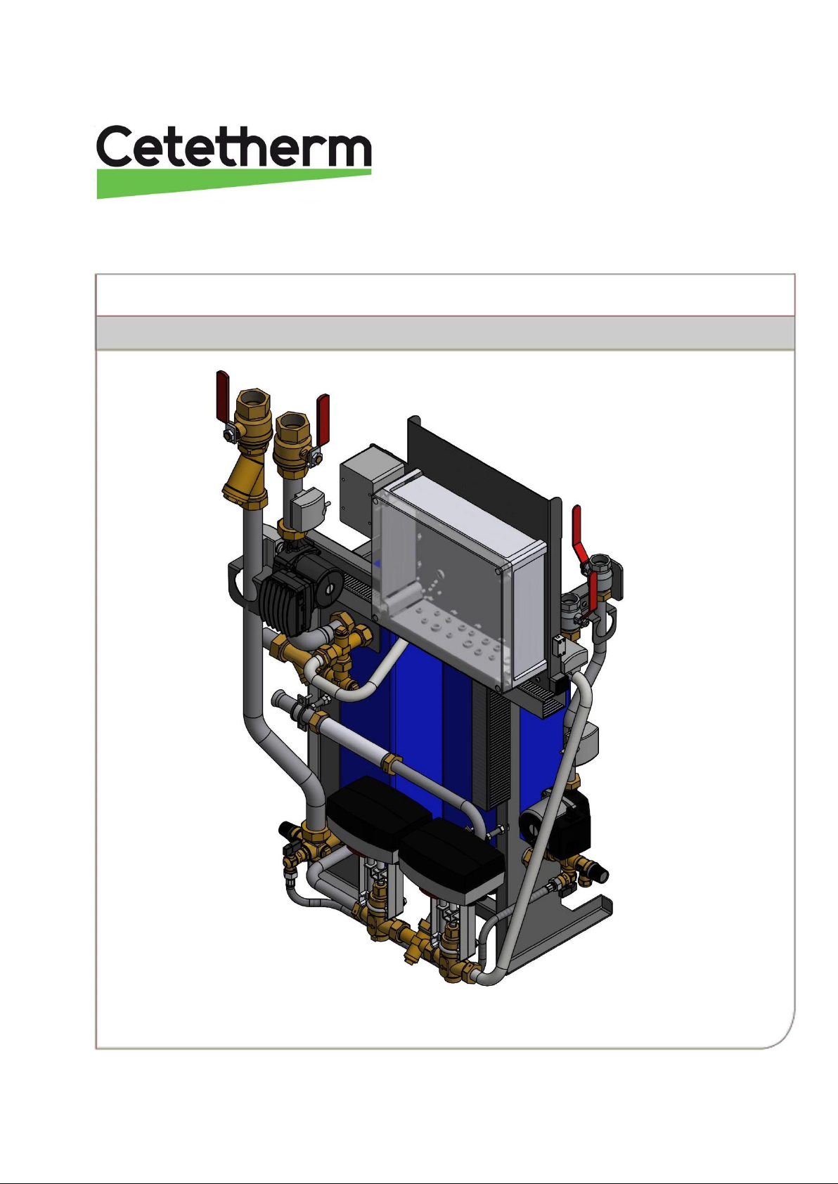
Installation, service and operating instruction Cetetherm Midi Wall IQHeat
Heating and domestic hot water substation for apartment houses (10-30 apts.)
Page 2
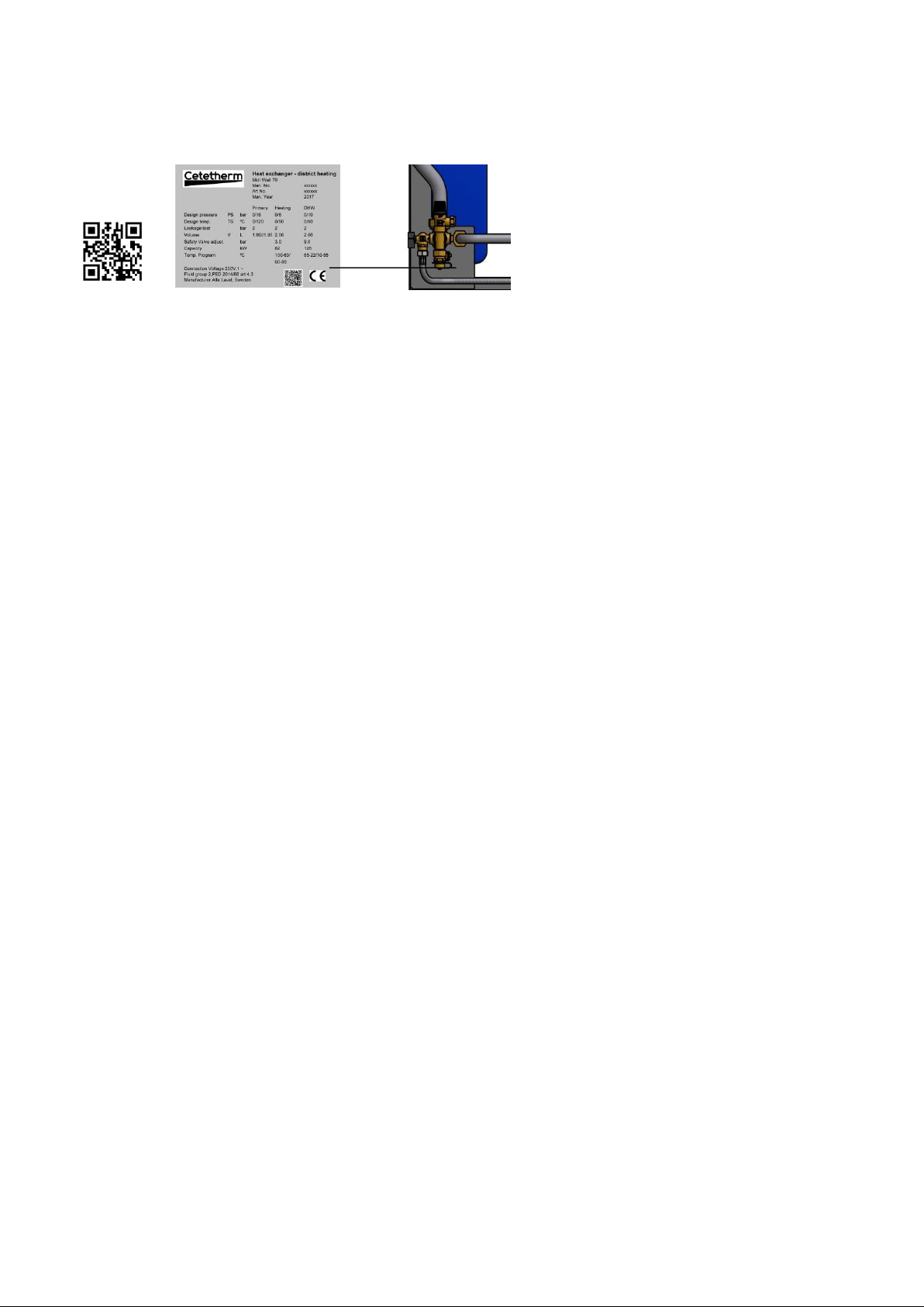
This manual is published by Cetetherm.
Cetetherm can without further notice make changes and improvements to the content in this manual if it is necessary due to printing
mistakes, wrong information or changes in the hardware or software.
All these types of changes will be included in future release of the manual.
For additional online information and manual:
QR-code:
Page 3

Cetetherm Midi Wall IQHeat
Installation, service and operating instruction
1
Contents
1 General .................................................................................................................................. 3
1.1 Comfort ......................................................................................................................................................3
1.2 Installation .................................................................................................................................................3
1.3 Long-term security .....................................................................................................................................3
1.4 CE-marking ................................................................................................................................................3
1.5 Information about the document ................................................................................................................3
1.6 General warnings ......................................................................................................................................4
1.7 Product overview Midi Wall .......................................................................................................................5
2 Operating instructions .......................................................................................................... 6
2.1 Operation ...................................................................................................................................................6
2.2 Safety equipment/inspection .....................................................................................................................6
3 Installation ............................................................................................................................. 7
3.1 Unpacking ..................................................................................................................................................7
3.2 Preparation ................................................................................................................................................7
3.3 Mounting ....................................................................................................................................................7
3.4 Mounting the options .................................................................................................................................8
3.5 Adjustments and settings for start up ........................................................................................................8
3.6 Dismantlement...........................................................................................................................................8
3.7 Commissioning advice ..............................................................................................................................8
3.8 Connection overview .................................................................................................................................9
3.9 Measure sketch Midi Wall IQHeat .......................................................................................................... 10
4 Control center IQHeat ......................................................................................................... 11
4.1 Password and login ................................................................................................................................ 12
4.1.1 Log in ................................................................................................................................................. 13
4.2 Time functions setting of time and date ................................................................................................. 13
4.2.1 Reading date and time ...................................................................................................................... 13
4.2.2 Setting date and time ........................................................................................................................ 13
5 Troubleshooting .................................................................................................................. 14
5.1 Fault indication for IQHeat ...................................................................................................................... 14
6 Electrical installation .......................................................................................................... 15
6.1 General ................................................................................................................................................... 15
6.2 Connection to internet ............................................................................................................................ 15
6.3 Installation of outdoor temperature sensor ............................................................................................. 15
6.4 Electrical circuit diagram ........................................................................................................................ 16
7 Schematic diagram, main components ............................................................................. 17
7.1 Option 3-point HB metering .................................................................................................................... 17
8 Pump settings and capacity ............................................................................................... 18
8.1 General ................................................................................................................................................... 18
8.2 DHWC pump Grundfos UPSO 15-55, capacity ...................................................................................... 18
8.3 Heating circuit pump Grundfos UPMXL 25-125 180 Auto (GFJOC), settings and capacity .................. 19
8.3.1 Changing pump curve setting ........................................................................................................... 20
8.4 Heating circuit pump Grundfos Magna3 25-100, capacity ..................................................................... 21
9 Service instructions ............................................................................................................ 22
9.1 Tap water, service instructions ............................................................................................................... 22
9.1.1 Tap water too cold ............................................................................................................................. 22
9.1.2 Tap water too warm ........................................................................................................................... 22
9.1.3 Hot water temperature unstable ........................................................................................................ 22
9.1.4 Nosie in the DHWC system ............................................................................................................... 23
9.2 Heating system, service instruction ........................................................................................................ 23
9.2.1 Heating system temperature too high or too low .............................................................................. 23
9.2.2 No heating ......................................................................................................................................... 23
9.2.3 Noise in the radiator system .............................................................................................................. 24
9.2.4 Heating temperature unstable ........................................................................................................... 24
9.2.5 Heating system often needs topping up ............................................................................................ 24
Page 4

Cetetherm Midi Wall IQHeat
Installation, service and operating instruction
2
10 Service actions for the installer ......................................................................................... 25
10.1 Check if the district heating strainer is blocked ...................................................................................... 25
10.2 Check the function of the heating and hot water valve and actuator ..................................................... 26
10.3 Check heating circuit strainer ................................................................................................................. 27
10.4 Check DHWC pump ............................................................................................................................... 27
10.5 Run the pump manually ......................................................................................................................... 28
10.6 Check the volume take-up and pressure equalizing of the expansion vessel ....................................... 28
11 Maintenance and repairs .................................................................................................... 29
11.1 Change the pumps ................................................................................................................................. 29
11.2 Change the heating and hot water actuator ........................................................................................... 30
11.3 Change the heating or hot water valve .................................................................................................. 30
11.4 Change the temperature sensor heating supply/return .......................................................................... 31
11.5 Change the outdoor temperature sensor ............................................................................................... 31
11.6 Change the expansion vessel ................................................................................................................ 31
12 Options ................................................................................................................................ 32
12.1 3-point HB metering ............................................................................................................................... 32
12.2 Mounting floor stand ............................................................................................................................... 32
12.3 Balancing valve DHWC .......................................................................................................................... 33
13 Technical data and performance ....................................................................................... 35
13.1 Operation data Midi Wall 70 ................................................................................................................... 35
13.2 Operation data Midi Wall 100 ................................................................................................................. 36
13.3 Operation data Midi Wall 130 ................................................................................................................. 37
13.4 Technical data ........................................................................................................................................ 37
Page 5

Cetetherm Midi Wall IQHeat
Installation, service and operating instruction
3
1 General
Cetetherm Midi Wall is a complete, ready-to-install heating network substation for heating and hot water. It is
designed for buildings with a primary connection to a heating network. Cetetherm has years of experience in
heating network technology and has developed Midi Wall with well-planned pipe work and with all components
easily accessible for inspection and possible future servicing.
1.1 Comfort
Midi Wall has fully-automatic temperature control for heating and hot water. The heating is controlled in relation
to outdoor temperature and/or desired room temperature. The hot water is controlled and maintained at the
desired temperature.
1.2 Installation
Well planned pipe work and readymade electrical wiring make installation very simple. A pre-programmed
controller and plug-and-socket connection provide further simplification, so that the substation can be started
without delay. The Midi Wall is designed for hanging on the wall.
Before installation this manual must be read.
1.3 Long-term security
All components are adjusted together and undergo thorough function testing in accordance with ISO 9001:2008
quality assurance system. For future servicing requirements, all components are easily accessible and
individually replaceable.
1.4 CE-marking
Midi Wall is CE-marked to certify that the substation conforms to international safety regulations. To maintain
the validity of the CE marking, only identical replacement parts must be used.
1.5 Information about the document
All pictures in this document are general images.
Mid Wall is available in different models and levels of equipment.
Page 6
Cetetherm Midi Wall IQHeat
Installation, service and operating instruction
4
1.6 General warnings
The installation work must be carried out by an authorized installation contractor. Before the system
is taken into operation, it must be pressure tested in accordance with relevant regulations.
The temperature and the pressure of the district heating water are very high. Only qualified
technicians can work with the district heating substation. Incorrect operation may cause serious
personal injury and result in damage to the building.
If the hot water temperature is set too high, people may be scalded. If the hot water temperature is
set too low, unwanted bacteriological growth may occur in the hot water system. This can result in
serious personal injury.
Parts of the Midi Wall may get very hot and should not be touched.
Before the substation is connected to the electrical supply, make sure that the secondary heating
system is topped up with water. Starting up the system without water will damage the circulation
pump.
The substation comes prepared with an electrical plug to be connected to the main supply. The
strain relief clips of the cable must be fitted so that there is no risk of damage. If necessary, the
plug-and-socket connection can be replaced with a permanent installation with an all-pole isolate
switch. This must be carried out by a qualified electrician.
When starting up the district heating substation: to avoid the risk of scalding, make sure that no-one
draws any hot water until the hot water temperature has been adjusted.
Start district heating circulation by first opening the valve in the district heating supply and then
return lines, to avoid pollutions in the system. Open the valves slowly to avoid pressure surges. Do
the same way with the heating circuit, first open the valve for heating supply then return.
Do not shut of the electrical supply to the operator control panel. This will damage the circulation
pump, valves, actuators etc.
The heating station should be placed in a locked space, non-accessible for unauthorized personnel.
Page 7
Cetetherm Midi Wall IQHeat
Installation, service and operating instruction
5
1.7 Product overview Midi Wall
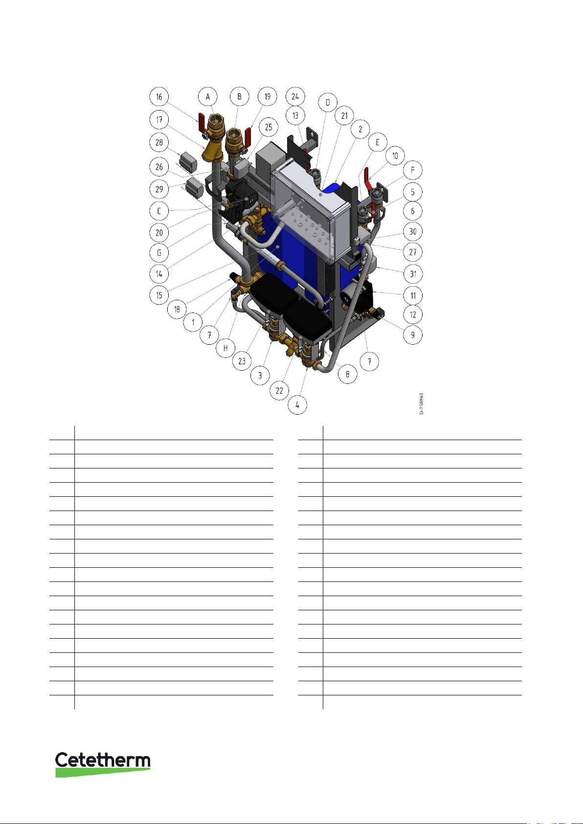
Picture 1
1.
Heat exchanger, heating
21.
Control centre
2.
Heat exchanger, DHW
22.
Actuator, DHW
3.
Control valve, heating
23.
Actuator, heating
4.
Control valve, DHW
24.
Temperature sensor, DHW
5.
Shutoff valve, cold water
25.
Temperature sensor, heating supply
6.
Check valve, cold water
26.
Temperature sensor, heating return
7.
Filling valve
27.
Temperature sensor, outdoor
8.
Hose
28.
Temperature sensor, district heating supply
9.
Safety valve, cold water
29.
Temperature sensor, district heating return
10.
Shutoff valve, DHWC
30.
Temperature sensor, primary heating return
11.
Pump, DHWC
31.
Temperature sensor, DHWC
12.
Non-return valve, DHWC
A.
Heating return
13.
Shutoff valve, DHW
B.
Heating supply
14.
Strainer, primary in
C.
District heating supply
15.
Dummy, heat meter
D.
DHW
16.
Shutoff valve, heating return
E.
CW
17.
Strainer, heating return
F.
DHWC
18.
Safety valve, heating
G.
District heating return
19.
Shutoff valve, heat supply
H.
Connection expansion vessel
20.
Pump, heating
Page 8

Cetetherm Midi Wall IQHeat
Installation, service and operating instruction
6
2 Operating instructions
2.1 Operation
The temperature and pressure of the incoming heating network water from the culvert network are very high.
For this reason, only the heat from this water is used. The heating network water does not enter the heating
and hot water systems of the building.
The heat from the heating network water is transferred to the heating and hot water systems of the building in
the heat exchangers. The heat is transferred through thin plates of acid-resistant stainless steel which keep the
heating network water separate from the systems in the building.
Midi Wall has automatic temperature control for heating and hot water. The heating circuit is controlled in
relation to outdoor temperature and/or desired room temperature by means of a controller and temperature
sensor. When no heat is needed, the circulation pump in the heating circuit stops automatically, but is started
regularly to make sure that it does not seize up during long idle periods. The hot water temperature is controlled
by a temperature control system which is set to about 55 ºC.
After adjustment, the Midi Wall operates completely automatically. However, in hard water areas it is advisable
to be attentive and to remedy any faults in good time if the temperature of the hot water is too high; otherwise
the risk of lime deposits in the heat exchanger may increase.
2.2 Safety equipment/inspection
• Daily inspection to check for leaks from pipes or components.
• Weekly inspection to make sure that the operation of the heating and hot water control systems is
stable and that the temperature does not fluctuate. Temperature hunting causes unnecessary wear of
valves, actuators and heat exchangers.
• Every three months check the safety valves and the pressure in the heating system.
To check the operation of a safety valve, turn its wheel/knob until water escapes from the valve, then close the
wheel/knob quickly. Occasionally a safety valve may open automatically to release excess pressure. After a
safety valve has been open it is important that it closes properly and does not drip.
Hot water temperature in apartments or one family houses can be set to about 55°C. If the temperature is set
too high, there is a risk of scalding. Setting the hot water temperature too low may result in unwanted
bacteriological growth in the hot water system.
For setting and (if necessary) fine adjustment of the heating and hot water temperatures,
see User instruction IQHeat Doc-1552.
The heating system is topped up via the topping up valve. Be sure to close the valve when the correct pressure
is reached. The water used to top up the system contains oxygen and may cause corrosion in the system. For
this reason, the system should be topped up as seldom as possible, at most once
If a joining must be loosened and then re-installed, for example when installing the substation or when
replacing a filter unit, the joining gaskets should be exchanged to prevent leaks.
Page 9

Cetetherm Midi Wall IQHeat
Installation, service and operating instruction
7
3 Installation
3.1 Unpacking
• Remove the transport packaging and check that the product has not been damaged in transit and that
the consignment agrees with the specifications.
• When lifting the unit, take care not to apply stress to pipes and heat exchangers as this may weaken
them Lift the unit in the frame; avoid lifting the unit by holding the heat exchangers. Use pallet lift where
applicable, if using back straps these should be attached to the substructure of the substation.
NOTE: Risk of injury lifting heavy objects.
3.2 Preparation
• Choose a suitable installation area in accordance with official regulations.
The system may generate sounds during operation caused by pumps, regulators systems, flows etc.
This should be taken into consideration during installation of the unit, so that possible operational
sounds affect the surroundings as little as possible. This means that the system should be installed on
well-insulated walls, such as outer walls or on concrete walls.
• Check the applicable regulations of the district heating supplier. The available differential pressure
should be at least 100 kPa and at most 600 kPa. Where the differential pressure is higher, a differential
pressure controller should be added to the installation.
• Flush heating and hot water systems.
3.3 Mounting
• Mount the substation on a wall with screws and bolts suitable for mounting wall material and substation
weight. The distance between floor and screw bracket should be 1420 mm. Note that distance between
screws are 400 mm. Mount the floor support on the central, use the middle mounting hole. Raise the
central and mount it on the wall.
• Place the substation so that connections, adjustment equipment and safety valves are easily
accessible.
• Mount the shutoff valves on district heating supply and return. Shutoff valves are not supplied.
• Connect the pipe works to the connection points, see 3.8 Connection overview.
• When executing hot work on or close by the substation, all incendiary components should be
demounted and removed.
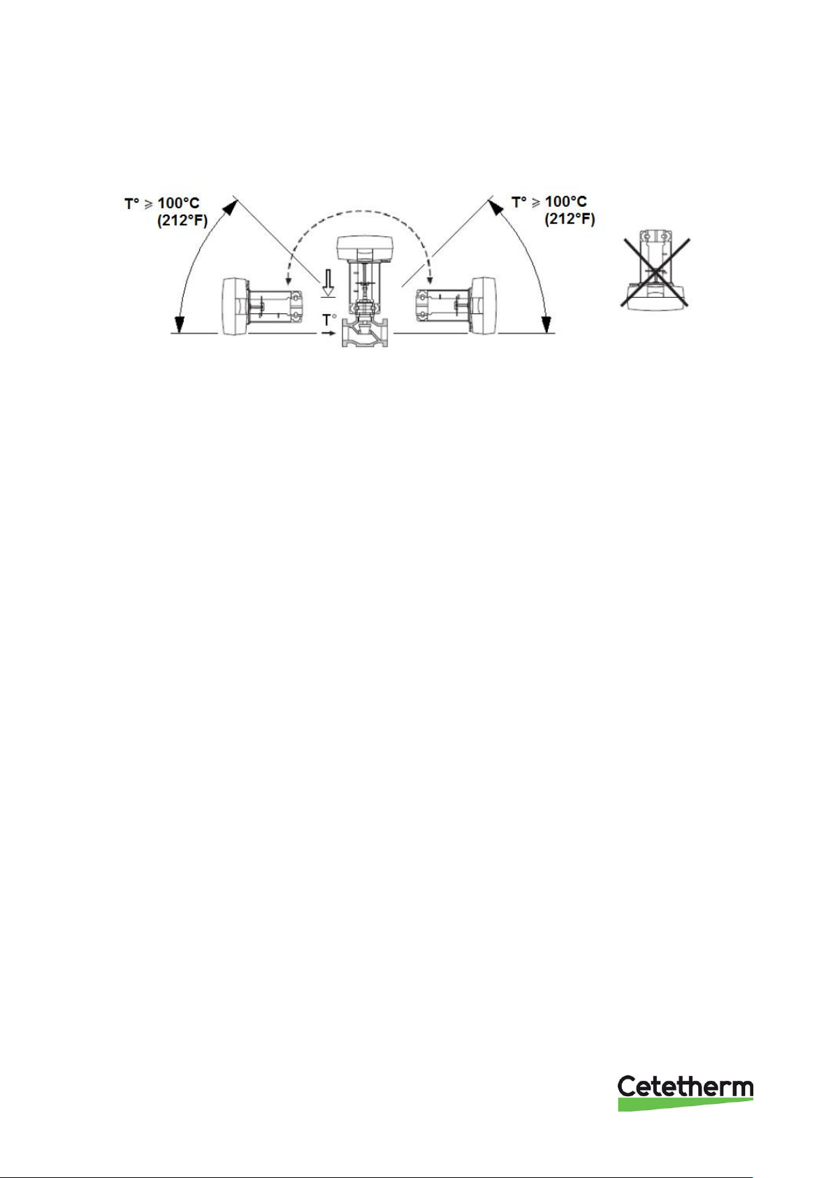
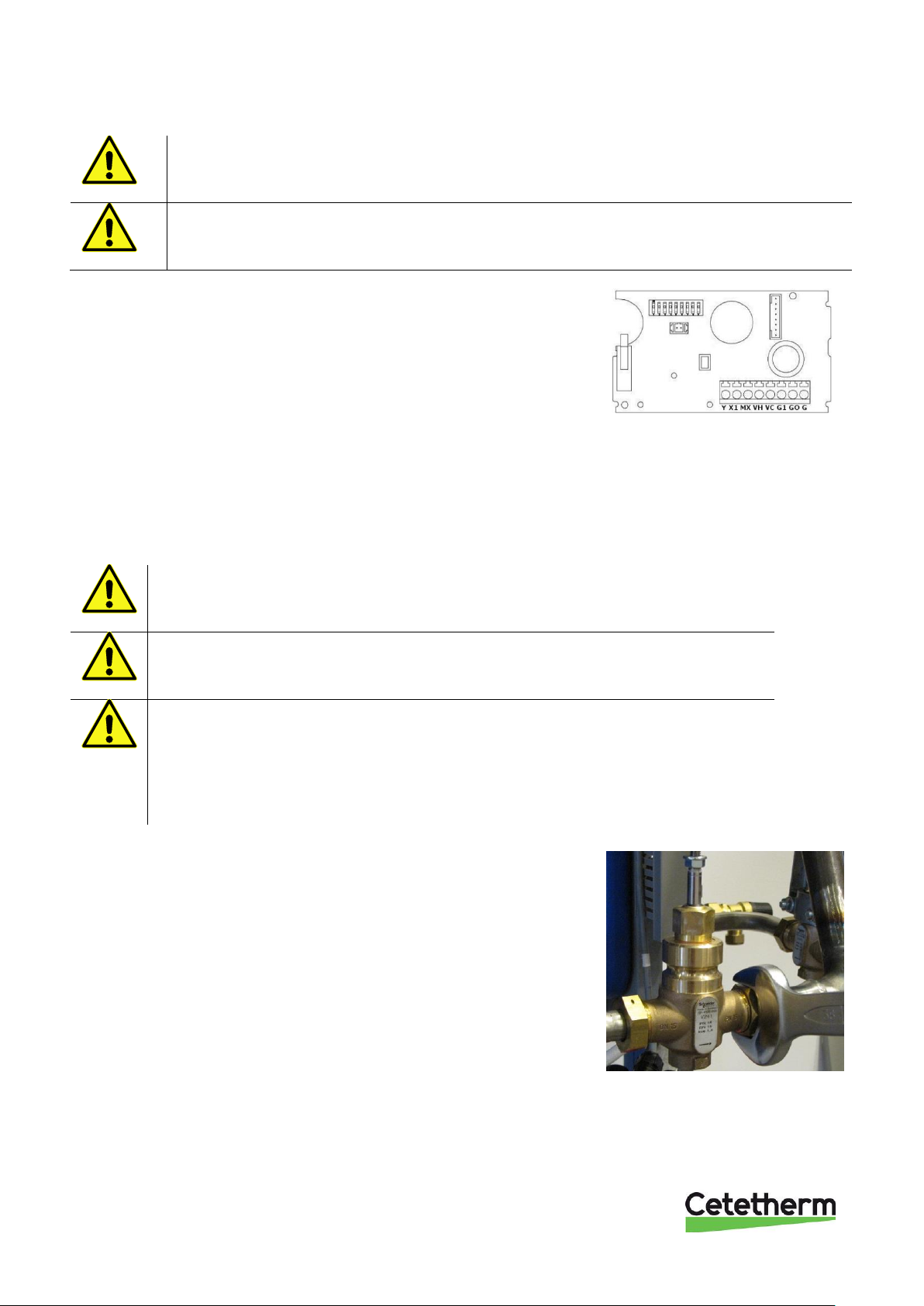
• With supply temperatures above 100°, it is recommended that the actuator is tilted or closed down, see
Picture 2.
• Take rules and instructions regarding hot work into account.
• Connecting pipes shall be suspended so that their weight does not stress the unit.
• All connecting pipes within and connecting to the units’ system shall be insulated according to
standards and regulations.
• Drainage pipes from safety valves must be taken to floor gully.
• Energy meters must be installed at a prepared location, replacing a gauge block, or following the
instructions of the energy supplier.
NOTE: the connection pipe between the valves is just for draining.
• Retighten all connections, including those made at the factory. If connections need retightening after
the installation has been taken into service, the system should be depressurised before retightening. If
the system is not depressurised before retightening, gaskets will be damaged.
• Required expansion volume shall be installed and provided with adequate pre-charge before start up.
• Remount plugs in drain valves after possible draining of circuit.
Page 10
Cetetherm Midi Wall IQHeat
Installation, service and operating instruction
8
• Mount the outdoor temperature sensor on the north side of the building, 2 metres above the ground, or
higher. For installation of the outdoor temperature sensor, see 6.3 Installation of outdoor temperature
sensor.
Picture 2
3.4 Mounting the options
• If the substation shall be provided with a 3-point HB metering, see mounting instructions
12.1 3-point HB metering.
• If the substation shall be provided with a floor stand, see mounting instructions
12.2 Mounting floor stand.
3.5 Adjustments and settings for start up
• Open incoming cold water supply and fill the service water and heating circuits, bleeding off any
trapped air.
• Check the operation and opening pressures of the safety valves.
• Adjust the hot water temperature by having a hot water tap open at normal flow rate for a time.
Measure the temperature at the draw-off point with a thermometer. The temperature should be
approximately 55°C. It takes about 20 seconds to get stable tap water temperature. See
troubleshooting chart for adjusting hot water temperature.
NOTE: Make sure that no cold water is mixed with hot water while making this adjustment.
• Start the heating circulation pump at the strongest flow setting during some minutes. The pressure
should be at least 100 kPa during winter and at least 60 kPa during summer.
• Set the pump capacity of the heating circulation pump according to chapter 8, Pump settings and
capacity. Use the lowest setting that manages the heating demand for best electrical efficiency
Make any necessary adjustment of the heating curve of the control and regulating equipment.
Information about the controller can be found in this document.
• Set time, date and hot water temperature on the adjustment center.
• The property owner must be informed on how to operate, adjust and maintain the unit. It is overly
important to inform about the safety systems and the risks associated with the high pressure and
temperature of the district heating systems water supply.
3.6 Dismantlement
When the time comes for the substation to be dismantled and scrapped it must be disposed of in the correct
manner in accordance with local or national regulations.
3.7 Commissioning advice
The controller has been set at the factory. If any function needs tuning, values can be changed with reference
to this manual for parameter setting. Initially, the commissioning process should be carried out with the factory
settings. The parameter settings need tuning only if the district heat terminal does not function accordingly.
Page 11
Cetetherm Midi Wall IQHeat
Installation, service and operating instruction
9
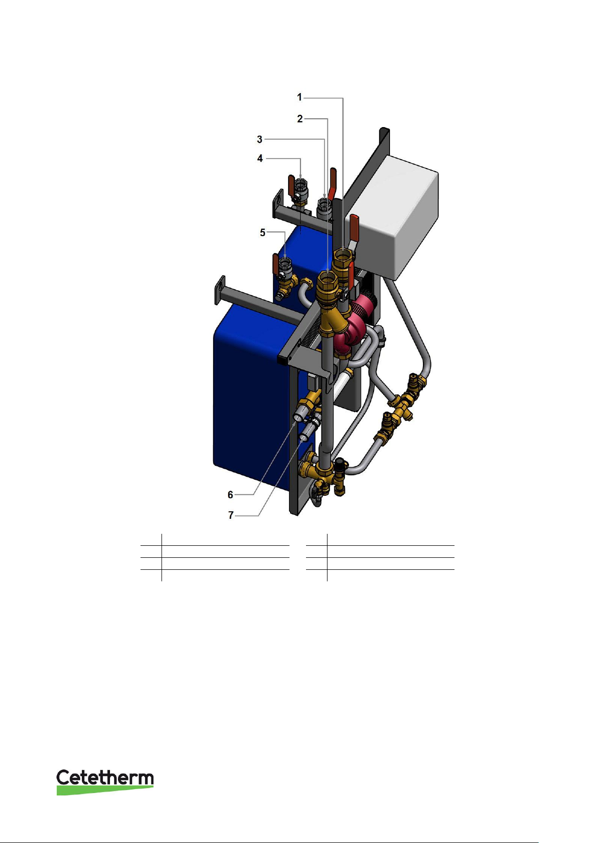
3.8 Connection overview
Picture 3
1
Heat Supply G1 1/4"
5 DHW G1”
2
Heat Return G1 1/4”
6 DH Supply DN25, weld
3
CW G1”
7 DH Return DN255, weld
4
VVC G1”
Page 12
Cetetherm Midi Wall IQHeat
Installation, service and operating instruction
10
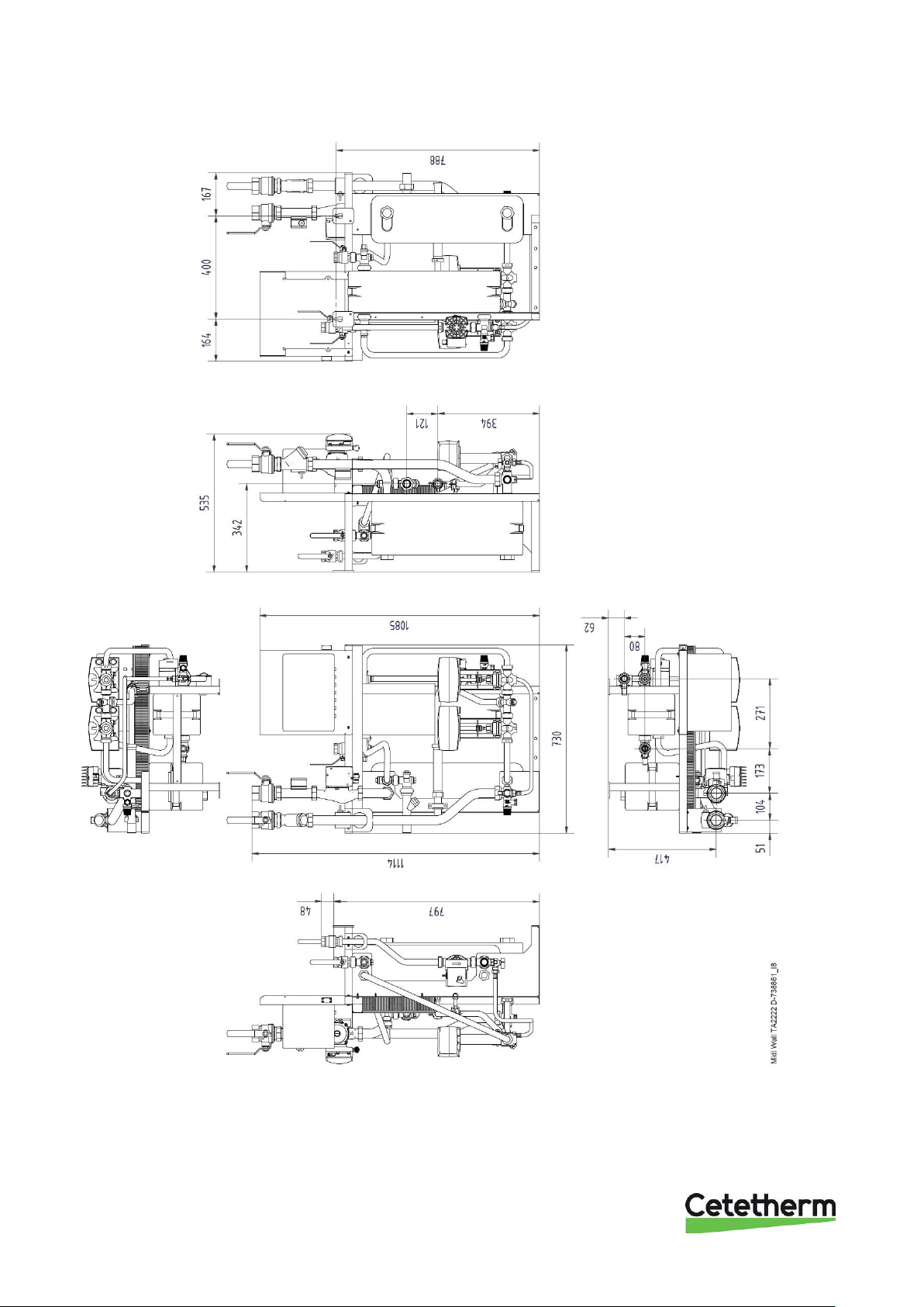
3.9 Measure sketch Midi Wall IQHeat
Picture 4
Page 13

Cetetherm Midi Wall IQHeat
Installation, service and operating instruction
11
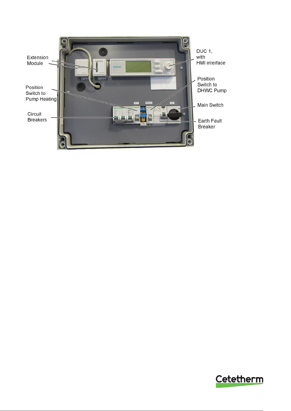
4 Control center IQHeat
IQHeat is an intelligent controller for district heating and cooling substations.
Whether it is energy saving, energy cost reduction or comfort monitoring that is the goal, IQHeat from
Cetetherm is an excellent choice.
IQHeat is fitted with a display.
IQHeat has always a temperature sensor on the primary side supply and return, and on the secondary side
supply and return. The sensors allow for the effective limitation of return temperatures and simple monitoring
and remote troubleshooting of functional or comfort problems.
IQHeat is always factory tested and factory set.
Midi Wall can be equipped with different IQHeat models:
• IQHeat50: serves one heating circuit
• IQHeat100: serves one heating circuit and one hot water circuit
Communication with the processing unit takes place with ModBus or TCP/IP.
Different methods of communication are available, depending on the external communication modules that are
connected.
The following add-on modules are available as options and can be connected to a Midi Wall:
• MBus
• BacNet IP
• Advanced Web
Add-on modules give you the option of
• meter data via MBus
• Integrated WEB server where all data and history from IQHeat is available through a simple web
browser without requiring any special software or server connections
• BacNet and LON as well as ModBus give you the option of controlling IQHeat from the central building
automation system.
For more information about the IQHeat please see User instruction IQHeat Doc-1552.
This manual describes all the services, functions and settings that can be made with the processing unit, which
is common to all models of IQHeat.
Not all the services, functions and settings are utilised by the different models.
Page 14
Cetetherm Midi Wall IQHeat
Installation, service and operating instruction
12
4.1 Password and login
The controller has password protection, allowing access to different menus.
The following log-in levels are available:
All users: no log-in, no password required
• read access to all menus except the system parameters, configuration and detail menus
• read access to alarm lists and alarm history
End user, level 6, password 1000
• appears with one key in the upper left corner of the display
• all rights as for in "all users"
• read access to all menus except configuration menus
• write access to the main set points (Setpoints/Settings. > Setpoints)
• alarms and alarm history can be acknowledged and reset
Service level, level 4, password 2000
Used for configuring I/Os and system settings. Only qualified service personnel should make changes at this
level.
• appears with two keys in the upper left corner of the display
• all rights as for "End users"
• access to all menus except I/O configuration and system settings
OEM, level 2
• appears with three keys in the upper left corner of the display
• all rights as for System Administrator
• access to all menus and system settings.
Contact Cetetherm if there is a need to change anything at this level.
Page 15
Cetetherm Midi Wall IQHeat
Installation, service and operating instruction
13
4.1.1 Log in
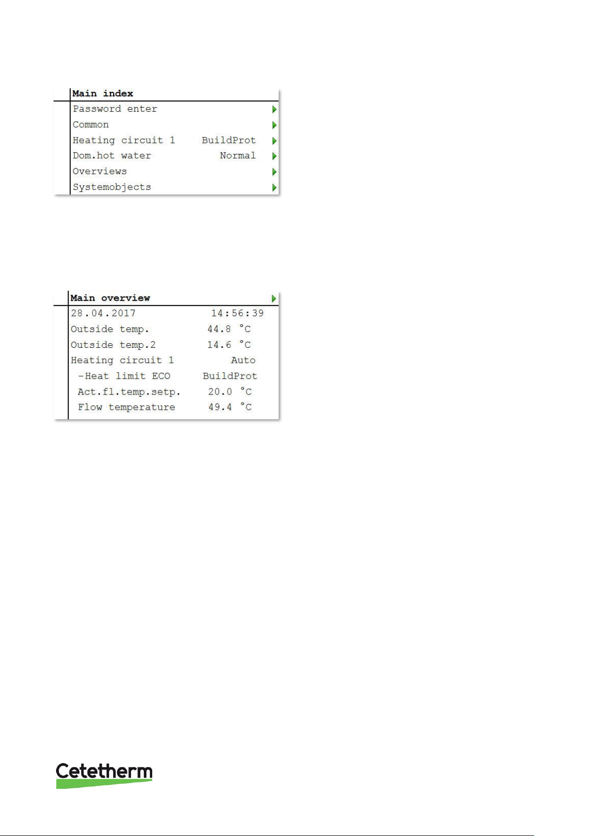
1. Keep the OK button pressed to access the
Password menu.
2. The first digit of four is marked with 0.
3. Turn the navigation dial until the desired number
appears.
4. Press OK to proceed to the next digit, continue
until all four are entered correctly and press OK.
The current key symbol will appear in the upper left
corner of the display window.
4.2 Time functions setting of time and date
The controller's clock includes the functions for summer and winter time changes and leap years. The clock has
a backup function to cover at least 24 hours of power cuts.
4.2.1 Reading date and time
1. Press Info to access Main overview.
2. The top line shows the set date and time.
4.2.2 Setting date and time
Requires login at end user level.
1. Press Info until the page with the date and time are displayed.
2. Move the cursor to the line for date and time.
3. Press OK to edit the day.
4. Set the correct day with the navigation dial, press OK to confirm and continue to edit the month and
year.
5. Continue to edit the hours, minutes and seconds in the same way.
6. Exit the menu with ESC.
Page 16

Cetetherm Midi Wall IQHeat
Installation, service and operating instruction
14
5 Troubleshooting
5.1 Fault indication for IQHeat
The processing unit alerts for different situations. Alarms are indicated on the control display with the alarm
symbol .
Alarms are divided into three classes:
• A or 1 = Alarm, High
• B or 2 = Alarm, Low
• C or 3 = Alarm, Warning
Active alarms:
• alarm symbol in the display flashes
• alarm button on the control panel flashes
Acknowledged but still active alarm:
• alarm symbol in the display lights
• alarm button on the control panel lights
If a GSM modem is connected to the processing unit, an alarm is sent by text message to the specified
telephone number.
For more information please see User instruction IQHeat Doc-1552.
Page 17
Cetetherm Midi Wall IQHeat
Installation, service and operating instruction
15
6 Electrical installation
6.1 General
The wiring in Midi Wall conforms to the applicable rules for CE marking and has undergone electrical safety
testing and function testing. For permanent installation must the substation be connected to an all-pole isolator
switch. This must be done by a duly qualified electrician.
The substation must be connected to a grounded power outlet.
6.2 Connection to internet
For connection to internet the control panel has a cable with RJ45-contact.
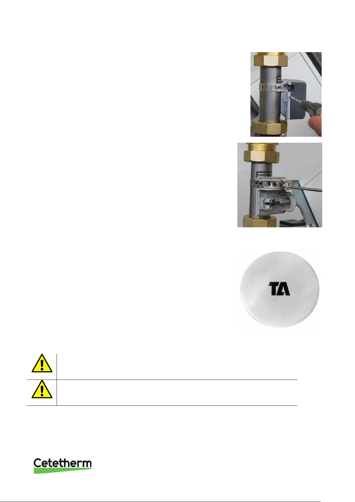
6.3 Installation of outdoor temperature sensor
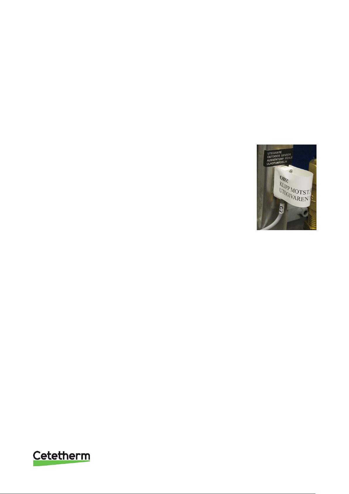
Connect the outdoor temperature sensor to a terminal strip in accordance with the
electrical diagram, if there is a resistor, remove it.
The resistor simulates an outdoor temperature of 0°C.
If using a cable with two conductor area of 0.75mm2 the maximum cable length is
80 meters.
Picture 5
Page 18
Cetetherm Midi Wall IQHeat
Installation, service and operating instruction
16
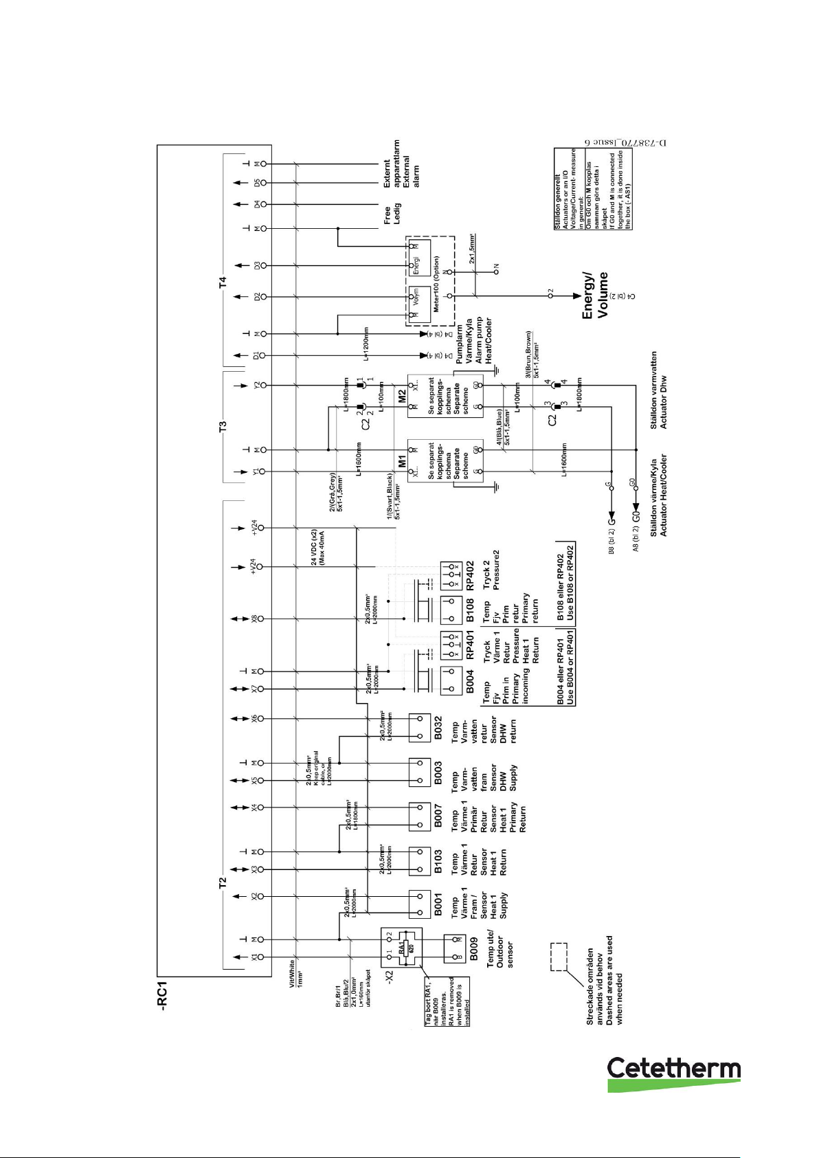
6.4 Electrical circuit diagram
Picture 6
Page 19
Cetetherm Midi Wall IQHeat
Installation, service and operating instruction
17
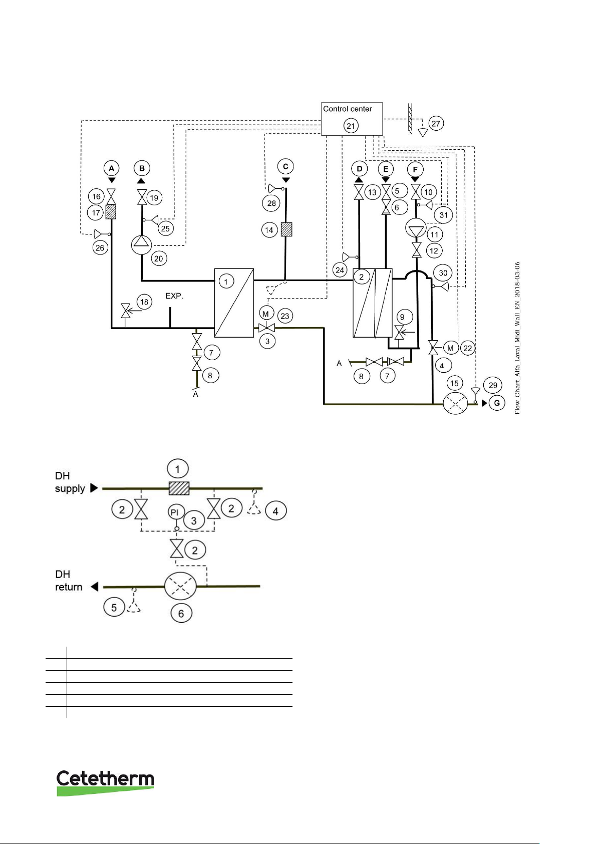
7 Schematic diagram, main components
Picture 7
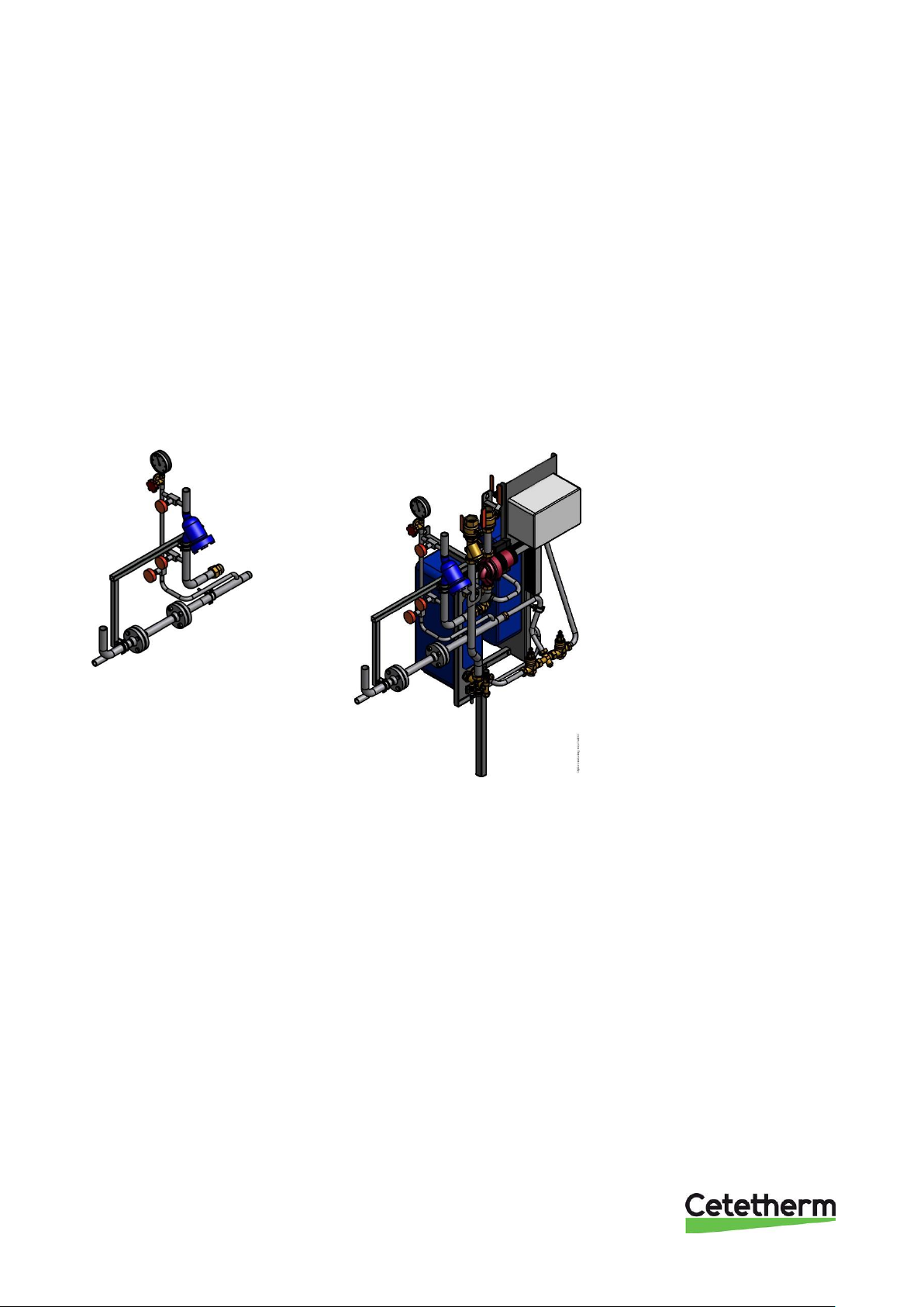
7.1 Option 3-point HB metering
Picture 8
1.
Welded filter
2.
Shut off valves
3.
Manometer clock
4.
Sensor pocket energy meter primary in
5.
Sensor pocket energy meter primary out
6.
Flanged dummy 260mm energy meter
Page 20
Cetetherm Midi Wall IQHeat
Installation, service and operating instruction
18
8 Pump settings and capacity
8.1 General
Mini Wall is equipped with two circulation pumps, one for the hot water circulation, DHWC-pump, and one for
the heating circuit.
The DHWC pump is a traditional three speed circulation pump. The DHWC pump has a switch where the
speed/capacity can be set.
The heating circuit can be equipped with two different circulation pumps, both pumps are pressure controlled.
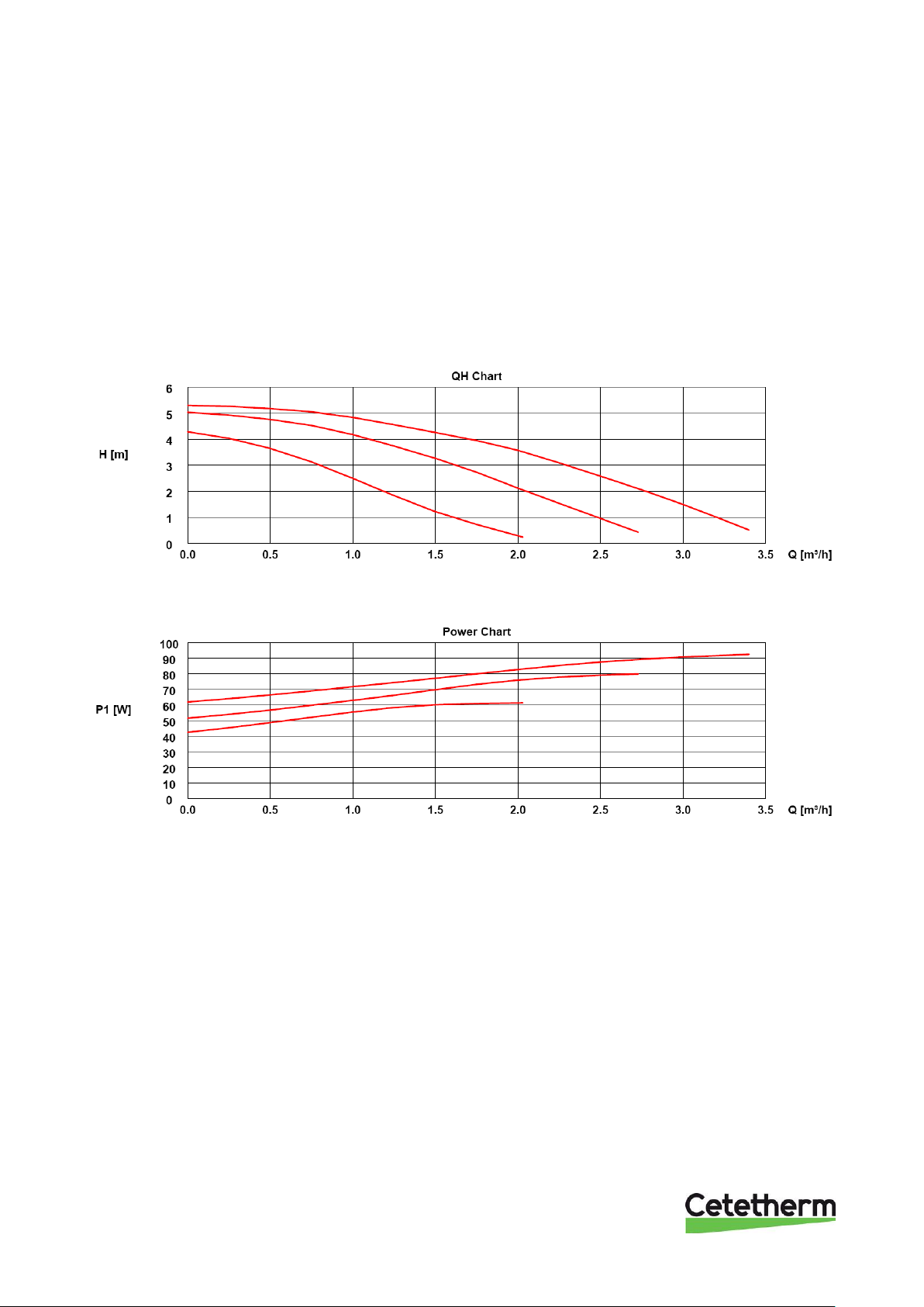
8.2 DHWC pump Grundfos UPSO 15-55, capacity
Picture 9
Picture 10
Page 21
Cetetherm Midi Wall IQHeat
Installation, service and operating instruction
19
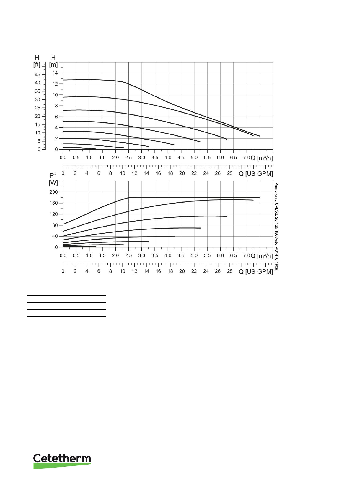
8.3 Heating circuit pump Grundfos UPMXL 25-125 180 Auto (GFJOC), settings and capacity
Picture 11
Settings
MAX.H
nom
CP1
7,5 m
CP2
10 m
CP3
12,5 m
PP1
8 m
PP2
9,5 m
PP3
11 m
Page 22
Cetetherm Midi Wall IQHeat
Installation, service and operating instruction
20
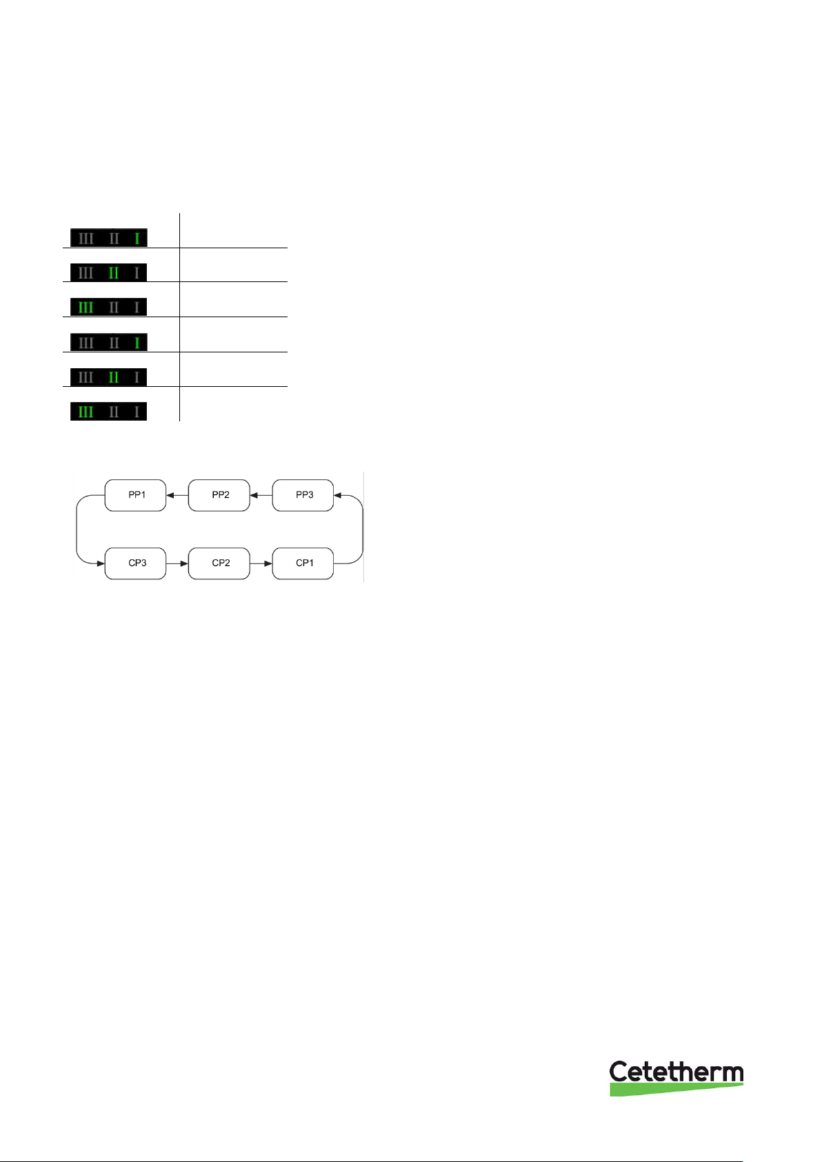
The heating pump is internally controlled via digital pulse-width modulation.
The user interface allows to select between six control curves in two control modes:
• three proportional pressure curves (PP)
• three constant pressure/power curves (CP).
The pump is factory preset to Proportional pressure curve, PP2.
Flashing fast
PP1
Flashing fast
PP2
Flashing fast
PP3
Flashing slow
CP1
Flashing slow
CP2
Flashing slow
CP3
Picture 12, LED indication of the curve setting
8.3.1 Changing pump curve setting
Picture 13, Serial curve setting
1. Push the button for two seconds
Pump goes to setting mode - LED starts flashing.
2. With each push, the setting changes:
LED 1-2-3 are permanently on, and then the control curve and mode is changed.
3. Flashing mode:
• Fast: Proportional pressure
• Slow: Constant pressure/power
4. After ten seconds not pushing the button:
• Setting is adapted.
• Pump returns to operating mode
5. LED 1 or 2 or 3 is permanently on.
• Pump is running with the selected curve and mode.
Page 23
Cetetherm Midi Wall IQHeat
Installation, service and operating instruction
21
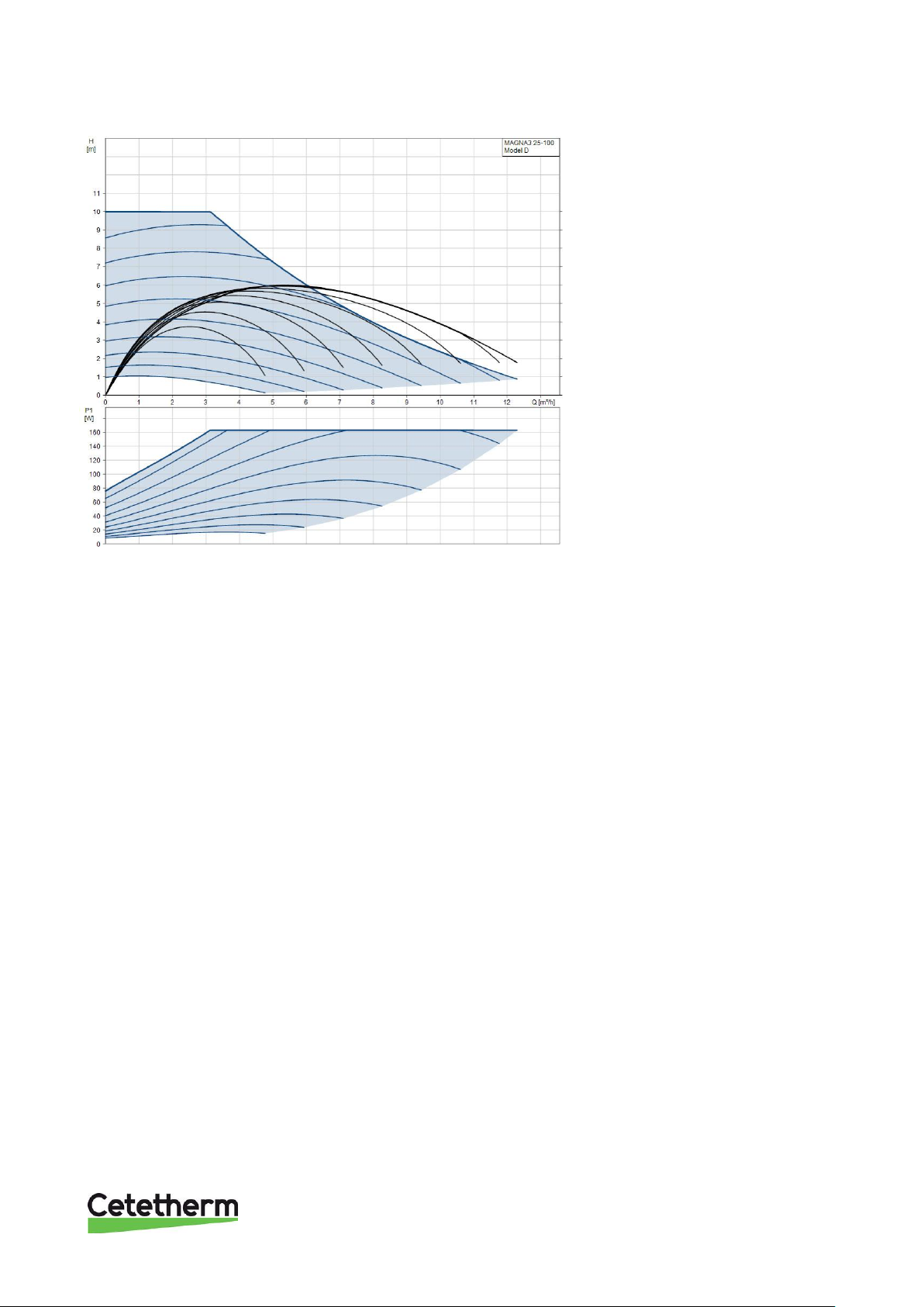
8.4 Heating circuit pump Grundfos Magna3 25-100, capacity
Picture 14
Page 24
Cetetherm Midi Wall IQHeat
Installation, service and operating instruction
22
9 Service instructions
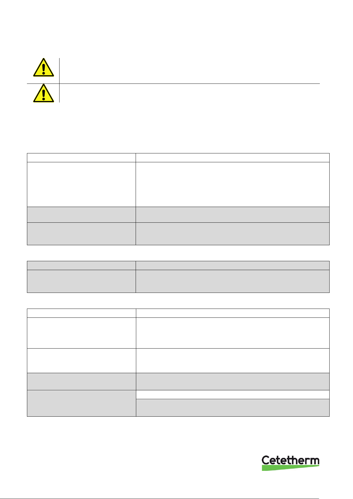
To avoid the risk of scalding, make sure that no-one draws any water while servicing the
substation.
Grey marked service actions must be carried out by an authorized service technician.
NOTE: Make sure that the Midi Wall substation has been correctly installed.
For more information about IQHeat, see User instruction IQHeat Doc-1552.
9.1 Tap water, service instructions
9.1.1 Tap water too cold
Reason
Action
District heating supply too low
Check the primary inlet temperature
The temperature can be checked by means of the energy meter,
minimum 65ºC, or at the district heating medium supply.
The hot water drain temperature can be monitored on the control panel
display, see User instruction IQHeat Doc-1552 chapter Hot water
circuit.
District heating strainer clogged
See
10.1 Check if the district heating strainer is blocked.
Hot water valve and actuator does not
work
See
10.2 Check the function of the heating and hot water valve and
actuator.
9.1.2 Tap water too warm
Reason
Action
Hot water valve and actuator does not
work
See
10.2 Check the function of the heating and hot water valve and
actuator.
9.1.3 Hot water temperature unstable
Reason
Action
Pending differential pressure
Check available differential pressure and the primary inlet
temperature
The temperature can be checked by means of the energy meter,
minimum 65ºC, or at the district heating medium supply.
Faulting settings for drain hot water
Check pre-set parameters on control panel display
Check set value for drain hot water, see User instruction IQHeat Doc-
1552 chapter Hot water circuit.
District heating strainer clogged
See
10.1 Check if the district heating strainer is blocked.
DHWC pump is not running
Check that the electrical power is on.
See
10.4 Check DHWC pump.
Page 25
Cetetherm Midi Wall IQHeat
Installation, service and operating instruction
23
9.1.4 Nosie in the DHWC system
Reason
Action
The DHWC pump capacity set too
high
Reduce the pump capacity
Reduce the pump capacity by selecting a lower setting on the pump
when needed.
Air in the DHWC pump
Vent the DHWC pump
Set the pump to speed III. Loosen the pump motor end nut to and let it
stay opened until the air in the pump is released. When the pump has
been vented, i.e. when the noise has ceased, set the pump according
to the recommendations.
The DHWC pump motor or pump
component damaged
Change pump components or the complete DHWC pump
If it becomes necessary to change the driving side of the pump, it can
be dismantled without removing the whole pump.
See chapter 11 Maintenance and repairs.
9.2 Heating system, service instruction
9.2.1 Heating system temperature too high or too low
Reason
Action
Heating supply temperature sensor
and outdoor temperature sensor does
not work
Check the heating supply temperature sensor and outdoor
temperature sensor for correct placement and function.
The two temperatures can be monitored on the control panel display,
see document User instruction IQHeat Doc-1552 chapter General
Functions section Reading the current temperatures and valve modes.
The heating control equipment may
need to be adjusted
Check and adjust the heating curve
See chapter Heating circuit in User instruction IQHeat Doc-1552.
Heating circuit strainer clogged
See 10.3 Check heating circuit strainer.
Heating valve and/or actuator does not
work
See
10.2 Check the function of the heating and hot water valve and
actuator.
9.2.2 No heating
Reason
Action
Circulation pump not running
Check that the electrical power is on.
Air pockets in the substation or in the
heating circuit
Check the circulation pump
If the pump fails to start after stopping, start the pump at the highest
setting.
Check pre-set heating parameters on the control panel display
• set operating mode
• set time and date
• night time decrease
• week program
• weekend decrease
See User instruction IQHeat Doc-1552.
To check operating mode, time and date see section Reading the
current temperatures and valve modes in chapter General Functions.
For more information about heating settings see chapter Heating
Circuit.
Page 26
Cetetherm Midi Wall IQHeat
Installation, service and operating instruction
24
Vent the pump
The pump is self-venting.
Possible remaining air in the pump may cause noise. This noise
ceases after a few minutes run time.
Heating supply temperature sensor
and outdoor temperature sensor does
not work
Check the heating supply temperature sensor and outdoor
temperature sensor for correct placement and function.
The two temperatures can be monitored on the control panel display,
see document User instruction IQHeat Doc-1552 chapter General
Functions section Reading the current temperatures and valve modes.
Loss of function in the heating control
unit.
See 10.5 Run the pump manually.
Heating circuit strainer clogged
See 10.3 Check heating circuit strainer.
9.2.3 Noise in the radiator system
Reason
Action
The heating pump capacity set too
high
Reduce the pump capacity
Reduce the pump capacity by selecting a lower setting on the pump
when needed.
Air in the heating pump
Vent the pump
The pump is self-venting.
Possible remaining air in the pump may cause noise. This noise
ceases after a few minutes run time.
The heating pump motor or pump
component damaged
Change pump components or the complete pump
If it is necessary to change the driving side of the pump, it can be
dismantled without removing the entire pump.
See chapter 11 Maintenance and repairs.
9.2.4 Heating temperature unstable
Reason
Action
Pending differential pressure
Check available differential pressure and the primary inlet
temperature
The temperature can be checked by means of the energy meter,
minimum 65ºC, or at the district heating medium supply.
Heating supply temperature sensor
and outdoor temperature sensor does
not work
Check the heating supply temperature sensor and outdoor
temperature sensor for correct placement and function.
The two temperatures can be monitored on the control panel display,
see document User instruction IQHeat Doc-1552 chapter General
Functions section Reading the current temperatures and valve modes.
District heating strainer clogged
See 10.1 Check if the district heating strainer is blocked.
9.2.5 Heating system often needs topping up
Reason
Action
Leaks in the substation or in the
system
Check the substation and the system for leaks
Leaks from the substation or the heating system cause pressure drops.
Repair any leaks on the substation.
The heating system safety valve is
leaking or does not work
Check the heating system safety valve
Check that the safety valve is not leaking and that it works properly.
Check the safety valves’ function by turning the wheel/knob until water
runs out of the valve’s waste pipe and then close the valve quickly.
The expansion vessel cannot handle
the systems volume changes
See 10.6 Check the volume take-up and pressure equalizing of the
expansion vessel.
Page 27
Cetetherm Midi Wall IQHeat
Installation, service and operating instruction
25
10 Service actions for the installer
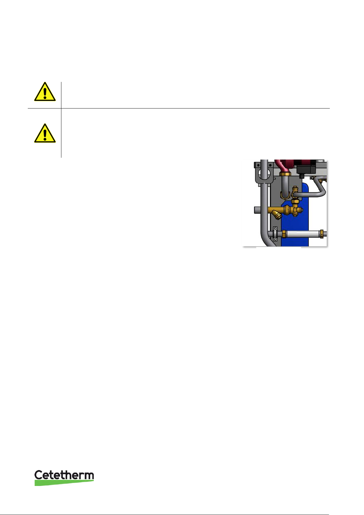
10.1 Check if the district heating strainer is blocked
Service actions must be carried out by an authorized service technician.
Before starting out repairs always close the primary supply and return shutoff valves and drain
the system.
After finishing repair; open the shutoff valves. Start with primary supply and then the return lines,
to avoid pollutions in the system. Open the valves slowly to avoid pressure surges.
Do the same on the heating side open first heat return and then supply. Fill up the system, start
the pump and vent.
Release the strainer holder and remove the cartridge.
Clean the strainer with water and refit the cartridge.
Screw the strainer holder with a momentum of 10-20 Nm.
Picture 15
Page 28
Cetetherm Midi Wall IQHeat
Installation, service and operating instruction
26
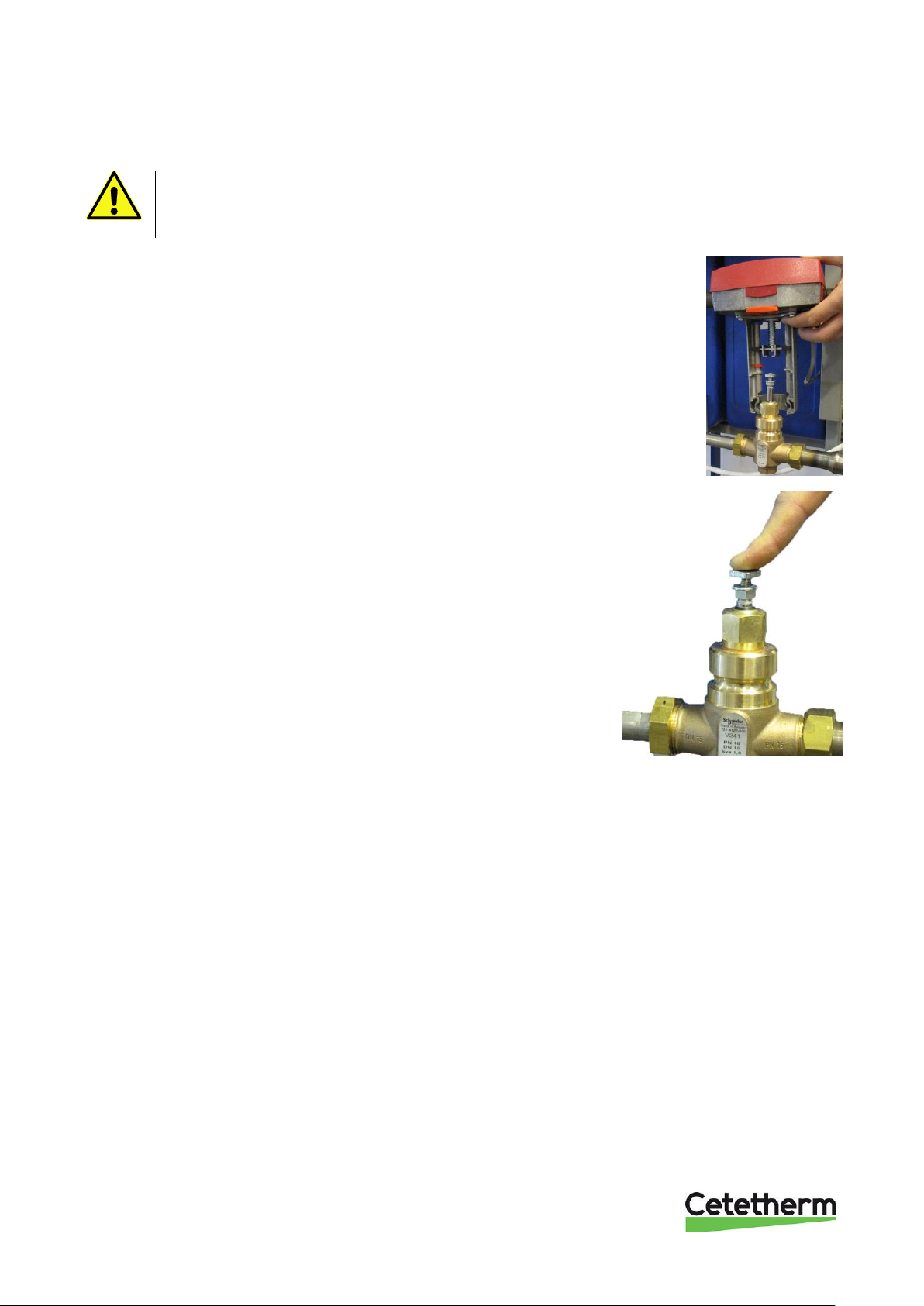
10.2 Check the function of the heating and hot water valve and actuator
See User instruction IQHeat Doc-1552 chapter Tests section Testing the valves.
Service actions must be carried out by an authorized service technician.
Before the hot water valve can be checked the actuator must be dismantled.
Unscrew the screws on the shackle holding the actuator to the valve and
dismantle the actuator from the valve
Picture 16
Press the valve guide pin gently and check the valve´s travel and spring
back.
Note: The valve may be very hot!
Picture 17
Page 29
Cetetherm Midi Wall IQHeat
Installation, service and operating instruction
27
Picture 18
10.3 Check heating circuit strainer
Service actions must be carried out by an authorized service technician.
Before starting out repairs always close the primary supply and return shutoff valves and drain the
system.
After finishing repair; open the shutoff valves. Start with primary supply and then the return lines,
to avoid pollutions in the system. Open the valves slowly to avoid pressure surges.
Do the same on the heating side open first heat return and then supply. Fill up the system, start
the pump and vent.
Disconnect the electrical power supply.
Release the strainer holder and remove the cartridge.
Clean the strainer in water and refit the cartridge. Screw the strainer
holder with a momentum of 10-20 Nm.
10.4 Check DHWC pump
Service actions must be carried out by an authorized service technician.
Disconnect the power feed to the pump by pulling off the connecter before carrying out this task.
If the current is on when you use a screwdriver to assist the pump to start, the screwdriver may
be wrenched out of your hand when the pump starts.
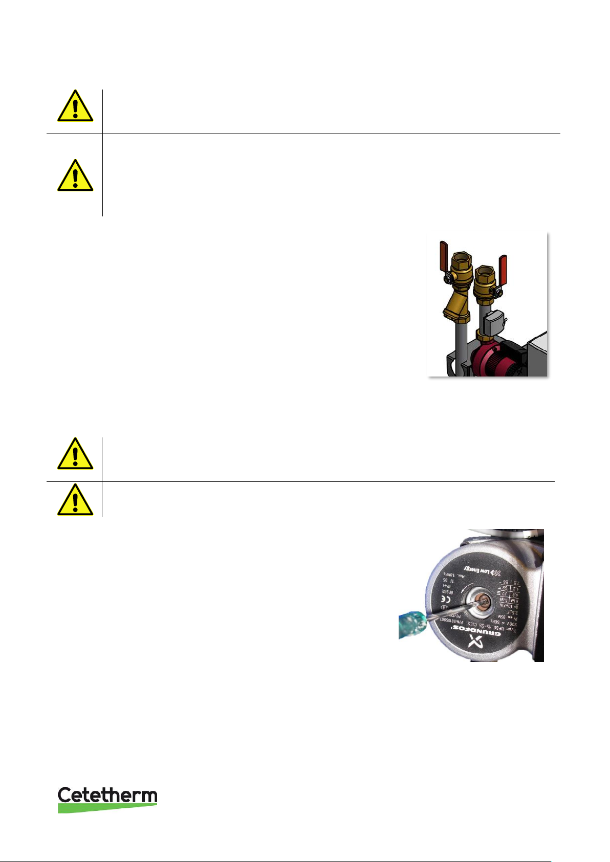
If the pump does not start, can it normally be started by removing the
pump motor end nut and helping the pump to start with the aid of a
screwdriver in the notch on the engine shaft.
If possible, use a short screwdriver. If the pump is difficult to access,
disconnect the heating actuator.
Connect the power feed to the pump and try to start again.
Picture 19
Page 30
Cetetherm Midi Wall IQHeat
Installation, service and operating instruction
28
10.5 Run the pump manually
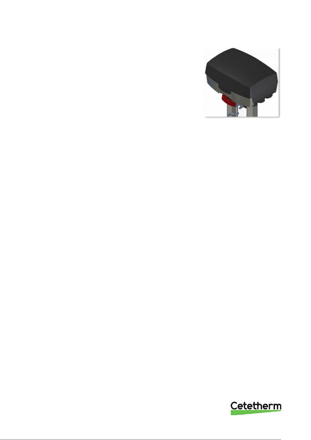
If it becomes necessary to run the pump and actuator manually, this can
be done by disconnecting the power to the operator control panel.
Disconnect the electrical plug for the pump and connect the
replacement cable to the power supply and to the circulation pump.
Next, open the heating valve manually using the red knob on the
actuator.
Flick down the red knob and open the valve enough to supply the house
property´s heating demand. This is to be regarded as a temporary
solution until the control unit problem is solved.
Picture 20
10.6 Check the volume take-up and pressure equalizing of the expansion vessel
Check the expansion vessel for possible leakage.
The cause may be that the expansion vessel cannot manage the volume changes on the heating side.
See 11.6 Change the expansion vessel.
Alternatively, the system´s total volume of water may be too high, i.e. the volume changes are too large for the
expansion vessel. If so, add extra expansion volume.
Page 31
Cetetherm Midi Wall IQHeat
Installation, service and operating instruction
29
11 Maintenance and repairs
Maintenance work must be carried out by an authorized service technician.
11.1 Change the pumps
Either change the complete pump or just the pump motor.
Maintenance work must be carried out by an authorized service technician.
Disconnecting the power feed to the pump and the substation.
Before starting out repairs always close the primary supply and return shutoff valves and drain
the system.
After finishing repair; open the shutoff valves. Start with primary supply and then the return lines,
to avoid pollutions in the system. Open the valves slowly to avoid pressure surges.
Do the same on the heating side open first heat return and then supply. Fill up the system, start
the pump and vent.
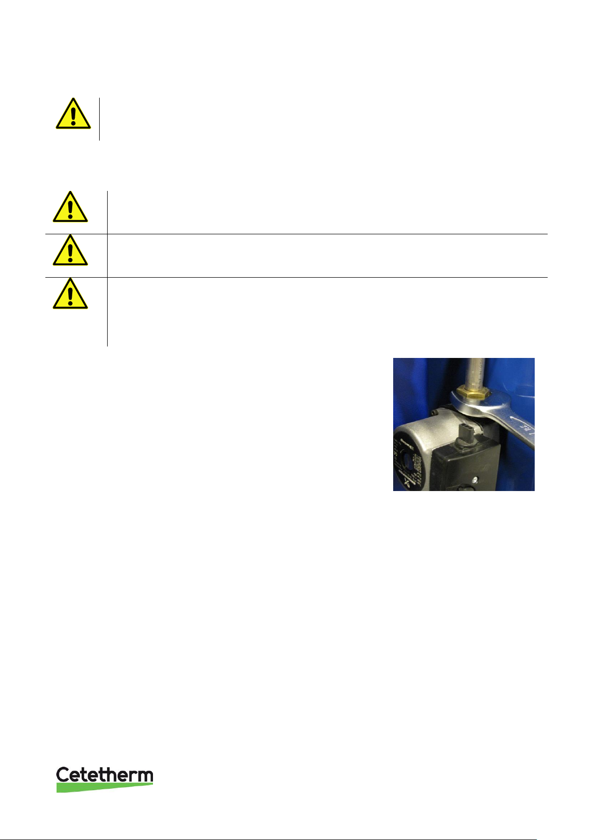
1. Release the brass nuts with a wrench and replace the pump.
2. Reattach the power feed.
3. If only changing the motor, release it by unscrewing four socket
head cap screws and replace the motor.
4. Reattach the power feed.
Picture 21
Page 32
Cetetherm Midi Wall IQHeat
Installation, service and operating instruction
30
11.2 Change the heating and hot water actuator
Maintenance work must be carried out by an authorized service technician.
Disconnecting the power feed to the pump and the substation.
1. Open actuator lid and unscrew connecting wires attached
to the wire terminal (Picture 38).
2. Unscrew the brace attaching the actuator to the valve and
lift of the actuator.
3. Mount a new actuator on the valve, slide the actuator onto
the valve neck, thus making the square nut on the valve
spindle fit into the groove on the cross bar. Then slide the
brace into the groove on the valve neck and secure the
nuts.
4. Reattach the wire terminal per the 6.4 Electrical circuit
diagram.
Picture 22
11.3 Change the heating or hot water valve
Maintenance work must be carried out by an authorized service technician.
Disconnecting the power feed to the pump and the substation.
Before starting out repairs always close the primary supply and return shutoff valves and
drain the system.
After finishing repair; open the shutoff valves. Start with primary supply and then the
return lines, to avoid pollutions in the system. Open the valves slowly to avoid pressure
surges.
Do the same on the heating side open first heat return and then supply. Fill up the
system, start the pump and vent.
1. Unscrew the heating actuator from the control valve.
2. Use a wrench to remove the control valve. Note the arrow
direction on the valve.
3. Mount a new valve; and take especially care to the arrow
direction.
4. Mount the actuator on the valve, slide the actuator onto the
valve neck, thus making the square nut on the valve spindle
fit into the groove on the cross bar. Then slide the brace into
the groove on the valve neck and secure the nuts.
Picture 23
Page 33
Cetetherm Midi Wall IQHeat
Installation, service and operating instruction
31
11.4 Change the temperature sensor heating supply/return
1. Carefully lift the sensor cover with a screwdriver
and unscrew the connecting wires in attached to the wire
terminal.
Picture 24
2. Loose the band the holds the sensor to the pipe.
Replace with a new sensor.
Picture 25
11.5 Change the outdoor temperature sensor
1. Disconnect the electrical power supply.
2. Unscrew the lid by turning it anti-clockwise.
3. Unscrew the cables.
4. Loosen the cable fitting.
5. Install a new outdoor temperature sensor.
Picture 26
11.6 Change the expansion vessel
Maintenance work must be carried out by an authorized service technician.
Disconnecting the power feed to the pump and the substation.
Close the shutoff valves for the radiator supply and return.
Replace the expansion vessel.
Page 34
Cetetherm Midi Wall IQHeat
Installation, service and operating instruction
32
12 Options
The mounting instructions are described for a new installation. If the kits are supposed to be installed on an
already installed subsystem, you will have to release the water pressure and disconnect the electrical power
supply before starting. The installation must be carried out by a fully qualified electrician.
12.1 3-point HB metering
Mounting the 3-point HB metering:
1. Close the shut-off valves for primary inlet and return.
2. Unscrew the nut preceding the energy meter and remove energy meter and pipe.
3. Unscrew the nut following primary inlet and remove the filter and welding end.
4. Thread the metering profile into the frame´s.
5. Screw the metering and the central together.
6. Open the shut-off valves, first primary inlet then primary return.
Picture 28
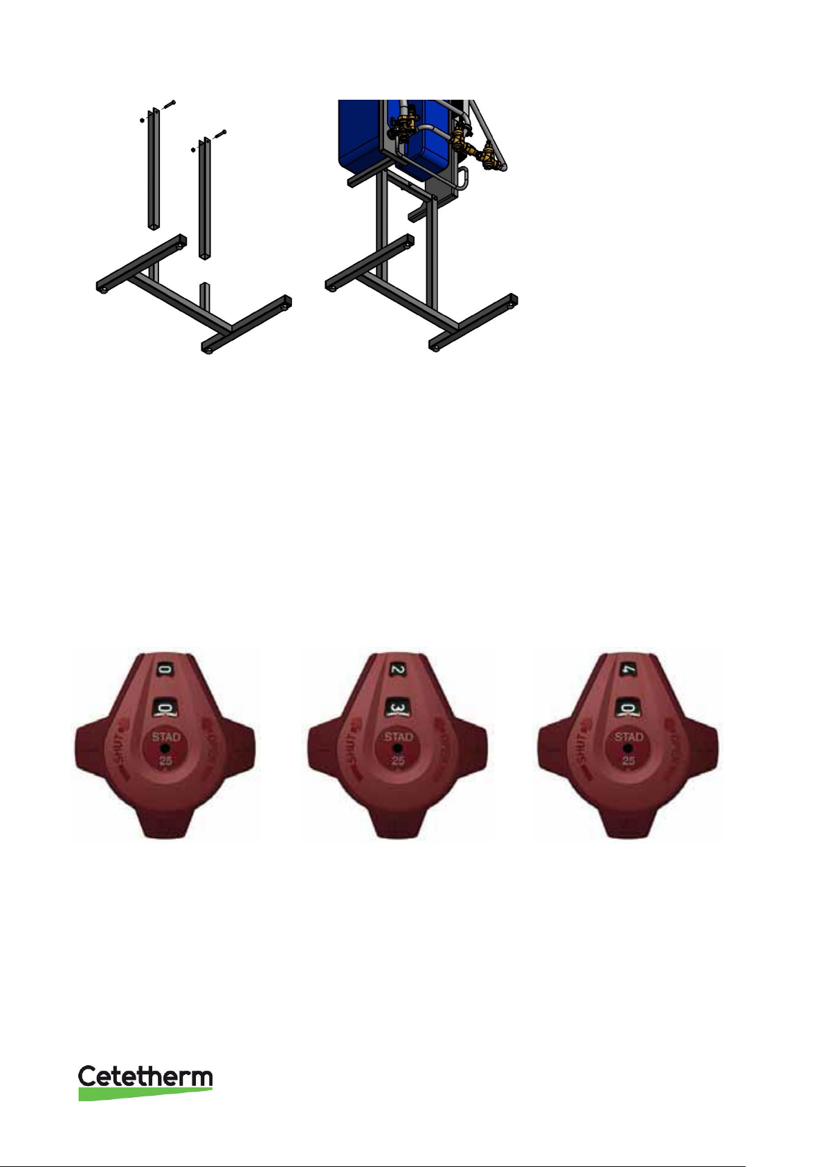
12.2 Mounting floor stand
1. Mount two floor supports to the central. Use the outer mounting holes.
2. Mount the floor stand feet on the floor support.
3. Raise the central against a wall.
4. We recommend that the central is mounted to the wall.
The distance between floor and screw bracket should be 1330 mm. Note that distance between screws
are 400 mm.
Picture 27
Page 35
Cetetherm Midi Wall IQHeat
Installation, service and operating instruction
33
Picture 29
Picture 30
12.3 Balancing valve DHWC
Set the valve to a specific pressure drop according to:
1. Close the valve fully.
2. Open the valve the correct numbers of turns.
3. See the diagram for numbers of turns. In this example 2,3 turns.
4. Using a 3 mm Allen key, turn the inner spindle clockwise until stop.
5. The valve is now set.
To check the setting: Close the valve, the indicator shows 0.0. Open it to the stop position. The indicator then
shows the set value, in this case 2.3.
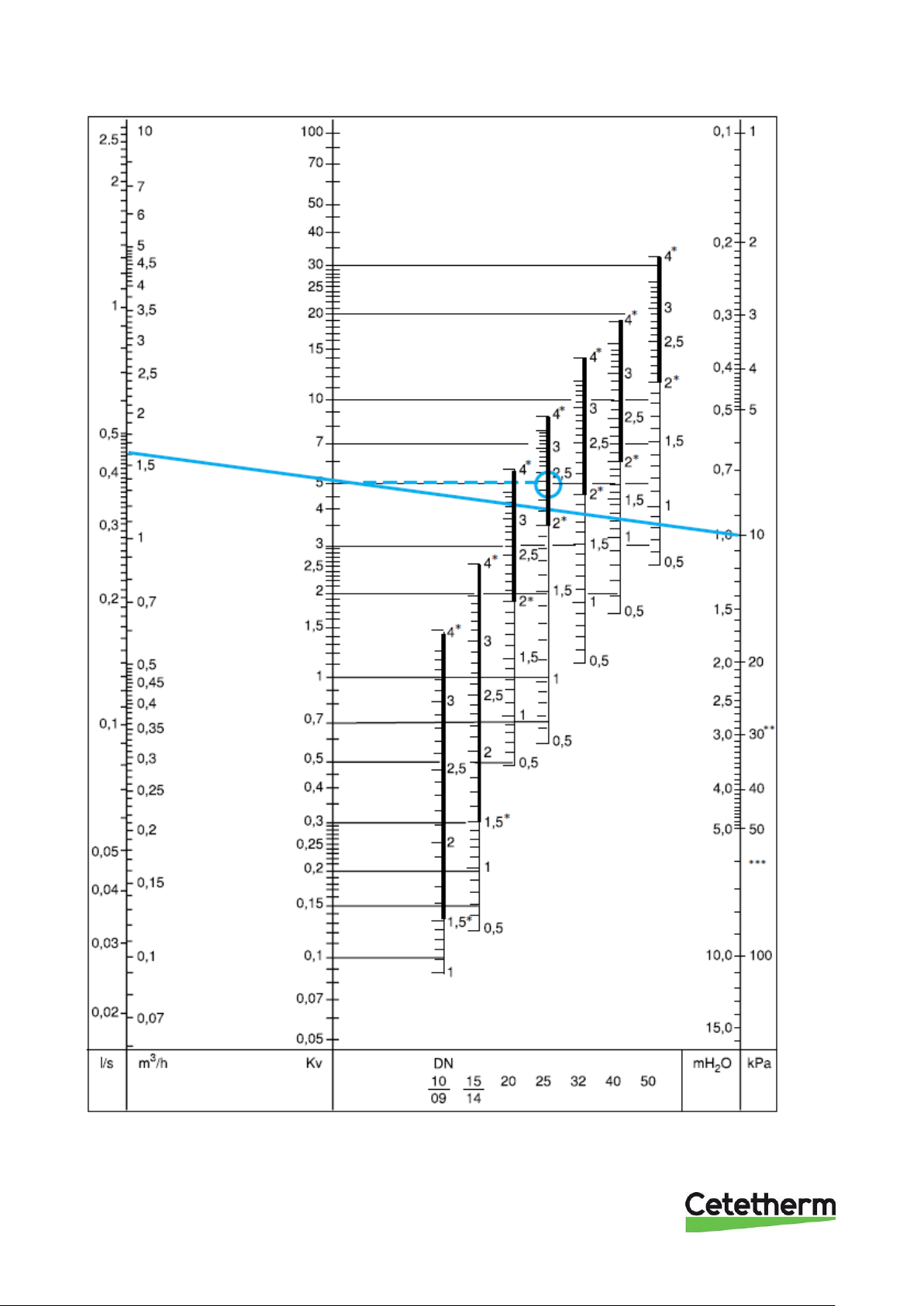
The diagram shows the pressure drop for different settings and flow rates.
Four turns correspond to fully opened valve. Opening it further will not increase the capacity.
Picture 31
Picture 32
Picture 33
Page 36
Cetetherm Midi Wall IQHeat
Installation, service and operating instruction
34
Picture 34
*) recommended area
**) 25 dB (A)
***) 35 dB (A)
Page 37
Cetetherm Midi Wall IQHeat
Installation, service and operating instruction
35
13 Technical data and performance
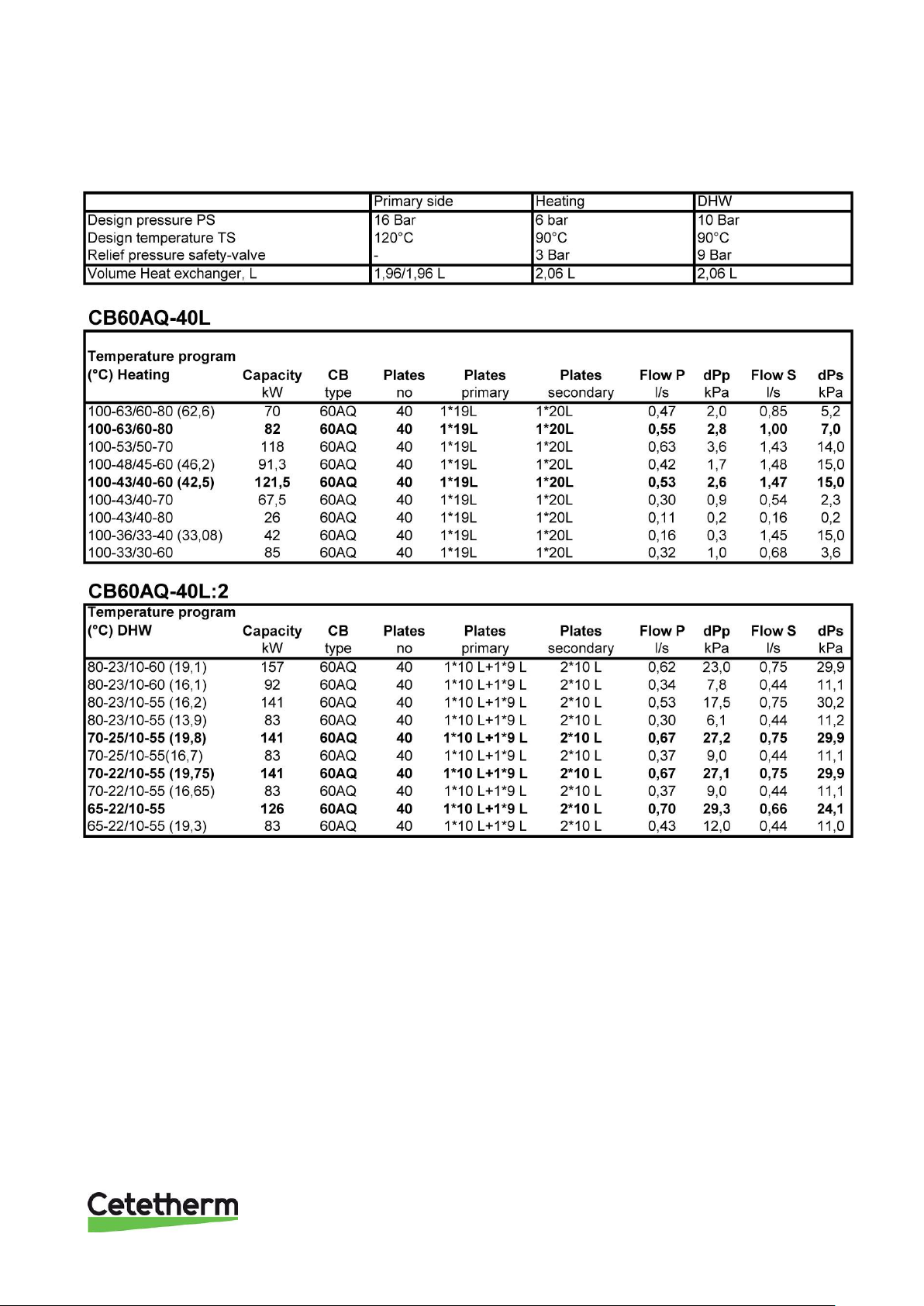
13.1 Operation data Midi Wall 70
Page 38
Cetetherm Midi Wall IQHeat
Installation, service and operating instruction
36
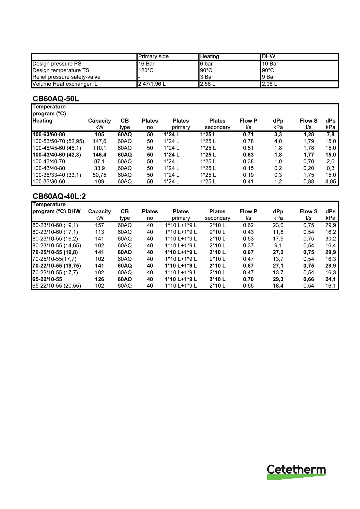
13.2 Operation data Midi Wall 100
Page 39
Cetetherm Midi Wall IQHeat
Installation, service and operating instruction
37
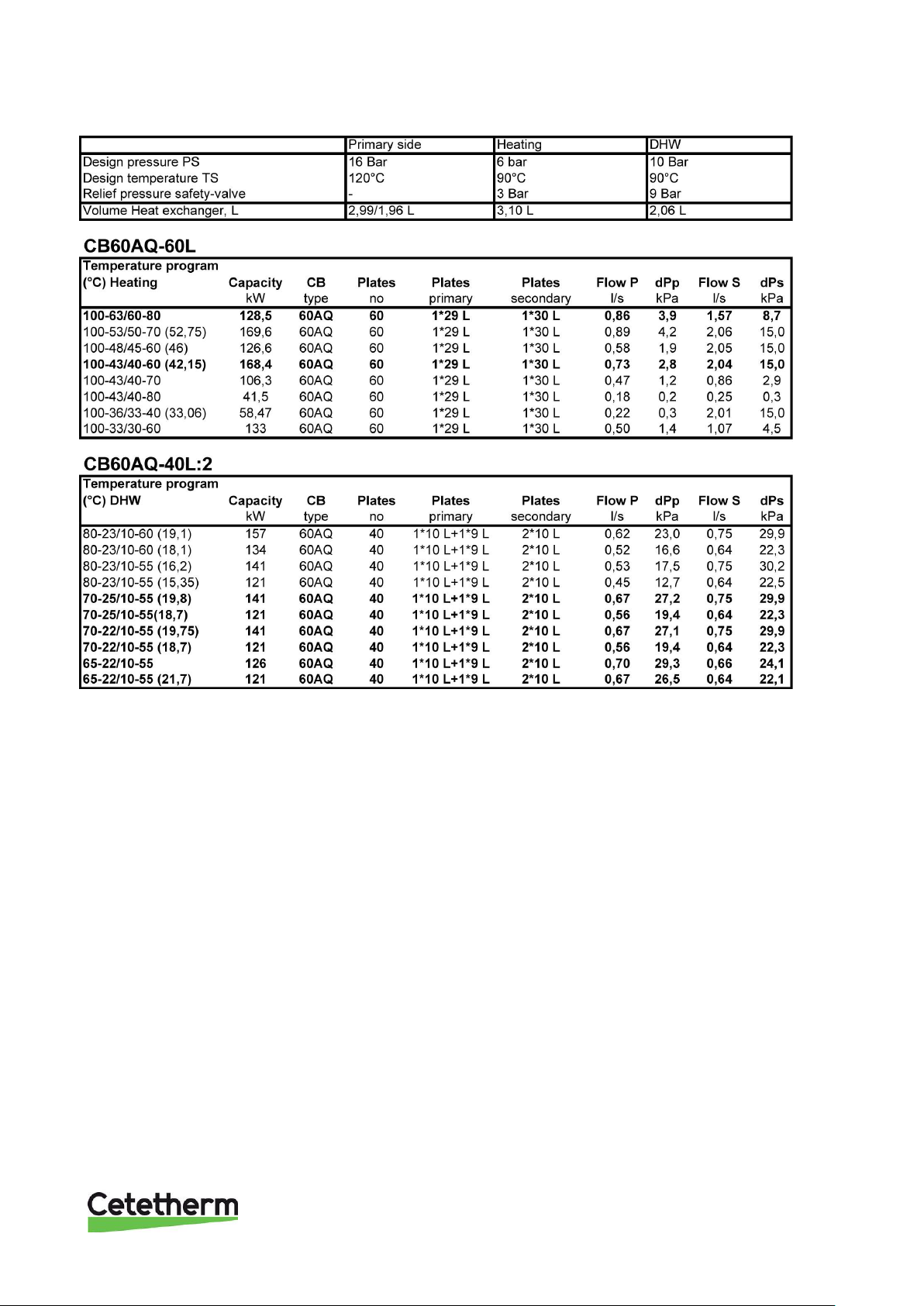
13.3 Operation data Midi Wall 130
13.4 Technical data
Electrical data:
230V 50Hz 1-phase 290-315W
Noise level:
<70dB(A), 1,6 m above floor level, 1 m from source
Main measurements:
730x510x1115 mm (WxDxH)
Weight:
65-85 kg
Page 40

 Loading...